EP4020774B1 - Motor rotor, motor, and vehicle - Google Patents
Motor rotor, motor, and vehicle Download PDFInfo
- Publication number
- EP4020774B1 EP4020774B1 EP21214330.9A EP21214330A EP4020774B1 EP 4020774 B1 EP4020774 B1 EP 4020774B1 EP 21214330 A EP21214330 A EP 21214330A EP 4020774 B1 EP4020774 B1 EP 4020774B1
- Authority
- EP
- European Patent Office
- Prior art keywords
- conductive
- bearing
- motor
- wall
- conductive pillar
- Prior art date
- Legal status (The legal status is an assumption and is not a legal conclusion. Google has not performed a legal analysis and makes no representation as to the accuracy of the status listed.)
- Active
Links
Images





Classifications
-
- H—ELECTRICITY
- H02—GENERATION; CONVERSION OR DISTRIBUTION OF ELECTRIC POWER
- H02K—DYNAMO-ELECTRIC MACHINES
- H02K1/00—Details of the magnetic circuit
- H02K1/06—Details of the magnetic circuit characterised by the shape, form or construction
- H02K1/22—Rotating parts of the magnetic circuit
- H02K1/28—Means for mounting or fastening rotating magnetic parts on to, or to, the rotor structures
-
- H—ELECTRICITY
- H02—GENERATION; CONVERSION OR DISTRIBUTION OF ELECTRIC POWER
- H02K—DYNAMO-ELECTRIC MACHINES
- H02K11/00—Structural association of dynamo-electric machines with electric components or with devices for shielding, monitoring or protection
- H02K11/40—Structural association with grounding devices
-
- F—MECHANICAL ENGINEERING; LIGHTING; HEATING; WEAPONS; BLASTING
- F16—ENGINEERING ELEMENTS AND UNITS; GENERAL MEASURES FOR PRODUCING AND MAINTAINING EFFECTIVE FUNCTIONING OF MACHINES OR INSTALLATIONS; THERMAL INSULATION IN GENERAL
- F16C—SHAFTS; FLEXIBLE SHAFTS; ELEMENTS OR CRANKSHAFT MECHANISMS; ROTARY BODIES OTHER THAN GEARING ELEMENTS; BEARINGS
- F16C19/00—Bearings with rolling contact, for exclusively rotary movement
- F16C19/52—Bearings with rolling contact, for exclusively rotary movement with devices affected by abnormal or undesired conditions
-
- H—ELECTRICITY
- H02—GENERATION; CONVERSION OR DISTRIBUTION OF ELECTRIC POWER
- H02K—DYNAMO-ELECTRIC MACHINES
- H02K5/00—Casings; Enclosures; Supports
- H02K5/04—Casings or enclosures characterised by the shape, form or construction thereof
- H02K5/15—Mounting arrangements for bearing-shields or end plates
-
- H—ELECTRICITY
- H02—GENERATION; CONVERSION OR DISTRIBUTION OF ELECTRIC POWER
- H02K—DYNAMO-ELECTRIC MACHINES
- H02K5/00—Casings; Enclosures; Supports
- H02K5/04—Casings or enclosures characterised by the shape, form or construction thereof
- H02K5/16—Means for supporting bearings, e.g. insulating supports or means for fitting bearings in the bearing-shields
- H02K5/165—Means for supporting bearings, e.g. insulating supports or means for fitting bearings in the bearing-shields radially supporting the rotor around a fixed spindle; radially supporting the rotor directly
-
- H—ELECTRICITY
- H02—GENERATION; CONVERSION OR DISTRIBUTION OF ELECTRIC POWER
- H02K—DYNAMO-ELECTRIC MACHINES
- H02K5/00—Casings; Enclosures; Supports
- H02K5/04—Casings or enclosures characterised by the shape, form or construction thereof
- H02K5/16—Means for supporting bearings, e.g. insulating supports or means for fitting bearings in the bearing-shields
- H02K5/173—Means for supporting bearings, e.g. insulating supports or means for fitting bearings in the bearing-shields using bearings with rolling contact, e.g. ball bearings
- H02K5/1732—Means for supporting bearings, e.g. insulating supports or means for fitting bearings in the bearing-shields using bearings with rolling contact, e.g. ball bearings radially supporting the rotary shaft at both ends of the rotor
-
- H—ELECTRICITY
- H02—GENERATION; CONVERSION OR DISTRIBUTION OF ELECTRIC POWER
- H02K—DYNAMO-ELECTRIC MACHINES
- H02K7/00—Arrangements for handling mechanical energy structurally associated with dynamo-electric machines, e.g. structural association with mechanical driving motors or auxiliary dynamo-electric machines
- H02K7/003—Couplings; Details of shafts
-
- F—MECHANICAL ENGINEERING; LIGHTING; HEATING; WEAPONS; BLASTING
- F16—ENGINEERING ELEMENTS AND UNITS; GENERAL MEASURES FOR PRODUCING AND MAINTAINING EFFECTIVE FUNCTIONING OF MACHINES OR INSTALLATIONS; THERMAL INSULATION IN GENERAL
- F16C—SHAFTS; FLEXIBLE SHAFTS; ELEMENTS OR CRANKSHAFT MECHANISMS; ROTARY BODIES OTHER THAN GEARING ELEMENTS; BEARINGS
- F16C19/00—Bearings with rolling contact, for exclusively rotary movement
- F16C19/02—Bearings with rolling contact, for exclusively rotary movement with bearing balls essentially of the same size in one or more circular rows
- F16C19/04—Bearings with rolling contact, for exclusively rotary movement with bearing balls essentially of the same size in one or more circular rows for radial load mainly
- F16C19/06—Bearings with rolling contact, for exclusively rotary movement with bearing balls essentially of the same size in one or more circular rows for radial load mainly with a single row or balls
-
- F—MECHANICAL ENGINEERING; LIGHTING; HEATING; WEAPONS; BLASTING
- F16—ENGINEERING ELEMENTS AND UNITS; GENERAL MEASURES FOR PRODUCING AND MAINTAINING EFFECTIVE FUNCTIONING OF MACHINES OR INSTALLATIONS; THERMAL INSULATION IN GENERAL
- F16C—SHAFTS; FLEXIBLE SHAFTS; ELEMENTS OR CRANKSHAFT MECHANISMS; ROTARY BODIES OTHER THAN GEARING ELEMENTS; BEARINGS
- F16C2326/00—Articles relating to transporting
- F16C2326/01—Parts of vehicles in general
-
- F—MECHANICAL ENGINEERING; LIGHTING; HEATING; WEAPONS; BLASTING
- F16—ENGINEERING ELEMENTS AND UNITS; GENERAL MEASURES FOR PRODUCING AND MAINTAINING EFFECTIVE FUNCTIONING OF MACHINES OR INSTALLATIONS; THERMAL INSULATION IN GENERAL
- F16C—SHAFTS; FLEXIBLE SHAFTS; ELEMENTS OR CRANKSHAFT MECHANISMS; ROTARY BODIES OTHER THAN GEARING ELEMENTS; BEARINGS
- F16C2380/00—Electrical apparatus
- F16C2380/26—Dynamo-electric machines or combinations therewith, e.g. electro-motors and generators
-
- H—ELECTRICITY
- H02—GENERATION; CONVERSION OR DISTRIBUTION OF ELECTRIC POWER
- H02K—DYNAMO-ELECTRIC MACHINES
- H02K1/00—Details of the magnetic circuit
- H02K1/06—Details of the magnetic circuit characterised by the shape, form or construction
- H02K1/22—Rotating parts of the magnetic circuit
- H02K1/32—Rotating parts of the magnetic circuit with channels or ducts for flow of cooling medium
-
- H—ELECTRICITY
- H02—GENERATION; CONVERSION OR DISTRIBUTION OF ELECTRIC POWER
- H02K—DYNAMO-ELECTRIC MACHINES
- H02K2213/00—Specific aspects, not otherwise provided for and not covered by codes H02K2201/00 - H02K2211/00
- H02K2213/03—Machines characterised by numerical values, ranges, mathematical expressions or similar information
-
- H—ELECTRICITY
- H02—GENERATION; CONVERSION OR DISTRIBUTION OF ELECTRIC POWER
- H02K—DYNAMO-ELECTRIC MACHINES
- H02K5/00—Casings; Enclosures; Supports
- H02K5/04—Casings or enclosures characterised by the shape, form or construction thereof
- H02K5/16—Means for supporting bearings, e.g. insulating supports or means for fitting bearings in the bearing-shields
- H02K5/173—Means for supporting bearings, e.g. insulating supports or means for fitting bearings in the bearing-shields using bearings with rolling contact, e.g. ball bearings
-
- H—ELECTRICITY
- H02—GENERATION; CONVERSION OR DISTRIBUTION OF ELECTRIC POWER
- H02K—DYNAMO-ELECTRIC MACHINES
- H02K7/00—Arrangements for handling mechanical energy structurally associated with dynamo-electric machines, e.g. structural association with mechanical driving motors or auxiliary dynamo-electric machines
- H02K7/08—Structural association with bearings
Definitions
- Embodiments of this application relate to the field of drive motor technologies, and in particular, to a motor rotor, a motor, and a vehicle.
- a main part of an electric vehicle is an electric drive system, and a power source of the electric drive system is a motor.
- the motor converts electric energy into mechanical energy, to drive wheels of the electric vehicle to rotate, so as to drive the electric vehicle to travel.
- a shaft current is generated on a motor rotor.
- the main bearing is electrically corroded. This affects a service life of the main bearing.
- a conductive bearing and a conductive spring are disposed on a conventional motor rotor.
- the conductive bearing is disposed in a shaft hole of the motor rotor, and an outer ring of the conductive bearing abuts on an inner wall of the shaft hole.
- a conductive spring is pressed against an inner ring of the conductive bearing, and the other end of the conductive spring is grounded. In this way, the shaft current on the motor rotor is transmitted and discharged by using the conductive bearing and the conductive spring, and a strength of currents discharged to the main bearing is reduced, so that the main bearing is prevented from being electrically corroded by the shaft current.
- US 5,914,547 A discloses an auxiliary bearing assembly used to ground the shaft of an electric motor to reduce unwanted currents in the motor bearings.
- US 2018/0083515 A1 discloses an electric motor which includes a case, a stator having stator windings, a rotor having a rotor shaft, and at least one main rotor bearing coupling the rotor shaft to the case.
- Common mode charge builds up on the rotor due to imbalances of the stator.
- the at least one main rotor bearing has a first electrical resistance between the rotor shaft and the case.
- the electric motor further includes a rotor discharge bearing coupling the rotor shaft to the case.
- the rotor discharge bearing has a second electrical resistance between the rotor shaft and the case that is less than the first electrical resistance, causing the common mode charge to discharge through the rotor discharge bearing.
- This invention provides a motor rotor, a motor, and a vehicle, as defined in the appended set of claims, to resolve a problem that a conductive bearing in a conventional motor rotor and a main bearing are both electrically corroded by a shaft current because the conductive bearing cannot be stably grounded, and another potential problem.
- the conductive pillar passes through the inner ring of the conductive bearing, the outer wall of the conductive pillar interference fits with the inner ring of the conductive bearing, and an end of the conductive pillar is grounded. In this way, it is ensured that a shaft current on the rotor body is transmitted and discharged by using the conductive bearing and the conductive pillar, to prevent a main bearing of the motor rotor from being electrically corroded by the shaft current.
- the conductive bearing is sleeved on the grounded conductive pillar, so that the inner ring of the conductive bearing can interference fit with the outer wall of the conductive pillar, to enable the inner ring of the conductive bearing to be closely attached to the outer wall of the conductive pillar, and avoid the following case:
- the conductive bearing In a high-speed rotation process of the rotor body, the conductive bearing is in unstable contact with the conductive pillar because the rotor body drives the conductive bearing to move axially and radially, and consequently the shaft current cannot be discharged.
- the outer ring of the conductive bearing interference fits with an inner ring of the shaft hole.
- the motor rotor in this invention can ensure that the rotor body, the conductive bearing, and the conductive pillar are always electrically connected in a running process of the motor rotor, to ensure that the shaft current on the rotor body is successfully discharged by using the conductive bearing and the conductive pillar.
- the outer wall of the conductive pillar circumferentially abuts on the inner ring of the conductive bearing evenly, so that force is evenly exerted on the conductive bearing, and no offset loading force occurs. Therefore, the conductive bearing is prevented from being damaged due to concentrated stress, and the conductive bearing is prevented from being abnormally worn due to the offset loading force, to prevent conductive grease from overflowing because sealing rings on the conductive bearing are worn, and prolong a service life of the conductive bearing.
- the motor housing may be used as reference ground whose potential is zero, or may be in contact with a chassis of a vehicle to be indirectly connected to ground.
- an end of the conductive pillar is electrically connected to the grounding bracket, and the grounding bracket is connected to the motor housing of the motor.
- the conductive pillar may be connected to the motor housing by using the grounding bracket. Therefore, it is ensured that the shaft current on the conductive pillar can be discharged to the motor housing by using the grounding bracket or discharged to the ground by using the motor housing, and a grounding process of the conductive pillar is simplified, to improve assembling efficiency of the motor rotor.
- the elastic conductive member is disposed between the conductive pillar and the grounding bracket.
- the elastic conductive member has a length used for cushioning
- the length of the elastic conductive member is adaptively adjusted with movement of the conductive pillar, and the elastic conductive member is not torn. Therefore, it is ensured that the electrical connection between the conductive pillar and the grounding bracket is stable.
- the positioning hole is disposed on the grounding bracket, and an end of the conductive pillar internally passes through the positioning hole of the grounding bracket, so that radial movement of the conductive pillar in the rotor body is limited, to improve radial stability of the conductive pillar.
- the outer wall of the conductive pillar clearance fits with the inner wall of the positioning hole. Therefore, in the high-speed rotation process, the rotor body can drive the conductive bearing and the conductive pillar to move freely. This effectively prevents a rigid connection between the conductive pillar and the grounding bracket from hampering movement of the inner ring of the conductive bearing, to ensure that a structure of the conductive bearing is not damaged.
- the limiting structure is set as a plane on a partial side wall of the conductive pillar that is located inside the positioning hole, and a plane on at least a partial inner wall of the positioning hole.
- connection part is disposed on the grounding bracket, and the grounding bracket and the motor housing are stably connected to each other by using the connection part. This improves strength of a connection between the grounding bracket and the motor housing.
- the positioning hole is disposed on the body part connected to an end of the connection part. Therefore, a limiting effect on the conductive pillar is implemented, and structural strength of the grounding bracket is ensured, so that a service life of the grounding bracket is prolonged.
- the motor housing has three mounting holes, and at least three connection parts are disposed on the body part of the grounding bracket. In this way, this improves strength of the connection between the grounding bracket and the motor housing, and fully uses a structure of the motor housing.
- the avoidance groove is disposed on the connection part. In this way, when the rotor body moves axially in a direction of the connection part in the high-speed running process, the rotor body may enter the avoidance groove without directly colliding with a surface of the connection part, to avoid damage to a structure of the grounding bracket. In addition, disposition of the avoidance groove also prevents the grounding bracket from being interfered by the rotor body in a mounting process.
- the bearing housing is disposed in the shaft hole, and the conductive bearing is mounted in the bearing housing.
- This facilitates assembling of the conductive bearing into the shaft hole of the rotor body, and also improves axial stability of the conductive bearing and the conductive pillar in the shaft hole.
- the outer wall of the bearing housing interference fits with the inner wall of the shaft hole, and the outer ring of the conductive bearing interference fits with the inner wall of the bearing housing, so that the bearing housing is in closer contact with each of the rotor body and the conductive bearing. Therefore, it is ensured that the shaft current on the rotor body can be successfully transmitted to the bearing housing and the conductive bearing, and assembling stability of the bearing housing in the shaft hole and assembling stability of the conductive bearing in the bearing housing are also improved.
- the cooling path is formed between the outer wall of the bearing housing and the inner wall of the shaft hole.
- the cooling medium that is introduced into the shaft hole may enter the cooling path, to cool the bearing housing, the conductive bearing, and the conductive pillar. Therefore, the following case is avoided:
- the conductive bearing is heated and expanded in the high-speed running process of the motor rotor, and consequently a steel ball in the conductive bearing cannot rotate normally and a conductivity of the conductive grease decreases. Therefore, it is ensured that the conductive bearing and the conductive grease are stable.
- an end of the bearing housing that faces the grounding bracket is opened, to facilitate assembling of the conductive bearing and the conductive pillar.
- the base of the bearing housing plays a role of positioning the conductive bearing axially. In other words, provided that the conductive bearing is assembled on the base, positioning of the conductive bearing in the bearing housing can be completed. This improves assembling efficiency of the conductive bearing.
- the boss which is formed on the inner wall of the shaft hole, and by means of the end of the bearing housing that is away from the grounding bracket abutting on the boss, axial movement of the bearing housing in the rotor body is further limited.
- the boss plays a role in quickly positioning assembling of the bearing housing in the shaft hole, namely, provided that the bearing housing is placed downwards to abut on the boss, positioning of the bearing housing in the shaft hole is completed.
- the motor rotor is disposed in the motor, to prevent the main bearing of the motor from being electrically corroded by a shaft current.
- the conductive bearing is prevented from being abnormally worn. Therefore, conductive grease is prevented from overflowing because sealing rings on the conductive bearing are worn, a service life of the conductive bearing is prolonged, it is ensured that the shaft current on the motor rotor is discharged by using the conductive bearing, and the main bearing is not electrically corroded, to ensure that the motor runs normally.
- the motor is mounted on the vehicle, so that it is ensured that the motor of the vehicle can work stably, to stably drive the wheels.
- FIG. 1 is a schematic diagram of a structure of a motor according to an embodiment of this application
- FIG. 2 is a partially enlarged view of I in FIG. 1 .
- the motor includes a motor rotor 100 and a stator, the stator is movably sleeved on an outer periphery of the motor rotor 100, and the motor rotor 100 is connected to loads such as wheels.
- the motor rotor 100 includes a motor shaft 190, an iron core and an excitation winding that are sleeved on the motor shaft, and the like.
- the motor shaft 190 of the motor rotor 100 is connected to loads such as wheels, to drive, when the motor shaft 190 rotates, the wheels to rotate.
- the stator During working, the stator generates a rotating magnetic field in an air gap between the stator and the motor rotor 100.
- a direct current is applied to the excitation winding of the motor rotor 100, a static magnetic field with constant polarity is generated.
- the motor rotor 100 Under an action of armature reaction, the motor rotor 100 generates a torque relative to the stator, so that the motor shaft 190 drives loads such as wheels to move.
- the stator of the motor includes at least a motor housing 200.
- the motor housing 200 of the motor is mainly used as the stator of the motor. The following specifically describes a structure of the motor by using the motor housing 200 as the stator.
- the motor housing 200 and the motor rotor 100 are movably connected to each other by using a main bearing 300.
- a main bearing 300 For example, an outer ring of the main bearing 300 interference fits with an inner wall of the motor housing 200, and an inner ring of the main bearing 300 interference fits with an outer wall of the motor rotor 100 such as the motor shaft 190. Therefore, in a high-speed running process of the motor rotor 100, the motor housing 200 can maintain static under an action of the main bearing 300, to ensure that the motor rotor 100 rotates stably around an axis l in the motor housing 200.
- the axis l is specifically an axis of the motor rotor 100.
- a PWM inverter supplies power to the excitation winding of the motor rotor 100, a high-frequency common-mode voltage is generated.
- the high-frequency common-mode voltage is coupled to the motor rotor 100 by using parasitic capacitance of the motor, to form a shaft voltage.
- a shaft current is formed on the motor rotor 100.
- the shaft current is discharged to the main bearing 300 on the outer periphery of the motor rotor 100, partial discharging is performed between a steel ball and a race of the main bearing 300, and an electric fusion pit is formed on the race. Consequently, the main bearing 300 is electrically corroded, and a service life of the main bearing 300 is affected.
- a conductive bearing 120 and a conductive spring are disposed on the conventional motor rotor 100.
- the conductive bearing 120 is disposed in a shaft hole 111 of the motor rotor 100, and the conductive bearing 120 is close to an end of the motor rotor 100.
- An outer ring 121 of the conductive bearing 120 abuts on an inner wall of the shaft hole 111.
- a conductive spring is pressed against an inner ring 123 of the conductive bearing 120, and the other end of the conductive spring is grounded.
- the other end of the conductive spring may be connected to ground or reference ground (for example, the motor housing 200).
- a resistance of a conductive loop formed from the motor rotor 100, the conductive bearing 120, and the conductive spring to the ground (or the reference ground) is less than a resistance of a conductive loop formed between the motor rotor 100 and the main bearing 300. Therefore, the shaft current on the motor rotor 100 is mostly transmitted and discharged by using the conductive bearing 120 and the conductive spring, and strength of a current discharged to the main bearing 300 is reduced, so that the main bearing 300 is prevented from being electrically corroded by the shaft current.
- the conductive bearing 120 further includes two sealing rings (not shown in the figure) disposed oppositely to each other between the outer ring 121 and the inner ring 123.
- the two sealing rings each are disposed between two ends of the outer ring 121 and the inner ring 123 in an axis direction (namely, a thickness direction), namely, the two sealing rings each are disposed in gaps on two sides of the conductive bearing 120 in the axis direction (namely, the thickness direction).
- a steel ball 122 in the conductive bearing 120 is sealed between the two sealing rings, and conductive grease (not shown in the figure) is filled in a gap between the steel ball 122 and each of the outer ring 121 and the inner ring 123.
- the shaft current discharged from the motor rotor 100 to the outer ring 121 of the conductive bearing 120 may be transmitted quickly to the inner ring 123 by using the conductive grease and the steel ball 122, so that a conductive property of the conductive bearing 120 is improved.
- a tongue of the conductive spring is pressed against a surface that is of the inner ring 123 of the conductive bearing 120 and that faces away from the outer ring 121.
- the current on the motor rotor 100 is transmitted to the conductive spring sequentially by using the outer ring 121, the conductive grease, the steel ball 122, and the inner ring 123 of the conductive bearing 120, and is finally discharged to the ground or the reference ground by using the conductive spring.
- a surface of the inner ring 123 of the conductive bearing 120 is a curved surface
- a surface of the tongue of the conductive spring is a flat surface.
- the conductive bearing 120 is subject to offset loading force.
- the offset loading force causes the inner ring 123 of the conductive bearing 120 to be skewed, and consequently the gap between the inner ring 123 and the outer ring 121 is not equal at all circumferential positions.
- the inner ring 123, the steel ball 122, the outer ring 121, and the like of the conductive bearing 120 are abnormally worn, and the two sealing rings on the conductive bearing 120 in the thickness direction are also worn due to uneven force. Consequently, the conductive grease in the conductive bearing 120 overflows from the two sides of the conductive bearing 120 to affect a service life and the conductive property of the conductive bearing 120.
- the embodiments of this application provide a motor rotor, a motor, and a vehicle.
- a conductive pillar passes through an inner ring of a conductive bearing, an outer wall of the conductive pillar interference fits with the inner ring of the conductive bearing, and an end of the conductive pillar is grounded. In this way, it is ensured that a shaft current on a rotor body is transmitted and discharged by using the conductive bearing and the conductive pillar, to prevent a main bearing of the motor from being electrically corroded by the shaft current.
- the conductive bearing is sleeved on the grounded conductive pillar, so that the inner ring of the conductive bearing can interference fit with the outer wall of the conductive pillar, to enable the inner ring of the conductive bearing to be closely attached to the outer wall of the conductive pillar, and avoid the following case:
- the conductive bearing In a high-speed rotation process of the rotor body, the conductive bearing is in unstable contact with the conductive pillar because the rotor body drives the conductive bearing to move axially and radially, and consequently the shaft current cannot be discharged.
- an outer ring of the conductive bearing interference fits with an inner ring of a shaft hole.
- the motor rotor in the embodiments of this application can ensure that the rotor body, the conductive bearing, and the conductive pillar are always electrically connected in a running process of the motor rotor, to ensure that the shaft current on the rotor body is transmitted and discharged by using the conductive bearing and the conductive pillar.
- the outer wall of the conductive pillar circumferentially abuts on the inner ring of the conductive bearing evenly, so that force is evenly exerted on the conductive bearing, and no offset loading force occurs. Therefore, the conductive bearing is prevented from being damaged due to concentrated stress, and the conductive bearing is prevented from being abnormally worn due to the offset loading force, to prevent the conductive grease from overflowing because the sealing rings on the conductive bearing are worn, and prolong the service life of the conductive bearing.
- FIG. 3 is a schematic diagram of a structure of a part in FIG. 2 .
- a motor rotor 100 in an embodiment of this application includes a rotor body 110, a conductive bearing 120, and a conductive pillar 130.
- the rotor body 110 includes a motor shaft 190, an iron core and an excitation winding that are sleeved on the motor shaft 190, and the like.
- a component such as the iron core and the excitation winding is sleeved on a partial outer wall of the motor shaft 190.
- two ends of the motor shaft 190 in an axis direction extend out of two end faces of the iron core. In this way, the component such as the iron core and the excitation winding does not exist on partial outer walls of the motor shaft 190 that are close to the two ends.
- the rotor body 110 in this embodiment of this application has shaft hole 111 extending in an axis direction.
- the shaft hole 111 is specifically disposed on an axis l of the rotor body 110, and two ends of the shaft hole 111 penetrate through two end faces of the rotor body 110 in the axis direction.
- the shaft hole 111 is disposed in the motor shaft 190 of the rotor body 110, and the shaft hole 111 extends to two end faces of the motor shaft 190 along the axis l of the motor shaft 190.
- the conductive bearing 120 is built in the shaft hole 111.
- two ends of the rotor body 110 that are disposed oppositely to each other in an extension direction may be respectively used as a first end of the rotor body 110 and a second end of the rotor body 110.
- the conductive bearing 120 may be built in the shaft hole 111, and the conductive bearing 120 is close to one of the ports of the rotor body 110.
- the conductive bearing 120 is close to the first end of the rotor body 110, namely, the conductive bearing 120 is located in a part of the motor shaft 190 that extends out of the iron core.
- the two conductive bearings 120 are respectively built in the rotor body 110, and are close to the two ports of the rotor body 110.
- one of the conductive bearings 120 is close to the first end of the rotor body 110
- the other conductive bearing 120 is close to the second end of the rotor body 110, namely, the two conductive bearings 120 are respectively built in two ends of the motor shaft 190 that extend into the iron core.
- a quantity of conductive bearings 120 is specifically not limited, and may be specifically adjusted based on an actual requirement.
- the conductive bearing 120 includes an inner ring 123, a steel ball 122, an outer ring 121, two sealing rings (not shown in the figure), and conductive grease (not shown in the figure).
- the outer ring 121 is sleeved on an outer periphery of the inner ring 123, the steel ball 122 and the conductive grease are located in a gap (which may also be referred to as a race) between the outer ring 121 and the inner ring 123, and the two sealing rings each are disposed between two ends of the outer ring 121 and the inner ring 123 in an axis direction (namely, a thickness direction), so that the steel ball 122 and the conductive grease of the conductive bearing 120 are sealed between the two sealing rings.
- a shaft current discharged from the motor rotor 100 to the outer ring 121 of the conductive bearing 120 may be quickly transmitted to the inner ring 123 by using the conductive grease and the steel ball 122, to improve a conductive property of the
- the outer ring 121 of the conductive bearing 120 interference fits with an inner wall of the shaft hole 111, the conductive pillar 130 internally passes through the conductive bearing 120, and the inner ring 123 of the conductive bearing 120 interference fits with an outer wall of the conductive pillar 130.
- the inner wall of the shaft hole 111 may be understood as an inner wall of the rotor body 110.
- the outer ring 121 of the conductive bearing 120 directly interference fits with the inner wall of the shaft hole 111, namely, the outer ring 121 of the conductive bearing 120 is in direct contact with the inner wall of the shaft hole 111.
- the outer ring 121 of the conductive bearing 120 indirectly interference fits with the inner wall of the shaft hole 111, namely, the outer ring 121 of the conductive bearing 120 is in indirect contact with the inner wall of the shaft hole 111 (as shown in FIG. 3 , for details, refer to a manner that is mentioned below and in which interference fitting between the outer ring 121 of the conductive bearing 120 and the inner wall of the shaft hole 111 is implemented by using a side wall of a bearing housing 140).
- the rotor body 110 in this embodiment of this application not representing the invention and the outer ring 121 of the conductive bearing 120 are static relative to each other.
- the outer ring 121 of the conductive bearing 120 rotates synchronously with the rotor body 110.
- the inner ring 123 of the conductive bearing 120 and the conductive pillar 130 are static relative to each other.
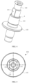
- FIG. 4 is a schematic diagram of a structure of a conductive pillar in FIG. 3
- FIG. 5 is a top view of FIG. 4 .
- the conductive pillar 130 is columnar, and the conductive pillar 130 is conductive.
- the conductive pillar 130 may be made of conductive metal such as iron, copper, or steel.
- the conductive pillar 130 may be of a hollow structure, for example, a through hole is disposed on an axis of the conductive pillar 130, to reduce a weight of the conductive pillar 130, and facilitate mounting and removal of the conductive pillar 130.
- the axis of the conductive pillar 130 overlaps the axis l of the rotor body 110.
- An end of the conductive pillar 130 in this embodiment of this application not representing the invention is grounded. It should be noted that "being grounded” herein may be connected to reference ground or ground.
- an end of the conductive pillar 130 penetrates through one of the ports of the rotor body 110, and is connected to a motor housing 200 of the motor by using a conductive member such as a conductor.
- a conductive member such as a conductor.
- the motor housing 200 of the motor is in contact with a chassis of the vehicle, and the vehicle is on a road, the chassis of the vehicle is in contact with the ground.
- an end of the conductive pillar 130 is connected to the motor housing 200 by using a conductive member such as a conductor, so that the conductive pillar 130 is grounded.
- the motor housing 200 When the motor housing 200 is not in contact with the chassis of the vehicle, namely, when the motor housing 200 and the chassis of the vehicle are spaced apart, because the motor housing 200 is not live, the motor housing 200 may be used as the reference ground. In this way, an end of the conductive pillar 130 is connected to the motor housing 200 of the motor by using a conductive member such as a conductor, to ensure that the conductive pillar 130 accesses the reference ground whose potential is zero.
- the shaft current is first discharged to the outer ring 121 of the conductive bearing 120 by using the rotor body 110, then flows to the conductive pillar 130 sequentially by using the steel ball 122, the conductive grease, and the inner ring 123 of the conductive bearing 120, and is finally discharged by using the conductive pillar 130. Because the conductive pillar 130 is grounded, a resistance of a conductive loop formed from the rotor body 110, the conductive bearing 120, and the conductive pillar 130 to the ground (or the reference ground) is less than a resistance of a conductive loop formed between the rotor body 110 and a main bearing 300.
- the current on the rotor body 110 is mostly transmitted and discharged by using the conductive bearing 120 and the conductive pillar 130, and strength of a current flowing to the main bearing 300 is reduced, so that the main bearing 300 of the motor 100 is prevented from being electrically corroded by the shaft current.
- the conductive bearing 120 is sleeved on the grounded conductive pillar 130, so that the inner ring 123 of the conductive bearing 120 can interference fit with the outer wall of the conductive pillar 130, to enable the inner ring 123 of the conductive bearing 120 to be closely attached to the outer wall of the conductive pillar 130, and avoid the following case:
- the conductive bearing 120 In the high-speed rotation process of the rotor body 110, the conductive bearing 120 is in unstable contact with the conductive pillar 130 because the rotor body 110 drives the conductive bearing 120 to move axially and radially, and consequently the shaft current cannot be discharged.
- the outer ring 121 of the conductive bearing 120 interference fits with the inner wall of the shaft hole 111. This also further improves closeness of contact between the conductive bearing 120 and the rotor body 110, and ensures that the shaft current on the rotor body 110 can be stably transmitted to the conductive bearing 120.
- the motor rotor 100 in this embodiment of this application can ensure that the rotor body 110, the conductive bearing 120, and the conductive pillar 130 are always electrically connected in a running process of the motor rotor 100, to ensure that the shaft current on the rotor body 110 is successfully discharged by using the conductive bearing 120 and the conductive pillar 130.
- the outer wall of the conductive pillar 130 circumferentially abuts on the inner ring 123 of the conductive bearing 120 evenly, so that force is evenly exerted on the conductive bearing 120, and no offset loading force occurs. Therefore, the conductive bearing 120 is prevented from being damaged due to concentrated stress, and the conductive bearing 120 is prevented from being abnormally worn due to the offset loading force, to prevent the conductive grease from overflowing because the sealing rings on the conductive bearing 120 are worn, and prolong a service life of the conductive bearing 120.
- FIG. 6 is a schematic diagram of a structure of a grounding bracket in FIG. 3 .
- the motor rotor 100 in this embodiment of this application may further include a grounding bracket 150.
- the grounding bracket 150 is located at an end of the rotor body 110, one end of the grounding bracket 150 is electrically connected to the conductive pillar 130, and the other end of the grounding bracket 150 is connected to the motor housing 200 of the motor.
- the grounding bracket 150 in this embodiment of this application not representing the invention is specifically close to an end of the rotor body 110 that is provided with the conductive bearing 120, and the grounding bracket 150 is located outside the rotor body 110.
- the grounding bracket 150 is located outside the first end of the rotor body 110.
- the grounding bracket 150 is located outside the second end of the rotor body 110.
- one end of the conductive pillar 130 extends into the shaft hole 111 of the rotor body 110 and fits with the conductive bearing 120, and the other end of the conductive pillar 130 may extend out of the end of the rotor body 110 and is electrically connected to the grounding bracket 150.
- the conductive bearing 120 is adj acent to the first end of the rotor body 110
- an end of the conductive pillar 130 extends out of the first end of the rotor body 110 and is electrically connected to the grounding bracket 150 outside the first end of the rotor body 110.
- the motor in this embodiment of this application when the motor in this embodiment of this application is applied to a vehicle such as an electric vehicle, and the motor housing 200 of the motor is always connected to a chassis of the vehicle, if an end of the conductive pillar 130 is electrically connected to the grounding bracket 150, and the grounding bracket 150 is connected to the motor housing 200 of the motor, the conductive pillar 130 may be electrically connected to the ground by using the grounding bracket 150 and the motor housing 200.
- the motor housing 200 may be directly used as the reference ground whose potential is zero.
- the conductive pillar 130 may be electrically connected, by using the grounding bracket 150, to the reference ground whose potential is zero. Therefore, it is ensured that the shaft current on the conductive pillar 130 can be discharged by using the grounding bracket 150 and the motor housing 200, and a grounding process of the conductive pillar 130 is simplified, to improve assembling efficiency of the motor rotor 100.
- the conductive pillar 130 and the grounding bracket 150 may be electrically connected to each other by using a conductive member.
- the conductive member may be a conductor.
- the motor rotor 100 may further include an elastic conductive member 160.
- the elastic conductive member 160 may be used as a conductive member. One end of the elastic conductive member 160 is electrically connected to the conductive pillar 130, and the other end of the elastic conductive member 160 is electrically connected to the grounding bracket 150.
- one end of the elastic conductive member 160 may be fastened to the conductive pillar 130 through bonding, clamping, screw connection, or the like, and the other end of the elastic conductive member 160 may also be fastened to the grounding bracket 150 through bonding, clamping, screw connection, or the like.
- a composition material of the conductive adhesive may include but is not limited to one or more of an epoxy resin, an acrylic resin, and polyurethane.
- a first mounting hole (not shown in the figure) may be disposed on the elastic conductive member 160, a second mounting hole 1532 that matches the first mounting hole is disposed on the grounding bracket 150, and the elastic conductive member 160 is fastened to the grounding bracket 150 by using a first fastener 170 that passes through the first mounting hole and the second mounting hole 1532.
- the first fastener 170 is specifically a conductive connector.
- the fastener may be a screw, a rivet, or a bolt, to implement an electrical connection between the elastic conductive member 160 and the grounding bracket 150.
- the elastic conductive member 160 may include but is not limited to any one of a rubber member and a silicone member.
- the elastic conductive member 160 may be another elastic conductive member such as a metal spring.
- the grounding bracket 150 may also be fastened to the motor housing 200 through bonding, clamping, screw connection, or the like.
- a third mounting hole 1533 may be disposed on the grounding bracket 150.
- a fourth mounting hole (not shown in the figure) that matches the third mounting hole 1533 is disposed on the motor housing 200.
- the grounding bracket 150 is fastened to the motor housing 200 by using a second fastener 180 that passes through the third mounting hole 1533 and the fourth mounting hole. In this way, stability of a connection between the grounding bracket 150 and the motor housing 200 is ensured, and an assembling structure between the grounding bracket 150 and the motor housing 200 is simplified, to improve assembling efficiency of the motor.
- the second fastener 180 may include but is not limited to a conductive fastener such as a bolt, a screw, or a rivet.
- grounding bracket 150 when the grounding bracket 150 is bonded to the motor housing 200, adhesive used to bond the grounding bracket 150 to the motor housing 200 needs to be conductive adhesive, to ensure that a current path is formed between the grounding bracket 150 and the motor housing 200.
- the elastic conductive member 160 is disposed between the conductive pillar 130 and the grounding bracket 150.
- the elastic conductive member 160 has a length used for cushioning
- the length of the elastic conductive member 160 is adaptively adjusted with movement of the conductive pillar 130, and the elastic conductive member 160 is not torn. Therefore, it is ensured that the electrical connection between the conductive pillar 130 and the grounding bracket 150 is stable.
- the grounding bracket 150 in this embodiment of this application not representing the invention, has a positioning hole 151.
- An end of the conductive pillar 130 may extend out of the end of the rotor body 110 and pass through the positioning hole 151, so that radial movement of the conductive pillar 130 in the rotor body 110 is limited, to improve radial stability of the conductive pillar 130. It should be noted that a radial direction of the rotor body 110 is consistent with a radial direction of the conductive pillar 130.
- the outer wall of the conductive pillar 130 may clearance fit with an inner wall of the positioning hole 151. Therefore, in the high-speed rotation process, the rotor body 110 can drive the conductive bearing 120 and the conductive pillar 130 to move freely. This effectively prevents a rigid connection between the conductive pillar 130 and the grounding bracket 150 from hampering movement of the inner ring 123 of the conductive bearing 120, to ensure that a structure of the conductive bearing 120 is not damaged.
- a limiting structure may be further disposed between the conductive pillar 130 and the positioning hole 151 in this embodiment of this application.
- the limiting structure is used to limit rotation of the conductive pillar 130 around the axis in the positioning hole 151, to ensure circumferential stability of the conductive pillar 130.
- a positioning protrusion may be disposed on a side wall of the conductive pillar 130.
- a positioning groove (not shown in the figure) that matches the positioning protrusion is disposed on the inner wall of the positioning hole 151. After an end of the conductive pillar 130 internally passes through the positioning hole 151, the positioning protrusion extends into the positioning groove.
- the positioning protrusion and the positioning groove are used as the limiting structure to limit rotation of the conductive pillar 130 around the axis of the conductive pillar 130 in the positioning hole 151.
- FIG. 7 is a top view of FIG. 6 .
- at least a partial outer wall of the conductive pillar 130 that is located inside the positioning hole 151 forms a first plane 131 (as shown in FIG. 4 ), and correspondingly, at least a partial inner wall of the positioning hole 151 forms a second plane 1511 (as shown in FIG. 7 ) corresponding to the first plane 131.
- the limiting structure includes the first plane 131 and the second plane 1511.
- the limiting structure is set as a plane on a partial side wall of the conductive pillar 130 that is located inside the positioning hole 151, and a plane on at least a partial inner wall of the positioning hole 151. This effectively prevents the conductive pillar 130 from rotating around the axis l in the positioning hole 151, and also simplifies the limiting structure. Therefore, manufacturing and assembling efficiency of the entire motor rotor 100 are improved.
- a plurality of first planes 131 may be formed on the side wall of the conductive pillar 130, and the plurality of first planes 131 are disposed at intervals around the axis of the conductive pillar 130.
- a plurality of second planes 1511 are formed on the inner wall of the positioning hole 151, the plurality of second planes 1511 are disposed at intervals around an axis of the positioning hole 151, and the plurality of first planes 131 are respectively opposite to the corresponding second planes 1511, to ensure that the conductive pillar 130 does not rotate in the positioning hole 151.
- two first planes 131 may be formed on the side wall of the conductive pillar 130, and the two first planes 131 are disposed oppositely to each other on two sides of the axis of the conductive pillar 130.
- two second planes 1511 are formed on the inner wall of the positioning hole 151, and the two second planes 1511 are disposed oppositely to each other on two sides of the axis of the positioning hole 151.
- An end of the conductive pillar 130 penetrates into the positioning hole 151 of the grounding bracket 150, and one first plane 131 of the conductive pillar 130 fits with one second plane 1511 of the grounding bracket 150, and the other first plane 131 of the conductive pillar 130 fits with the other second plane 1511 of the grounding bracket 150.
- This further improves a limiting effect of the limiting structure on rotation of the conductive pillar 130, and ensures that the conductive pillar 130 does not rotate around the axis during high-speed rotation of the rotor body 110, namely, ensures that the conductive pillar 130 is static in the running process of the motor rotor 100. Therefore, stability of the electrical connection between the conductive pillar 130 and each of the conductive bearing 120 and the grounding bracket 150 is further improved.
- the grounding bracket 150 may include a body part 152 and a connection part 153, the positioning hole 151 is formed on the body part 152, and an end of the conductive pillar 130 penetrates into the positioning hole 151 on the body part 152, to limit radial movement of the conductive pillar 130 in the rotor body 110.
- One end of the connection part 153 is connected to the body part 152, and the other end of the connection part 153 is connected to the motor housing 200.
- connection parts 153 There may be one or more connection parts 153, and the plurality of connection parts 153 are disposed at intervals around an outer periphery of the positioning hole 151.
- connection parts 153 there are N connection parts 153, and N ⁇ 3, namely, there may be at least three connection parts 153.
- the at least three connection parts 153 are disposed at intervals around the outer periphery of the positioning hole 151, one end of each connection part 153 is connected to the body part 152, the other end of each connection part 153 extends in a direction away from the axis of the positioning hole 151, and the other end of each connection part 153 is used to connect to the motor housing 200.
- connection parts 153 may be distributed at intervals on an outer periphery of the body part 152 around the axis of the positioning hole 151, so that lines between points at which the grounding bracket 150 is connected to the motor housing 200 form a triangle, to improve stability of the connection between the grounding bracket 150 and the motor housing 200.
- connection parts 153 may be evenly distributed on the outer periphery of the body part 152, namely, an angle between two adjacent connection parts 153 is 120°, to facilitate manufacturing of the grounding bracket 150.
- the motor housing 200 has three mounting holes. In this way, three connection parts 153 are disposed on an end of the body part 152. This improves strength of the connection between the grounding bracket 150 and the motor housing 200, and fully uses a structure of the motor housing 200.
- the grounding bracket 150 is set as the body part 152 and the connection part 153 connected to an end of the body part 152, and the grounding bracket 150 and the motor housing 200 are stably connected to each other by using the connection part 153. This improves strength of the connection between the grounding bracket 150 and the motor housing 200.
- the positioning hole 151 is disposed on the body part 152 connected to an end of the connection part 153. Therefore, a limiting effect on the conductive pillar 130 is implemented, and structural strength of the grounding bracket 150 is ensured, so that a service life of the grounding bracket 150 is prolonged.
- the third mounting hole 1533 may be disposed at an end of each connection part 153.
- three fourth mounting holes respectively corresponding to the third mounting holes 1533 are disposed on the motor housing 200.
- the second fastener 180 may pass through each pair of third mounting hole 1533 and fourth mounting hole that is coaxial with the third mounting hole 1533, to further improve strength of the connection between the grounding bracket 150 and the motor housing 200.
- an end of the elastic conductive member 160 may be connected to any connection part 153, to improve assembling flexibility of the elastic conductive member 160.
- the second mounting hole 1532 may be disposed on each of the three connection parts 153 of the grounding bracket 150, and the first mounting hole on the elastic conductive member 160 may fit with any second mounting hole 1532. In this way, the first fastener 170 passes through the first mounting hole of the elastic conductive member 160 and the second mounting hole 1532, to fasten an end of the elastic conductive member 160 to the connection part 153.
- the grounding bracket 150 may be an integrally formed member, namely, the main part 152 and the at least three connection parts 153 are integrally injection molded, to improve structural strength of the grounding bracket 150 and simplify an assembling process of the grounding bracket 150.
- an avoidance groove 1531 may be formed on a side of each connection part 153 that faces the rotor body 110, and the avoidance groove 1531 is used to allow an end of the rotor body 110 to enter.
- the rotor body 110 may enter the avoidance groove 1531 without directly colliding with a surface of the connection part 153, to avoid damage to the structure of the grounding bracket 150.
- disposition of the avoidance groove 1531 also prevents the grounding bracket 150 from being interfered by the rotor body 110 in a mounting process.
- the following describes a structure in which the outer ring 121 of the conductive bearing 120 indirectly interference fits with the inner wall of the shaft hole 111.
- FIG. 8 is a schematic diagram of a structure of a bearing housing in FIG. 3
- FIG. 9 is a sectional in the invention view of FIG. 8
- the motor rotor 100 in the invention includes a bearing housing 140.
- the bearing housing 140 is disposed in the shaft hole 111, and the conductive bearing 120 is located in a mounting cavity 141 of the bearing housing 140.
- An outer wall of the bearing housing 140 interference fits with the inner wall of the shaft hole 111, and the outer ring 121 of the conductive bearing 120 interference fits with an inner wall of the bearing housing 140.
- the conductive bearing 120 is fastened in the shaft hole 111 of the rotor body 110 by using the bearing housing 140, and the outer ring 121 of the conductive bearing 120 interference fits with the inner wall of the shaft hole 111 by using a side wall of the bearing housing 140.
- the bearing housing 140, the rotor body 110, and the outer ring 121 of the conductive bearing 120 are static relative to each other.
- the bearing housing 140 and the outer ring 121 of the conductive bearing 120 rotate synchronously with the rotor body 110.
- the bearing housing 140 is disposed in the shaft hole 111, and the conductive bearing 120 is mounted in the bearing housing 140. This facilitates assembling of the conductive bearing 120 in the shaft hole 111 of the rotor body 110, and also improves axial stability of the conductive bearing 120 and the conductive pillar 130 in the shaft hole 111.
- the outer wall of the bearing housing 140 interference fits with the inner wall of the shaft hole 111, and the outer ring 121 of the conductive bearing 120 interference fits with the inner wall of the bearing housing 140, so that the bearing housing 140 is in closer contact with each of the rotor body 110 and the conductive bearing 120. Therefore, it is ensured that the shaft current on the rotor body 110 can be successfully transmitted to the bearing housing 140 and the conductive bearing 120, and assembling stability of the bearing housing 140 in the shaft hole 111 and assembling stability of the conductive bearing 120 in the bearing housing 140 are also improved.
- a cooling path 113 is formed between the outer wall of the bearing housing 140 and the inner wall of the shaft hole 111 in this embodiment of this application.
- the cooling path 113 extends in the axis direction of the rotor body 110, and two ends of the cooling path 113 in an extension direction both communicate with the shaft hole 111 of the rotor body 110.
- the cooling path 113 is used to allow a cooling medium to flow. It may be understood that the cooling medium may be oil or cooling water.
- a groove 144 is disposed on the outer wall of the bearing housing 140, and two ends of the groove 144 run through two ends of the bearing housing 140 in an extension direction.
- an inner wall of the groove 144 and the inner wall of the shaft hole 111 jointly surround the cooling path 113.
- the extension direction of the bearing housing 140 is consistent with the axis direction of the rotor body 110.
- the groove 144 may be a structure integrally injection molded when the bearing housing 140 is manufactured. Certainly, in some examples, cutting may be performed on the outer wall of the manufactured bearing housing 140 to form the groove 144 on a partial side wall.
- a partial outer wall of the bearing housing 140 may be cut into a flat surface, and the flat surface may be considered as the groove 144 with a relatively shallow depth.
- Two sides of the flat surface in a circumferential direction of the bearing housing 140 abut on the inner wall of the shaft hole 111, so that the flat surface and the inner wall of the shaft hole 111 surround the cooling path 113.
- the cooling medium such as oil may be introduced into the shaft hole 111 of the rotor body 110.
- the oil flows from the first end of the rotor body 110 to the shaft hole 111.
- the oil may enter the cooling path 113 from one end of the cooling path 113 to perform heat exchange with the outer wall of the bearing housing 140, is drained from the other end of the cooling path 113 to the shaft hole 111, and is finally drained from the second end of the rotor body 110.
- the conductive bearing 120 and the conductive pillar 130 inside the bearing housing 140 transmit heat to the outer wall of the bearing housing 140 by using the inner wall of the bearing housing 140. In this way, after heat exchange is performed between the oil in the cooling path 113 and the outer wall of the bearing housing 140, heat of the bearing housing 140 and the conductive bearing 120 and the conductive pillar 130 inside the bearing housing 140 may be removed, to dissipate heat for the bearing housing 140, the conductive bearing 120, and the conductive pillar 130.
- the cooling path 113 is formed between the outer wall of the bearing housing 140 and the inner wall of the shaft hole 111.
- the cooling medium that is introduced into the shaft hole 111 may enter the cooling path 113, to cool the bearing housing 140, the conductive bearing 120, and the conductive pillar 130. Therefore, the following case is avoided:
- the conductive bearing 120 is heated and expanded in the high-speed running process of the motor rotor 100, and consequently the steel ball 122 in the conductive bearing 120 cannot rotate normally and a conductivity of the conductive grease decreases. Therefore, it is ensured that the conductive bearing 120 and the conductive grease are stable.
- the bearing housing 140 may include a bearing housing body 142 and a base 143.
- An outer wall of the bearing housing body 142 interference fits with the inner wall of the shaft hole 111.
- the bearing housing body 142 includes a first end and a second end that are disposed oppositely to each other in an extension direction.
- the first end of the bearing housing body 142 faces the grounding bracket 150, and the first end is opened.
- the base 143 of the bearing housing 140 is disposed at the second end of the bearing housing body 142. In other words, a first end of the bearing housing 140 is opened and faces the grounding bracket 150, and a second end of the bearing housing 140 has the base 143.
- the bearing housing body 142 and the base 143 jointly surround the mounting cavity 141 of the bearing housing 140, and the conductive bearing 120 is located in the mounting cavity 141.
- first end and the second end of the bearing housing body 142 may also be considered as the first end and the second end of the bearing housing 140.
- the conductive bearing 120 may be mounted in the bearing housing 140 from an opening of the first end of the bearing housing 140, and an end of the conductive pillar 130 extends into the mounting cavity 141 of the bearing housing 140 through the opening of the first end of the bearing housing 140, and further interference fits with the inner ring 123 of the conductive bearing 120.
- an end of the bearing housing 140 that faces the grounding bracket 150 is opened, to facilitate assembling of the conductive bearing 120 and the conductive pillar 130.
- the base 143 of the bearing housing 140 plays a role of positioning the conductive bearing 120 axially. In other words, provided that the conductive bearing 120 is assembled on the base 143, positioning of the conductive bearing 120 in the bearing housing 140 can be completed. This improves assembling efficiency of the conductive bearing 120.
- An auxiliary hole may be disposed on a side wall of the bearing housing body 142 that is close to the first end.
- the auxiliary hole is used to assist a mounting tool in grasping the bearing housing 140.
- the mounting tool may extend into the auxiliary hole to exert force on the bearing housing 140, so as to build the bearing housing 140 into a corresponding position in the shaft hole 111.
- the mounting tool also extends into the auxiliary hole to grasp the bearing housing 140, so as to quickly pull the bearing housing 140 out of the shaft hole 111.
- the bearing housing 140 in this embodiment of this invention may be an integrally formed member, namely, the bearing housing body 142 and the base 143 of the bearing housing 140 are integrally injection molded, to improve structural strength of the bearing housing 140.
- the bearing housing body 142 and the base 143 are disposed separately is not ruled out.
- the base 143 may be fastened to the second end of the bearing housing body 142 through screw connection, clamping, or the like.
- an inner wall of the base 143 is recessed in a direction away from the first end of the bearing housing body 142 to form a limiting groove 1431, and an end of the conductive pillar 130 extends into the limiting groove 1431 to limit radial movement of the conductive pillar 130 in the rotor body 110.
- An opening size and a shape of the limiting groove 1431 may be respectively consistent with a radial size and a shape of the conductive pillar 130.
- the outer wall of the conductive pillar 130 may be attached to an inner wall of the limiting groove 1431, to further prevent an end of the conductive pillar 130 that faces the base 143 from shaking radially.
- One end of the conductive pillar 130 internally passes through the positioning hole 151 of the grounding bracket 150, and the other end of the conductive pillar 130 extends into the limiting groove 1431 of the bearing housing 140. This effectively limits radial movement of the conductive pillar 130, and prevents the conductive pillar 130 from shaking from side to side radially in the high-speed running process of the rotor body 110.
- a partial region of the base 143 may protrude in a direction away from the first end of the bearing housing body 142.
- a recess part is formed on the inner wall of the base 143.
- the recess part may be used as the limiting groove 1431, and an inner wall of the recess part is the inner wall of the limiting groove 1431.
- a protrusion part is formed on an outer wall of the base 143, and a side wall of the protrusion part may be understood as an outer wall of the limiting groove 1431.
- a groove may be directly disposed on the inner wall of the base 143, and the groove is used as the limiting groove 1431.
- the inner wall (an inner surface) of the base 143 is a surface of the base 143 that is located inside the bearing housing 140
- the outer wall (an outer surface) of the base 143 is a surface of the base 143 that is located outside the bearing housing 140.
- a step part 133 is formed on the side wall of the conductive pillar 130, and the step part 133 is located between the grounding bracket 150 and the base 143 of the motor rotor 100.
- the step part 133 on the conductive pillar 130 is located on a side of the grounding bracket 150 that faces the bearing housing 140.
- a distance between the step part 133 and the grounding bracket 150 is a first distance (shown by h1 in FIG. 3 ).
- a distance between an outer peripheral surface of the limiting groove 1431 and the end of the conductive pillar 130 that faces the base 143 is a second distance (shown by h2 in FIG. 3 ).
- the first distance h1 is specifically a vertical distance between a step surface (shown by a in FIG. 4 ) of the step part 133 that faces the grounding bracket 150 and a surface of the body part 152 that faces the step part 133.
- the second distance h2 is specifically a vertical distance between the outer peripheral surface of the limiting groove 1431 (shown by b in FIG. 3 and FIG. 9 ) and an end face of the conductive pillar 130 that faces the base 143.
- the outer peripheral surface of the limiting groove 1431 is an inner surface of the base 143 that is located outside the limiting groove 1431.
- the first distance h1 is less than the second distance h2. In this way, when one end of the conductive pillar 130 moves axially to the grounding bracket 150 in the high-speed running process of the rotor body 110, the other end of the conductive pillar 130 is still located in the limiting groove 1431 and is not separated from the limiting groove 1431. This reduces a distance by which the conductive pillar 130 moves axially, and ensures axial stability of the conductive pillar 130.
- the second distance h1 is greater than zero, namely, the end of the conductive pillar 130 that faces the base 143 is still located in the limiting groove 1431 of the base 143. Therefore, axial stability of the conductive pillar 130 is ensured, and radial stability of the conductive pillar 130 is also ensured.
- a stop part 132 may extend from the outer wall of the conductive pillar 130 in a direction away from the axis.
- the conductive bearing 120 is located between the stop part 132 and the base 143, and a distance between an end of the stop part 132 and the inner wall of the bearing housing 140 is less than a diameter of the steel ball 122 in the conductive bearing 120.
- the distance between an end of the stopper 132 and the inner wall of the bearing housing 140 is specifically a distance (shown by h3 in FIG. 3 ) between an end of the stop part 132 that is away from the axis of the conductive pillar 130 and the inner wall of the bearing housing 140, where h3 is less than the diameter of the steel ball 122 in the conductive bearing 120.
- h3 is less than the diameter of the steel ball 122 in the conductive bearing 120.
- a boss 112 may be formed on the inner wall of the shaft hole 111, and an end of the bearing housing 140 that is away from the grounding bracket 150 abuts on the boss 112.
- the base 143 of the bearing housing 140 abuts on the boss 112 on the inner wall of the rotor body 110, to further limit axial movement of the bearing housing 140 in the rotor body 110.
- the boss 112 plays a role in quickly positioning assembling of the bearing housing 140 in the shaft hole 111, namely, provided that the bearing housing 140 is placed downwards to abut on the boss 112, positioning of the bearing housing 140 in the shaft hole 111 is completed.
- An embodiment of this invention further provides a motor, including a motor housing 200, a main bearing 300, and the foregoing motor rotor 100.
- the motor housing 200 is sleeved on an outer wall of the motor rotor 100 by using the main bearing 300.
- an inner ring of the main bearing 300 may interference fit with the outer wall of the motor rotor 100, to ensure that the inner ring of the main bearing 300 is in closer contact with the motor rotor 100, and ensure that the inner ring of the main bearing 300 and the motor rotor 100 are static relative to each other.
- an outer ring of the main bearing 300 interference fits with an inner wall of the motor housing 200, to ensure that the outer ring of the main bearing 300 is in closer contact with the motor housing 200, and ensure that the outer ring of the main bearing 300 and the motor housing 200 are static relative to each other.
- the foregoing motor rotor 100 is disposed in the motor, to prevent the main bearing 300 of the motor rotor 100 from being electrically corroded by a shaft current.
- the conductive bearing 120 is prevented from being abnormally worn. Therefore, conductive grease is prevented from overflowing because sealing rings on the conductive bearing 120 are worn, a service life of the conductive bearing 120 is prolonged, it is ensured that the shaft current on the motor rotor 100 is successfully discharged by using the conductive bearing 120, and the main bearing 300 is not electrically corroded, to ensure that the motor runs normally.
- An embodiment of this invention further provides a vehicle, including wheels and the foregoing motor.
- a motor rotor 100 of the motor is connected to the wheels to drive the wheels to rotate.
- a rotation shaft of the motor rotor 100 may be connected to the wheels by using a transmission component, so that the rotation shaft of the motor rotates to output power, the transmission component transmits the power to the wheels, and therefore the wheels rotate.
- the foregoing motor is mounted on the vehicle, so that it is ensured that the motor of the vehicle can work stably, to stably drive the wheels.
- the vehicle in this embodiment of this invention may include but is not limited to any one of an electric vehicle (EV), a battery electric vehicle (PEVBEV), a hybrid electric vehicle (HEV), a range extended electric vehicle (REEV), a plug-in hybrid electric vehicle (PHEV), or a new energy vehicle (new energy vehicle).
- EV electric vehicle
- PEVBEV battery electric vehicle
- HEV hybrid electric vehicle
- REEV range extended electric vehicle
- PHEV plug-in hybrid electric vehicle
- new energy vehicle new energy vehicle
Landscapes
- Engineering & Computer Science (AREA)
- Power Engineering (AREA)
- General Engineering & Computer Science (AREA)
- Mechanical Engineering (AREA)
- Motor Or Generator Frames (AREA)
Description
- Embodiments of this application relate to the field of drive motor technologies, and in particular, to a motor rotor, a motor, and a vehicle.
- A main part of an electric vehicle is an electric drive system, and a power source of the electric drive system is a motor. The motor converts electric energy into mechanical energy, to drive wheels of the electric vehicle to rotate, so as to drive the electric vehicle to travel. In a process in which the motor converts the electric energy into the mechanical energy, a shaft current is generated on a motor rotor. When the shaft current is discharged to a main bearing sleeved on an outer periphery of the motor rotor, the main bearing is electrically corroded. This affects a service life of the main bearing.
- To resolve the foregoing problem, a conductive bearing and a conductive spring are disposed on a conventional motor rotor. The conductive bearing is disposed in a shaft hole of the motor rotor, and an outer ring of the conductive bearing abuts on an inner wall of the shaft hole. In addition, a conductive spring is pressed against an inner ring of the conductive bearing, and the other end of the conductive spring is grounded. In this way, the shaft current on the motor rotor is transmitted and discharged by using the conductive bearing and the conductive spring, and a strength of currents discharged to the main bearing is reduced, so that the main bearing is prevented from being electrically corroded by the shaft current.
- However, in a high-speed running process of the motor rotor, because the conductive bearing moves axially and radially with the motor rotor, the conductive spring cannot be in stable contact with the inner ring of the conductive bearing. As a result, the conductive bearing cannot be stably grounded, and consequently the conductive bearing and the main bearing are both electrically corroded by the shaft current.
-
US 5,914,547 A discloses an auxiliary bearing assembly used to ground the shaft of an electric motor to reduce unwanted currents in the motor bearings. -
US 2018/0083515 A1 discloses an electric motor which includes a case, a stator having stator windings, a rotor having a rotor shaft, and at least one main rotor bearing coupling the rotor shaft to the case. Common mode charge builds up on the rotor due to imbalances of the stator. The at least one main rotor bearing has a first electrical resistance between the rotor shaft and the case. The electric motor further includes a rotor discharge bearing coupling the rotor shaft to the case. The rotor discharge bearing has a second electrical resistance between the rotor shaft and the case that is less than the first electrical resistance, causing the common mode charge to discharge through the rotor discharge bearing. - This invention provides a motor rotor, a motor, and a vehicle, as defined in the appended set of claims, to resolve a problem that a conductive bearing in a conventional motor rotor and a main bearing are both electrically corroded by a shaft current because the conductive bearing cannot be stably grounded, and another potential problem.
- According to the motor rotor provided in this invention, the conductive pillar passes through the inner ring of the conductive bearing, the outer wall of the conductive pillar interference fits with the inner ring of the conductive bearing, and an end of the conductive pillar is grounded. In this way, it is ensured that a shaft current on the rotor body is transmitted and discharged by using the conductive bearing and the conductive pillar, to prevent a main bearing of the motor rotor from being electrically corroded by the shaft current. In addition, the conductive bearing is sleeved on the grounded conductive pillar, so that the inner ring of the conductive bearing can interference fit with the outer wall of the conductive pillar, to enable the inner ring of the conductive bearing to be closely attached to the outer wall of the conductive pillar, and avoid the following case: In a high-speed rotation process of the rotor body, the conductive bearing is in unstable contact with the conductive pillar because the rotor body drives the conductive bearing to move axially and radially, and consequently the shaft current cannot be discharged. In addition, the outer ring of the conductive bearing interference fits with an inner ring of the shaft hole. This also further improves closeness of contact between the conductive bearing and the rotor body, and ensures that the shaft current on the rotor body can be stably transmitted to the conductive bearing. In other words, the motor rotor in this invention can ensure that the rotor body, the conductive bearing, and the conductive pillar are always electrically connected in a running process of the motor rotor, to ensure that the shaft current on the rotor body is successfully discharged by using the conductive bearing and the conductive pillar. In addition, compared with a conventional technology in which a spring is pressed against the inner ring of the conductive bearing, in this invention, the outer wall of the conductive pillar circumferentially abuts on the inner ring of the conductive bearing evenly, so that force is evenly exerted on the conductive bearing, and no offset loading force occurs. Therefore, the conductive bearing is prevented from being damaged due to concentrated stress, and the conductive bearing is prevented from being abnormally worn due to the offset loading force, to prevent conductive grease from overflowing because sealing rings on the conductive bearing are worn, and prolong a service life of the conductive bearing.
- In an application, the motor housing may be used as reference ground whose potential is zero, or may be in contact with a chassis of a vehicle to be indirectly connected to ground. In this application, an end of the conductive pillar is electrically connected to the grounding bracket, and the grounding bracket is connected to the motor housing of the motor. In this way, the conductive pillar may be connected to the motor housing by using the grounding bracket. Therefore, it is ensured that the shaft current on the conductive pillar can be discharged to the motor housing by using the grounding bracket or discharged to the ground by using the motor housing, and a grounding process of the conductive pillar is simplified, to improve assembling efficiency of the motor rotor.
- In one embodiment of the invention, the elastic conductive member is disposed between the conductive pillar and the grounding bracket. When an electrical connection between the conductive pillar and the grounding bracket is implemented, because the elastic conductive member has a length used for cushioning, when the rotor body drives the conductive bearing and the conductive pillar to move axially and radially in the high-speed rotation process, the length of the elastic conductive member is adaptively adjusted with movement of the conductive pillar, and the elastic conductive member is not torn. Therefore, it is ensured that the electrical connection between the conductive pillar and the grounding bracket is stable.
- In one embodiment of the invention, the positioning hole is disposed on the grounding bracket, and an end of the conductive pillar internally passes through the positioning hole of the grounding bracket, so that radial movement of the conductive pillar in the rotor body is limited, to improve radial stability of the conductive pillar. In addition, the outer wall of the conductive pillar clearance fits with the inner wall of the positioning hole. Therefore, in the high-speed rotation process, the rotor body can drive the conductive bearing and the conductive pillar to move freely. This effectively prevents a rigid connection between the conductive pillar and the grounding bracket from hampering movement of the inner ring of the conductive bearing, to ensure that a structure of the conductive bearing is not damaged.
- By means of the limiting structure which is in one embodiment of the invention between the conductive pillar and the positioning hole and which is used to limit rotation of the conductive pillar around an axis in the positioning hole, circumferential stability of the conductive pillar can be ensured. In this way, stability of contact between the conductive pillar and the inner ring of the conductive bearing is ensured, and stability of the electrical connection between the conductive pillar and the grounding bracket is ensured.
- In one embodiment of the invention, the limiting structure is set as a plane on a partial side wall of the conductive pillar that is located inside the positioning hole, and a plane on at least a partial inner wall of the positioning hole. This effectively prevents the conductive pillar from rotating circumferentially in the positioning hole, and also simplifies the limiting structure. Therefore, manufacturing and assembling efficiency of the entire motor rotor are improved.
- In one embodiment of the invention, the connection part is disposed on the grounding bracket, and the grounding bracket and the motor housing are stably connected to each other by using the connection part. This improves strength of a connection between the grounding bracket and the motor housing. In addition, the positioning hole is disposed on the body part connected to an end of the connection part. Therefore, a limiting effect on the conductive pillar is implemented, and structural strength of the grounding bracket is ensured, so that a service life of the grounding bracket is prolonged.
- In one embodiment of the invention, the motor housing has three mounting holes, and at least three connection parts are disposed on the body part of the grounding bracket. In this way, this improves strength of the connection between the grounding bracket and the motor housing, and fully uses a structure of the motor housing.
- In one embodiment of the invention, the avoidance groove is disposed on the connection part. In this way, when the rotor body moves axially in a direction of the connection part in the high-speed running process, the rotor body may enter the avoidance groove without directly colliding with a surface of the connection part, to avoid damage to a structure of the grounding bracket. In addition, disposition of the avoidance groove also prevents the grounding bracket from being interfered by the rotor body in a mounting process.
- In this invention, the bearing housing is disposed in the shaft hole, and the conductive bearing is mounted in the bearing housing. This facilitates assembling of the conductive bearing into the shaft hole of the rotor body, and also improves axial stability of the conductive bearing and the conductive pillar in the shaft hole. In addition, the outer wall of the bearing housing interference fits with the inner wall of the shaft hole, and the outer ring of the conductive bearing interference fits with the inner wall of the bearing housing, so that the bearing housing is in closer contact with each of the rotor body and the conductive bearing. Therefore, it is ensured that the shaft current on the rotor body can be successfully transmitted to the bearing housing and the conductive bearing, and assembling stability of the bearing housing in the shaft hole and assembling stability of the conductive bearing in the bearing housing are also improved.
- In one embodiment of the invention, the cooling path is formed between the outer wall of the bearing housing and the inner wall of the shaft hole. In this way, the cooling medium that is introduced into the shaft hole may enter the cooling path, to cool the bearing housing, the conductive bearing, and the conductive pillar. Therefore, the following case is avoided: The conductive bearing is heated and expanded in the high-speed running process of the motor rotor, and consequently a steel ball in the conductive bearing cannot rotate normally and a conductivity of the conductive grease decreases. Therefore, it is ensured that the conductive bearing and the conductive grease are stable.
- In one embodiment of the invention, an end of the bearing housing that faces the grounding bracket is opened, to facilitate assembling of the conductive bearing and the conductive pillar. In addition, the base of the bearing housing plays a role of positioning the conductive bearing axially. In other words, provided that the conductive bearing is assembled on the base, positioning of the conductive bearing in the bearing housing can be completed. This improves assembling efficiency of the conductive bearing.
- When one end of the conductive pillar moves axially to the grounding bracket in the high-speed running process of the rotor body, the other end of the conductive pillar is still located in the limiting groove and is not separated from the limiting groove. This reduces a distance by which the conductive pillar moves axially, and ensures axial stability of the conductive pillar.
- It is ensured that the steel ball in the conductive bearing does not drop between the stop part and the inner wall of the bearing housing, and ensured that the steel ball does not drop from the first end of the bearing housing to the outside of the rotor body.
- By means of the boss which is formed on the inner wall of the shaft hole, and by means of the end of the bearing housing that is away from the grounding bracket abutting on the boss, axial movement of the bearing housing in the rotor body is further limited. In addition, the boss plays a role in quickly positioning assembling of the bearing housing in the shaft hole, namely, provided that the bearing housing is placed downwards to abut on the boss, positioning of the bearing housing in the shaft hole is completed.
- In this one embodiment of the invention, the motor rotor is disposed in the motor, to prevent the main bearing of the motor from being electrically corroded by a shaft current. In addition, because no concentrated stress occurs in a conductive bearing of the motor rotor, and the conductive bearing is not subject to offset loading force, the conductive bearing is prevented from being abnormally worn. Therefore, conductive grease is prevented from overflowing because sealing rings on the conductive bearing are worn, a service life of the conductive bearing is prolonged, it is ensured that the shaft current on the motor rotor is discharged by using the conductive bearing, and the main bearing is not electrically corroded, to ensure that the motor runs normally.
- In one embodiment of the invention, the motor is mounted on the vehicle, so that it is ensured that the motor of the vehicle can work stably, to stably drive the wheels.
-
-
FIG. 1 is a schematic diagram of a structure of a motor according to an embodiment; -
FIG. 2 is a partially enlarged view of I inFIG. 1 ; -
FIG. 3 is a schematic diagram of a structure of a part inFIG. 2 ; -
FIG. 4 is a schematic diagram of a structure of a conductive pillar inFIG. 3 ; -
FIG. 5 is a top view ofFIG. 4 ; -
FIG. 6 is a schematic diagram of a structure of a grounding bracket inFIG. 3 ; -
FIG. 7 is a top view ofFIG. 6 ; -
FIG. 8 is a schematic diagram of a structure of a bearing housing inFIG. 3 ; and -
FIG. 9 is a sectional view ofFIG. 8 . - Description of reference numerals:
100: motor rotor; 200: motor housing; 300: main bearing; 110: rotor body; 120: conductive bearing; 130: conductive pillar; 140: bearing housing; 150: grounding bracket; 160: elastic conductive member; 170: first fastener; 180: second fastener; 190: motor shaft; 111: shaft hole; 112: boss; 113: cooling path; 121: outer ring; 122: steel ball; 123: inner ring; 131: first plane; 132: stop part; 133: step part; 141: mounting cavity; 142: bearing housing body; 143: base; 144: groove; 151: positioning hole; 152: body part; 153: connection part; 1431: limiting groove; 1511: second plane; 1531: avoidance groove; 1532: second mounting hole; 1533: third mounting hole. - Terms used in embodiments of this application are merely used to explain specific embodiments of this application, but are not intended to limit this application.
-
FIG. 1 is a schematic diagram of a structure of a motor according to an embodiment of this application, andFIG. 2 is a partially enlarged view of I inFIG. 1 . Refer toFIG. 1 andFIG. 2 . In a conventional technology, the motor includes amotor rotor 100 and a stator, the stator is movably sleeved on an outer periphery of themotor rotor 100, and themotor rotor 100 is connected to loads such as wheels. Themotor rotor 100 includes amotor shaft 190, an iron core and an excitation winding that are sleeved on the motor shaft, and the like. Themotor shaft 190 of themotor rotor 100 is connected to loads such as wheels, to drive, when themotor shaft 190 rotates, the wheels to rotate. - During working, the stator generates a rotating magnetic field in an air gap between the stator and the
motor rotor 100. When a direct current is applied to the excitation winding of themotor rotor 100, a static magnetic field with constant polarity is generated. Under an action of armature reaction, themotor rotor 100 generates a torque relative to the stator, so that themotor shaft 190 drives loads such as wheels to move. - In actual application, the stator of the motor includes at least a
motor housing 200. In this embodiment of this application, themotor housing 200 of the motor is mainly used as the stator of the motor. The following specifically describes a structure of the motor by using themotor housing 200 as the stator. - Specifically, the
motor housing 200 and themotor rotor 100 are movably connected to each other by using amain bearing 300. For example, an outer ring of themain bearing 300 interference fits with an inner wall of themotor housing 200, and an inner ring of themain bearing 300 interference fits with an outer wall of themotor rotor 100 such as themotor shaft 190. Therefore, in a high-speed running process of themotor rotor 100, themotor housing 200 can maintain static under an action of themain bearing 300, to ensure that themotor rotor 100 rotates stably around an axis l in themotor housing 200. - It should be noted that, as shown in
FIG. 1 , the axis l is specifically an axis of themotor rotor 100. - Refer to
FIG. 2 . When a PWM inverter supplies power to the excitation winding of themotor rotor 100, a high-frequency common-mode voltage is generated. The high-frequency common-mode voltage is coupled to themotor rotor 100 by using parasitic capacitance of the motor, to form a shaft voltage. When the shaft voltage exceeds a breakdown voltage threshold of an oil film on themotor rotor 100, a shaft current is formed on themotor rotor 100. When the shaft current is discharged to themain bearing 300 on the outer periphery of themotor rotor 100, partial discharging is performed between a steel ball and a race of themain bearing 300, and an electric fusion pit is formed on the race. Consequently, themain bearing 300 is electrically corroded, and a service life of themain bearing 300 is affected. - To prevent the
main bearing 300 from being electrically corroded by the shaft current, aconductive bearing 120 and a conductive spring (not shown in the figure) are disposed on theconventional motor rotor 100. Theconductive bearing 120 is disposed in ashaft hole 111 of themotor rotor 100, and theconductive bearing 120 is close to an end of themotor rotor 100. Anouter ring 121 of theconductive bearing 120 abuts on an inner wall of theshaft hole 111. In addition, a conductive spring is pressed against aninner ring 123 of theconductive bearing 120, and the other end of the conductive spring is grounded. For example, the other end of the conductive spring may be connected to ground or reference ground (for example, the motor housing 200). In this way, a resistance of a conductive loop formed from themotor rotor 100, theconductive bearing 120, and the conductive spring to the ground (or the reference ground) is less than a resistance of a conductive loop formed between themotor rotor 100 and themain bearing 300. Therefore, the shaft current on themotor rotor 100 is mostly transmitted and discharged by using theconductive bearing 120 and the conductive spring, and strength of a current discharged to themain bearing 300 is reduced, so that themain bearing 300 is prevented from being electrically corroded by the shaft current. - In actual application, a difference between the
conductive bearing 120 and themain bearing 300 lies in that theconductive bearing 120 further includes two sealing rings (not shown in the figure) disposed oppositely to each other between theouter ring 121 and theinner ring 123. There is a gap between theouter ring 121 and theinner ring 123, and the two sealing rings each are disposed between two ends of theouter ring 121 and theinner ring 123 in an axis direction (namely, a thickness direction), namely, the two sealing rings each are disposed in gaps on two sides of theconductive bearing 120 in the axis direction (namely, the thickness direction). Asteel ball 122 in theconductive bearing 120 is sealed between the two sealing rings, and conductive grease (not shown in the figure) is filled in a gap between thesteel ball 122 and each of theouter ring 121 and theinner ring 123. The shaft current discharged from themotor rotor 100 to theouter ring 121 of theconductive bearing 120 may be transmitted quickly to theinner ring 123 by using the conductive grease and thesteel ball 122, so that a conductive property of theconductive bearing 120 is improved. - Under an action of elastic force, a tongue of the conductive spring is pressed against a surface that is of the
inner ring 123 of theconductive bearing 120 and that faces away from theouter ring 121. In this way, the current on themotor rotor 100 is transmitted to the conductive spring sequentially by using theouter ring 121, the conductive grease, thesteel ball 122, and theinner ring 123 of theconductive bearing 120, and is finally discharged to the ground or the reference ground by using the conductive spring. - However, a surface of the
inner ring 123 of theconductive bearing 120 is a curved surface, and a surface of the tongue of the conductive spring is a flat surface. When the tongue of the conductive spring is pressed against theinner ring 123 of theconductive bearing 120, two ends of the tongue only in a width direction are in contact with the surface of theinner ring 123, namely, the conductive spring is in linear contact with theinner ring 123 of theconductive bearing 120. In this case, in the high-speed running process of themotor rotor 100, theconductive bearing 120 moves axially and radially with themotor rotor 100, and the conductive spring cannot be in stable contact with theinner ring 123 of theconductive bearing 120. Consequently, theconductive bearing 120 cannot be stably grounded, and both theconductive bearing 120 and themain bearing 300 are electrically corroded by the shaft current. - In addition, because a point at which the conductive spring is pressed against the
conductive bearing 120 is not in a diameter direction of thesteel ball 122, namely, force exerted between the conductive spring and theconductive bearing 120 deviates from the diameter direction of thesteel ball 122, theconductive bearing 120 is subject to offset loading force. The offset loading force causes theinner ring 123 of theconductive bearing 120 to be skewed, and consequently the gap between theinner ring 123 and theouter ring 121 is not equal at all circumferential positions. As a result, theinner ring 123, thesteel ball 122, theouter ring 121, and the like of theconductive bearing 120 are abnormally worn, and the two sealing rings on theconductive bearing 120 in the thickness direction are also worn due to uneven force. Consequently, the conductive grease in theconductive bearing 120 overflows from the two sides of theconductive bearing 120 to affect a service life and the conductive property of theconductive bearing 120. - The embodiments of this application provide a motor rotor, a motor, and a vehicle. A conductive pillar passes through an inner ring of a conductive bearing, an outer wall of the conductive pillar interference fits with the inner ring of the conductive bearing, and an end of the conductive pillar is grounded. In this way, it is ensured that a shaft current on a rotor body is transmitted and discharged by using the conductive bearing and the conductive pillar, to prevent a main bearing of the motor from being electrically corroded by the shaft current. In addition, the conductive bearing is sleeved on the grounded conductive pillar, so that the inner ring of the conductive bearing can interference fit with the outer wall of the conductive pillar, to enable the inner ring of the conductive bearing to be closely attached to the outer wall of the conductive pillar, and avoid the following case: In a high-speed rotation process of the rotor body, the conductive bearing is in unstable contact with the conductive pillar because the rotor body drives the conductive bearing to move axially and radially, and consequently the shaft current cannot be discharged. In addition, an outer ring of the conductive bearing interference fits with an inner ring of a shaft hole. This also further improves closeness of contact between the conductive bearing and the rotor body, and ensures that the shaft current on the rotor body can be stably transmitted to the conductive bearing. In other words, the motor rotor in the embodiments of this application can ensure that the rotor body, the conductive bearing, and the conductive pillar are always electrically connected in a running process of the motor rotor, to ensure that the shaft current on the rotor body is transmitted and discharged by using the conductive bearing and the conductive pillar. In addition, compared with the conventional technology in which the spring is pressed against the inner ring of the conductive bearing, in the embodiments of this application, the outer wall of the conductive pillar circumferentially abuts on the inner ring of the conductive bearing evenly, so that force is evenly exerted on the conductive bearing, and no offset loading force occurs. Therefore, the conductive bearing is prevented from being damaged due to concentrated stress, and the conductive bearing is prevented from being abnormally worn due to the offset loading force, to prevent the conductive grease from overflowing because the sealing rings on the conductive bearing are worn, and prolong the service life of the conductive bearing.
- The following describes in detail specific structures of the motor rotor, the motor, and the vehicle that are provided in the embodiments of this application.
-
FIG. 3 is a schematic diagram of a structure of a part inFIG. 2 . Refer toFIG. 1 to FIG. 3 . Amotor rotor 100 in an embodiment of this application includes arotor body 110, aconductive bearing 120, and aconductive pillar 130. - Refer to
FIG. 1 . In actual application, therotor body 110 includes amotor shaft 190, an iron core and an excitation winding that are sleeved on themotor shaft 190, and the like. A component such as the iron core and the excitation winding is sleeved on a partial outer wall of themotor shaft 190. For example, two ends of themotor shaft 190 in an axis direction extend out of two end faces of the iron core. In this way, the component such as the iron core and the excitation winding does not exist on partial outer walls of themotor shaft 190 that are close to the two ends. - Refer to
FIG. 1 andFIG. 2 . Therotor body 110 in this embodiment of this application hasshaft hole 111 extending in an axis direction. Theshaft hole 111 is specifically disposed on an axis l of therotor body 110, and two ends of theshaft hole 111 penetrate through two end faces of therotor body 110 in the axis direction. For example, theshaft hole 111 is disposed in themotor shaft 190 of therotor body 110, and theshaft hole 111 extends to two end faces of themotor shaft 190 along the axis l of themotor shaft 190. Theconductive bearing 120 is built in theshaft hole 111. - For ease of description, two ends of the
rotor body 110 that are disposed oppositely to each other in an extension direction may be respectively used as a first end of therotor body 110 and a second end of therotor body 110. - It may be understood that there may be one or two
conductive bearings 120 in this embodiment of this application. When there is oneconductive bearing 120, theconductive bearing 120 may be built in theshaft hole 111, and theconductive bearing 120 is close to one of the ports of therotor body 110. For example, theconductive bearing 120 is close to the first end of therotor body 110, namely, theconductive bearing 120 is located in a part of themotor shaft 190 that extends out of the iron core. - When there are two
conductive bearings 120, the twoconductive bearings 120 are respectively built in therotor body 110, and are close to the two ports of therotor body 110. For example, one of theconductive bearings 120 is close to the first end of therotor body 110, and the otherconductive bearing 120 is close to the second end of therotor body 110, namely, the twoconductive bearings 120 are respectively built in two ends of themotor shaft 190 that extend into the iron core. - In this embodiment of this application, a quantity of
conductive bearings 120 is specifically not limited, and may be specifically adjusted based on an actual requirement. - Refer to
FIG. 3 . In actual application, theconductive bearing 120 includes aninner ring 123, asteel ball 122, anouter ring 121, two sealing rings (not shown in the figure), and conductive grease (not shown in the figure). Theouter ring 121 is sleeved on an outer periphery of theinner ring 123, thesteel ball 122 and the conductive grease are located in a gap (which may also be referred to as a race) between theouter ring 121 and theinner ring 123, and the two sealing rings each are disposed between two ends of theouter ring 121 and theinner ring 123 in an axis direction (namely, a thickness direction), so that thesteel ball 122 and the conductive grease of theconductive bearing 120 are sealed between the two sealing rings. A shaft current discharged from themotor rotor 100 to theouter ring 121 of theconductive bearing 120 may be quickly transmitted to theinner ring 123 by using the conductive grease and thesteel ball 122, to improve a conductive property of theconductive bearing 120. - For a specific structure of the
conductive bearing 120, refer to a conventional technology directly. Details are not described herein again. - Still refer to
FIG. 3 . Theouter ring 121 of theconductive bearing 120 interference fits with an inner wall of theshaft hole 111, theconductive pillar 130 internally passes through theconductive bearing 120, and theinner ring 123 of theconductive bearing 120 interference fits with an outer wall of theconductive pillar 130. The inner wall of theshaft hole 111 may be understood as an inner wall of therotor body 110. - It may be understood that, in an implementation not representing the invention, the
outer ring 121 of theconductive bearing 120 directly interference fits with the inner wall of theshaft hole 111, namely, theouter ring 121 of theconductive bearing 120 is in direct contact with the inner wall of theshaft hole 111. - In the invention, the
outer ring 121 of theconductive bearing 120 indirectly interference fits with the inner wall of theshaft hole 111, namely, theouter ring 121 of theconductive bearing 120 is in indirect contact with the inner wall of the shaft hole 111 (as shown inFIG. 3 , for details, refer to a manner that is mentioned below and in which interference fitting between theouter ring 121 of theconductive bearing 120 and the inner wall of theshaft hole 111 is implemented by using a side wall of a bearing housing 140). - The following first describes a structure not representing the invention in which the
outer ring 121 of theconductive bearing 120 directly interference fits with the inner wall of theshaft hole 111. - The
rotor body 110 in this embodiment of this application not representing the invention and theouter ring 121 of theconductive bearing 120 are static relative to each other. For example, in a process in which therotor body 110 rotates around the axis at a high speed, theouter ring 121 of theconductive bearing 120 rotates synchronously with therotor body 110. In addition, theinner ring 123 of theconductive bearing 120 and theconductive pillar 130 are static relative to each other. -
FIG. 4 is a schematic diagram of a structure of a conductive pillar inFIG. 3 , andFIG. 5 is a top view ofFIG. 4 . Refer toFIG. 3 to FIG. 5 . Theconductive pillar 130 is columnar, and theconductive pillar 130 is conductive. For example, theconductive pillar 130 may be made of conductive metal such as iron, copper, or steel. In addition, theconductive pillar 130 may be of a hollow structure, for example, a through hole is disposed on an axis of theconductive pillar 130, to reduce a weight of theconductive pillar 130, and facilitate mounting and removal of theconductive pillar 130. - It may be understood that, after the
conductive pillar 130 is assembled on therotor body 110, the axis of theconductive pillar 130 overlaps the axis l of therotor body 110. - An end of the
conductive pillar 130 in this embodiment of this application not representing the invention is grounded. It should be noted that "being grounded" herein may be connected to reference ground or ground. - For example, an end of the
conductive pillar 130 penetrates through one of the ports of therotor body 110, and is connected to amotor housing 200 of the motor by using a conductive member such as a conductor. In actual application, when the motor in this embodiment of this application is applied to a vehicle, themotor housing 200 of the motor is in contact with a chassis of the vehicle, and the vehicle is on a road, the chassis of the vehicle is in contact with the ground. In this case, an end of theconductive pillar 130 is connected to themotor housing 200 by using a conductive member such as a conductor, so that theconductive pillar 130 is grounded. - When the
motor housing 200 is not in contact with the chassis of the vehicle, namely, when themotor housing 200 and the chassis of the vehicle are spaced apart, because themotor housing 200 is not live, themotor housing 200 may be used as the reference ground. In this way, an end of theconductive pillar 130 is connected to themotor housing 200 of the motor by using a conductive member such as a conductor, to ensure that theconductive pillar 130 accesses the reference ground whose potential is zero. - When a shaft current is generated on the
motor rotor 100, the shaft current is first discharged to theouter ring 121 of theconductive bearing 120 by using therotor body 110, then flows to theconductive pillar 130 sequentially by using thesteel ball 122, the conductive grease, and theinner ring 123 of theconductive bearing 120, and is finally discharged by using theconductive pillar 130. Because theconductive pillar 130 is grounded, a resistance of a conductive loop formed from therotor body 110, theconductive bearing 120, and theconductive pillar 130 to the ground (or the reference ground) is less than a resistance of a conductive loop formed between therotor body 110 and amain bearing 300. Therefore, the current on therotor body 110 is mostly transmitted and discharged by using theconductive bearing 120 and theconductive pillar 130, and strength of a current flowing to themain bearing 300 is reduced, so that themain bearing 300 of themotor 100 is prevented from being electrically corroded by the shaft current. - In this embodiment of this application, not representing the invention, the
conductive bearing 120 is sleeved on the groundedconductive pillar 130, so that theinner ring 123 of theconductive bearing 120 can interference fit with the outer wall of theconductive pillar 130, to enable theinner ring 123 of theconductive bearing 120 to be closely attached to the outer wall of theconductive pillar 130, and avoid the following case: In the high-speed rotation process of therotor body 110, theconductive bearing 120 is in unstable contact with theconductive pillar 130 because therotor body 110 drives theconductive bearing 120 to move axially and radially, and consequently the shaft current cannot be discharged. - In addition, the
outer ring 121 of theconductive bearing 120 interference fits with the inner wall of theshaft hole 111. This also further improves closeness of contact between theconductive bearing 120 and therotor body 110, and ensures that the shaft current on therotor body 110 can be stably transmitted to theconductive bearing 120. In other words, themotor rotor 100 in this embodiment of this application can ensure that therotor body 110, theconductive bearing 120, and theconductive pillar 130 are always electrically connected in a running process of themotor rotor 100, to ensure that the shaft current on therotor body 110 is successfully discharged by using theconductive bearing 120 and theconductive pillar 130. - In addition, compared with the conventional technology in which the conductive spring is pressed against the
inner ring 123 of theconductive bearing 120, in this embodiment of this application, the outer wall of theconductive pillar 130 circumferentially abuts on theinner ring 123 of theconductive bearing 120 evenly, so that force is evenly exerted on theconductive bearing 120, and no offset loading force occurs. Therefore, theconductive bearing 120 is prevented from being damaged due to concentrated stress, and theconductive bearing 120 is prevented from being abnormally worn due to the offset loading force, to prevent the conductive grease from overflowing because the sealing rings on theconductive bearing 120 are worn, and prolong a service life of theconductive bearing 120. -
FIG. 6 is a schematic diagram of a structure of a grounding bracket inFIG. 3 . Refer toFIG. 3 andFIG. 6 . To facilitate grounding of an end of theconductive pillar 130, themotor rotor 100 in this embodiment of this application may further include agrounding bracket 150. Thegrounding bracket 150 is located at an end of therotor body 110, one end of thegrounding bracket 150 is electrically connected to theconductive pillar 130, and the other end of thegrounding bracket 150 is connected to themotor housing 200 of the motor. - The
grounding bracket 150 in this embodiment of this application not representing the invention is specifically close to an end of therotor body 110 that is provided with theconductive bearing 120, and thegrounding bracket 150 is located outside therotor body 110. For example, when theconductive bearing 120 is adjacent to the first end of therotor body 110, thegrounding bracket 150 is located outside the first end of therotor body 110. Correspondingly, when theconductive bearing 120 is adjacent to the second end of therotor body 110, thegrounding bracket 150 is located outside the second end of therotor body 110. - During specific disposition, one end of the
conductive pillar 130 extends into theshaft hole 111 of therotor body 110 and fits with theconductive bearing 120, and the other end of theconductive pillar 130 may extend out of the end of therotor body 110 and is electrically connected to thegrounding bracket 150. For example, when theconductive bearing 120 is adj acent to the first end of therotor body 110, an end of theconductive pillar 130 extends out of the first end of therotor body 110 and is electrically connected to thegrounding bracket 150 outside the first end of therotor body 110. - It may be learned from the foregoing that, when the motor in this embodiment of this application is applied to a vehicle such as an electric vehicle, and the
motor housing 200 of the motor is always connected to a chassis of the vehicle, if an end of theconductive pillar 130 is electrically connected to thegrounding bracket 150, and thegrounding bracket 150 is connected to themotor housing 200 of the motor, theconductive pillar 130 may be electrically connected to the ground by using thegrounding bracket 150 and themotor housing 200. When themotor housing 200 and the chassis of the vehicle are spaced apart, themotor housing 200 may be directly used as the reference ground whose potential is zero. In this way, theconductive pillar 130 may be electrically connected, by using thegrounding bracket 150, to the reference ground whose potential is zero. Therefore, it is ensured that the shaft current on theconductive pillar 130 can be discharged by using thegrounding bracket 150 and themotor housing 200, and a grounding process of theconductive pillar 130 is simplified, to improve assembling efficiency of themotor rotor 100. - The
conductive pillar 130 and thegrounding bracket 150 may be electrically connected to each other by using a conductive member. The conductive member may be a conductor. - Refer to
FIG. 3 . In some examples, themotor rotor 100 may further include an elasticconductive member 160. The elasticconductive member 160 may be used as a conductive member. One end of the elasticconductive member 160 is electrically connected to theconductive pillar 130, and the other end of the elasticconductive member 160 is electrically connected to thegrounding bracket 150. - During specific connection, one end of the elastic
conductive member 160 may be fastened to theconductive pillar 130 through bonding, clamping, screw connection, or the like, and the other end of the elasticconductive member 160 may also be fastened to thegrounding bracket 150 through bonding, clamping, screw connection, or the like. - It should be noted that, when the elastic
conductive member 160 is bonded to theconductive pillar 130, adhesive used to bond the elasticconductive member 160 to theconductive pillar 130 needs to be conductive adhesive, to ensure that a current path is formed between theconductive pillar 130 and the elasticconductive member 160. For example, a composition material of the conductive adhesive may include but is not limited to one or more of an epoxy resin, an acrylic resin, and polyurethane. - An example in which the elastic
conductive member 160 is electrically connected to thegrounding bracket 150 is used. Refer toFIG. 3 andFIG. 6 . A first mounting hole (not shown in the figure) may be disposed on the elasticconductive member 160, asecond mounting hole 1532 that matches the first mounting hole is disposed on thegrounding bracket 150, and the elasticconductive member 160 is fastened to thegrounding bracket 150 by using afirst fastener 170 that passes through the first mounting hole and thesecond mounting hole 1532. It may be understood that thefirst fastener 170 is specifically a conductive connector. For example, the fastener may be a screw, a rivet, or a bolt, to implement an electrical connection between the elasticconductive member 160 and thegrounding bracket 150. - The elastic
conductive member 160 may include but is not limited to any one of a rubber member and a silicone member. For example, the elasticconductive member 160 may be another elastic conductive member such as a metal spring. - In addition, the
grounding bracket 150 may also be fastened to themotor housing 200 through bonding, clamping, screw connection, or the like. For example, as shown inFIG. 3 andFIG. 6 , athird mounting hole 1533 may be disposed on thegrounding bracket 150. Correspondingly, a fourth mounting hole (not shown in the figure) that matches thethird mounting hole 1533 is disposed on themotor housing 200. Thegrounding bracket 150 is fastened to themotor housing 200 by using asecond fastener 180 that passes through thethird mounting hole 1533 and the fourth mounting hole. In this way, stability of a connection between the groundingbracket 150 and themotor housing 200 is ensured, and an assembling structure between the groundingbracket 150 and themotor housing 200 is simplified, to improve assembling efficiency of the motor. - The
second fastener 180 may include but is not limited to a conductive fastener such as a bolt, a screw, or a rivet. - It should be noted that, when the
grounding bracket 150 is bonded to themotor housing 200, adhesive used to bond thegrounding bracket 150 to themotor housing 200 needs to be conductive adhesive, to ensure that a current path is formed between the groundingbracket 150 and themotor housing 200. - In this embodiment of this application, not representing the invention, the elastic
conductive member 160 is disposed between theconductive pillar 130 and thegrounding bracket 150. When an electrical connection between theconductive pillar 130 and thegrounding bracket 150 is implemented, because the elasticconductive member 160 has a length used for cushioning, when therotor body 110 drives theconductive bearing 120 and theconductive pillar 130 to move axially and radially in the high-speed rotation process, the length of the elasticconductive member 160 is adaptively adjusted with movement of theconductive pillar 130, and the elasticconductive member 160 is not torn. Therefore, it is ensured that the electrical connection between theconductive pillar 130 and thegrounding bracket 150 is stable. - Still refer to
FIG. 3 andFIG. 6 . Thegrounding bracket 150 in this embodiment of this application, not representing the invention, has apositioning hole 151. An end of theconductive pillar 130 may extend out of the end of therotor body 110 and pass through thepositioning hole 151, so that radial movement of theconductive pillar 130 in therotor body 110 is limited, to improve radial stability of theconductive pillar 130. It should be noted that a radial direction of therotor body 110 is consistent with a radial direction of theconductive pillar 130. In this case, when theconductive pillar 130 internally passes through thepositioning hole 151 of thegrounding bracket 150, radial movement of theconductive pillar 130 relative to theconductive pillar 130 is also correspondingly limited, to prevent theconductive pillar 130 from shaking from side to side or deviating. - The outer wall of the
conductive pillar 130 may clearance fit with an inner wall of thepositioning hole 151. Therefore, in the high-speed rotation process, therotor body 110 can drive theconductive bearing 120 and theconductive pillar 130 to move freely. This effectively prevents a rigid connection between theconductive pillar 130 and thegrounding bracket 150 from hampering movement of theinner ring 123 of theconductive bearing 120, to ensure that a structure of theconductive bearing 120 is not damaged. - To further improve stability of the
conductive pillar 130, a limiting structure may be further disposed between theconductive pillar 130 and thepositioning hole 151 in this embodiment of this application. The limiting structure is used to limit rotation of theconductive pillar 130 around the axis in thepositioning hole 151, to ensure circumferential stability of theconductive pillar 130. In this way, stability of contact between theconductive pillar 130 and theinner ring 123 of theconductive bearing 120 is ensured, and stability of the electrical connection between theconductive pillar 130 and thegrounding bracket 150 is ensured, to avoid the following case: When theconductive pillar 130 rotates around the axis of theconductive pillar 130, an end of a conductive member such as the elasticconductive member 160 or a conductor is separated from theconductive pillar 130. - In a feasible implementation, a positioning protrusion (not shown in the figure) may be disposed on a side wall of the
conductive pillar 130. Correspondingly, a positioning groove (not shown in the figure) that matches the positioning protrusion is disposed on the inner wall of thepositioning hole 151. After an end of theconductive pillar 130 internally passes through thepositioning hole 151, the positioning protrusion extends into the positioning groove. In this example, the positioning protrusion and the positioning groove are used as the limiting structure to limit rotation of theconductive pillar 130 around the axis of theconductive pillar 130 in thepositioning hole 151. -
FIG. 7 is a top view ofFIG. 6 . Refer toFIG. 3 ,FIG. 4 , andFIG. 7 . In another feasible implementation, at least a partial outer wall of theconductive pillar 130 that is located inside thepositioning hole 151 forms a first plane 131 (as shown inFIG. 4 ), and correspondingly, at least a partial inner wall of thepositioning hole 151 forms a second plane 1511 (as shown inFIG. 7 ) corresponding to thefirst plane 131. The limiting structure includes thefirst plane 131 and thesecond plane 1511. - In this embodiment of this application, not representing the invention, the limiting structure is set as a plane on a partial side wall of the
conductive pillar 130 that is located inside thepositioning hole 151, and a plane on at least a partial inner wall of thepositioning hole 151. This effectively prevents theconductive pillar 130 from rotating around the axis l in thepositioning hole 151, and also simplifies the limiting structure. Therefore, manufacturing and assembling efficiency of theentire motor rotor 100 are improved. - Refer to
FIG. 5 . A plurality offirst planes 131 may be formed on the side wall of theconductive pillar 130, and the plurality offirst planes 131 are disposed at intervals around the axis of theconductive pillar 130. Correspondingly, as shown inFIG. 7 , a plurality ofsecond planes 1511 are formed on the inner wall of thepositioning hole 151, the plurality ofsecond planes 1511 are disposed at intervals around an axis of thepositioning hole 151, and the plurality offirst planes 131 are respectively opposite to the correspondingsecond planes 1511, to ensure that theconductive pillar 130 does not rotate in thepositioning hole 151. - For example, as shown in
FIG. 5 , twofirst planes 131 may be formed on the side wall of theconductive pillar 130, and the twofirst planes 131 are disposed oppositely to each other on two sides of the axis of theconductive pillar 130. Correspondingly, as shown inFIG. 7 , twosecond planes 1511 are formed on the inner wall of thepositioning hole 151, and the twosecond planes 1511 are disposed oppositely to each other on two sides of the axis of thepositioning hole 151. An end of theconductive pillar 130 penetrates into thepositioning hole 151 of thegrounding bracket 150, and onefirst plane 131 of theconductive pillar 130 fits with onesecond plane 1511 of thegrounding bracket 150, and the otherfirst plane 131 of theconductive pillar 130 fits with the othersecond plane 1511 of thegrounding bracket 150. This further improves a limiting effect of the limiting structure on rotation of theconductive pillar 130, and ensures that theconductive pillar 130 does not rotate around the axis during high-speed rotation of therotor body 110, namely, ensures that theconductive pillar 130 is static in the running process of themotor rotor 100. Therefore, stability of the electrical connection between theconductive pillar 130 and each of theconductive bearing 120 and thegrounding bracket 150 is further improved. - Refer to
FIG. 6 and FIG. 7 . During specific disposition, thegrounding bracket 150 may include abody part 152 and aconnection part 153, thepositioning hole 151 is formed on thebody part 152, and an end of theconductive pillar 130 penetrates into thepositioning hole 151 on thebody part 152, to limit radial movement of theconductive pillar 130 in therotor body 110. One end of theconnection part 153 is connected to thebody part 152, and the other end of theconnection part 153 is connected to themotor housing 200. - There may be one or
more connection parts 153, and the plurality ofconnection parts 153 are disposed at intervals around an outer periphery of thepositioning hole 151. For example, there areN connection parts 153, and N≥3, namely, there may be at least threeconnection parts 153. The at least threeconnection parts 153 are disposed at intervals around the outer periphery of thepositioning hole 151, one end of eachconnection part 153 is connected to thebody part 152, the other end of eachconnection part 153 extends in a direction away from the axis of thepositioning hole 151, and the other end of eachconnection part 153 is used to connect to themotor housing 200. - An example in which there are three
connection parts 153 is used. The threeconnection parts 153 may be distributed at intervals on an outer periphery of thebody part 152 around the axis of thepositioning hole 151, so that lines between points at which thegrounding bracket 150 is connected to themotor housing 200 form a triangle, to improve stability of the connection between the groundingbracket 150 and themotor housing 200. - The three
connection parts 153 may be evenly distributed on the outer periphery of thebody part 152, namely, an angle between twoadjacent connection parts 153 is 120°, to facilitate manufacturing of thegrounding bracket 150. - In actual application, not representing the invention, the
motor housing 200 has three mounting holes. In this way, threeconnection parts 153 are disposed on an end of thebody part 152. This improves strength of the connection between the groundingbracket 150 and themotor housing 200, and fully uses a structure of themotor housing 200. - In this embodiment of this application, not representing the invention, the
grounding bracket 150 is set as thebody part 152 and theconnection part 153 connected to an end of thebody part 152, and thegrounding bracket 150 and themotor housing 200 are stably connected to each other by using theconnection part 153. This improves strength of the connection between the groundingbracket 150 and themotor housing 200. In addition, thepositioning hole 151 is disposed on thebody part 152 connected to an end of theconnection part 153. Therefore, a limiting effect on theconductive pillar 130 is implemented, and structural strength of thegrounding bracket 150 is ensured, so that a service life of thegrounding bracket 150 is prolonged. - In some examples, the
third mounting hole 1533 may be disposed at an end of eachconnection part 153. Correspondingly, three fourth mounting holes respectively corresponding to the third mountingholes 1533 are disposed on themotor housing 200. In this way, thesecond fastener 180 may pass through each pair ofthird mounting hole 1533 and fourth mounting hole that is coaxial with thethird mounting hole 1533, to further improve strength of the connection between the groundingbracket 150 and themotor housing 200. - In addition, an end of the elastic
conductive member 160 may be connected to anyconnection part 153, to improve assembling flexibility of the elasticconductive member 160. For example, thesecond mounting hole 1532 may be disposed on each of the threeconnection parts 153 of thegrounding bracket 150, and the first mounting hole on the elasticconductive member 160 may fit with anysecond mounting hole 1532. In this way, thefirst fastener 170 passes through the first mounting hole of the elasticconductive member 160 and thesecond mounting hole 1532, to fasten an end of the elasticconductive member 160 to theconnection part 153. - It should be noted that the
grounding bracket 150 may be an integrally formed member, namely, themain part 152 and the at least threeconnection parts 153 are integrally injection molded, to improve structural strength of thegrounding bracket 150 and simplify an assembling process of thegrounding bracket 150. - In actual application, not representing the invention, in the high-speed running process, the
rotor body 110 is prone to move axially When an end of therotor body 110 moves in a direction close to thegrounding bracket 150, therotor body 110 inevitably collides with theconnection part 153 of thegrounding bracket 150 repeatedly, to cause damage to a structure of thegrounding bracket 150. Based on this, as shown inFIG. 6 and FIG. 7 , anavoidance groove 1531 may be formed on a side of eachconnection part 153 that faces therotor body 110, and theavoidance groove 1531 is used to allow an end of therotor body 110 to enter. In this way, when therotor body 110 moves axially in a direction of theconnection part 153 in the high-speed running process, therotor body 110 may enter theavoidance groove 1531 without directly colliding with a surface of theconnection part 153, to avoid damage to the structure of thegrounding bracket 150. - In addition, disposition of the
avoidance groove 1531 also prevents thegrounding bracket 150 from being interfered by therotor body 110 in a mounting process. - The following describes a structure in which the
outer ring 121 of theconductive bearing 120 indirectly interference fits with the inner wall of theshaft hole 111. -
FIG. 8 is a schematic diagram of a structure of a bearing housing inFIG. 3 , andFIG. 9 is a sectional in the invention view ofFIG. 8 . Refer toFIG. 3 ,FIG. 8, and FIG. 9 . Themotor rotor 100 in the invention includes a bearinghousing 140. The bearinghousing 140 is disposed in theshaft hole 111, and theconductive bearing 120 is located in a mountingcavity 141 of the bearinghousing 140. An outer wall of the bearinghousing 140 interference fits with the inner wall of theshaft hole 111, and theouter ring 121 of theconductive bearing 120 interference fits with an inner wall of the bearinghousing 140. - In other words, the
conductive bearing 120 is fastened in theshaft hole 111 of therotor body 110 by using the bearinghousing 140, and theouter ring 121 of theconductive bearing 120 interference fits with the inner wall of theshaft hole 111 by using a side wall of the bearinghousing 140. In this way, the bearinghousing 140, therotor body 110, and theouter ring 121 of theconductive bearing 120 are static relative to each other. For example, in the process in which therotor body 110 rotates around the axis at a high speed, the bearinghousing 140 and theouter ring 121 of theconductive bearing 120 rotate synchronously with therotor body 110. - In this embodiment of this invention, the bearing
housing 140 is disposed in theshaft hole 111, and theconductive bearing 120 is mounted in the bearinghousing 140. This facilitates assembling of theconductive bearing 120 in theshaft hole 111 of therotor body 110, and also improves axial stability of theconductive bearing 120 and theconductive pillar 130 in theshaft hole 111. - In addition, the outer wall of the bearing
housing 140 interference fits with the inner wall of theshaft hole 111, and theouter ring 121 of theconductive bearing 120 interference fits with the inner wall of the bearinghousing 140, so that the bearinghousing 140 is in closer contact with each of therotor body 110 and theconductive bearing 120. Therefore, it is ensured that the shaft current on therotor body 110 can be successfully transmitted to the bearinghousing 140 and theconductive bearing 120, and assembling stability of the bearinghousing 140 in theshaft hole 111 and assembling stability of theconductive bearing 120 in the bearinghousing 140 are also improved. - Refer to
FIG. 3 andFIG. 8 . Further, acooling path 113 is formed between the outer wall of the bearinghousing 140 and the inner wall of theshaft hole 111 in this embodiment of this application. Thecooling path 113 extends in the axis direction of therotor body 110, and two ends of thecooling path 113 in an extension direction both communicate with theshaft hole 111 of therotor body 110. Thecooling path 113 is used to allow a cooling medium to flow. It may be understood that the cooling medium may be oil or cooling water. - For example, a
groove 144 is disposed on the outer wall of the bearinghousing 140, and two ends of thegroove 144 run through two ends of the bearinghousing 140 in an extension direction. In this way, an inner wall of thegroove 144 and the inner wall of theshaft hole 111 jointly surround thecooling path 113. The extension direction of the bearinghousing 140 is consistent with the axis direction of therotor body 110. - It may be understood that the
groove 144 may be a structure integrally injection molded when the bearinghousing 140 is manufactured. Certainly, in some examples, cutting may be performed on the outer wall of the manufacturedbearing housing 140 to form thegroove 144 on a partial side wall. - In actual application, because the outer wall of the bearing
housing 140 is a curved surface, a partial outer wall of the bearinghousing 140 may be cut into a flat surface, and the flat surface may be considered as thegroove 144 with a relatively shallow depth. Two sides of the flat surface in a circumferential direction of the bearinghousing 140 abut on the inner wall of theshaft hole 111, so that the flat surface and the inner wall of theshaft hole 111 surround thecooling path 113. - When heat of the
motor rotor 100 needs to be dissipated, the cooling medium such as oil may be introduced into theshaft hole 111 of therotor body 110. The oil flows from the first end of therotor body 110 to theshaft hole 111. When the oil flows to the bearinghousing 140, the oil may enter thecooling path 113 from one end of thecooling path 113 to perform heat exchange with the outer wall of the bearinghousing 140, is drained from the other end of thecooling path 113 to theshaft hole 111, and is finally drained from the second end of therotor body 110. - It may be understood that the
conductive bearing 120 and theconductive pillar 130 inside the bearinghousing 140 transmit heat to the outer wall of the bearinghousing 140 by using the inner wall of the bearinghousing 140. In this way, after heat exchange is performed between the oil in thecooling path 113 and the outer wall of the bearinghousing 140, heat of the bearinghousing 140 and theconductive bearing 120 and theconductive pillar 130 inside the bearinghousing 140 may be removed, to dissipate heat for the bearinghousing 140, theconductive bearing 120, and theconductive pillar 130. - In this embodiment of this invention, the
cooling path 113 is formed between the outer wall of the bearinghousing 140 and the inner wall of theshaft hole 111. In this way, the cooling medium that is introduced into theshaft hole 111 may enter thecooling path 113, to cool the bearinghousing 140, theconductive bearing 120, and theconductive pillar 130. Therefore, the following case is avoided: Theconductive bearing 120 is heated and expanded in the high-speed running process of themotor rotor 100, and consequently thesteel ball 122 in theconductive bearing 120 cannot rotate normally and a conductivity of the conductive grease decreases. Therefore, it is ensured that theconductive bearing 120 and the conductive grease are stable. - Still refer to
FIG. 3 andFIG. 8 . The bearinghousing 140 may include a bearinghousing body 142 and abase 143. An outer wall of the bearinghousing body 142 interference fits with the inner wall of theshaft hole 111. The bearinghousing body 142 includes a first end and a second end that are disposed oppositely to each other in an extension direction. The first end of the bearinghousing body 142 faces thegrounding bracket 150, and the first end is opened. Thebase 143 of the bearinghousing 140 is disposed at the second end of the bearinghousing body 142. In other words, a first end of the bearinghousing 140 is opened and faces thegrounding bracket 150, and a second end of the bearinghousing 140 has thebase 143. The bearinghousing body 142 and the base 143 jointly surround the mountingcavity 141 of the bearinghousing 140, and theconductive bearing 120 is located in the mountingcavity 141. - It should be noted that the first end and the second end of the bearing
housing body 142 may also be considered as the first end and the second end of the bearinghousing 140. - During specific assembling, the
conductive bearing 120 may be mounted in the bearinghousing 140 from an opening of the first end of the bearinghousing 140, and an end of theconductive pillar 130 extends into the mountingcavity 141 of the bearinghousing 140 through the opening of the first end of the bearinghousing 140, and further interference fits with theinner ring 123 of theconductive bearing 120. - In this embodiment of this invention, an end of the bearing
housing 140 that faces thegrounding bracket 150 is opened, to facilitate assembling of theconductive bearing 120 and theconductive pillar 130. In addition, thebase 143 of the bearinghousing 140 plays a role of positioning theconductive bearing 120 axially. In other words, provided that theconductive bearing 120 is assembled on thebase 143, positioning of theconductive bearing 120 in the bearinghousing 140 can be completed. This improves assembling efficiency of theconductive bearing 120. - An auxiliary hole (not shown in the figure) may be disposed on a side wall of the bearing
housing body 142 that is close to the first end. The auxiliary hole is used to assist a mounting tool in grasping the bearinghousing 140. For example, when the bearinghousing 140 needs to be mounted in theshaft hole 111 of therotor body 110, the mounting tool may extend into the auxiliary hole to exert force on the bearinghousing 140, so as to build the bearinghousing 140 into a corresponding position in theshaft hole 111. When the bearinghousing 140 needs to be removed from theshaft hole 111 of therotor body 110, the mounting tool also extends into the auxiliary hole to grasp the bearinghousing 140, so as to quickly pull the bearinghousing 140 out of theshaft hole 111. - The bearing
housing 140 in this embodiment of this invention, may be an integrally formed member, namely, the bearinghousing body 142 and thebase 143 of the bearinghousing 140 are integrally injection molded, to improve structural strength of the bearinghousing 140. Certainly, in this embodiment of this application, that the bearinghousing body 142 and the base 143 are disposed separately is not ruled out. For example, thebase 143 may be fastened to the second end of the bearinghousing body 142 through screw connection, clamping, or the like. - In an optional implementation, an inner wall of the
base 143 is recessed in a direction away from the first end of the bearinghousing body 142 to form a limitinggroove 1431, and an end of theconductive pillar 130 extends into the limitinggroove 1431 to limit radial movement of theconductive pillar 130 in therotor body 110. An opening size and a shape of the limitinggroove 1431 may be respectively consistent with a radial size and a shape of theconductive pillar 130. In this way, the outer wall of theconductive pillar 130 may be attached to an inner wall of the limitinggroove 1431, to further prevent an end of theconductive pillar 130 that faces the base 143 from shaking radially. - One end of the
conductive pillar 130 internally passes through thepositioning hole 151 of thegrounding bracket 150, and the other end of theconductive pillar 130 extends into the limitinggroove 1431 of the bearinghousing 140. This effectively limits radial movement of theconductive pillar 130, and prevents theconductive pillar 130 from shaking from side to side radially in the high-speed running process of therotor body 110. - Refer to
FIG. 9 . When the limitinggroove 1431 is specifically disposed, a partial region of the base 143 may protrude in a direction away from the first end of the bearinghousing body 142. In this case, a recess part is formed on the inner wall of thebase 143. The recess part may be used as the limitinggroove 1431, and an inner wall of the recess part is the inner wall of the limitinggroove 1431. A protrusion part is formed on an outer wall of thebase 143, and a side wall of the protrusion part may be understood as an outer wall of the limitinggroove 1431. - Certainly, in another example, a groove may be directly disposed on the inner wall of the
base 143, and the groove is used as the limitinggroove 1431. - It should be noted that the inner wall (an inner surface) of the
base 143 is a surface of the base 143 that is located inside the bearinghousing 140, and the outer wall (an outer surface) of thebase 143 is a surface of the base 143 that is located outside the bearinghousing 140. - Refer to
FIG. 4 . In this embodiment of this invention, astep part 133 is formed on the side wall of theconductive pillar 130, and thestep part 133 is located between the groundingbracket 150 and thebase 143 of themotor rotor 100. In other words, after two ends of theconductive pillar 130 are respectively assembled in thegrounding bracket 150 and the bearinghousing 140, thestep part 133 on theconductive pillar 130 is located on a side of thegrounding bracket 150 that faces the bearinghousing 140. A distance between thestep part 133 and thegrounding bracket 150 is a first distance (shown by h1 inFIG. 3 ). A distance between an outer peripheral surface of the limitinggroove 1431 and the end of theconductive pillar 130 that faces thebase 143 is a second distance (shown by h2 inFIG. 3 ). - It should be noted that the first distance h1 is specifically a vertical distance between a step surface (shown by a in
FIG. 4 ) of thestep part 133 that faces thegrounding bracket 150 and a surface of thebody part 152 that faces thestep part 133. The second distance h2 is specifically a vertical distance between the outer peripheral surface of the limiting groove 1431 (shown by b inFIG. 3 andFIG. 9 ) and an end face of theconductive pillar 130 that faces thebase 143. - It should be noted that the outer peripheral surface of the limiting
groove 1431 is an inner surface of the base 143 that is located outside the limitinggroove 1431. - The first distance h1 is less than the second distance h2. In this way, when one end of the
conductive pillar 130 moves axially to thegrounding bracket 150 in the high-speed running process of therotor body 110, the other end of theconductive pillar 130 is still located in the limitinggroove 1431 and is not separated from the limitinggroove 1431. This reduces a distance by which theconductive pillar 130 moves axially, and ensures axial stability of theconductive pillar 130. - For example, when the first distance h1 is zero, namely, when the
step part 133 moves and abuts on thebody part 152 of thegrounding bracket 150, the second distance h1 is greater than zero, namely, the end of theconductive pillar 130 that faces thebase 143 is still located in the limitinggroove 1431 of thebase 143. Therefore, axial stability of theconductive pillar 130 is ensured, and radial stability of theconductive pillar 130 is also ensured. - Still refer to
FIG. 4 . Astop part 132 may extend from the outer wall of theconductive pillar 130 in a direction away from the axis. Theconductive bearing 120 is located between thestop part 132 and thebase 143, and a distance between an end of thestop part 132 and the inner wall of the bearinghousing 140 is less than a diameter of thesteel ball 122 in theconductive bearing 120. - It should be noted that the distance between an end of the
stopper 132 and the inner wall of the bearinghousing 140 is specifically a distance (shown by h3 inFIG. 3 ) between an end of thestop part 132 that is away from the axis of theconductive pillar 130 and the inner wall of the bearinghousing 140, where h3 is less than the diameter of thesteel ball 122 in theconductive bearing 120. In this way, after thesteel ball 122 in theconductive bearing 120 drops from theconductive bearing 120, thesteel ball 122 does not drop between thestop part 132 and the inner wall of the bearinghousing 140, to ensure that thesteel ball 122 does not drop from the first end of the bearinghousing 140 to the outside of therotor body 110. - Refer to
FIG. 3 . To facilitate assembling of the bearinghousing 140, aboss 112 may be formed on the inner wall of theshaft hole 111, and an end of the bearinghousing 140 that is away from thegrounding bracket 150 abuts on theboss 112. For example, thebase 143 of the bearinghousing 140 abuts on theboss 112 on the inner wall of therotor body 110, to further limit axial movement of the bearinghousing 140 in therotor body 110. - In addition, the
boss 112 plays a role in quickly positioning assembling of the bearinghousing 140 in theshaft hole 111, namely, provided that the bearinghousing 140 is placed downwards to abut on theboss 112, positioning of the bearinghousing 140 in theshaft hole 111 is completed. - Refer to
FIG. 1 andFIG. 2 . An embodiment of this invention further provides a motor, including amotor housing 200, amain bearing 300, and the foregoingmotor rotor 100. Themotor housing 200 is sleeved on an outer wall of themotor rotor 100 by using themain bearing 300. - Specifically, an inner ring of the
main bearing 300 may interference fit with the outer wall of themotor rotor 100, to ensure that the inner ring of themain bearing 300 is in closer contact with themotor rotor 100, and ensure that the inner ring of themain bearing 300 and themotor rotor 100 are static relative to each other. Correspondingly, an outer ring of themain bearing 300 interference fits with an inner wall of themotor housing 200, to ensure that the outer ring of themain bearing 300 is in closer contact with themotor housing 200, and ensure that the outer ring of themain bearing 300 and themotor housing 200 are static relative to each other. - In this embodiment of this invention, the foregoing
motor rotor 100 is disposed in the motor, to prevent themain bearing 300 of themotor rotor 100 from being electrically corroded by a shaft current. In addition, because no concentrated stress occurs in aconductive bearing 120 of themotor rotor 100, and theconductive bearing 120 is not subject to offset loading force, theconductive bearing 120 is prevented from being abnormally worn. Therefore, conductive grease is prevented from overflowing because sealing rings on theconductive bearing 120 are worn, a service life of theconductive bearing 120 is prolonged, it is ensured that the shaft current on themotor rotor 100 is successfully discharged by using theconductive bearing 120, and themain bearing 300 is not electrically corroded, to ensure that the motor runs normally. - An embodiment of this invention further provides a vehicle, including wheels and the foregoing motor. A
motor rotor 100 of the motor is connected to the wheels to drive the wheels to rotate. For example, a rotation shaft of themotor rotor 100 may be connected to the wheels by using a transmission component, so that the rotation shaft of the motor rotates to output power, the transmission component transmits the power to the wheels, and therefore the wheels rotate. - In this embodiment of this invention, the foregoing motor is mounted on the vehicle, so that it is ensured that the motor of the vehicle can work stably, to stably drive the wheels.
- It should be noted that the vehicle in this embodiment of this invention may include but is not limited to any one of an electric vehicle (EV), a battery electric vehicle (PEVBEV), a hybrid electric vehicle (HEV), a range extended electric vehicle (REEV), a plug-in hybrid electric vehicle (PHEV), or a new energy vehicle (new energy vehicle).
- In the descriptions of the embodiments of this application, it should be noted that, unless otherwise clearly specified and limited, terms "assemble", "connected", and "connection" should be understood in a broad sense. For example, the terms may be used for a fixed connection, an indirect connection through an intermediate medium, an internal connection between two elements, or an interaction relationship between two elements. Persons of ordinary skill in the art may understand specific meanings of the terms in the embodiments of this application based on specific cases.
- In the specification, claims, and accompanying drawings of the embodiments of this application, the terms "first", "second", "third", "fourth", and so on (if existent) are intended to distinguish between similar objects but do not necessarily indicate a specific order or sequence.
Claims (15)
- A motor rotor (100), comprising a rotor body (110), a conductive bearing (120), and a conductive pillar (130), whereinthe rotor body (110) includes a motor shaft (190), a shaft hole (111) is a hole in the motor shaft (190) extending in an axis direction, the conductive bearing (120) is built in the shaft hole (111), an outer ring of the conductive bearing (120) interference fits with an inner wall of the shaft hole (111), the conductive pillar (130) internally passes through the conductive bearing (120), and an inner ring of the conductive bearing (120) interference fits with an outer wall of the conductive pillar (130); andan end of the conductive pillar (130) is grounded,wherein the motor rotor (100) further comprises a grounding bracket (150); andthe grounding bracket (150) is located at an end of the rotor body (110), one end of the grounding bracket (150) is electrically connected to the conductive pillar (130), and the other end of the grounding bracket (150) is used to connect to a motor housing (200) of a motor,wherein the motor rotor (100) further comprises a bearing housing (140); andthe bearing housing (140) is disposed in the shaft hole (111), the conductive bearing (120) is located in the bearing housing (140), an outer wall of the bearing housing (140) interference fits with the inner wall of the shaft hole (111), and the outer ring of the conductive bearing (120) interference fits with an inner wall of the bearing housing (140).
- The motor rotor according to claim 1, wherein the motor rotor further comprises an elastic conductive member (160); and
an end of the conductive pillar is electrically connected to the grounding bracket by using the elastic conductive member (160). - The motor rotor according to claim 1 or 2, wherein the grounding bracket has a positioning hole (151), and an end of the conductive pillar extends out of the end of the rotor body and internally passes through the positioning hole (151); and
the outer wall of the conductive pillar clearance fits with an inner wall of the positioning hole (151). - The motor rotor according to claim 3, wherein a limiting structure is disposed between the conductive pillar and the positioning hole; and
the limiting structure is used to limit rotation of the conductive pillar around an axis in the positioning hole. - The motor rotor according to claim 4, wherein at least a partial outer wall of the conductive pillar that is located inside the positioning hole forms a first plane (131), and correspondingly, at least a partial inner wall of the positioning hole forms a second plane (1511) corresponding to the first plane (131); and
the limiting structure comprises the first plane (131) and the second plane (1511). - The motor rotor according to any one of claims 3 to 5, wherein the grounding bracket comprises a body part (152) and a connection part (153); and
the positioning hole is formed on the body part (152), one end of the connection part (153) is connected to the body part (152), the other end of the connection part (153) extends in a direction away from an axis of the positioning hole, and the other end of the connection part (153) is used to connect to the motor housing. - The motor rotor according to claim 6, wherein there are N connection parts (153), N≥3, and the N connection parts (152) are disposed at intervals around the axis of the positioning hole.
- The motor rotor according to claim 6 or 7, wherein an avoidance groove (1531) is formed on a side of the connection part that faces the rotor body, and the avoidance groove (1531) is used to allow an end of the rotor body to enter.
- The motor rotor according to claim 1, wherein a cooling path (113) is formed between the outer wall of the bearing housing and the inner wall of the shaft hole, the cooling path (113) extends in the axis direction of the rotor body, and two ends of the cooling path (113) in an extension direction both communicate with the shaft hole of the rotor body; and
the cooling path (113) is used to allow a cooling medium to flow. - The motor rotor according to claim 1 or 9, wherein the bearing housing comprises a bearing housing body and a base;an outer wall of the bearing housing body interference fits with the inner wall of the shaft hole, and the bearing housing body comprises a first end and a second end that are disposed oppositely to each other in an extension direction; andthe first end faces the grounding bracket, the first end is opened, and the base covers the second end.
- The motor rotor according to claim 10, wherein an inner wall of the base is recessed in a direction away from the first end of the bearing housing body to form a limiting groove, and an end of the conductive pillar extends into the limiting groove;a step part is formed on a side wall of the conductive pillar, and the step part is located between the grounding bracket of the motor rotor and the base; anda distance between the step part and the grounding bracket is a first distance, a distance between an outer peripheral surface of the limiting groove and an end of the conductive pillar that faces the base is a second distance, and the first distance is less than the second distance.
- The motor rotor according to claim 11, wherein a stop part (132) extends from the outer wall of the conductive pillar in a direction away from the axis; and
the conductive bearing is located between the stop part (132) and the base, and a distance between an end of the stop part (132) and the inner wall of the bearing housing is less than a diameter of a steel ball (122) in the conductive bearing. - The motor rotor according to any one of claims 1 to 12, wherein a boss (112) is formed on the inner wall of the shaft hole, and an end of the bearing housing that is away from the grounding bracket abuts on the boss (112).
- A motor, comprising a motor housing (200), a main bearing (300), and the motor rotor (100) according to any one of claims 1 to 13, wherein the motor housing (200) is sleeved on an outer wall of the motor rotor (100) by using the main bearing (300).
- A vehicle, comprising at least wheels and the motor according to claim 14, wherein
a motor rotor (100) of the motor is connected to the wheels to drive the wheels to rotate.
Applications Claiming Priority (1)
| Application Number | Priority Date | Filing Date | Title |
|---|---|---|---|
| CN202011566748.XA CN112701824B (en) | 2020-12-25 | 2020-12-25 | Motor rotor, motor and vehicle |
Publications (2)
| Publication Number | Publication Date |
|---|---|
| EP4020774A1 EP4020774A1 (en) | 2022-06-29 |
| EP4020774B1 true EP4020774B1 (en) | 2023-02-22 |
Family
ID=75510922
Family Applications (1)
| Application Number | Title | Priority Date | Filing Date |
|---|---|---|---|
| EP21214330.9A Active EP4020774B1 (en) | 2020-12-25 | 2021-12-14 | Motor rotor, motor, and vehicle |
Country Status (3)
| Country | Link |
|---|---|
| US (1) | US11863029B2 (en) |
| EP (1) | EP4020774B1 (en) |
| CN (1) | CN112701824B (en) |
Families Citing this family (19)
| Publication number | Priority date | Publication date | Assignee | Title |
|---|---|---|---|---|
| CN113809872B (en) * | 2021-09-18 | 2025-05-16 | 珠海市边锋智驱科技有限公司 | Motor transmission mechanism and drone |
| CN114039444B (en) * | 2021-10-27 | 2023-05-23 | 浙江吉利控股集团有限公司 | Motor and vehicle |
| JP7698390B2 (en) * | 2021-10-29 | 2025-06-25 | ニデック株式会社 | Rotating electric machine and drive unit |
| JP2023066951A (en) * | 2021-10-29 | 2023-05-16 | ニデック株式会社 | Rotary electric machine and driving device |
| CN116073561A (en) * | 2021-10-29 | 2023-05-05 | 株洲中车时代电气股份有限公司 | A shaft end structure and motor for preventing electric corrosion of bearing |
| CN116073560A (en) * | 2021-10-29 | 2023-05-05 | 株洲中车时代电气股份有限公司 | Shaft end connection structure and motor for anti-electrical corrosion of bearing |
| CN113922599A (en) * | 2021-11-16 | 2022-01-11 | 浙江极氪智能科技有限公司 | Flexible grounding structure for motor shaft voltage |
| CN114221481B (en) * | 2021-11-18 | 2023-05-23 | 威睿电动汽车技术(宁波)有限公司 | Motor and vehicle |
| US12374953B2 (en) * | 2022-06-14 | 2025-07-29 | Hyundai Mobis Co., Ltd. | Anti-erosion structure of motor including a ground structure |
| CN116047293B (en) * | 2023-01-12 | 2026-04-21 | 浙江极氪智能科技有限公司 | Motor shaft voltage detection device, method and electric drive assembly |
| CN116014990A (en) * | 2023-02-09 | 2023-04-25 | 浙江吉利控股集团有限公司 | A suspension flow device, motor and vehicle |
| CN116526727A (en) * | 2023-04-21 | 2023-08-01 | 北京海纳川汽车部件股份有限公司 | Conductive assembly of motor rotor and motor |
| DE102023203678A1 (en) * | 2023-04-21 | 2024-10-24 | Zf Friedrichshafen Ag | Electric machine for a vehicle with lance discharge path and vehicle with the electric machine |
| DE102023203970A1 (en) * | 2023-04-28 | 2024-10-31 | Zf Friedrichshafen Ag | Electrical machine with a slide bearing discharge device and vehicle with the electrical machine |
| CN116470692B (en) * | 2023-05-05 | 2026-01-23 | 上海汽车变速器有限公司 | Conductive structure and motor |
| US12483085B2 (en) | 2023-06-22 | 2025-11-25 | GM Global Technology Operations LLC | Electric motor shaft grounding apparatus |
| DE102023206355A1 (en) * | 2023-07-05 | 2025-01-09 | Zf Friedrichshafen Ag | Grounding of a rotor of an electrical machine |
| WO2025236283A1 (en) * | 2024-05-17 | 2025-11-20 | 舍弗勒技术股份两合公司 | Rotary shaft flow guide device for hybrid power transmission system |
| CN119483092B (en) * | 2024-10-18 | 2026-01-13 | 华为数字能源技术有限公司 | Power assembly capable of preventing bearing from being electrically corroded and electric vehicle |
Family Cites Families (26)
| Publication number | Priority date | Publication date | Assignee | Title |
|---|---|---|---|---|
| CH670323A5 (en) * | 1985-03-30 | 1989-05-31 | Papst Motoren Gmbh & Co Kg | |
| JPH047661Y2 (en) * | 1986-08-20 | 1992-02-27 | ||
| US5914547A (en) * | 1997-11-21 | 1999-06-22 | Magnetek, Inc. | Auxiliary bearing assembly for reduction of unwanted shaft voltages in an electric motor |
| JP2001107887A (en) * | 1999-10-12 | 2001-04-17 | Tsurumi Mfg Co Ltd | Electric corrosion prevention structure of submersible pump or aeration / stirring device using submersible pump |
| DE19983988B4 (en) * | 1999-11-15 | 2005-11-10 | Mitsubishi Denki K.K. | roller bearing |
| JP2002295492A (en) * | 2001-03-30 | 2002-10-09 | Tsurumi Mfg Co Ltd | Conductive bearing |
| JP2003056584A (en) * | 2001-08-14 | 2003-02-26 | Nsk Ltd | Rolling bearing dynamic characteristics measurement device |
| US6987338B1 (en) * | 2003-12-29 | 2006-01-17 | Lavasser Leonard J | Ground strap for a motor having a plastic housing |
| CN101244762A (en) * | 2008-03-21 | 2008-08-20 | 周公平 | Power-driven system of aerial vehicle |
| JP2010007738A (en) * | 2008-06-25 | 2010-01-14 | Nsk Ltd | Rolling bearing |
| US8183727B2 (en) * | 2008-11-24 | 2012-05-22 | Caterpillar Inc. | Grounding mechanism for electric motor |
| CN104165190A (en) * | 2013-05-16 | 2014-11-26 | 苏州宝时得电动工具有限公司 | Bearing seat and multifunctional machine comprising the bearing seat |
| CN103516143A (en) * | 2013-10-23 | 2014-01-15 | 中达电机股份有限公司 | Shaft current eliminating device |
| CN204357716U (en) * | 2014-12-03 | 2015-05-27 | 比亚迪股份有限公司 | Rotor pump and there is its vehicle |
| HUE060485T2 (en) * | 2016-06-07 | 2023-03-28 | Tesla Inc | Electric motor cooling system |
| CN107947492B (en) * | 2016-10-13 | 2020-03-06 | 上海大郡动力控制技术有限公司 | Structure for eliminating current of motor shaft |
| DE102017210868A1 (en) * | 2017-06-28 | 2019-02-28 | Robert Bosch Gmbh | electric motor |
| CN208369367U (en) * | 2018-07-25 | 2019-01-11 | 广东威灵电机制造有限公司 | Motor, water pump and vehicle |
| CN110761967A (en) * | 2018-07-27 | 2020-02-07 | 广东美芝制冷设备有限公司 | compressor |
| CN109194039A (en) * | 2018-09-30 | 2019-01-11 | 广州小鹏汽车科技有限公司 | A kind of motor shaft current eliminates structure and motor |
| CN111211647A (en) * | 2018-11-21 | 2020-05-29 | 苏州加拉泰克动力有限公司 | Brushless motor |
| CN209754032U (en) * | 2019-03-26 | 2019-12-10 | 深圳大学 | Main shaft assembly of high-rotating-speed machine tool |
| CN211351908U (en) * | 2019-12-26 | 2020-08-25 | 株洲齿轮有限责任公司 | Motor discharge structure and motor |
| CN211827004U (en) * | 2020-02-22 | 2020-10-30 | 深圳大学 | An electrical conduction structure between a machine tool spindle and a machine bed |
| CN111769673B (en) * | 2020-05-18 | 2022-02-08 | 华为数字能源技术有限公司 | Motor rotor, motor and car |
| CN112572144B (en) * | 2020-12-08 | 2023-03-10 | 华为数字能源技术有限公司 | Motor, power assembly and vehicle |
-
2020
- 2020-12-25 CN CN202011566748.XA patent/CN112701824B/en active Active
-
2021
- 2021-12-14 EP EP21214330.9A patent/EP4020774B1/en active Active
- 2021-12-20 US US17/645,152 patent/US11863029B2/en active Active
Also Published As
| Publication number | Publication date |
|---|---|
| CN112701824A (en) | 2021-04-23 |
| US11863029B2 (en) | 2024-01-02 |
| US20220216772A1 (en) | 2022-07-07 |
| CN112701824B (en) | 2022-06-14 |
| EP4020774A1 (en) | 2022-06-29 |
Similar Documents
| Publication | Publication Date | Title |
|---|---|---|
| US11863029B2 (en) | Motor rotor, motor, and vehicle | |
| EP4138274B1 (en) | Electric motor rotor, electric motor, and vehicle | |
| EP4068581B1 (en) | Motor, power assembly, and motor drive device | |
| US11303174B2 (en) | Rotor for an electric machine | |
| US20260116177A1 (en) | Oil-cooled powertrain and electric vehicle | |
| EP1988621B1 (en) | Securing structure of stator and electric vehicle | |
| US10240637B2 (en) | Bearing structure | |
| CN110649728A (en) | Motor rotor | |
| US12218550B2 (en) | Electric machine thermal management assembly and method | |
| CN110896251B (en) | Electromagnetic machine and adjustable insert ring | |
| US20240204597A1 (en) | Rotor for an axial flux motor | |
| US12278539B2 (en) | Electric axle with direct rotor and head spray cooling | |
| Freitag et al. | High-performance and highly efficient electric wheel hub drive in automotive design | |
| US20260121469A1 (en) | Rotor for electric motor | |
| JP5417960B2 (en) | Rotating electric machine | |
| US20240120784A1 (en) | Rotor, motor, powertrain, and vehicle | |
| KR20190068972A (en) | Ground structure of motor | |
| CN110326193B (en) | machine with holding arm | |
| EP2918003B1 (en) | Method and device for liquid cooling of an electric motor | |
| CN113167331A (en) | Rotating electrical machine equipped with a coupling sleeve incorporating a damper | |
| US9488178B2 (en) | Canned motor pump for vehicle | |
| US20250211045A1 (en) | Wound field motor | |
| JP2018522521A (en) | Rotating electric machine with positioning means inside the host element | |
| KR20160051580A (en) | Permanent magnet motor | |
| EP4391313A1 (en) | Rotor, electric machine and vehicle |
Legal Events
| Date | Code | Title | Description |
|---|---|---|---|
| PUAI | Public reference made under article 153(3) epc to a published international application that has entered the european phase |
Free format text: ORIGINAL CODE: 0009012 |
|
| STAA | Information on the status of an ep patent application or granted ep patent |
Free format text: STATUS: THE APPLICATION HAS BEEN PUBLISHED |
|
| AK | Designated contracting states |
Kind code of ref document: A1 Designated state(s): AL AT BE BG CH CY CZ DE DK EE ES FI FR GB GR HR HU IE IS IT LI LT LU LV MC MK MT NL NO PL PT RO RS SE SI SK SM TR |
|
| STAA | Information on the status of an ep patent application or granted ep patent |
Free format text: STATUS: REQUEST FOR EXAMINATION WAS MADE |
|
| 17P | Request for examination filed |
Effective date: 20220728 |
|
| RBV | Designated contracting states (corrected) |
Designated state(s): AL AT BE BG CH CY CZ DE DK EE ES FI FR GB GR HR HU IE IS IT LI LT LU LV MC MK MT NL NO PL PT RO RS SE SI SK SM TR |
|
| GRAP | Despatch of communication of intention to grant a patent |
Free format text: ORIGINAL CODE: EPIDOSNIGR1 |
|
| STAA | Information on the status of an ep patent application or granted ep patent |
Free format text: STATUS: GRANT OF PATENT IS INTENDED |
|
| RIC1 | Information provided on ipc code assigned before grant |
Ipc: F16C 19/06 20060101ALN20220919BHEP Ipc: H02K 5/173 20060101ALN20220919BHEP Ipc: H02K 1/32 20060101ALN20220919BHEP Ipc: H02K 7/08 20060101ALN20220919BHEP Ipc: F16C 19/52 20060101ALI20220919BHEP Ipc: H02K 7/00 20060101ALI20220919BHEP Ipc: H02K 11/40 20160101AFI20220919BHEP |
|
| INTG | Intention to grant announced |
Effective date: 20221012 |
|
| GRAS | Grant fee paid |
Free format text: ORIGINAL CODE: EPIDOSNIGR3 |
|
| GRAA | (expected) grant |
Free format text: ORIGINAL CODE: 0009210 |
|
| STAA | Information on the status of an ep patent application or granted ep patent |
Free format text: STATUS: THE PATENT HAS BEEN GRANTED |
|
| AK | Designated contracting states |
Kind code of ref document: B1 Designated state(s): AL AT BE BG CH CY CZ DE DK EE ES FI FR GB GR HR HU IE IS IT LI LT LU LV MC MK MT NL NO PL PT RO RS SE SI SK SM TR |
|
| REG | Reference to a national code |
Ref country code: GB Ref legal event code: FG4D |
|
| REG | Reference to a national code |
Ref country code: CH Ref legal event code: EP |
|
| REG | Reference to a national code |
Ref country code: AT Ref legal event code: REF Ref document number: 1550138 Country of ref document: AT Kind code of ref document: T Effective date: 20230315 Ref country code: IE Ref legal event code: FG4D |
|
| REG | Reference to a national code |
Ref country code: DE Ref legal event code: R096 Ref document number: 602021001475 Country of ref document: DE |
|
| REG | Reference to a national code |
Ref country code: LT Ref legal event code: MG9D |
|
| P01 | Opt-out of the competence of the unified patent court (upc) registered |
Effective date: 20230524 |
|
| REG | Reference to a national code |
Ref country code: NL Ref legal event code: MP Effective date: 20230222 |
|
| REG | Reference to a national code |
Ref country code: AT Ref legal event code: MK05 Ref document number: 1550138 Country of ref document: AT Kind code of ref document: T Effective date: 20230222 |
|
| PG25 | Lapsed in a contracting state [announced via postgrant information from national office to epo] |
Ref country code: RS Free format text: LAPSE BECAUSE OF FAILURE TO SUBMIT A TRANSLATION OF THE DESCRIPTION OR TO PAY THE FEE WITHIN THE PRESCRIBED TIME-LIMIT Effective date: 20230222 Ref country code: PT Free format text: LAPSE BECAUSE OF FAILURE TO SUBMIT A TRANSLATION OF THE DESCRIPTION OR TO PAY THE FEE WITHIN THE PRESCRIBED TIME-LIMIT Effective date: 20230622 Ref country code: NO Free format text: LAPSE BECAUSE OF FAILURE TO SUBMIT A TRANSLATION OF THE DESCRIPTION OR TO PAY THE FEE WITHIN THE PRESCRIBED TIME-LIMIT Effective date: 20230522 Ref country code: NL Free format text: LAPSE BECAUSE OF FAILURE TO SUBMIT A TRANSLATION OF THE DESCRIPTION OR TO PAY THE FEE WITHIN THE PRESCRIBED TIME-LIMIT Effective date: 20230222 Ref country code: LV Free format text: LAPSE BECAUSE OF FAILURE TO SUBMIT A TRANSLATION OF THE DESCRIPTION OR TO PAY THE FEE WITHIN THE PRESCRIBED TIME-LIMIT Effective date: 20230222 Ref country code: LT Free format text: LAPSE BECAUSE OF FAILURE TO SUBMIT A TRANSLATION OF THE DESCRIPTION OR TO PAY THE FEE WITHIN THE PRESCRIBED TIME-LIMIT Effective date: 20230222 Ref country code: HR Free format text: LAPSE BECAUSE OF FAILURE TO SUBMIT A TRANSLATION OF THE DESCRIPTION OR TO PAY THE FEE WITHIN THE PRESCRIBED TIME-LIMIT Effective date: 20230222 Ref country code: ES Free format text: LAPSE BECAUSE OF FAILURE TO SUBMIT A TRANSLATION OF THE DESCRIPTION OR TO PAY THE FEE WITHIN THE PRESCRIBED TIME-LIMIT Effective date: 20230222 Ref country code: AT Free format text: LAPSE BECAUSE OF FAILURE TO SUBMIT A TRANSLATION OF THE DESCRIPTION OR TO PAY THE FEE WITHIN THE PRESCRIBED TIME-LIMIT Effective date: 20230222 |
|
| PG25 | Lapsed in a contracting state [announced via postgrant information from national office to epo] |
Ref country code: SE Free format text: LAPSE BECAUSE OF FAILURE TO SUBMIT A TRANSLATION OF THE DESCRIPTION OR TO PAY THE FEE WITHIN THE PRESCRIBED TIME-LIMIT Effective date: 20230222 Ref country code: PL Free format text: LAPSE BECAUSE OF FAILURE TO SUBMIT A TRANSLATION OF THE DESCRIPTION OR TO PAY THE FEE WITHIN THE PRESCRIBED TIME-LIMIT Effective date: 20230222 Ref country code: IS Free format text: LAPSE BECAUSE OF FAILURE TO SUBMIT A TRANSLATION OF THE DESCRIPTION OR TO PAY THE FEE WITHIN THE PRESCRIBED TIME-LIMIT Effective date: 20230622 Ref country code: GR Free format text: LAPSE BECAUSE OF FAILURE TO SUBMIT A TRANSLATION OF THE DESCRIPTION OR TO PAY THE FEE WITHIN THE PRESCRIBED TIME-LIMIT Effective date: 20230523 Ref country code: FI Free format text: LAPSE BECAUSE OF FAILURE TO SUBMIT A TRANSLATION OF THE DESCRIPTION OR TO PAY THE FEE WITHIN THE PRESCRIBED TIME-LIMIT Effective date: 20230222 |
|
| PG25 | Lapsed in a contracting state [announced via postgrant information from national office to epo] |
Ref country code: SM Free format text: LAPSE BECAUSE OF FAILURE TO SUBMIT A TRANSLATION OF THE DESCRIPTION OR TO PAY THE FEE WITHIN THE PRESCRIBED TIME-LIMIT Effective date: 20230222 Ref country code: RO Free format text: LAPSE BECAUSE OF FAILURE TO SUBMIT A TRANSLATION OF THE DESCRIPTION OR TO PAY THE FEE WITHIN THE PRESCRIBED TIME-LIMIT Effective date: 20230222 Ref country code: EE Free format text: LAPSE BECAUSE OF FAILURE TO SUBMIT A TRANSLATION OF THE DESCRIPTION OR TO PAY THE FEE WITHIN THE PRESCRIBED TIME-LIMIT Effective date: 20230222 Ref country code: DK Free format text: LAPSE BECAUSE OF FAILURE TO SUBMIT A TRANSLATION OF THE DESCRIPTION OR TO PAY THE FEE WITHIN THE PRESCRIBED TIME-LIMIT Effective date: 20230222 Ref country code: CZ Free format text: LAPSE BECAUSE OF FAILURE TO SUBMIT A TRANSLATION OF THE DESCRIPTION OR TO PAY THE FEE WITHIN THE PRESCRIBED TIME-LIMIT Effective date: 20230222 |
|
| REG | Reference to a national code |
Ref country code: DE Ref legal event code: R097 Ref document number: 602021001475 Country of ref document: DE |
|
| PG25 | Lapsed in a contracting state [announced via postgrant information from national office to epo] |
Ref country code: SK Free format text: LAPSE BECAUSE OF FAILURE TO SUBMIT A TRANSLATION OF THE DESCRIPTION OR TO PAY THE FEE WITHIN THE PRESCRIBED TIME-LIMIT Effective date: 20230222 |
|
| PLBE | No opposition filed within time limit |
Free format text: ORIGINAL CODE: 0009261 |
|
| STAA | Information on the status of an ep patent application or granted ep patent |
Free format text: STATUS: NO OPPOSITION FILED WITHIN TIME LIMIT |
|
| 26N | No opposition filed |
Effective date: 20231123 |
|
| PG25 | Lapsed in a contracting state [announced via postgrant information from national office to epo] |
Ref country code: SI Free format text: LAPSE BECAUSE OF FAILURE TO SUBMIT A TRANSLATION OF THE DESCRIPTION OR TO PAY THE FEE WITHIN THE PRESCRIBED TIME-LIMIT Effective date: 20230222 |
|
| PG25 | Lapsed in a contracting state [announced via postgrant information from national office to epo] |
Ref country code: IT Free format text: LAPSE BECAUSE OF FAILURE TO SUBMIT A TRANSLATION OF THE DESCRIPTION OR TO PAY THE FEE WITHIN THE PRESCRIBED TIME-LIMIT Effective date: 20230222 |
|
| PG25 | Lapsed in a contracting state [announced via postgrant information from national office to epo] |
Ref country code: LU Free format text: LAPSE BECAUSE OF NON-PAYMENT OF DUE FEES Effective date: 20231214 |
|
| PG25 | Lapsed in a contracting state [announced via postgrant information from national office to epo] |
Ref country code: MC Free format text: LAPSE BECAUSE OF FAILURE TO SUBMIT A TRANSLATION OF THE DESCRIPTION OR TO PAY THE FEE WITHIN THE PRESCRIBED TIME-LIMIT Effective date: 20230222 |
|
| REG | Reference to a national code |
Ref country code: BE Ref legal event code: MM Effective date: 20231231 |
|
| PG25 | Lapsed in a contracting state [announced via postgrant information from national office to epo] |
Ref country code: MC Free format text: LAPSE BECAUSE OF FAILURE TO SUBMIT A TRANSLATION OF THE DESCRIPTION OR TO PAY THE FEE WITHIN THE PRESCRIBED TIME-LIMIT Effective date: 20230222 Ref country code: LU Free format text: LAPSE BECAUSE OF NON-PAYMENT OF DUE FEES Effective date: 20231214 |
|
| REG | Reference to a national code |
Ref country code: IE Ref legal event code: MM4A |
|
| PG25 | Lapsed in a contracting state [announced via postgrant information from national office to epo] |
Ref country code: IE Free format text: LAPSE BECAUSE OF NON-PAYMENT OF DUE FEES Effective date: 20231214 |
|
| PG25 | Lapsed in a contracting state [announced via postgrant information from national office to epo] |
Ref country code: BE Free format text: LAPSE BECAUSE OF NON-PAYMENT OF DUE FEES Effective date: 20231231 |
|
| PG25 | Lapsed in a contracting state [announced via postgrant information from national office to epo] |
Ref country code: IE Free format text: LAPSE BECAUSE OF NON-PAYMENT OF DUE FEES Effective date: 20231214 Ref country code: BE Free format text: LAPSE BECAUSE OF NON-PAYMENT OF DUE FEES Effective date: 20231231 |
|
| PG25 | Lapsed in a contracting state [announced via postgrant information from national office to epo] |
Ref country code: BG Free format text: LAPSE BECAUSE OF FAILURE TO SUBMIT A TRANSLATION OF THE DESCRIPTION OR TO PAY THE FEE WITHIN THE PRESCRIBED TIME-LIMIT Effective date: 20230222 |
|
| PG25 | Lapsed in a contracting state [announced via postgrant information from national office to epo] |
Ref country code: BG Free format text: LAPSE BECAUSE OF FAILURE TO SUBMIT A TRANSLATION OF THE DESCRIPTION OR TO PAY THE FEE WITHIN THE PRESCRIBED TIME-LIMIT Effective date: 20230222 |
|
| PG25 | Lapsed in a contracting state [announced via postgrant information from national office to epo] |
Ref country code: CY Free format text: LAPSE BECAUSE OF FAILURE TO SUBMIT A TRANSLATION OF THE DESCRIPTION OR TO PAY THE FEE WITHIN THE PRESCRIBED TIME-LIMIT; INVALID AB INITIO Effective date: 20211214 |
|
| REG | Reference to a national code |
Ref country code: CH Ref legal event code: PL |
|
| PG25 | Lapsed in a contracting state [announced via postgrant information from national office to epo] |
Ref country code: CH Free format text: LAPSE BECAUSE OF NON-PAYMENT OF DUE FEES Effective date: 20241231 |
|
| PG25 | Lapsed in a contracting state [announced via postgrant information from national office to epo] |
Ref country code: TR Free format text: LAPSE BECAUSE OF FAILURE TO SUBMIT A TRANSLATION OF THE DESCRIPTION OR TO PAY THE FEE WITHIN THE PRESCRIBED TIME-LIMIT Effective date: 20230222 |
|
| PGFP | Annual fee paid to national office [announced via postgrant information from national office to epo] |
Ref country code: DE Payment date: 20251104 Year of fee payment: 5 |
|
| PGFP | Annual fee paid to national office [announced via postgrant information from national office to epo] |
Ref country code: FR Payment date: 20251110 Year of fee payment: 5 |
|
| PG25 | Lapsed in a contracting state [announced via postgrant information from national office to epo] |
Ref country code: HU Free format text: LAPSE BECAUSE OF FAILURE TO SUBMIT A TRANSLATION OF THE DESCRIPTION OR TO PAY THE FEE WITHIN THE PRESCRIBED TIME-LIMIT; INVALID AB INITIO Effective date: 20211214 |