EP4020763A1 - Synchronous reluctance motor and electrical product - Google Patents
Synchronous reluctance motor and electrical product Download PDFInfo
- Publication number
- EP4020763A1 EP4020763A1 EP21217354.6A EP21217354A EP4020763A1 EP 4020763 A1 EP4020763 A1 EP 4020763A1 EP 21217354 A EP21217354 A EP 21217354A EP 4020763 A1 EP4020763 A1 EP 4020763A1
- Authority
- EP
- European Patent Office
- Prior art keywords
- magnetic flux
- flux barrier
- barrier layers
- conductor
- reluctance motor
- Prior art date
- Legal status (The legal status is an assumption and is not a legal conclusion. Google has not performed a legal analysis and makes no representation as to the accuracy of the status listed.)
- Withdrawn
Links
Images



Classifications
-
- H—ELECTRICITY
- H02—GENERATION; CONVERSION OR DISTRIBUTION OF ELECTRIC POWER
- H02K—DYNAMO-ELECTRIC MACHINES
- H02K1/00—Details of the magnetic circuit
- H02K1/06—Details of the magnetic circuit characterised by the shape, form or construction
- H02K1/22—Rotating parts of the magnetic circuit
- H02K1/24—Rotor cores with salient poles ; Variable reluctance rotors
- H02K1/246—Variable reluctance rotors
-
- H—ELECTRICITY
- H02—GENERATION; CONVERSION OR DISTRIBUTION OF ELECTRIC POWER
- H02K—DYNAMO-ELECTRIC MACHINES
- H02K1/00—Details of the magnetic circuit
- H02K1/06—Details of the magnetic circuit characterised by the shape, form or construction
- H02K1/22—Rotating parts of the magnetic circuit
-
- H—ELECTRICITY
- H02—GENERATION; CONVERSION OR DISTRIBUTION OF ELECTRIC POWER
- H02K—DYNAMO-ELECTRIC MACHINES
- H02K19/00—Synchronous motors or generators
- H02K19/02—Synchronous motors
- H02K19/10—Synchronous motors for multi-phase current
- H02K19/103—Motors having windings on the stator and a variable reluctance soft-iron rotor without windings
-
- H—ELECTRICITY
- H02—GENERATION; CONVERSION OR DISTRIBUTION OF ELECTRIC POWER
- H02K—DYNAMO-ELECTRIC MACHINES
- H02K19/00—Synchronous motors or generators
- H02K19/02—Synchronous motors
- H02K19/14—Synchronous motors having additional short-circuited windings for starting as asynchronous motors
-
- H—ELECTRICITY
- H02—GENERATION; CONVERSION OR DISTRIBUTION OF ELECTRIC POWER
- H02K—DYNAMO-ELECTRIC MACHINES
- H02K1/00—Details of the magnetic circuit
- H02K1/06—Details of the magnetic circuit characterised by the shape, form or construction
- H02K1/22—Rotating parts of the magnetic circuit
- H02K1/24—Rotor cores with salient poles ; Variable reluctance rotors
Definitions
- Embodiments of the present application relate to the electromechanical field, in particular to a synchronous reluctance motor and an electrical product.
- a synchronous reluctance motor that can be driven directly connecting to a three-phase alternative current power source without a drive circuit is referred to as a DOL (Direct On Line) synchronous reluctance motor (SynRM).
- a conductor an aluminum alloy
- a conductor is filled in the magnetic flux barrier layers of the rotor of the SynRM.
- the starting torque of each magnetic flux barrier layer is as shown in Fig. 2 . It can thus be seen that the starting torque of the magnetic flux barrier layer 1 closest to the stator is the maximum.
- embodiments of the present application provide a synchronous reluctance motor and an electrical product.
- a synchronous reluctance motor which has a rotor and a stator surrounding the rotor, the rotator has a rotating shaft, wherein,
- an electrical product including the aforementioned synchronous reluctance motor.
- One of the advantageous effects of the embodiments of the present application lies in that in the rotator having the plurality of magnetic flux barrier layers of the DOL-SynRM in the present application, the magnetic flux barrier layer closest to the stator is filled with the conductor, and the magnetic flux barrier layer closest to the shaft is the gap.
- Other magnetic flux barrier layers are selected to be filled with a conductor or serve as a gap according to the required starting torque. Therefore, both the starting torque and the efficiency of the DOL-SynRM are taken into account.
- the terms “first”, “second” and the like are used to distinguish different elements from names, but they do not indicate the spatial arrangement or temporal order or the like of these elements, and these elements should not be limited by these terms.
- the term “and/or” includes any and all combinations of one or more of the associatively listed terms.
- the terms “comprise”, “include”, “have” and the like refer to the presence of the stated features, elements, components or assemblies, but do not exclude the presence or addition of one or more other features, elements, components or assemblies.
- the direction parallel to the direction extending along the central axis O of the synchronous reluctance motor is referred to as "axial”; the radius direction centered on the central axis O is referred to as “radial”; the direction close to the central axis O is referred to as “radial inner side” or “inner side”; and the direction away from the central axis O is referred to as “radial outer side” or “outer side”. It is worth noting that these are only for the convenience of description, and do not limit the orientation of the synchronous reluctance motor in use and manufacture.
- Embodiments of the present application provide a synchronous reluctance motor.
- Fig. 3 is a schematic diagram of an example of a synchronous reluctance motor according to an embodiment of the present application.
- the synchronous reluctance motor according to the embodiment of the present application has a rotor 10 and a stator 20 surrounding the rotor 10.
- the synchronous reluctance motor further includes other constitutions such as a shaft, a bearing, an enclosure and the like, which can make references to related arts.
- the rotator 10 has a plurality of magnetic flux barrier layers arranged radially, the one (i.e., the magnetic flux barrier layer at the radial outmost) of the plurality of magnetic flux barrier layers closest to the stator is filled with a conductor, and the one (i.e., the magnetic flux barrier layer at the radial innermost) closest to the rotating shaft is a gap.
- the magnetic flux barrier layer closest to the stator is filled with the conductor, and the magnetic flux barrier layer closest to the shaft is the gap.
- Other magnetic flux barrier layers are selected to be filled with a conductor or serve as a gap according to the required starting torque. Therefore, both the starting torque and the efficiency of the DOL-SynRM are taken into account.
- the number of the magnetic flux barrier layers is 2N, N > 1, and more than N of the magnetic flux barrier layers close to the stator are filled with a conductor. In some embodiments, at least a part of the (N+1)th to (2N-1)th of the plurality of magnetic flux barrier layers closest to the stator side are filled with a conductor.
- N 2 is taken as an example, i.e., the rotor 10 has four magnetic flux barrier layers.
- Fig. 4 is a schematic diagram of an example of the rotor 10 having four magnetic flux barrier layers 11 to 14. As shown in Fig. 4 , in this example, counting from the stator side, the first and second (i.e., N) magnetic flux barrier layers 11 and 12 are filled with a conductor, a part of the third magnetic flux barrier layer 13 is filled with the conductor, and the fourth magnetic flux barrier layer 14 is a gap. From this design, both the starting torque and the efficiency of the DOL-SynRM are taken into account.
- Fig. 5 is a schematic diagram of another example of the rotor 10 having four magnetic flux barrier layers 11 to 14. As shown in Fig. 5 , in this example, counting from the stator side, the first and second (i.e., N) magnetic flux barrier layers 11 and 12 are filled with a conductor, the entire part of the third magnetic flux barrier layer 13 is filled with the conductor, and the fourth magnetic flux barrier layer 14 is a gap. From this design, both the starting torque and the efficiency of the DOL-SynRM are also taken into account.
- Fig. 6 is a schematic diagram of an example of the rotor 10 having three magnetic flux barrier layers 11 to 13. As shown in Fig. 6 , in this example, counting from the stator side, the first and second (i.e., N+1) magnetic flux barrier layers 11 and 12 are filled with a conductor, and the third magnetic flux barrier layer 13 is a gap. From this design, both the starting torque and the efficiency of the DOL-SynRM are also taken into account.
- the number of the magnetic flux barrier layers is 2N+1, N > 1, and more than N+1 of the magnetic flux barrier layers close to the stator are filled with a conductor. In some embodiments, at least a part of the (N+2)th to 2Nth of the plurality of magnetic flux barrier layers closet to the stator side are filled with a conductor or no conductor.
- N 2 is taken as an example, i.e., the rotor 10 has five magnetic flux barrier layers.
- Fig. 7 is a schematic diagram of an example of the rotor 10 having five magnetic flux barrier layers 11 to 15.
- the first, second and third (i.e., N+1) magnetic flux barrier layers 11, 12 and 13 are filled with a conductor, and the fourth and fifth magnetic flux barrier layers 14 and 15 are gaps. That is, the (N+2)th to 2Nth (fourth) magnetic flux barrier layer(s) is/are filled with no conductor. From this design, both the starting torque and the efficiency of the DOL-SynRM are also taken into account.
- Fig. 8 is a schematic diagram of another example of the rotor 10 having five magnetic flux barrier layers 11 to 15.
- the first, second and third (i.e., N+1) magnetic flux barrier layers 11, 12 and 13 are filled with a conductor
- a part of the fourth (i.e., N+2 to 2N) magnetic flux barrier layer 14 is filled with the conductor
- the fifth magnetic flux barrier layer 15 is a gap. From this design, both the starting torque and the efficiency of the DOL-SynRM are also taken into account.
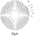
- Fig. 9 is a schematic diagram of still another example of the rotor 10 having five magnetic flux barrier layers 11 to 15.
- the first, second, third and fourth magnetic flux barrier layers 11, 12, 13 and 14 are filled with a conductor
- the fifth magnetic flux barrier layer 15 is a gap. That is, the N+1 (three) magnetic flux barrier layers from the stator side are filled with the conductor, and the entire part of the (N+2)th to 2Nth (fourth) magnetic flux barrier layer(s) is/are also filled with the conductor. From this design, both the starting torque and the efficiency of the DOL-SynRM are also taken into account.
- the conductor above may be an aluminum alloy, but the present application is not limited thereto.
- the synchronous reluctance motor may also include other constitutions. Reference may be made to related arts for details, and the description is omitted here. In addition, parts not shown in Figs. 1 to 9 may also be added, or one or more parts in Figs. 1 to 9 may be reduced. For other structures and structures of the synchronous reluctance motor, reference may be made to related technologies, and the description is omitted here.
- the magnetic flux barrier layer closest to the stator is filled with the conductor, and the magnetic flux barrier layer closest to the shaft is the gap.
- Other magnetic flux barrier layers are selected to be filled with a conductor or serve as a gap according to the required starting torque. Therefore, both the starting torque and the efficiency of the DOL-SynRM are taken into account.
- the embodiment of the second aspect of the present application provides an electrical product, which has the synchronous reluctance motor as described by the embodiments of the first aspect. Since in the embodiments of the first aspect, the structure of the synchronous reluctance motor has been described in detail, the content of which is incorporated herein, and the description is omitted here.
Landscapes
- Engineering & Computer Science (AREA)
- Power Engineering (AREA)
- Synchronous Machinery (AREA)
Abstract
Description
- Embodiments of the present application relate to the electromechanical field, in particular to a synchronous reluctance motor and an electrical product.
- A synchronous reluctance motor that can be driven directly connecting to a three-phase alternative current power source without a drive circuit is referred to as a DOL (Direct On Line) synchronous reluctance motor (SynRM). In order to drive the SynRM without the drive circuit, a conductor (an aluminum alloy) is filled in the magnetic flux barrier layers of the rotor of the SynRM.
- It should be noted that the above introduction to the Background Art is only stated for the convenience of clear and complete description of the technical solution of the present application, and to facilitate the understanding of those skilled in the art. It cannot be considered that the above technical solutions are well known to those skilled in the art just because these solutions are stated in the
- Background Art section of the present application.
- The inventor found that if a conductor is filled in a magnetic flux barrier layer, although a starting torque can be increased, the efficiency is reduced for equilibrium. For example, if the conductor is filled in the magnetic flux barrier layer, when a motor is running, additional rotor current will be generated. As a result, although the starting torque is increased, the copper loss is also increased.
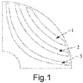
- Taking a rotor having three magnetic flux barrier layers as an example, as shown in
Fig. 1 , when all the three magnetic flux barrier layers are filled with the conductor, the copper losses corresponding to the three magnetic flux barrier layers are as shown in Table 1. It can be seen from Table 1 that the copper loss corresponding to the magneticflux barrier layer 3 closest to the shaft accounts for more than half.Table 1 Conductor position Copper loss of rotor (%) Magnetic flux barrier layer (barrier) 1 24.45 Magnetic flux barrier layer (barrier) 2 22.27 Magnetic flux barrier layer (barrier) 3 53.28 - In another aspect, when the conductor is filled in the three magnetic flux barrier layers, the starting torque of each magnetic flux barrier layer is as shown in
Fig. 2 . It can thus be seen that the starting torque of the magneticflux barrier layer 1 closest to the stator is the maximum. - In order to take both the starting torque and the efficiency of the direct on line synchronous reluctance motor (DOL-SynRM) into account, embodiments of the present application provide a synchronous reluctance motor and an electrical product.
- According to an aspect of the embodiments of the present application, a synchronous reluctance motor is provided, which has a rotor and a stator surrounding the rotor, the rotator has a rotating shaft, wherein,
- the rotator has a plurality of magnetic flux barrier layers arranged radially,
- the one of the plurality of magnetic flux barrier layers closest to the stator is filled with a conductor, and the one closest to the rotating shaft is a gap.
- According to another aspect of the embodiments of the present application, an electrical product is provided, including the aforementioned synchronous reluctance motor.
- One of the advantageous effects of the embodiments of the present application lies in that in the rotator having the plurality of magnetic flux barrier layers of the DOL-SynRM in the present application, the magnetic flux barrier layer closest to the stator is filled with the conductor, and the magnetic flux barrier layer closest to the shaft is the gap. Other magnetic flux barrier layers are selected to be filled with a conductor or serve as a gap according to the required starting torque. Therefore, both the starting torque and the efficiency of the DOL-SynRM are taken into account.
- With reference to the following description and drawings, specific implementations of the present application are disclosed in detail, indicating the ways in which the principle of the present application can be adopted. It should be understood that the scope of the implementations of the present application is not thus limited. Within the scope of the spirits and clauses of the appended claims, the implementations of the present application include many changes, modifications and equivalents.
- The included drawings are used to provide a further understanding of the embodiments of the present application, and they constitute a part of the specification, are used to illustrate the implementations of the present application, and explain the principle of the present application together with the text description. Obviously, the drawings in the following description are merely some embodiments of the present application. For those of ordinary skill in the art, other drawings can also be obtained according to these drawings without creative efforts. In the drawings:
-
Fig. 1 is a schematic diagram of a rotor structure of the existing synchronous reluctance motor. -
Fig. 2 is a schematic diagram of the starting torques corresponding to the three magnetic flux barrier layers of the rotor shown inFig. 1 . -
Fig. 3 is a schematic diagram of an example of a synchronous reluctance motor according to an embodiment of the present application. -
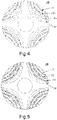
Fig. 4 is a schematic diagram of an example of a rotor having four magnetic flux barrier layers according to an embodiment of the present application. -
Fig. 5 is a schematic diagram of another example of the rotor having four magnetic flux barrier layers according to an embodiment of the present application. -
Fig. 6 is a schematic diagram of an example of a rotor having three magnetic flux barrier layers according to an embodiment of the present application. -
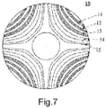
Fig. 7 is a schematic diagram of an example of a rotor having five magnetic flux barrier layers according to an embodiment of the present application. -
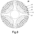
Fig. 8 is a schematic diagram of another example of the rotor having five magnetic flux barrier layers according to an embodiment of the present application. -
Fig. 9 is a schematic diagram of still another example of the rotor having five magnetic flux barrier layers according to an embodiment of the present application. - The foregoing and other features of the present application will become apparent through the following specification with reference to the drawings. In the specification and the drawings, specific implementations of the present application are specifically disclosed, indicating part of the implementations in which the principle of the present application can be adopted. It should be understood that the present application is not limited to the described implementations. On the contrary, the present application includes all modifications, variations and equivalents falling within the scope of the appended claims.
- In the embodiments of the present application, the terms "first", "second" and the like are used to distinguish different elements from names, but they do not indicate the spatial arrangement or temporal order or the like of these elements, and these elements should not be limited by these terms. The term "and/or" includes any and all combinations of one or more of the associatively listed terms. The terms "comprise", "include", "have" and the like refer to the presence of the stated features, elements, components or assemblies, but do not exclude the presence or addition of one or more other features, elements, components or assemblies.
- In the embodiments of the present application, the singular forms "a/an", "this" and the like may include plural forms, which should be broadly understood as "a kind" or "a type", rather than being limited to the meaning of "one". In addition, the term "the" should be understood as including both singular and plural forms, unless clearly stated otherwise in the context. In addition, the term "according to" should be understood as "at least in part according to...", and the term "based on" should be understood as "at least in part based on...", unless clearly stated otherwise in the context.
- In the following description of the embodiments of the present application, for the convenience of description, the direction parallel to the direction extending along the central axis O of the synchronous reluctance motor is referred to as "axial"; the radius direction centered on the central axis O is referred to as "radial"; the direction close to the central axis O is referred to as "radial inner side" or "inner side"; and the direction away from the central axis O is referred to as "radial outer side" or "outer side". It is worth noting that these are only for the convenience of description, and do not limit the orientation of the synchronous reluctance motor in use and manufacture.
- Implementations of embodiments of the present application will be illustrated below with reference to the drawings.
- Embodiments of the present application provide a synchronous reluctance motor.
-
Fig. 3 is a schematic diagram of an example of a synchronous reluctance motor according to an embodiment of the present application. As shown inFig. 3 , the synchronous reluctance motor according to the embodiment of the present application has arotor 10 and astator 20 surrounding therotor 10. In addition, the synchronous reluctance motor further includes other constitutions such as a shaft, a bearing, an enclosure and the like, which can make references to related arts. - In the embodiment of the present application, the
rotator 10 has a plurality of magnetic flux barrier layers arranged radially, the one (i.e., the magnetic flux barrier layer at the radial outmost) of the plurality of magnetic flux barrier layers closest to the stator is filled with a conductor, and the one (i.e., the magnetic flux barrier layer at the radial innermost) closest to the rotating shaft is a gap. - According to the synchronous reluctance motor (DOL-SynRM) in the embodiment of the present application, the magnetic flux barrier layer closest to the stator is filled with the conductor, and the magnetic flux barrier layer closest to the shaft is the gap. Other magnetic flux barrier layers are selected to be filled with a conductor or serve as a gap according to the required starting torque. Therefore, both the starting torque and the efficiency of the DOL-SynRM are taken into account.
- In some embodiments, the number of the magnetic flux barrier layers is 2N, N > 1, and more than N of the magnetic flux barrier layers close to the stator are filled with a conductor. In some embodiments, at least a part of the (N+1)th to (2N-1)th of the plurality of magnetic flux barrier layers closest to the stator side are filled with a conductor.
- N = 2 is taken as an example, i.e., the
rotor 10 has four magnetic flux barrier layers. -
Fig. 4 is a schematic diagram of an example of therotor 10 having four magnetic flux barrier layers 11 to 14. As shown inFig. 4 , in this example, counting from the stator side, the first and second (i.e., N) magnetic flux barrier layers 11 and 12 are filled with a conductor, a part of the third magneticflux barrier layer 13 is filled with the conductor, and the fourth magneticflux barrier layer 14 is a gap. From this design, both the starting torque and the efficiency of the DOL-SynRM are taken into account. -
Fig. 5 is a schematic diagram of another example of therotor 10 having four magnetic flux barrier layers 11 to 14. As shown inFig. 5 , in this example, counting from the stator side, the first and second (i.e., N) magnetic flux barrier layers 11 and 12 are filled with a conductor, the entire part of the third magneticflux barrier layer 13 is filled with the conductor, and the fourth magneticflux barrier layer 14 is a gap. From this design, both the starting torque and the efficiency of the DOL-SynRM are also taken into account. - In some embodiments, the number of the magnetic flux barrier layers is 2N+1, N= 1, i.e., the
rotor 10 has three magnetic flux barrier layers, and N+1 of the magnetic flux barrier layers close to the stator are filled with a conductor. -
Fig. 6 is a schematic diagram of an example of therotor 10 having three magnetic flux barrier layers 11 to 13. As shown inFig. 6 , in this example, counting from the stator side, the first and second (i.e., N+1) magnetic flux barrier layers 11 and 12 are filled with a conductor, and the third magneticflux barrier layer 13 is a gap. From this design, both the starting torque and the efficiency of the DOL-SynRM are also taken into account. - In some embodiments, the number of the magnetic flux barrier layers is 2N+1, N > 1, and more than N+1 of the magnetic flux barrier layers close to the stator are filled with a conductor. In some embodiments, at least a part of the (N+2)th to 2Nth of the plurality of magnetic flux barrier layers closet to the stator side are filled with a conductor or no conductor.
- N = 2 is taken as an example, i.e., the
rotor 10 has five magnetic flux barrier layers. -
Fig. 7 is a schematic diagram of an example of therotor 10 having five magnetic flux barrier layers 11 to 15. As shown inFig. 7 , in this example, counting from the stator side, the first, second and third (i.e., N+1) magnetic flux barrier layers 11, 12 and 13 are filled with a conductor, and the fourth and fifth magnetic flux barrier layers 14 and 15 are gaps. That is, the (N+2)th to 2Nth (fourth) magnetic flux barrier layer(s) is/are filled with no conductor. From this design, both the starting torque and the efficiency of the DOL-SynRM are also taken into account. -
Fig. 8 is a schematic diagram of another example of therotor 10 having five magnetic flux barrier layers 11 to 15. As shown inFig. 8 , in this example, counting from the stator side, the first, second and third (i.e., N+1) magnetic flux barrier layers 11, 12 and 13 are filled with a conductor, a part of the fourth (i.e., N+2 to 2N) magneticflux barrier layer 14 is filled with the conductor, and the fifth magneticflux barrier layer 15 is a gap. From this design, both the starting torque and the efficiency of the DOL-SynRM are also taken into account. -
Fig. 9 is a schematic diagram of still another example of therotor 10 having five magnetic flux barrier layers 11 to 15. As shown inFig. 9 , in this example, counting from the stator side, the first, second, third and fourth magnetic flux barrier layers 11, 12, 13 and 14 are filled with a conductor, and the fifth magneticflux barrier layer 15 is a gap. That is, the N+1 (three) magnetic flux barrier layers from the stator side are filled with the conductor, and the entire part of the (N+2)th to 2Nth (fourth) magnetic flux barrier layer(s) is/are also filled with the conductor. From this design, both the starting torque and the efficiency of the DOL-SynRM are also taken into account. - In the embodiment of the present application, the conductor above may be an aluminum alloy, but the present application is not limited thereto.
- It is worth noting that only the structure of the synchronous reluctance motor related to the present application is described above. The synchronous reluctance motor may also include other constitutions. Reference may be made to related arts for details, and the description is omitted here. In addition, parts not shown in
Figs. 1 to 9 may also be added, or one or more parts inFigs. 1 to 9 may be reduced. For other structures and structures of the synchronous reluctance motor, reference may be made to related technologies, and the description is omitted here. - According to the synchronous reluctance motor (DOL-SynRM) in the embodiment of the present application, the magnetic flux barrier layer closest to the stator is filled with the conductor, and the magnetic flux barrier layer closest to the shaft is the gap. Other magnetic flux barrier layers are selected to be filled with a conductor or serve as a gap according to the required starting torque. Therefore, both the starting torque and the efficiency of the DOL-SynRM are taken into account.
- The embodiment of the second aspect of the present application provides an electrical product, which has the synchronous reluctance motor as described by the embodiments of the first aspect. Since in the embodiments of the first aspect, the structure of the synchronous reluctance motor has been described in detail, the content of which is incorporated herein, and the description is omitted here.
- In the embodiments of the present application, for other structures of the electrical product, reference may be made to related arts, and the description is omitted here.
- The present application is described above in conjunction with specific implementations, but it should be clear to those skilled in the art that these descriptions are all exemplary, instead of limit to the protection scope of the present application. Those skilled in the art can make various variations and modifications according to the spirits and principle of the present application, which are also within the scope of the present application.
- Preferred implementations of the present application are described above with reference to the drawings. Many features and advantages of these implementations are clear according to the detailed specification, thus the appended claims are intended to cover all these features and advantages of these implementations falling within the real spirits and scope thereof. In addition, since those skilled in the art can readily conceive of many modifications and changes, the implementations of the present application are not limited to the precise structures and operations illustrated and described, but can encompass all suitable modifications and equivalents falling within their scope.
Claims (8)
- A synchronous reluctance motor having a rotor (10) and a stator (20) surrounding the rotor (10), the rotator having a rotating shaft, characterized in thatthe rotator has a plurality of magnetic flux barrier layers arranged radially,the one of the plurality of magnetic flux barrier layers closest to the stator (20) is filled with a conductor, and the one closest to the rotating shaft is a gap.
- The synchronous reluctance motor according to claim 1, characterized in that
the number of the magnetic flux barrier layers is 2N, N>1, and more than N of the magnetic flux barrier layers close to the stator (20) are filled with a conductor. - The synchronous reluctance motor according to claim 2, characterized in that
at least a part of the (N+1)th to (2N-1)th of the magnetic flux barrier layers closet to the stator side are filled with a conductor. - The synchronous reluctance motor according to claim 1, characterized in that
the number of the magnetic flux barrier layers is 2N+1, N= 1, and N+1 of the magnetic flux barrier layers close to the stator (20) are filled with a conductor. - The synchronous reluctance motor according to claim 1, characterized in that
the number of the magnetic flux barrier layers is 2N+1, N>1, and more than N+1 of the magnetic flux barrier layers close to the stator (20) are filled with a conductor. - The synchronous reluctance motor according to claim 5, characterized in that
at least a part of the (N+2)th to 2Nth of the plurality of magnetic flux barrier layers closest to the stator side are filled with a conductor or no conductor. - The synchronous reluctance motor according to any of claims 1-6, characterized in that the conductor is an aluminum alloy.
- An electrical product, characterized in that the electrical product comprises the synchronous reluctance motor according to any of claims 1 to 7.
Applications Claiming Priority (1)
| Application Number | Priority Date | Filing Date | Title |
|---|---|---|---|
| CN202011560082.7A CN114696493A (en) | 2020-12-25 | 2020-12-25 | Synchronous reluctance motor and electric product |
Publications (1)
| Publication Number | Publication Date |
|---|---|
| EP4020763A1 true EP4020763A1 (en) | 2022-06-29 |
Family
ID=79024613
Family Applications (1)
| Application Number | Title | Priority Date | Filing Date |
|---|---|---|---|
| EP21217354.6A Withdrawn EP4020763A1 (en) | 2020-12-25 | 2021-12-23 | Synchronous reluctance motor and electrical product |
Country Status (4)
| Country | Link |
|---|---|
| US (1) | US11770036B2 (en) |
| EP (1) | EP4020763A1 (en) |
| JP (1) | JP2022103103A (en) |
| CN (1) | CN114696493A (en) |
Families Citing this family (2)
| Publication number | Priority date | Publication date | Assignee | Title |
|---|---|---|---|---|
| CN219181380U (en) * | 2022-12-14 | 2023-06-13 | 日本电产株式会社 | Synchronous reluctance motor |
| CN118631005A (en) * | 2023-03-07 | 2024-09-10 | 日本电产株式会社 | Synchronous reluctance motor |
Citations (4)
| Publication number | Priority date | Publication date | Assignee | Title |
|---|---|---|---|---|
| US20030173861A1 (en) * | 2001-11-15 | 2003-09-18 | Mitsubishi Denki Kabushiki Kaisha | Rotor of a synchronous induction electric motor, and a method of producing a rotor |
| WO2018172033A1 (en) * | 2017-03-21 | 2018-09-27 | Siemens Aktiengesellschaft | Synchronous reluctance machine |
| WO2020253200A1 (en) * | 2019-06-19 | 2020-12-24 | 珠海格力电器股份有限公司 | Self-starting synchronous reluctance motor and compressor having same |
| WO2020253194A1 (en) * | 2019-06-19 | 2020-12-24 | 珠海格力电器股份有限公司 | Direct start-up and synchronous reluctance motor rotor structure and motor comprising same |
Family Cites Families (6)
| Publication number | Priority date | Publication date | Assignee | Title |
|---|---|---|---|---|
| DE102014215304A1 (en) * | 2014-08-04 | 2016-02-04 | Ksb Aktiengesellschaft | Rotor, reluctance machine and rotor manufacturing method |
| JP6588353B2 (en) * | 2016-01-28 | 2019-10-09 | 東芝産業機器システム株式会社 | Synchronous reluctance motor |
| JP7005131B2 (en) * | 2016-09-16 | 2022-02-04 | 株式会社東芝 | Rotor design method |
| JP7353786B2 (en) * | 2019-04-23 | 2023-10-02 | 東芝インフラシステムズ株式会社 | rotor of rotating electric machine |
| CN110138117B (en) * | 2019-06-19 | 2023-12-08 | 珠海格力电器股份有限公司 | Direct-starting synchronous reluctance motor rotor structure, motor and method for manufacturing rotor structure |
| JP7725250B2 (en) * | 2021-06-17 | 2025-08-19 | ニデック株式会社 | Synchronous reluctance motor |
-
2020
- 2020-12-25 CN CN202011560082.7A patent/CN114696493A/en active Pending
-
2021
- 2021-12-21 JP JP2021206579A patent/JP2022103103A/en active Pending
- 2021-12-23 EP EP21217354.6A patent/EP4020763A1/en not_active Withdrawn
- 2021-12-23 US US17/560,478 patent/US11770036B2/en active Active
Patent Citations (4)
| Publication number | Priority date | Publication date | Assignee | Title |
|---|---|---|---|---|
| US20030173861A1 (en) * | 2001-11-15 | 2003-09-18 | Mitsubishi Denki Kabushiki Kaisha | Rotor of a synchronous induction electric motor, and a method of producing a rotor |
| WO2018172033A1 (en) * | 2017-03-21 | 2018-09-27 | Siemens Aktiengesellschaft | Synchronous reluctance machine |
| WO2020253200A1 (en) * | 2019-06-19 | 2020-12-24 | 珠海格力电器股份有限公司 | Self-starting synchronous reluctance motor and compressor having same |
| WO2020253194A1 (en) * | 2019-06-19 | 2020-12-24 | 珠海格力电器股份有限公司 | Direct start-up and synchronous reluctance motor rotor structure and motor comprising same |
Non-Patent Citations (2)
| Title |
|---|
| GANESAN ASWIN UVARAJ ET AL: "Review on the evolution of technology advancements and applications of line-start synchronous machines", IET ELECTRIC POWER APPLICATIONS, IET, UK, vol. 13, no. 1, 1 January 2019 (2019-01-01), pages 1 - 16, XP006079504, ISSN: 1751-8660, DOI: 10.1049/IET-EPA.2018.5283 * |
| HU YUSHENG ET AL: "Rotor Design and Optimization of the Three-phase Line-start Synchronous Reluctance Motor", 2019 22ND INTERNATIONAL CONFERENCE ON ELECTRICAL MACHINES AND SYSTEMS (ICEMS), IEEE, 11 August 2019 (2019-08-11), pages 1 - 6, XP033643727, DOI: 10.1109/ICEMS.2019.8922128 * |
Also Published As
| Publication number | Publication date |
|---|---|
| US20220209595A1 (en) | 2022-06-30 |
| JP2022103103A (en) | 2022-07-07 |
| US11770036B2 (en) | 2023-09-26 |
| CN114696493A (en) | 2022-07-01 |
Similar Documents
| Publication | Publication Date | Title |
|---|---|---|
| US20210367484A1 (en) | High acceleration rotary actuator | |
| US7030528B2 (en) | Dual concentric AC motor | |
| US4568846A (en) | Permanent magnet laminated rotor with conductor bars | |
| US20060192453A1 (en) | Modular transverse flux motor with integrated brake | |
| US8264120B2 (en) | Permanent-magnet-less synchronous reluctance system | |
| EP2506400B1 (en) | Permanent magnet retainers on a rotor | |
| JP2004032984A (en) | Induction motor | |
| JP6868690B2 (en) | Rotating actuator | |
| JP2011504089A (en) | Generator / induction motor with concentric multi-stage rotors | |
| US11770036B2 (en) | Synchronous reluctance motor and electrical product | |
| US11043885B2 (en) | Rotary actuator | |
| US9171692B2 (en) | Drive for rotary anode with stator with yoke winding | |
| JP2011024417A (en) | Motor | |
| US20210211001A1 (en) | Rotor and motor having rotor | |
| JP5409380B2 (en) | Electric machine | |
| US11114913B2 (en) | Rotating electric machine | |
| EP3852243A1 (en) | Motor, and coil used for same | |
| JP4482918B2 (en) | Permanent magnet type electric motor having ring-shaped stator coil | |
| US20210021181A1 (en) | Multi-rotor electrical machine with radial configuration | |
| CN114421658B (en) | Axially staggered permanent magnet motor | |
| JP2005253280A (en) | Outer rotor type brushless dc motor and ac servo motor having annular stator coil | |
| CN116231893B (en) | Permanent magnet synchronous motor with notch on stator and direct-drive driving system | |
| CN201286052Y (en) | Novel transverse magnetic flux permanent magnet motor | |
| KR20050030068A (en) | A flat board type brushless dc motor | |
| JP2007166798A (en) | Rotating electric machine, compressor, blower, and air conditioner |
Legal Events
| Date | Code | Title | Description |
|---|---|---|---|
| PUAI | Public reference made under article 153(3) epc to a published international application that has entered the european phase |
Free format text: ORIGINAL CODE: 0009012 |
|
| STAA | Information on the status of an ep patent application or granted ep patent |
Free format text: STATUS: THE APPLICATION HAS BEEN PUBLISHED |
|
| AK | Designated contracting states |
Kind code of ref document: A1 Designated state(s): AL AT BE BG CH CY CZ DE DK EE ES FI FR GB GR HR HU IE IS IT LI LT LU LV MC MK MT NL NO PL PT RO RS SE SI SK SM TR |
|
| RIN1 | Information on inventor provided before grant (corrected) |
Inventor name: LIU, CHENG-TSUNG Inventor name: YAN, GUO-JHIH Inventor name: LIN, HSIN-NAN Inventor name: LUO, TA-YIN Inventor name: YEN, SHENG-CHAN Inventor name: HSU, YU-WEI Inventor name: SHIH, PEI-CHUN |
|
| STAA | Information on the status of an ep patent application or granted ep patent |
Free format text: STATUS: THE APPLICATION IS DEEMED TO BE WITHDRAWN |
|
| 18D | Application deemed to be withdrawn |
Effective date: 20230103 |