EP4020753B1 - Backup battery control module and backup battery control system - Google Patents
Backup battery control module and backup battery control system Download PDFInfo
- Publication number
- EP4020753B1 EP4020753B1 EP21214027.1A EP21214027A EP4020753B1 EP 4020753 B1 EP4020753 B1 EP 4020753B1 EP 21214027 A EP21214027 A EP 21214027A EP 4020753 B1 EP4020753 B1 EP 4020753B1
- Authority
- EP
- European Patent Office
- Prior art keywords
- backup battery
- battery
- charging rate
- deterioration degree
- rate
- Prior art date
- Legal status (The legal status is an assumption and is not a legal conclusion. Google has not performed a legal analysis and makes no representation as to the accuracy of the status listed.)
- Active
Links
Images


Classifications
-
- H—ELECTRICITY
- H02—GENERATION; CONVERSION OR DISTRIBUTION OF ELECTRIC POWER
- H02J—ELECTRIC POWER NETWORKS; CIRCUIT ARRANGEMENTS OR SYSTEMS FOR SUPPLYING OR DISTRIBUTING ELECTRIC POWER; SYSTEMS FOR STORING ELECTRIC ENERGY
- H02J7/00—Circuit arrangements for charging or discharging batteries or for supplying loads from batteries
- H02J7/90—Regulation of charging or discharging current or voltage
- H02J7/933—Regulation of charging or discharging current or voltage the cycle being controlled or terminated in response to electric parameters
-
- H—ELECTRICITY
- H02—GENERATION; CONVERSION OR DISTRIBUTION OF ELECTRIC POWER
- H02J—ELECTRIC POWER NETWORKS; CIRCUIT ARRANGEMENTS OR SYSTEMS FOR SUPPLYING OR DISTRIBUTING ELECTRIC POWER; SYSTEMS FOR STORING ELECTRIC ENERGY
- H02J9/00—Circuit arrangements for emergency or stand-by power supply, e.g. for emergency lighting
- H02J9/04—Circuit arrangements for emergency or stand-by power supply, e.g. for emergency lighting in which the distribution system is disconnected from the normal source and connected to a standby source
- H02J9/06—Circuit arrangements for emergency or stand-by power supply, e.g. for emergency lighting in which the distribution system is disconnected from the normal source and connected to a standby source with automatic change-over, e.g. UPS systems
- H02J9/061—Circuit arrangements for emergency or stand-by power supply, e.g. for emergency lighting in which the distribution system is disconnected from the normal source and connected to a standby source with automatic change-over, e.g. UPS systems for DC powered loads
-
- B—PERFORMING OPERATIONS; TRANSPORTING
- B60—VEHICLES IN GENERAL
- B60L—PROPULSION OF ELECTRICALLY-PROPELLED VEHICLES; SUPPLYING ELECTRIC POWER FOR AUXILIARY EQUIPMENT OF ELECTRICALLY-PROPELLED VEHICLES; ELECTRODYNAMIC BRAKE SYSTEMS FOR VEHICLES IN GENERAL; MAGNETIC SUSPENSION OR LEVITATION FOR VEHICLES; MONITORING OPERATING VARIABLES OF ELECTRICALLY-PROPELLED VEHICLES; ELECTRIC SAFETY DEVICES FOR ELECTRICALLY-PROPELLED VEHICLES
- B60L58/00—Methods or circuit arrangements for monitoring or controlling batteries or fuel cells, specially adapted for electric vehicles
- B60L58/10—Methods or circuit arrangements for monitoring or controlling batteries or fuel cells, specially adapted for electric vehicles for monitoring or controlling batteries
-
- B—PERFORMING OPERATIONS; TRANSPORTING
- B60—VEHICLES IN GENERAL
- B60L—PROPULSION OF ELECTRICALLY-PROPELLED VEHICLES; SUPPLYING ELECTRIC POWER FOR AUXILIARY EQUIPMENT OF ELECTRICALLY-PROPELLED VEHICLES; ELECTRODYNAMIC BRAKE SYSTEMS FOR VEHICLES IN GENERAL; MAGNETIC SUSPENSION OR LEVITATION FOR VEHICLES; MONITORING OPERATING VARIABLES OF ELECTRICALLY-PROPELLED VEHICLES; ELECTRIC SAFETY DEVICES FOR ELECTRICALLY-PROPELLED VEHICLES
- B60L58/00—Methods or circuit arrangements for monitoring or controlling batteries or fuel cells, specially adapted for electric vehicles
- B60L58/10—Methods or circuit arrangements for monitoring or controlling batteries or fuel cells, specially adapted for electric vehicles for monitoring or controlling batteries
- B60L58/12—Methods or circuit arrangements for monitoring or controlling batteries or fuel cells, specially adapted for electric vehicles for monitoring or controlling batteries responding to state of charge [SoC]
- B60L58/13—Maintaining the SoC within a determined range
-
- B—PERFORMING OPERATIONS; TRANSPORTING
- B60—VEHICLES IN GENERAL
- B60L—PROPULSION OF ELECTRICALLY-PROPELLED VEHICLES; SUPPLYING ELECTRIC POWER FOR AUXILIARY EQUIPMENT OF ELECTRICALLY-PROPELLED VEHICLES; ELECTRODYNAMIC BRAKE SYSTEMS FOR VEHICLES IN GENERAL; MAGNETIC SUSPENSION OR LEVITATION FOR VEHICLES; MONITORING OPERATING VARIABLES OF ELECTRICALLY-PROPELLED VEHICLES; ELECTRIC SAFETY DEVICES FOR ELECTRICALLY-PROPELLED VEHICLES
- B60L58/00—Methods or circuit arrangements for monitoring or controlling batteries or fuel cells, specially adapted for electric vehicles
- B60L58/10—Methods or circuit arrangements for monitoring or controlling batteries or fuel cells, specially adapted for electric vehicles for monitoring or controlling batteries
- B60L58/16—Methods or circuit arrangements for monitoring or controlling batteries or fuel cells, specially adapted for electric vehicles for monitoring or controlling batteries responding to battery ageing, e.g. to the number of charging cycles or the state of health [SoH]
-
- B—PERFORMING OPERATIONS; TRANSPORTING
- B60—VEHICLES IN GENERAL
- B60L—PROPULSION OF ELECTRICALLY-PROPELLED VEHICLES; SUPPLYING ELECTRIC POWER FOR AUXILIARY EQUIPMENT OF ELECTRICALLY-PROPELLED VEHICLES; ELECTRODYNAMIC BRAKE SYSTEMS FOR VEHICLES IN GENERAL; MAGNETIC SUSPENSION OR LEVITATION FOR VEHICLES; MONITORING OPERATING VARIABLES OF ELECTRICALLY-PROPELLED VEHICLES; ELECTRIC SAFETY DEVICES FOR ELECTRICALLY-PROPELLED VEHICLES
- B60L58/00—Methods or circuit arrangements for monitoring or controlling batteries or fuel cells, specially adapted for electric vehicles
- B60L58/10—Methods or circuit arrangements for monitoring or controlling batteries or fuel cells, specially adapted for electric vehicles for monitoring or controlling batteries
- B60L58/18—Methods or circuit arrangements for monitoring or controlling batteries or fuel cells, specially adapted for electric vehicles for monitoring or controlling batteries of two or more battery modules
-
- B—PERFORMING OPERATIONS; TRANSPORTING
- B60—VEHICLES IN GENERAL
- B60L—PROPULSION OF ELECTRICALLY-PROPELLED VEHICLES; SUPPLYING ELECTRIC POWER FOR AUXILIARY EQUIPMENT OF ELECTRICALLY-PROPELLED VEHICLES; ELECTRODYNAMIC BRAKE SYSTEMS FOR VEHICLES IN GENERAL; MAGNETIC SUSPENSION OR LEVITATION FOR VEHICLES; MONITORING OPERATING VARIABLES OF ELECTRICALLY-PROPELLED VEHICLES; ELECTRIC SAFETY DEVICES FOR ELECTRICALLY-PROPELLED VEHICLES
- B60L58/00—Methods or circuit arrangements for monitoring or controlling batteries or fuel cells, specially adapted for electric vehicles
- B60L58/10—Methods or circuit arrangements for monitoring or controlling batteries or fuel cells, specially adapted for electric vehicles for monitoring or controlling batteries
- B60L58/18—Methods or circuit arrangements for monitoring or controlling batteries or fuel cells, specially adapted for electric vehicles for monitoring or controlling batteries of two or more battery modules
- B60L58/21—Methods or circuit arrangements for monitoring or controlling batteries or fuel cells, specially adapted for electric vehicles for monitoring or controlling batteries of two or more battery modules having the same nominal voltage
-
- G—PHYSICS
- G01—MEASURING; TESTING
- G01K—MEASURING TEMPERATURE; MEASURING QUANTITY OF HEAT; THERMALLY-SENSITIVE ELEMENTS NOT OTHERWISE PROVIDED FOR
- G01K13/00—Thermometers specially adapted for specific purposes
-
- G—PHYSICS
- G01—MEASURING; TESTING
- G01R—MEASURING ELECTRIC VARIABLES; MEASURING MAGNETIC VARIABLES
- G01R31/00—Arrangements for testing electric properties; Arrangements for locating electric faults; Arrangements for electrical testing characterised by what is being tested not provided for elsewhere
- G01R31/36—Arrangements for testing, measuring or monitoring the electrical condition of accumulators or electric batteries, e.g. capacity or state of charge [SoC]
- G01R31/382—Arrangements for monitoring battery or accumulator variables, e.g. SoC
- G01R31/3835—Arrangements for monitoring battery or accumulator variables, e.g. SoC involving only voltage measurements
-
- G—PHYSICS
- G01—MEASURING; TESTING
- G01R—MEASURING ELECTRIC VARIABLES; MEASURING MAGNETIC VARIABLES
- G01R31/00—Arrangements for testing electric properties; Arrangements for locating electric faults; Arrangements for electrical testing characterised by what is being tested not provided for elsewhere
- G01R31/36—Arrangements for testing, measuring or monitoring the electrical condition of accumulators or electric batteries, e.g. capacity or state of charge [SoC]
- G01R31/382—Arrangements for monitoring battery or accumulator variables, e.g. SoC
- G01R31/3842—Arrangements for monitoring battery or accumulator variables, e.g. SoC combining voltage and current measurements
-
- G—PHYSICS
- G01—MEASURING; TESTING
- G01R—MEASURING ELECTRIC VARIABLES; MEASURING MAGNETIC VARIABLES
- G01R31/00—Arrangements for testing electric properties; Arrangements for locating electric faults; Arrangements for electrical testing characterised by what is being tested not provided for elsewhere
- G01R31/36—Arrangements for testing, measuring or monitoring the electrical condition of accumulators or electric batteries, e.g. capacity or state of charge [SoC]
- G01R31/389—Measuring internal impedance, internal conductance or related variables
-
- G—PHYSICS
- G01—MEASURING; TESTING
- G01R—MEASURING ELECTRIC VARIABLES; MEASURING MAGNETIC VARIABLES
- G01R31/00—Arrangements for testing electric properties; Arrangements for locating electric faults; Arrangements for electrical testing characterised by what is being tested not provided for elsewhere
- G01R31/36—Arrangements for testing, measuring or monitoring the electrical condition of accumulators or electric batteries, e.g. capacity or state of charge [SoC]
- G01R31/392—Determining battery ageing or deterioration, e.g. state of health
-
- H—ELECTRICITY
- H02—GENERATION; CONVERSION OR DISTRIBUTION OF ELECTRIC POWER
- H02J—ELECTRIC POWER NETWORKS; CIRCUIT ARRANGEMENTS OR SYSTEMS FOR SUPPLYING OR DISTRIBUTING ELECTRIC POWER; SYSTEMS FOR STORING ELECTRIC ENERGY
- H02J7/00—Circuit arrangements for charging or discharging batteries or for supplying loads from batteries
- H02J7/34—Parallel operation in networks using both storage and other DC sources, e.g. providing buffering
- H02J7/342—The other DC source being a battery actively interacting with the first one, i.e. battery to battery charging
-
- H—ELECTRICITY
- H02—GENERATION; CONVERSION OR DISTRIBUTION OF ELECTRIC POWER
- H02J—ELECTRIC POWER NETWORKS; CIRCUIT ARRANGEMENTS OR SYSTEMS FOR SUPPLYING OR DISTRIBUTING ELECTRIC POWER; SYSTEMS FOR STORING ELECTRIC ENERGY
- H02J7/00—Circuit arrangements for charging or discharging batteries or for supplying loads from batteries
- H02J7/80—Circuit arrangements for charging or discharging batteries or for supplying loads from batteries including monitoring or indicating arrangements
- H02J7/82—Control of state of charge [SOC]
-
- H—ELECTRICITY
- H02—GENERATION; CONVERSION OR DISTRIBUTION OF ELECTRIC POWER
- H02J—ELECTRIC POWER NETWORKS; CIRCUIT ARRANGEMENTS OR SYSTEMS FOR SUPPLYING OR DISTRIBUTING ELECTRIC POWER; SYSTEMS FOR STORING ELECTRIC ENERGY
- H02J7/00—Circuit arrangements for charging or discharging batteries or for supplying loads from batteries
- H02J7/80—Circuit arrangements for charging or discharging batteries or for supplying loads from batteries including monitoring or indicating arrangements
- H02J7/84—Control of state of health [SOH]
-
- H—ELECTRICITY
- H02—GENERATION; CONVERSION OR DISTRIBUTION OF ELECTRIC POWER
- H02J—ELECTRIC POWER NETWORKS; CIRCUIT ARRANGEMENTS OR SYSTEMS FOR SUPPLYING OR DISTRIBUTING ELECTRIC POWER; SYSTEMS FOR STORING ELECTRIC ENERGY
- H02J7/00—Circuit arrangements for charging or discharging batteries or for supplying loads from batteries
- H02J7/855—Circuit arrangements for charging or discharging batteries or for supplying loads from batteries with circuits adapted for supplying loads from the battery
-
- H—ELECTRICITY
- H02—GENERATION; CONVERSION OR DISTRIBUTION OF ELECTRIC POWER
- H02J—ELECTRIC POWER NETWORKS; CIRCUIT ARRANGEMENTS OR SYSTEMS FOR SUPPLYING OR DISTRIBUTING ELECTRIC POWER; SYSTEMS FOR STORING ELECTRIC ENERGY
- H02J9/00—Circuit arrangements for emergency or stand-by power supply, e.g. for emergency lighting
- H02J9/04—Circuit arrangements for emergency or stand-by power supply, e.g. for emergency lighting in which the distribution system is disconnected from the normal source and connected to a standby source
-
- B—PERFORMING OPERATIONS; TRANSPORTING
- B60—VEHICLES IN GENERAL
- B60L—PROPULSION OF ELECTRICALLY-PROPELLED VEHICLES; SUPPLYING ELECTRIC POWER FOR AUXILIARY EQUIPMENT OF ELECTRICALLY-PROPELLED VEHICLES; ELECTRODYNAMIC BRAKE SYSTEMS FOR VEHICLES IN GENERAL; MAGNETIC SUSPENSION OR LEVITATION FOR VEHICLES; MONITORING OPERATING VARIABLES OF ELECTRICALLY-PROPELLED VEHICLES; ELECTRIC SAFETY DEVICES FOR ELECTRICALLY-PROPELLED VEHICLES
- B60L2240/00—Control parameters of input or output; Target parameters
- B60L2240/40—Drive Train control parameters
- B60L2240/54—Drive Train control parameters related to batteries
- B60L2240/545—Temperature
-
- B—PERFORMING OPERATIONS; TRANSPORTING
- B60—VEHICLES IN GENERAL
- B60L—PROPULSION OF ELECTRICALLY-PROPELLED VEHICLES; SUPPLYING ELECTRIC POWER FOR AUXILIARY EQUIPMENT OF ELECTRICALLY-PROPELLED VEHICLES; ELECTRODYNAMIC BRAKE SYSTEMS FOR VEHICLES IN GENERAL; MAGNETIC SUSPENSION OR LEVITATION FOR VEHICLES; MONITORING OPERATING VARIABLES OF ELECTRICALLY-PROPELLED VEHICLES; ELECTRIC SAFETY DEVICES FOR ELECTRICALLY-PROPELLED VEHICLES
- B60L2240/00—Control parameters of input or output; Target parameters
- B60L2240/40—Drive Train control parameters
- B60L2240/54—Drive Train control parameters related to batteries
- B60L2240/547—Voltage
-
- B—PERFORMING OPERATIONS; TRANSPORTING
- B60—VEHICLES IN GENERAL
- B60L—PROPULSION OF ELECTRICALLY-PROPELLED VEHICLES; SUPPLYING ELECTRIC POWER FOR AUXILIARY EQUIPMENT OF ELECTRICALLY-PROPELLED VEHICLES; ELECTRODYNAMIC BRAKE SYSTEMS FOR VEHICLES IN GENERAL; MAGNETIC SUSPENSION OR LEVITATION FOR VEHICLES; MONITORING OPERATING VARIABLES OF ELECTRICALLY-PROPELLED VEHICLES; ELECTRIC SAFETY DEVICES FOR ELECTRICALLY-PROPELLED VEHICLES
- B60L2250/00—Driver interactions
-
- H—ELECTRICITY
- H02—GENERATION; CONVERSION OR DISTRIBUTION OF ELECTRIC POWER
- H02J—ELECTRIC POWER NETWORKS; CIRCUIT ARRANGEMENTS OR SYSTEMS FOR SUPPLYING OR DISTRIBUTING ELECTRIC POWER; SYSTEMS FOR STORING ELECTRIC ENERGY
- H02J2105/00—Networks for supplying or distributing electric power characterised by their spatial reach or by the load
- H02J2105/30—Networks for supplying or distributing electric power characterised by their spatial reach or by the load the load networks being external to vehicles, i.e. exchanging power with vehicles
- H02J2105/33—Networks for supplying or distributing electric power characterised by their spatial reach or by the load the load networks being external to vehicles, i.e. exchanging power with vehicles exchanging power with road vehicles
-
- H—ELECTRICITY
- H02—GENERATION; CONVERSION OR DISTRIBUTION OF ELECTRIC POWER
- H02J—ELECTRIC POWER NETWORKS; CIRCUIT ARRANGEMENTS OR SYSTEMS FOR SUPPLYING OR DISTRIBUTING ELECTRIC POWER; SYSTEMS FOR STORING ELECTRIC ENERGY
- H02J2105/00—Networks for supplying or distributing electric power characterised by their spatial reach or by the load
- H02J2105/30—Networks for supplying or distributing electric power characterised by their spatial reach or by the load the load networks being external to vehicles, i.e. exchanging power with vehicles
- H02J2105/33—Networks for supplying or distributing electric power characterised by their spatial reach or by the load the load networks being external to vehicles, i.e. exchanging power with vehicles exchanging power with road vehicles
- H02J2105/37—Networks for supplying or distributing electric power characterised by their spatial reach or by the load the load networks being external to vehicles, i.e. exchanging power with vehicles exchanging power with road vehicles exchanging power with electric vehicles [EV] or with hybrid electric vehicles [HEV]
Definitions
- Patent Literature 1 JP-A-2017-116336 WO 2018/180333 A1 discloses an in-vehicle power supply system control device that detects whether a power storage unit is in a deteriorated state, based on the resistance and the capacitance of the power storage unit. If yes, the power storage unit is charged to a target voltage that is higher than the target voltage used when the power supply unit is not in a deteriorated state.
- an object of the present disclosure is to provide a backup battery control module and a backup battery control system capable of reducing occurrence of a situation, in which a backup battery does not secure a required remaining capacity required to continue driving of a load for causing a vehicle to travel when electric power supply by a main battery is cut off and the driving of the load for causing the vehicle to travel is to be continued, as compared with the related art.
- the present disclosure provides a backup battery control module configured to supply electric power from a main battery to a load required for causing a vehicle to travel and supply electric power from a backup battery to the load when electric power supply from the main battery to the load is cut off, the backup battery control module including: an open circuit voltage measurement unit configured to measure an open circuit voltage of the backup battery every first predetermined time in a state in which an ignition switch is off, to obtain a measured open circuit voltage; an already charged rate derivation unit configured to derive, based on the measured open circuit voltage, an already charged rate of the backup battery that has already been charged; an internal resistance measurement unit configured to measure an internal resistance of the backup battery at every second predetermined time in a state in which the ignition switch is off, to obtain a measured internal resistance; a deterioration degree derivation unit configured to derive a deterioration degree of the backup battery based on the measured internal resistance; a target charging rate derivation unit configured to derive a target charging rate serving as a charging target based on the deterioration degree
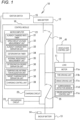
- Fig. 1 is a block diagram of a control system 10 including a control module 16 according to an embodiment of the present disclosure.
- the control system 10 and the control module 16 are used in a self-driving vehicle (not shown).
- the self-driving vehicle means, for example, a vehicle that can autonomously travel without a person performing a driving operation.
- the self-driving vehicle autonomously travels only by recognizing the surrounding environment with a radar, a GPS, a camera, and the like and designating a destination. It is assumed that the self-driving vehicle of the present embodiment is capable of being autonomously driven by a driver on the vehicle, and is capable of being manually driven by the driver by switching to manual driving.
- the control system 10 is an example of a backup battery control system
- the control module 16 is an example of a backup battery control module.
- the control system 10 (backup battery control system) includes a load 11, a main battery 12, a backup battery 13, a battery temperature sensor 14, an ignition switch 15, and a control module 16 (backup battery control module).
- the load 11, the main battery 12, the backup battery 13, the battery temperature sensor 14, and the ignition switch 15 are mounted in a vehicle (not shown) of a self-driving vehicle (not shown) in advance, and the control module 16 according to the present embodiment can be retrofitted to such a configuration.
- a vehicle-side control unit 41 is also shown in Fig. 1 , the vehicle-side control unit 41 is mounted on the vehicle of the self-driving vehicle in advance, and is connected to the load 11 and the like to control driving of the load 11 and the like.
- the control module 16 supplies the electric power from the main battery 12 to the load 11 required to cause the vehicle to travel, and supplies the electric power from the backup battery 13 to the load 11 when the electric power supply from the main battery 12 to the load 11 is cut off.
- the control module 16 includes a microcomputer 21, a charging circuit 22, a discharging circuit 23, and switches 24 and 25. As described above, the control module 16 is retrofitted (in an add-on form) to the vehicle of the self-driving vehicle. Therefore, the microcomputer 21 is provided separately from the vehicle-side control unit 41 that controls the driving of the vehicle. The microcomputer 21 controls driving of the charging circuit 22, the discharging circuit 23, and the switches 24 and 25.
- the charging circuit 22 is a circuit for charging the backup battery 13 with electricity of the main battery 12.
- the discharging circuit 23 functions as a dedicated constant current discharge system and is a circuit for discharging electricity held by the backup battery 13. An internal resistance of the backup battery 13 can be measured by a voltage drop of the backup battery 13 due to the discharge.
- the microcomputer 21 includes an already charged rate timer 31, an open circuit voltage measurement unit 32, an already charged rate derivation unit 33, a deterioration timer 34, an internal resistance measurement unit 35, a deterioration degree derivation unit 36, a temperature information acquisition unit 37, a target charging rate derivation unit 38, and a charging control unit 39.
- the microcomputer 21 may include a processor and a memory storing instructions that, when executed by the processor, cause the microcomputer 21 to perform operations by at least one of the elements 31 to 39.
- the already charged rate timer 31 measures a first predetermined time (for example, half a day). Based on the measurement result, the microcomputer 21 drives the open circuit voltage measurement unit 32 and the already charged rate derivation unit 33 every first predetermined time (for example, every half day).
- the open circuit voltage measurement unit 32 measures the open circuit voltage. This is because it is difficult for the open circuit voltage measurement unit 32 to accurately measure the open circuit voltage when the ignition switch 15 is on (for example, when the vehicle is traveling).
- the deterioration degree derivation unit 36 derives the deterioration degree of the backup battery 13 based on the voltage drop amount and the discharge current of the internal resistance measurement unit 35. Hereinafter, the content will be described in detail.
- Fig. 2B is a graph showing a relationship between a battery voltage and a discharging time of the backup battery 13 when the discharging time is short.
- the vertical axis represents the battery voltage of the backup battery 13
- the horizontal axis represents the discharging time of the backup battery 13.
- a graph J1 is a graph (0% deterioration) of a new backup battery 13
- a graph J2 is a graph (for example, 20% deterioration) of a current (used) backup battery 13 after a predetermined period has elapsed from the start of use.
- These graphs J1 and J2 mainly show a drop amount of the battery voltage when a discharge current 10 A is discharged for a discharging time of about 10 seconds in the new backup battery 13 and the current backup battery 13.
- the internal resistance based on the voltage drop amount of the deteriorated battery is calculated to be large, the internal resistance based on the voltage drop amount of the new battery is calculated to be small, and the degree of increase in the internal resistance of the deteriorated battery compared to the internal resistance of the new battery is derived as the deterioration degree of the current battery.
- the internal resistance measurement unit 35 receives data of the battery voltage and the discharging time of the graph J1 of Fig. 2B .
- the battery voltage before the discharge is Y1 [mV]
- the battery voltage after the discharge is Y11 [mV]
- the voltage drop amount is V1 [mV].
- the internal resistance measurement unit 35 receives data of the battery voltage and the discharging time of the graph J2 of Fig. 2B .
- the battery voltage before the discharge is Y2 [mV]
- the battery voltage after the discharge is Y21 [mV]
- the voltage drop amount is V2 [mV].
- the internal resistance measurement unit 35 derives the deterioration degree from the viewpoint of an amount of the internal resistance of the current backup battery 13 increases with respect to the internal resistance of the backup battery 13 at the time of new battery.
- the temperature information acquisition unit 37 acquires temperature information of the backup battery 13 from the battery temperature sensor 14. This is because the temperature also affects a charging rate of the backup battery 13.
- the target charging rate derivation unit 38 acquires a target charging rate serving as a charging target based on a derivation result by the deterioration degree derivation unit 36 and the temperature information acquired by the temperature information acquisition unit 37 such that a required remaining capacity required for the load 11 is secured in the backup battery 13 when the electric power supply from the main battery 12 to the load 11 is cut off.
- the target charging rates are a1 to a7 [%], b1 to b7 [%], c1 to c7 [%], and d1 to d7 [%] in Fig. 2E described later.
- the target charging rate is the remaining capacity of the backup battery 13 required to continue the driving of the load for causing the self-driving vehicle to travel with respect to the remaining capacity of the backup battery 13 having a charging rate of 100%.
- a relationship between the target charging rate and the deterioration degree and a relationship between the target charging rate and the battery temperature are theoretically considered as follows.
- the remaining capacity of the new backup battery 13 having the charging rate of 100% is 30000 [Asec]
- the remaining capacity of the current backup battery 13 having the charging rate of 100% is 24000 [Asec]
- the required remaining capacity required to continue the driving of the load for causing the self-driving vehicle to travel is a remaining capacity for flowing a current of 80 A for 3 minutes.
- the target charging rate derivation unit 38 needs to calculate the target charging rate to be larger as the temperature of the backup battery 13 decreases (see Fig. 2E and Fig. 2C ).
- Fig. 2C is a graph showing the relationship between the target charging rate and the battery temperature of the backup battery 13.
- the vertical axis represents the target charging rate of the backup battery 13
- the horizontal axis represents the battery temperature of the backup battery 13.
- An appropriate temperature of the backup battery 13 is - 40°C to 60°C. Within a range of such the appropriate temperature, the backup battery 13 has a property in which a battery capacity increases as the battery temperature increases and the battery capacity decreases as the battery temperature decreases. Therefore, as shown in Fig. 2C , the higher the battery temperature is, the smaller the target charging rate is, and the lower the battery temperature is, the larger the target charging rate is required.
- Fig. 2E is a table showing the target charging rate based on the deterioration degree and the battery temperature of the backup battery 13.
- Rows are classified by setting the battery temperature to - 40°C to 60°C, and for example, when the deterioration degree is 20%, as the battery temperature sequentially decreases from 60 °C to - 40°C, the target charging rate sequentially increases from d1 to d7 (d7 > d6 > d5 > d4 > d3 > d2 > d1).
- the deterioration degree is another numerical value, the deterioration degree is set in the same manner.
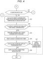
- FIGS. 3 and 4 are flowcharts showing a control process of the microcomputer 21. Since there is a plurality of units inside the microcomputer 21 as shown in Fig. 1 , the following description will be made by specifying the subject of control as much as possible.
- the microcomputer 21 determines whether the ignition switch 15 is on (step 1, hereinafter "step” is indicated as “S"; S1). When it is determined in S1 that the ignition switch 15 is on (S1: YES), the process proceeds to A of Fig. 4 . When it is determined in S1 that the ignition switch 15 is not on (S1: NO), the microcomputer 21 determines whether there is no communication from a host device (not shown) for a predetermined time (S2). When it is determined in S2 that there has been the communication performed within the predetermined time (S2: YES), the process proceeds to S4.
- the process proceeds to a sleep state in which a timer other than the already charged rate timer 31 and the deterioration timer 34 is not activated (S3).
- the microcomputer 21 determines whether a first predetermined period has elapsed from start of the already charged rate timer 31 (S4).
- the microcomputer 21 When it is determined in S4 that the first predetermined period has elapsed from start of the already charged rate timer 31 (S4: YES), the microcomputer 21 resets the already charged rate timer 31 (S5). At this time, components other than the already charged rate timer 31 and the deterioration timer 34, which have been in the sleep state, are activated.
- the control process is ended.
- the charging control unit 39 charges the backup battery 13 until the already charged rate reaches the target charging rate (S24).
- the microcomputer 21 resets the already charged rate timer 31 (S25). Thereafter, the microcomputer 21 determines whether electric power can be supplied from the main battery 12 to the load 11 (S26).
- control module 16 of the present embodiment includes the open circuit voltage measurement unit 32, the already charged rate derivation unit 33, the internal resistance measurement unit 35, the deterioration degree derivation unit 36, the target charging rate derivation unit 38 that derives the target charging rate serving as the charging target based on the deterioration degree derived by the deterioration degree derivation unit 36 such that a required remaining capacity required for the load 11 is secured in the backup battery 13 when the electric power supply from the main battery 12 to the load 11 is cut off, and the charging control unit 39 that charges the backup battery 13 until the target charging rate is reached when it is determined that the already charged rate is smaller than the target charging rate based on the deterioration degree.
- the target charging rate can be derived more accurately. Further, it is also more accurately determined that the already charged rate is smaller than the target charging rate. Further, it is possible to more reliably secure the required remaining capacity required to continue the driving of the load for causing the vehicle to travel. As a result, it is possible to reduce occurrence of a situation, in which the backup battery 13 does not secure the required remaining capacity required to continue driving of the load for causing the vehicle to travel when the electric power supply by the main battery 12 is cut off and the driving of the load for causing the vehicle to travel is to be continued, as compared with the related art.
- the target charging rate derivation unit 38 acquires the target charging rate, and the charging control unit 39 charges the backup battery 13 based on the target charging rate derived by the target charging rate derivation unit 38. According to such a configuration, when the ignition switch 15 is off, a decrease in the capacity of the main battery 12 is prevented as compared with the case where the same operation is performed.
- control module 16 further includes the temperature information acquisition unit 37.
- the target charging rate derivation unit 38 acquires the target charging rate serving as the charging target based on the temperature information acquired by the temperature information acquisition unit 37 in addition to the deterioration degree derived by the deterioration degree derivation unit 36. According to such a configuration, it is possible to acquire a more suitable value as the target charging rate by taking into account the temperature information.
- the microcomputer 21 is provided separately from the vehicle-side control unit 41 that controls the driving of the vehicle. According to such a configuration, if the vehicle-side control unit 41 performs charging control, it is necessary to construct a system for each vehicle type, whereas the microcomputer 21 performs the charging control separately from the vehicle-side control unit 41, and thus it is not necessary to construct a system for each vehicle type. Further, it is possible to avoid an increase in a load on the vehicle-side control unit 41 for charging the backup battery 13.
Landscapes
- Engineering & Computer Science (AREA)
- Power Engineering (AREA)
- General Physics & Mathematics (AREA)
- Sustainable Development (AREA)
- Sustainable Energy (AREA)
- Transportation (AREA)
- Mechanical Engineering (AREA)
- Physics & Mathematics (AREA)
- Life Sciences & Earth Sciences (AREA)
- Business, Economics & Management (AREA)
- Emergency Management (AREA)
- Secondary Cells (AREA)
- Charge And Discharge Circuits For Batteries Or The Like (AREA)
- Health & Medical Sciences (AREA)
- General Health & Medical Sciences (AREA)
- Medical Informatics (AREA)
- Electric Propulsion And Braking For Vehicles (AREA)
Description
- The present disclosure relates to a backup battery control module and a backup battery control system.
- In the related art, a battery system is disclosed in which an internal resistance value of a lithium ion secondary battery is estimated based on a temperature, an overvoltage is calculated by multiplying the internal resistance value by a current value flowing in and out of the lithium ion secondary battery, an open circuit voltage value is calculated by subtracting the overvoltage from a closed circuit voltage value, and a remaining capacity is estimated from the open circuit voltage value (for example, see Patent Literature 1). Accordingly, it is described that the battery system improves an estimation accuracy of the remaining capacity of the lithium ion secondary battery.
- Patent Literature 1:
JP-A-2017-116336
WO 2018/180333 A1 discloses an in-vehicle power supply system control device that detects whether a power storage unit is in a deteriorated state, based on the resistance and the capacitance of the power storage unit. If yes, the power storage unit is charged to a target voltage that is higher than the target voltage used when the power supply unit is not in a deteriorated state. - The present invention is defined in the appended independent claims. Further preferred embodiments are defined in the dependent claims.
- Here, a vehicle travels by supplying electric power of a battery to a load such as a driver assistance device (a driver assistance device for collision prevention, lane change, and the like) of an automatic driving vehicle and the like. Further, for such a vehicle, it is considered to mount a backup battery in order to secure electric power for continuing the driving of the load such as the driver assistance device for a certain period of time even when the supply of the electric power from the main battery to the load such as the driver assistance device is interrupted due to disconnection and the like.
- However, even if such a technique is applied to, for example, a backup battery that is not normally used, a remaining capacity of the backup battery decreases due to self-discharge. If the control is not appropriately performed, a situation may occur in which a sufficient remaining capacity does not remain when driving of a load (a load for causing the vehicle to travel) such as a driver assistance device is continued.
- In view of the above circumstances, an object of the present disclosure is to provide a backup battery control module and a backup battery control system capable of reducing occurrence of a situation, in which a backup battery does not secure a required remaining capacity required to continue driving of a load for causing a vehicle to travel when electric power supply by a main battery is cut off and the driving of the load for causing the vehicle to travel is to be continued, as compared with the related art.
- The present disclosure provides a backup battery control module configured to supply electric power from a main battery to a load required for causing a vehicle to travel and supply electric power from a backup battery to the load when electric power supply from the main battery to the load is cut off, the backup battery control module including: an open circuit voltage measurement unit configured to measure an open circuit voltage of the backup battery every first predetermined time in a state in which an ignition switch is off, to obtain a measured open circuit voltage; an already charged rate derivation unit configured to derive, based on the measured open circuit voltage, an already charged rate of the backup battery that has already been charged; an internal resistance measurement unit configured to measure an internal resistance of the backup battery at every second predetermined time in a state in which the ignition switch is off, to obtain a measured internal resistance; a deterioration degree derivation unit configured to derive a deterioration degree of the backup battery based on the measured internal resistance; a target charging rate derivation unit configured to derive a target charging rate serving as a charging target based on the deterioration degree such that a required remaining capacity required for the load is secured in the backup battery even when the electric power supply from the main battery to the load is cut off; and a charging control unit configured to charge the backup battery until the target charging rate is reached in a case in which it is determined that the already charged rate is smaller than the target charging rate.
- According to the present disclosure, it is possible to reduce occurrence of a situation, in which a backup battery does not secure a required remaining capacity required to continue driving of a load for causing a vehicle to travel when electric power supply by a main battery is cut off and the driving of the load for causing the vehicle to travel is to be continued, as compared with the related art.
-
-
Fig. 1 is a block diagram of a control system including a control module according to an embodiment of the present disclosure. -
Fig. 2A is a graph showing a relationship between an open circuit voltage and an already charged rate of a backup battery.Fig. 2B is a graph showing a relationship between a battery voltage and a discharging time of the backup battery when the discharging time is short.Fig. 2C is a graph showing a relationship between a target charging rate and a battery temperature of the backup battery.Fig. 2D is a graph showing a relationship between the battery voltage and the discharging time of the backup battery when the discharging time is long.Fig. 2E is a table showing the target charging rate based on a deterioration degree and the battery temperature of the backup battery. -
Fig. 3 is a flowchart showing a control process of a microcomputer. -
Fig. 4 is a flowchart showing a control process of a microcomputer. - Hereinafter, the present disclosure will be described in accordance with a preferred embodiment. The present disclosure is not limited to the following embodiments, and can be appropriately changed without departing from the scope of the appended claims Further, some configurations are not shown or described in the embodiments described below, but it goes without saying that a known or well-known technique is applied as appropriate to details of an omitted technique within a range in which no contradiction occurs to contents described below.
-
Fig. 1 is a block diagram of acontrol system 10 including acontrol module 16 according to an embodiment of the present disclosure. Thecontrol system 10 and thecontrol module 16 are used in a self-driving vehicle (not shown). The self-driving vehicle means, for example, a vehicle that can autonomously travel without a person performing a driving operation. The self-driving vehicle autonomously travels only by recognizing the surrounding environment with a radar, a GPS, a camera, and the like and designating a destination. It is assumed that the self-driving vehicle of the present embodiment is capable of being autonomously driven by a driver on the vehicle, and is capable of being manually driven by the driver by switching to manual driving. Thecontrol system 10 is an example of a backup battery control system, and thecontrol module 16 is an example of a backup battery control module. - The control system 10 (backup battery control system) includes a
load 11, amain battery 12, abackup battery 13, abattery temperature sensor 14, anignition switch 15, and a control module 16 (backup battery control module). Among them, theload 11, themain battery 12, thebackup battery 13, thebattery temperature sensor 14, and theignition switch 15 are mounted in a vehicle (not shown) of a self-driving vehicle (not shown) in advance, and thecontrol module 16 according to the present embodiment can be retrofitted to such a configuration. Although a vehicle-side control unit 41 is also shown inFig. 1 , the vehicle-side control unit 41 is mounted on the vehicle of the self-driving vehicle in advance, and is connected to theload 11 and the like to control driving of theload 11 and the like. - The
load 11 includes, for example, amotor 11a, atire driving unit 11b that drives a tire direction in a left-right direction, abrake driving unit 11c, asurroundings detection sensor 11d that detects another vehicle or an object around the vehicle, a driverassistance control unit 11e that controls themotor 11a, thetire driving unit 11b, thebrake driving unit 11c, and the like based on a detection result of thesurroundings detection sensor 11d, and the like in a vehicle of a self-driving vehicle, and is required to cause the vehicle to travel. Themain battery 12 is a battery capable of supplying electric power to theload 11. Thebackup battery 13 is a battery instead of themain battery 12 capable of supplying electric power to theload 11. Thebattery temperature sensor 14 is attached to thebackup battery 13 and detects the battery temperature of thebackup battery 13. - The
control module 16 supplies the electric power from themain battery 12 to theload 11 required to cause the vehicle to travel, and supplies the electric power from thebackup battery 13 to theload 11 when the electric power supply from themain battery 12 to theload 11 is cut off. Thecontrol module 16 includes amicrocomputer 21, acharging circuit 22, adischarging circuit 23, andswitches control module 16 is retrofitted (in an add-on form) to the vehicle of the self-driving vehicle. Therefore, themicrocomputer 21 is provided separately from the vehicle-side control unit 41 that controls the driving of the vehicle. Themicrocomputer 21 controls driving of thecharging circuit 22, thedischarging circuit 23, and theswitches - In a state where the
switch 24 is turned on and theswitch 25 is turned off, themicrocomputer 21 connects themain battery 12 and theload 11, and connects themain battery 12 and thecharging circuit 22. Then, the electric power of themain battery 12 is used to drive theload 11, and is used to charge thebackup battery 13 by thecharging circuit 22. - Further, when the
switch 25 is turned on and theswitch 24 is turned off, themicrocomputer 21 connects thebackup battery 13 and theload 11. Therefore, the electric power of thebackup battery 13 is used to drive theload 11. - The
charging circuit 22 is a circuit for charging thebackup battery 13 with electricity of themain battery 12. Thedischarging circuit 23 functions as a dedicated constant current discharge system and is a circuit for discharging electricity held by thebackup battery 13. An internal resistance of thebackup battery 13 can be measured by a voltage drop of thebackup battery 13 due to the discharge. - Hereinafter, the configuration of the
microcomputer 21 will be described in detail. Themicrocomputer 21 includes an alreadycharged rate timer 31, an open circuitvoltage measurement unit 32, an already chargedrate derivation unit 33, adeterioration timer 34, an internalresistance measurement unit 35, a deteriorationdegree derivation unit 36, a temperatureinformation acquisition unit 37, a target chargingrate derivation unit 38, and acharging control unit 39. Themicrocomputer 21 may include a processor and a memory storing instructions that, when executed by the processor, cause themicrocomputer 21 to perform operations by at least one of theelements 31 to 39. - The already charged
rate timer 31 measures a first predetermined time (for example, half a day). Based on the measurement result, themicrocomputer 21 drives the open circuitvoltage measurement unit 32 and the already chargedrate derivation unit 33 every first predetermined time (for example, every half day). - The open circuit
voltage measurement unit 32 measures an open circuit voltage (OCV) of thebackup battery 13 every first predetermined time when theignition switch 15 is off. - The already charged
rate derivation unit 33 derives an already charged rate of thebackup battery 13 that has already been charged, based on a measurement result of the open circuitvoltage measurement unit 32. - When the
ignition switch 15 is off, the open circuitvoltage measurement unit 32 measures the open circuit voltage. This is because it is difficult for the open circuitvoltage measurement unit 32 to accurately measure the open circuit voltage when theignition switch 15 is on (for example, when the vehicle is traveling). -
Fig. 2A is a graph showing a relationship between the open circuit voltage and the already charged rate of thebackup battery 13. A vertical axis represents the open circuit voltage of thebackup battery 13, and a horizontal axis represents the already charged rate of thebackup battery 13. As shown inFig. 2A , as the open circuit voltage of thebackup battery 13 is measured by the open circuitvoltage measurement unit 32 with a large value, the already charged rate of thebackup battery 13 is derived by the already chargedrate derivation unit 33 with a large value.Fig. 2A shows that the already charged rate is 40 [%] when the open circuit voltage X1 [V] is applied, and the already charged rate is 60 [%] when the open circuit voltage X2 [V] is applied. - The
deterioration timer 34 measures a second predetermined time (for example, one month). Based on the measurement result, themicrocomputer 21 drives the internalresistance measurement unit 35 and the deteriorationdegree derivation unit 36 every second predetermined time (for example, every month). - When the
ignition switch 15 is off, the internalresistance measurement unit 35 acquires the internal resistance of thebackup battery 13 at every second predetermined time. Here, the internalresistance measurement unit 35 measures, for example, voltage drop amounts when anew backup battery 13 and acurrent backup battery 13 are discharged at a specified current, and measures the internal resistance based on the voltage drop amount and the discharge current. - The deterioration
degree derivation unit 36 derives the deterioration degree of thebackup battery 13 based on the voltage drop amount and the discharge current of the internalresistance measurement unit 35. Hereinafter, the content will be described in detail. -
Fig. 2B is a graph showing a relationship between a battery voltage and a discharging time of thebackup battery 13 when the discharging time is short. The vertical axis represents the battery voltage of thebackup battery 13, and the horizontal axis represents the discharging time of thebackup battery 13. A graph J1 is a graph (0% deterioration) of anew backup battery 13, and a graph J2 is a graph (for example, 20% deterioration) of a current (used)backup battery 13 after a predetermined period has elapsed from the start of use. These graphs J1 and J2 mainly show a drop amount of the battery voltage when a discharge current 10 A is discharged for a discharging time of about 10 seconds in thenew backup battery 13 and thecurrent backup battery 13. - In general, when a constant current is discharged from a battery, a voltage drop of a battery voltage occurs due to an internal resistance of the battery as shown in
Fig. 2B . Since the internal resistance increases when the battery deteriorates, the voltage drop amount of the deteriorated battery is measured to be large (see V2 of J2 inFig. 2B ), and the voltage drop amount of the new battery is measured to be small (see V1 of J1 inFig. 2B ). Therefore, the internal resistance based on the voltage drop amount of the deteriorated battery is calculated to be large, the internal resistance based on the voltage drop amount of the new battery is calculated to be small, and the degree of increase in the internal resistance of the deteriorated battery compared to the internal resistance of the new battery is derived as the deterioration degree of the current battery. - The internal
resistance measurement unit 35 discharges thenew backup battery 13 from a charging state for a predetermined time, and calculates and measures the internal resistance at the time of new battery based on the voltage drop amount of the battery voltage that drops during the predetermined time and the discharge current. Then, information of the internal resistance at the time of new battery of thenew backup battery 13 measured by the internalresistance measurement unit 35 is stored by the deterioration degree derivation unit 36 (the information of the internal resistance at the time of new battery may be stored as an initial value in the deteriorationdegree derivation unit 36 during manufacturing). - The above will be described with reference to
Fig. 2B . For example, the internalresistance measurement unit 35 receives data of the battery voltage and the discharging time of the graph J1 ofFig. 2B . As shown inFig. 2B , in thenew backup battery 13, the battery voltage before the discharge is Y1 [mV], the battery voltage after the discharge is Y11 [mV], and the voltage drop amount is V1 [mV]. - By using the data, the internal
resistance measurement unit 35 calculates, from the voltage drop due to the predetermined current (10 A) for several seconds (10 seconds), an internal resistance R1 at the time of new battery as follows:the internal resistance R1 [mΩ] at the time of new battery = (the battery voltage Y1 [mV] before the discharge - the battery voltage Y11 [mV] after the discharge) / the discharge current (10[A]) = the voltage drop amount V1 [mV] / the discharge current (10[A]. - Then, the deterioration
degree derivation unit 36 stores the information of the internal resistance R1 [mΩ] at the time of new battery of thenew backup battery 13 = the voltage drop amount V1 [mV]/the discharge current (10 [A]), which is measured by the internalresistance measurement unit 35. - Thereafter, the internal
resistance measurement unit 35 discharges thecurrent backup battery 13 from a charging state for a predetermined time, and calculates and measures the current internal resistance based on the voltage drop amount of the battery voltage that drops during the predetermined time and the discharge current. Then, by using the current internal resistance measured by the internalresistance measurement unit 35, the deteriorationdegree derivation unit 36 derives an increased internal resistance that has increased until the current time after the predetermined period has elapsed from the time of new battery, and derives the deterioration degree of thecurrent backup battery 13 by deriving a ratio of the increased internal resistance to the internal resistance at the time of new battery. - The above will be described with reference to
Fig. 2B . For example, the internalresistance measurement unit 35 receives data of the battery voltage and the discharging time of the graph J2 ofFig. 2B . As shown inFig. 2B , in thecurrent backup battery 13, the battery voltage before the discharge is Y2 [mV], the battery voltage after the discharge is Y21 [mV], and the voltage drop amount is V2 [mV]. - By using the data, the internal
resistance measurement unit 35 calculates, from the voltage drop due to the predetermined current (10 A) for several seconds (10 seconds), a current internal resistance R2 as follows:the current internal resistance R2[mΩ] = (a battery voltage Y2[mV] before the discharge - a battery voltage Y21[mV] after the discharge) / the discharge current (10[A]) = a voltage drop amount V2[mV] / the discharge current (10[A]. - Then, by using the current internal resistance R2 measured by the internal
resistance measurement unit 35, the deteriorationdegree derivation unit 36 derives the deterioration degree as follows:the deterioration degree [%] = {(the current internal resistance R2[mΩ] - the internal resistance R1[mΩ] at the time of new battery) / (the internal resistance R1[mΩ] at the time of new battery)} × 100 = {(V2[mV] / 10[A] - V1[mV] / 10[A] / V1[mV] / 10[A])} × 100 {(V2 - V1) / (V1)} × 100[%]. - As described above, the internal
resistance measurement unit 35 derives the deterioration degree from the viewpoint of an amount of the internal resistance of thecurrent backup battery 13 increases with respect to the internal resistance of thebackup battery 13 at the time of new battery. - The temperature
information acquisition unit 37 acquires temperature information of thebackup battery 13 from thebattery temperature sensor 14. This is because the temperature also affects a charging rate of thebackup battery 13. - When the
ignition switch 15 is on, the target chargingrate derivation unit 38 acquires a target charging rate serving as a charging target based on a derivation result by the deteriorationdegree derivation unit 36 and the temperature information acquired by the temperatureinformation acquisition unit 37 such that a required remaining capacity required for theload 11 is secured in thebackup battery 13 when the electric power supply from themain battery 12 to theload 11 is cut off. The target charging rates are a1 to a7 [%], b1 to b7 [%], c1 to c7 [%], and d1 to d7 [%] inFig. 2E described later. - The target charging rate is the remaining capacity of the
backup battery 13 required to continue the driving of the load for causing the self-driving vehicle to travel with respect to the remaining capacity of thebackup battery 13 having a charging rate of 100%. A relationship between the target charging rate and the deterioration degree and a relationship between the target charging rate and the battery temperature are theoretically considered as follows. - For example, it is assumed that the remaining capacity of the
new backup battery 13 having the charging rate of 100% is 30000 [Asec], the remaining capacity of thecurrent backup battery 13 having the charging rate of 100% is 24000 [Asec], and the required remaining capacity required to continue the driving of the load for causing the self-driving vehicle to travel is a remaining capacity for flowing a current of 80 A for 3 minutes. The required remaining capacity is 80 A × 180 sec (3 minutes) = 14400 [Asec]. Therefore, the target charging rate of thenew backup battery 13 is 14400 [Asec]/30000 [Asec] = 48%. Further, the target charging rate of thecurrent backup battery 13 is 14400 [Asec]/24000 [Asec] = 60%. - As described above, the target charging
rate derivation unit 38 needs to calculate the target charging rate to be larger as the deterioration degree of thebackup battery 13 is larger (seeFig. 2E ). - Since the capacity decreases as the temperature decreases, the target charging
rate derivation unit 38 needs to calculate the target charging rate to be larger as the temperature of thebackup battery 13 decreases (seeFig. 2E and Fig. 2C ). - When it is determined that the already charged rate is smaller than the target charging rate, the charging
control unit 39 charges thebackup battery 13 until the already charged rate reaches the target charging rate acquired by the target chargingrate derivation unit 38. The chargingcontrol unit 39 charges thebackup battery 13 with a required charging capacity acquired by integrating currents flowing from the chargingcircuit 22 to thebackup battery 13 every 1 second. When theignition switch 15 is on, the chargingcontrol unit 39 charges thebackup battery 13 until the target charging rate is reached. Accordingly, a capacity of themain battery 12 is prevented from being lowered as in a case of charging when theignition switch 15 is off. -
Fig. 2C is a graph showing the relationship between the target charging rate and the battery temperature of thebackup battery 13. The vertical axis represents the target charging rate of thebackup battery 13, and the horizontal axis represents the battery temperature of thebackup battery 13. An appropriate temperature of thebackup battery 13 is - 40°C to 60°C. Within a range of such the appropriate temperature, thebackup battery 13 has a property in which a battery capacity increases as the battery temperature increases and the battery capacity decreases as the battery temperature decreases. Therefore, as shown inFig. 2C , the higher the battery temperature is, the smaller the target charging rate is, and the lower the battery temperature is, the larger the target charging rate is required. -
Fig. 2E is a table showing the target charging rate based on the deterioration degree and the battery temperature of thebackup battery 13. - Columns are classified by setting the deterioration degree to 5%, 10%, 15%, and 20%, and for example, when the battery temperature is - 40°C, the target charging rate increases in order of a7%, b7%, c7%, and d7% as the deterioration degree increases in order of 5%, 10%, 15%, and 20% (a < b < c < d). When the battery temperature is other temperature between - 40°C and 60°C, the temperature is set in the same manner.
- Rows are classified by setting the battery temperature to - 40°C to 60°C, and for example, when the deterioration degree is 20%, as the battery temperature sequentially decreases from 60 °C to - 40°C, the target charging rate sequentially increases from d1 to d7 (d7 > d6 > d5 > d4 > d3 > d2 > d1). When the deterioration degree is another numerical value, the deterioration degree is set in the same manner.
- In short, the target charging rate is set to be larger as the deterioration degree is higher, and is set to be larger as the battery temperature is lower.
- For example, it is assumed that the
current backup battery 13 has a remaining capacity of 24000 [Asec] when the charging rate is 100% and a remaining capacity of 14400 [Asec] when the charging rate is 60%. In such a situation, the already chargedrate derivation unit 33 derives the already charged rate as 60% based on the measurement result of the open circuitvoltage measurement unit 32. Further, it is assumed that the deteriorationdegree derivation unit 36 derives the deterioration degree as 20% based on a measurement result of the internalresistance measurement unit 35. Further, it is assumed that the temperatureinformation acquisition unit 37 acquires the battery temperature as 20°C based on a detection result of thebattery temperature sensor 14. In this case, the target chargingrate derivation unit 38 sets d4 inFig. 2E as the target charging rate. When 60% of the already charged rate is smaller than d4 of the target charging rate, the chargingcontrol unit 39 performs charging until the target charging rate d4 is reached. - Next, a control process of the
microcomputer 21 of thecontrol module 16 according to the present embodiment will be described with reference toFigs. 3 and4 .Figs. 3 and4 are flowcharts showing a control process of themicrocomputer 21. Since there is a plurality of units inside themicrocomputer 21 as shown inFig. 1 , the following description will be made by specifying the subject of control as much as possible. - As shown in
Fig. 3 , themicrocomputer 21 determines whether theignition switch 15 is on (step 1, hereinafter "step" is indicated as "S"; S1). When it is determined in S1 that theignition switch 15 is on (S1: YES), the process proceeds to A ofFig. 4 . When it is determined in S1 that theignition switch 15 is not on (S1: NO), themicrocomputer 21 determines whether there is no communication from a host device (not shown) for a predetermined time (S2). When it is determined in S2 that there has been the communication performed within the predetermined time (S2: YES), the process proceeds to S4. When it is determined in S2 that there is no communication for the predetermined time (S2: NO), the process proceeds to a sleep state in which a timer other than the already chargedrate timer 31 and thedeterioration timer 34 is not activated (S3). Themicrocomputer 21 determines whether a first predetermined period has elapsed from start of the already charged rate timer 31 (S4). - When it is determined in S4 that the first predetermined period has elapsed from start of the already charged rate timer 31 (S4: NO), the process of the
microcomputer 21 proceeds to S8. - When it is determined in S4 that the first predetermined period has elapsed from start of the already charged rate timer 31 (S4: YES), the
microcomputer 21 resets the already charged rate timer 31 (S5). At this time, components other than the already chargedrate timer 31 and thedeterioration timer 34, which have been in the sleep state, are activated. - Then, the open circuit
voltage measurement unit 32 measures the open circuit voltage of the backup battery 13 (S6). The already chargedrate derivation unit 33 derives the already charged rate of thebackup battery 13 based on the open circuit voltage of the backup battery 13 (S7). Next, themicrocomputer 21 determines whether a second predetermined period has elapsed from start of the deterioration timer 34 (S8). - When it is determined in S8 that the second predetermined period has elapsed from start of the deterioration timer 34 (S8: NO), the process of the
microcomputer 21 proceeds to S1. When it is determined in S8 that the second predetermined period has elapsed from start of the deterioration timer 34 (S8: YES), themicrocomputer 21 resets the deterioration timer 34 (S9). The internalresistance measurement unit 35 measures the internal resistance of the backup battery 13 (S10). The deteriorationdegree derivation unit 36 derives the deterioration degree of thebackup battery 13 based on the internal resistance of the backup battery 13 (S11). Thereafter, the process of themicrocomputer 21 proceeds to B inFig. 4 . - After the process of S11, as shown in
Fig. 4 , themicrocomputer 21 determines whether theignition switch 15 is on (S21). When it is determined in S21 that theignition switch 15 is not on (S21: NO), the process proceeds to C inFig. 3 . When it is determined in S21 that theignition switch 15 is on (S21: YES), the target chargingrate derivation unit 38 calculates the target charging rate based on the deterioration degree and the temperature of the backup battery 13 (S22). Thereafter, the chargingcontrol unit 39 determines whether the already charged rate is smaller than the target charging rate (S23). - When it is determined in S23 that the already charged rate is not smaller than the target charging rate (S23: NO), the control process is ended. When it is determined in S23 that the already charged rate is smaller than the target charging rate (S23: YES), the charging
control unit 39 charges thebackup battery 13 until the already charged rate reaches the target charging rate (S24). Next, themicrocomputer 21 resets the already charged rate timer 31 (S25). Thereafter, themicrocomputer 21 determines whether electric power can be supplied from themain battery 12 to the load 11 (S26). - When it is determined in S26 that the electric power can be supplied from the main battery 12 (S26: YES), the
microcomputer 21 causes the electric power to be supplied from themain battery 12 to the load 11 (S27). When it is determined in S26 that the electric power cannot be supplied from themain battery 12 to the load 11 (S26: NO), themicrocomputer 21 causes the electric power to be supplied from thebackup battery 13 to the load 11 (S28). Then, theload 11 such as the driver assistance device is continuously driven by the remaining capacity of thebackup battery 13. - As described above in detail, the
control module 16 of the present embodiment includes the open circuitvoltage measurement unit 32, the already chargedrate derivation unit 33, the internalresistance measurement unit 35, the deteriorationdegree derivation unit 36, the target chargingrate derivation unit 38 that derives the target charging rate serving as the charging target based on the deterioration degree derived by the deteriorationdegree derivation unit 36 such that a required remaining capacity required for theload 11 is secured in thebackup battery 13 when the electric power supply from themain battery 12 to theload 11 is cut off, and the chargingcontrol unit 39 that charges thebackup battery 13 until the target charging rate is reached when it is determined that the already charged rate is smaller than the target charging rate based on the deterioration degree. - According to the configuration of the backup battery control module, when the
ignition switch 15 is off, the already chargedrate derivation unit 33 derives the already charged rate of thebackup battery 13 based on the open circuit voltage measured by the open circuitvoltage measurement unit 32, and the deteriorationdegree derivation unit 36 derives the deterioration degree of thebackup battery 13 based on the internal resistance measured by the internalresistance measurement unit 35. Therefore, the problem that it is difficult to accurately measure the open circuit voltage and the internal resistance by the electric power and the like applied to themain battery 12 or theload 11, which occurs when theignition switch 15 is on, is solved. As a result, the already charged rate and the deterioration degree of thebackup battery 13 can be measured more accurately than when theignition switch 15 is on. If the deterioration degree can be accurately measured, the target charging rate can be derived more accurately. Further, it is also more accurately determined that the already charged rate is smaller than the target charging rate. Further, it is possible to more reliably secure the required remaining capacity required to continue the driving of the load for causing the vehicle to travel. As a result, it is possible to reduce occurrence of a situation, in which thebackup battery 13 does not secure the required remaining capacity required to continue driving of the load for causing the vehicle to travel when the electric power supply by themain battery 12 is cut off and the driving of the load for causing the vehicle to travel is to be continued, as compared with the related art. - Further, when the
ignition switch 15 is on, the target chargingrate derivation unit 38 acquires the target charging rate, and the chargingcontrol unit 39 charges thebackup battery 13 based on the target charging rate derived by the target chargingrate derivation unit 38. According to such a configuration, when theignition switch 15 is off, a decrease in the capacity of themain battery 12 is prevented as compared with the case where the same operation is performed. - Further, the
control module 16 further includes the temperatureinformation acquisition unit 37. The target chargingrate derivation unit 38 acquires the target charging rate serving as the charging target based on the temperature information acquired by the temperatureinformation acquisition unit 37 in addition to the deterioration degree derived by the deteriorationdegree derivation unit 36. According to such a configuration, it is possible to acquire a more suitable value as the target charging rate by taking into account the temperature information. - Further, the
microcomputer 21 is provided separately from the vehicle-side control unit 41 that controls the driving of the vehicle. According to such a configuration, if the vehicle-side control unit 41 performs charging control, it is necessary to construct a system for each vehicle type, whereas themicrocomputer 21 performs the charging control separately from the vehicle-side control unit 41, and thus it is not necessary to construct a system for each vehicle type. Further, it is possible to avoid an increase in a load on the vehicle-side control unit 41 for charging thebackup battery 13. - The present disclosure has been described based on the embodiments, but the present disclosure is not limited to the embodiment described above and may be appropriately modified without departing from the scope of the appended claims.
- In the embodiment described above, the table of
Fig. 2E is used as a target charging rate, but the present disclosure is not limited to the embodiment described above. For example, the following correction formula (1) may be created, and the target charging rate may be set based on the correction formula (1). When the target charging rate at a deterioration degree of 0% and a temperature of 25°C is used as a reference, the target charging rate at a deterioration degree of P% and a temperature of T°C can be derived as follows:the target charging rate (P% and T°C) = target charging rate (0% and 25°C) × temperature coefficient × (current battery temperature T [°C] - 25 [°C]) × deterioration coefficient × (1 - deterioration degree P [%]/100 [%]) - The second modification is not encompassed by the wording of the claims but is considered as useful for understanding the invention. In the embodiment described above, the control process of the
microcomputer 21 is ended in S28 ofFig. 4 , but the present disclosure is not limited to the above embodiment, and themicrocomputer 21 may perform control as follows. For example, after the process of S28, themicrocomputer 21 determines whether electric power can be supplied from thebackup battery 13 to theload 11. Then, when it is determined that the electric power cannot be supplied from thebackup battery 13 to theload 11, themicrocomputer 21 stops the function of thebackup battery 13 to protect thebackup battery 13. Alternatively, when it is determined that the electric power can be supplied from thebackup battery 13 to the load 11 (for example, when a threshold value of over-discharge or over-heating is reached), themicrocomputer 21 supplies the electric power from thebackup battery 13 to theload 11. The configuration may be as described above. - In the embodiment described above, the deterioration degree is derived by comparing the internal resistances, of the new battery and the current battery, based on the voltage drop amount and the discharge current due to the discharge of the
backup battery 13, but the present disclosure is not limited to the embodiment described above, and themicrocomputer 21 may control the internal resistance as follows. Hereinafter, the above will be described with reference toFig. 2D . -
Fig. 2D is a graph showing a relationship between the battery voltage and the discharging time of the backup battery when the discharging time is long. The vertical axis represents the battery voltage of thebackup battery 13, and the horizontal axis represents the discharging time of thebackup battery 13. The graph J1 is a graph (0% deterioration) of anew backup battery 13, and the graph J2 is a graph (for example, 20% deterioration) of a used (current)backup battery 13 after a predetermined period has elapsed from the start of use. - The internal
resistance measurement unit 35 measures a discharging time from a state in which thebackup battery 13 is charged to a state in which thebackup battery 13 is discharged at 80 A and reaches 10.5 V, which is a minimum drive voltage of theload 11. The longer the discharging time is, substantially the smaller the internal resistance is and the smaller the deterioration degree is, and the shorter the discharging time is, substantially the larger the internal resistance is and the larger the deterioration degree is. For example, in a case of thenew backup battery 13, as indicated by J1 inFig. 2D , the internalresistance measuring unit 35 measures that the time has three minutes to discharge from the battery voltage Y1 V and reach a voltage Y0 (= 10.5) V Further, in a case of thebackup battery 13 for which a predetermined period has elapsed from the start of use, as indicated by J2 inFig. 2D , the internalresistance measuring unit 35 measures that the time has 2 minutes and 40 seconds to discharge from the battery voltage Y2 V and reach a voltage Y0 (= 10.5) V - The deterioration
degree derivation unit 36 derives the deterioration degree of thebackup battery 13 based on the measurement result of the internalresistance measurement unit 35. For example, when the discharging time of thebackup battery 13 measured by the internalresistance measurement unit 35 is 3 minutes, the deteriorationdegree derivation unit 36 derives (evaluates) that the deterioration degree of thebackup battery 13 is 0% deterioration because the discharging time corresponds to the graph J1 ofFig. 2D . Further, when the discharging time of thebackup battery 13 measured by the internalresistance measurement unit 35 is 2 minutes and 40 seconds, the deteriorationdegree derivation unit 36 derives (evaluates) that the deterioration degree of thebackup battery 13 is 20% deterioration because the discharging time corresponds to the graph J2 ofFig. 2D . - In the embodiment described above, the target charging
rate derivation unit 38 is configured to acquire the target charging rate serving as the charging target based on the deterioration degree derived by the deteriorationdegree derivation unit 36 and the temperature information acquired by the temperatureinformation acquisition unit 37, but the present disclosure is not limited to the embodiment described above. The target chargingrate derivation unit 38 is configured to acquire the target charging rate serving as the charging target based on the deterioration degree derived by the deteriorationdegree derivation unit 36. - As described above, a backup
battery control module 16 configured to supply electric power from amain battery 12 to aload 11 required for causing a vehicle to travel and supply electric power from abackup battery 13 to theload 11 when electric power supply from themain battery 12 to theload 11 is cut off. The backup battery control module 16 includes: an open circuit voltage measurement unit 32 configured to measure an open circuit voltage of the backup battery 13 every first predetermined time in a state in which an ignition switch 15 is off, to obtain a measured open circuit voltage; an already charged rate derivation unit 33 configured to derive, based on the measured open circuit voltage, an already charged rate of the backup battery 13 that has already been charged; an internal resistance measurement unit 35 configured to measure an internal resistance of the backup battery 13 at every second predetermined time in a state in which the ignition switch 15 is off, to obtain a measured internal resistance; a deterioration degree derivation unit 36 configured to derive a deterioration degree of the backup battery 13 based on the measured internal resistance; a target charging rate derivation unit 38 configured to derive a target charging rate serving as a charging target based on the deterioration degree such that a required remaining capacity required for the load 11 is secured in the backup battery 13 even when the electric power supply from the main battery 12 to the load 11 is cut off; and a charging control unit 39 configured to charge the backup battery 13 until the target charging rate is reached in a case in which it is determined that the already charged rate is smaller than the target charging rate. - According to the backup
battery control module 16, in a state in which theignition switch 15 is off, the already chargedrate derivation unit 33 derives the already charged rate of thebackup battery 13 based on the open circuit voltage measured by the open circuitvoltage measurement unit 32, and the deteriorationdegree derivation unit 36 derives the deterioration degree of thebackup battery 13 based on the internal resistance measured by the internalresistance measurement unit 35. Therefore, it is possible to solve the technical problem in which it is difficult to accurately measure the open circuit voltage and the internal resistance by the electric power and the like applied to themain battery 12 or theload 11, which occurs in a state in which theignition switch 15 is on. As a result, the already charged rate and the deterioration degree of thebackup battery 13 can be measured more accurately than in a state in which theignition switch 15 is on. As the deterioration degree can be measured more accurately, the target charging rate can be derived more accurately. Further, it is also more accurately determined whether the already charged rate is smaller than the target charging rate. Further, it is possible to more reliably secure the required remaining capacity required to continue the driving of the load for causing the vehicle to travel. As a result, as compared with the related art, it is possible to reduce occurrence of a situation in which a backup battery does not secure a required remaining capacity required to continue driving of a load for causing a vehicle to travel when electric power supply by a main battery is cut off and the driving of the load for causing the vehicle to travel is to be continued. - In the backup
battery control module 16, in a state in which theignition switch 15 is on, the target chargingrate derivation unit 38 is configured to derive the target charging rate based on the deterioration degree, and the chargingcontrol unit 39 is configured to charge thebackup battery 13 until the target charging rate is reached in a case in which it is determined that the already charged rate is smaller than the target charging rate. - The backup
battery control module 16 includes a temperatureinformation acquisition unit 37 configured to acquire temperature information of thebackup battery 13. The target chargingrate derivation unit 38 is configured to acquire the target charging rate based on the temperature information in addition to the deterioration degree. - In the backup
battery control module 16, the open circuitvoltage measurement unit 32, the already chargedrate derivation unit 33, the internalresistance measurement unit 35, the deteriorationdegree derivation unit 36, the target chargingrate derivation unit 38, and the chargingcontrol unit 39 are provided separately from a vehicle-side control unit 41 configured to control driving of the vehicle. - A backup
battery control system 10 includes: the backupbattery control module 16; theload 11; themain battery 12; and thebackup battery 13.
Claims (4)
- A backup battery control module (16) configured to supply electric power from a main battery (12) to a load (11) required for causing a vehicle to travel and supply electric power from a backup battery (13) to the load (11) when electric power supply from the main battery (12) to the load (11) is cut off, the backup battery control module (16) comprising:an open circuit voltage measurement unit (32) configured to measure an open circuit voltage of the backup battery (13) every first predetermined time in a state in which an ignition switch (15) is off, to obtain a measured open circuit voltage;an already charged rate derivation unit (33) configured to derive, when the ignition switch (15) is off and based on the measured open circuit voltage, an already charged rate of the backup battery (13) that has already been charged, the already charged rate being a percentage and being a ratio of a remaining capacity already present in the backup battery (13) to a remaining capacity of the backup battery (13) having a charging rate of 100%;an internal resistance measurement unit (35) configured to measure an internal resistance of the backup battery (13) at every second predetermined time in a state in which the ignition switch (15) is off, to obtain a measured internal resistance;
a deterioration degree derivation unit (36) configured to derive, when the ignition switch (15) is off, a deterioration degree of the backup battery (13) based on the measured internal resistance;a target charging rate derivation unit (38) configured to derive, in a state in which the ignition switch (15) is on, a target charging rate based on the deterioration degree, the target charging rate being a ratio of a required remaining capacity of the backup battery (13) required to continue the driving of the load to the remaining capacity of the backup battery having the charging rate of 100%, wherein the remaining capacity of the backup battery (13) having the charging rate of 100% decreases as the deterioration degree of the backup battery (13) increases compared to a backup battery having no deterioration, the target charging rate serving as a charging target based on the deterioration degree such that the required remaining capacity required for the load (11) is secured in the backup battery (13) even when the electric power supply from the main battery (12) to the load (11) is cut off; anda charging control unit (39) configured to charge, in a state in which the ignition switch (15) is on, the backup battery (13) until the already charged rate reaches the target charging rate in a case in which it is determined that the already charged rate is smaller than the target charging rate,
wherein the target charging rate is set to be larger as the deterioration degree is higher. - The backup battery control module (16) according to claim 1, further comprising:a temperature information acquisition unit (37) configured to acquire temperature information of the backup battery (13),wherein the target charging rate derivation unit (38) is configured to acquire the target charging rate based on the temperature information in addition to the deterioration degree.
- The backup battery control module (16) according to claim 1 or 2,
wherein the open circuit voltage measurement unit (32), the already charged rate derivation unit (33), the internal resistance measurement unit (35), the deterioration degree derivation unit (36), the target charging rate derivation unit (38), and the charging control unit (39) are provided separately from a vehicle-side control unit (41) configured to control driving of the vehicle. - A backup battery control system (10) comprising:the backup battery control module (16) according to any one of claims 1 to 3;the load (11);the main battery (12); andthe backup battery (13).
Applications Claiming Priority (1)
| Application Number | Priority Date | Filing Date | Title |
|---|---|---|---|
| JP2020210926A JP7344191B2 (en) | 2020-12-21 | 2020-12-21 | Backup battery control module and backup battery control system |
Publications (2)
| Publication Number | Publication Date |
|---|---|
| EP4020753A1 EP4020753A1 (en) | 2022-06-29 |
| EP4020753B1 true EP4020753B1 (en) | 2024-07-10 |
Family
ID=78844649
Family Applications (1)
| Application Number | Title | Priority Date | Filing Date |
|---|---|---|---|
| EP21214027.1A Active EP4020753B1 (en) | 2020-12-21 | 2021-12-13 | Backup battery control module and backup battery control system |
Country Status (4)
| Country | Link |
|---|---|
| US (1) | US11721998B2 (en) |
| EP (1) | EP4020753B1 (en) |
| JP (1) | JP7344191B2 (en) |
| CN (1) | CN114643901B (en) |
Families Citing this family (12)
| Publication number | Priority date | Publication date | Assignee | Title |
|---|---|---|---|---|
| US12556021B2 (en) | 2020-06-16 | 2026-02-17 | Black & Decker Inc. | System and method for charging a battery pack |
| WO2021257593A1 (en) | 2020-06-16 | 2021-12-23 | Black & Decker Inc. | Battery charger |
| JP7358424B2 (en) * | 2021-07-12 | 2023-10-10 | 本田技研工業株式会社 | vehicle power system |
| JP7295915B2 (en) * | 2021-09-22 | 2023-06-21 | 本田技研工業株式会社 | vehicle power system |
| US20230408599A1 (en) * | 2022-06-16 | 2023-12-21 | Korea Aerospace Research Institute | Method and apparatus for estimating aging of satellite battery |
| CN114889489B (en) * | 2022-07-13 | 2022-10-18 | 深圳市小樱桃实业有限公司 | Online temperature measuring equipment for emergency power supply of new energy automobile |
| CN117944598A (en) * | 2022-10-28 | 2024-04-30 | 神基科技股份有限公司 | Vehicle power management system and operation method thereof |
| US20240157812A1 (en) * | 2022-11-16 | 2024-05-16 | Transportation Ip Holdings, Llc | Energy storage management system |
| CN115639485A (en) * | 2022-11-21 | 2023-01-24 | 江铃汽车股份有限公司 | Health monitoring and management method for standby battery of vehicle-mounted electronic controller |
| JP7694542B2 (en) * | 2022-11-28 | 2025-06-18 | トヨタ自動車株式会社 | Full charge capacity measuring device |
| US20240250547A1 (en) * | 2023-01-19 | 2024-07-25 | Dell Products L.P. | Adaptive battery backup unit charging system and method |
| EP4696540A1 (en) * | 2023-05-11 | 2026-02-18 | LG Energy Solution, Ltd. | Computing system for providing energy management service connected with autonomous driving, operation method of computing system and vehicle |
Citations (2)
| Publication number | Priority date | Publication date | Assignee | Title |
|---|---|---|---|---|
| JP2017129401A (en) * | 2016-01-19 | 2017-07-27 | 日立化成株式会社 | Battery state estimation method and apparatus |
| US20190260225A1 (en) * | 2018-02-16 | 2019-08-22 | Toyota Jidosha Kabushiki Kaisha | Power supply system |
Family Cites Families (9)
| Publication number | Priority date | Publication date | Assignee | Title |
|---|---|---|---|---|
| JP3839761B2 (en) * | 2001-09-14 | 2006-11-01 | 松下電器産業株式会社 | Battery control device |
| JP2005265801A (en) * | 2004-03-22 | 2005-09-29 | Sharp Corp | Battery capacity detection device, electronic device or vehicle including the same, and battery capacity detection method |
| CN100535680C (en) * | 2005-08-19 | 2009-09-02 | 株式会社Ntt设施 | Deterioration judging device and method, computer program |
| JP4957129B2 (en) * | 2006-09-04 | 2012-06-20 | 富士通株式会社 | Battery control device, battery control method, power supply control device, and electronic device |
| JP5729206B2 (en) * | 2011-08-08 | 2015-06-03 | 株式会社デンソーウェーブ | Mobile device |
| KR101777526B1 (en) * | 2013-09-06 | 2017-09-11 | 닛산 지도우샤 가부시키가이샤 | Secondary battery control device and control method |
| JP6493762B2 (en) | 2015-12-22 | 2019-04-03 | トヨタ自動車株式会社 | Battery system |
| JP2018170821A (en) * | 2017-03-29 | 2018-11-01 | 株式会社オートネットワーク技術研究所 | Control device for in-vehicle power supply system and in-vehicle power supply device |
| JP6939057B2 (en) * | 2017-04-27 | 2021-09-22 | トヨタ自動車株式会社 | In-vehicle battery system and battery aging estimation method |
-
2020
- 2020-12-21 JP JP2020210926A patent/JP7344191B2/en active Active
-
2021
- 2021-12-13 EP EP21214027.1A patent/EP4020753B1/en active Active
- 2021-12-20 US US17/556,438 patent/US11721998B2/en active Active
- 2021-12-21 CN CN202111569363.3A patent/CN114643901B/en active Active
Patent Citations (2)
| Publication number | Priority date | Publication date | Assignee | Title |
|---|---|---|---|---|
| JP2017129401A (en) * | 2016-01-19 | 2017-07-27 | 日立化成株式会社 | Battery state estimation method and apparatus |
| US20190260225A1 (en) * | 2018-02-16 | 2019-08-22 | Toyota Jidosha Kabushiki Kaisha | Power supply system |
Also Published As
| Publication number | Publication date |
|---|---|
| CN114643901A (en) | 2022-06-21 |
| US11721998B2 (en) | 2023-08-08 |
| JP7344191B2 (en) | 2023-09-13 |
| JP2022097786A (en) | 2022-07-01 |
| CN114643901B (en) | 2024-04-16 |
| US20220200311A1 (en) | 2022-06-23 |
| EP4020753A1 (en) | 2022-06-29 |
Similar Documents
| Publication | Publication Date | Title |
|---|---|---|
| EP4020753B1 (en) | Backup battery control module and backup battery control system | |
| EP2720309B1 (en) | Electric storage apparatus | |
| US7768266B2 (en) | Vehicle battery monitor apparatus and method for detecting battery change | |
| EP3354511B1 (en) | Driving circuit for electric vehicle and control method therefor | |
| US10286789B2 (en) | Secondary battery charging system with allowable voltage zone and method thereof | |
| JP4884945B2 (en) | Charging state prediction program, overhead line-less traffic system and charging method thereof | |
| US12024055B2 (en) | Battery charging control method and system | |
| US9184613B2 (en) | Secondary battery state detecting apparatus and secondary battery state detecting method | |
| US8427003B2 (en) | Electric power supply device | |
| EP3107181B1 (en) | Monitoring device for secondary battery, battery pack, and protection system for secondary battery | |
| EP1443626B1 (en) | Electric power generating system for a vehicle | |
| JP5389425B2 (en) | Charge / discharge control method for hybrid car | |
| US10615616B2 (en) | Energy storage apparatus for vehicle and vehicle | |
| US10804733B2 (en) | Power supply system and method for controlling same | |
| JP2010041794A (en) | Vehicle driving device | |
| KR20170037260A (en) | Battery Management System for vehicle and controlling method thereof | |
| JP2009300362A (en) | Soc calculation circuit, charge system, and soc calculation method | |
| JP3363081B2 (en) | Electric vehicle control device | |
| EP1916158A1 (en) | Auxiliary power supply device for vehicle, power supply device for vehicle, having the auxiliary power supply device, and automobile | |
| JP2025067995A (en) | Method for controlling backup power storage device and vehicle power supply system | |
| US12328022B2 (en) | Battery management system | |
| KR20240065014A (en) | Vehicle emergency starting device and a control method thereof | |
| US20240272234A1 (en) | Degradation determination method for lfp cell, degradation determination device, and vehicle including the device | |
| JP7769596B2 (en) | Vehicle Power System | |
| JP5203634B2 (en) | Overdischarge prevention method and power supply control device for in-vehicle battery |
Legal Events
| Date | Code | Title | Description |
|---|---|---|---|
| PUAI | Public reference made under article 153(3) epc to a published international application that has entered the european phase |
Free format text: ORIGINAL CODE: 0009012 |
|
| STAA | Information on the status of an ep patent application or granted ep patent |
Free format text: STATUS: REQUEST FOR EXAMINATION WAS MADE |
|
| 17P | Request for examination filed |
Effective date: 20211213 |
|
| AK | Designated contracting states |
Kind code of ref document: A1 Designated state(s): AL AT BE BG CH CY CZ DE DK EE ES FI FR GB GR HR HU IE IS IT LI LT LU LV MC MK MT NL NO PL PT RO RS SE SI SK SM TR |
|
| STAA | Information on the status of an ep patent application or granted ep patent |
Free format text: STATUS: EXAMINATION IS IN PROGRESS |
|
| 17Q | First examination report despatched |
Effective date: 20221116 |
|
| RAP3 | Party data changed (applicant data changed or rights of an application transferred) |
Owner name: YAZAKI CORPORATION |
|
| GRAP | Despatch of communication of intention to grant a patent |
Free format text: ORIGINAL CODE: EPIDOSNIGR1 |
|
| STAA | Information on the status of an ep patent application or granted ep patent |
Free format text: STATUS: GRANT OF PATENT IS INTENDED |
|
| RIC1 | Information provided on ipc code assigned before grant |
Ipc: B60L 58/21 20190101ALI20240308BHEP Ipc: B60L 58/16 20190101ALI20240308BHEP Ipc: B60L 58/13 20190101ALI20240308BHEP Ipc: H02J 7/34 20060101ALI20240308BHEP Ipc: H02J 9/06 20060101ALI20240308BHEP Ipc: H02J 7/00 20060101AFI20240308BHEP |
|
| INTG | Intention to grant announced |
Effective date: 20240417 |
|
| GRAS | Grant fee paid |
Free format text: ORIGINAL CODE: EPIDOSNIGR3 |
|
| GRAA | (expected) grant |
Free format text: ORIGINAL CODE: 0009210 |
|
| STAA | Information on the status of an ep patent application or granted ep patent |
Free format text: STATUS: THE PATENT HAS BEEN GRANTED |
|
| AK | Designated contracting states |
Kind code of ref document: B1 Designated state(s): AL AT BE BG CH CY CZ DE DK EE ES FI FR GB GR HR HU IE IS IT LI LT LU LV MC MK MT NL NO PL PT RO RS SE SI SK SM TR |
|
| REG | Reference to a national code |
Ref country code: CH Ref legal event code: EP |
|
| REG | Reference to a national code |
Ref country code: DE Ref legal event code: R096 Ref document number: 602021015423 Country of ref document: DE |
|
| REG | Reference to a national code |
Ref country code: LT Ref legal event code: MG9D |
|
| REG | Reference to a national code |
Ref country code: NL Ref legal event code: MP Effective date: 20240710 |
|
| PG25 | Lapsed in a contracting state [announced via postgrant information from national office to epo] |
Ref country code: PT Free format text: LAPSE BECAUSE OF FAILURE TO SUBMIT A TRANSLATION OF THE DESCRIPTION OR TO PAY THE FEE WITHIN THE PRESCRIBED TIME-LIMIT Effective date: 20241111 |
|
| REG | Reference to a national code |
Ref country code: AT Ref legal event code: MK05 Ref document number: 1702901 Country of ref document: AT Kind code of ref document: T Effective date: 20240710 |
|
| PG25 | Lapsed in a contracting state [announced via postgrant information from national office to epo] |
Ref country code: NL Free format text: LAPSE BECAUSE OF FAILURE TO SUBMIT A TRANSLATION OF THE DESCRIPTION OR TO PAY THE FEE WITHIN THE PRESCRIBED TIME-LIMIT Effective date: 20240710 |
|
| PG25 | Lapsed in a contracting state [announced via postgrant information from national office to epo] |
Ref country code: PT Free format text: LAPSE BECAUSE OF FAILURE TO SUBMIT A TRANSLATION OF THE DESCRIPTION OR TO PAY THE FEE WITHIN THE PRESCRIBED TIME-LIMIT Effective date: 20241111 Ref country code: NL Free format text: LAPSE BECAUSE OF FAILURE TO SUBMIT A TRANSLATION OF THE DESCRIPTION OR TO PAY THE FEE WITHIN THE PRESCRIBED TIME-LIMIT Effective date: 20240710 |
|
| PG25 | Lapsed in a contracting state [announced via postgrant information from national office to epo] |
Ref country code: NO Free format text: LAPSE BECAUSE OF FAILURE TO SUBMIT A TRANSLATION OF THE DESCRIPTION OR TO PAY THE FEE WITHIN THE PRESCRIBED TIME-LIMIT Effective date: 20241010 |
|
| PG25 | Lapsed in a contracting state [announced via postgrant information from national office to epo] |
Ref country code: FI Free format text: LAPSE BECAUSE OF FAILURE TO SUBMIT A TRANSLATION OF THE DESCRIPTION OR TO PAY THE FEE WITHIN THE PRESCRIBED TIME-LIMIT Effective date: 20240710 Ref country code: GR Free format text: LAPSE BECAUSE OF FAILURE TO SUBMIT A TRANSLATION OF THE DESCRIPTION OR TO PAY THE FEE WITHIN THE PRESCRIBED TIME-LIMIT Effective date: 20241011 Ref country code: PL Free format text: LAPSE BECAUSE OF FAILURE TO SUBMIT A TRANSLATION OF THE DESCRIPTION OR TO PAY THE FEE WITHIN THE PRESCRIBED TIME-LIMIT Effective date: 20240710 |
|
| PG25 | Lapsed in a contracting state [announced via postgrant information from national office to epo] |
Ref country code: BG Free format text: LAPSE BECAUSE OF FAILURE TO SUBMIT A TRANSLATION OF THE DESCRIPTION OR TO PAY THE FEE WITHIN THE PRESCRIBED TIME-LIMIT Effective date: 20240710 |
|
| PG25 | Lapsed in a contracting state [announced via postgrant information from national office to epo] |
Ref country code: LV Free format text: LAPSE BECAUSE OF FAILURE TO SUBMIT A TRANSLATION OF THE DESCRIPTION OR TO PAY THE FEE WITHIN THE PRESCRIBED TIME-LIMIT Effective date: 20240710 |
|
| PG25 | Lapsed in a contracting state [announced via postgrant information from national office to epo] |
Ref country code: IS Free format text: LAPSE BECAUSE OF FAILURE TO SUBMIT A TRANSLATION OF THE DESCRIPTION OR TO PAY THE FEE WITHIN THE PRESCRIBED TIME-LIMIT Effective date: 20241110 Ref country code: AT Free format text: LAPSE BECAUSE OF FAILURE TO SUBMIT A TRANSLATION OF THE DESCRIPTION OR TO PAY THE FEE WITHIN THE PRESCRIBED TIME-LIMIT Effective date: 20240710 |
|
| PG25 | Lapsed in a contracting state [announced via postgrant information from national office to epo] |
Ref country code: HR Free format text: LAPSE BECAUSE OF FAILURE TO SUBMIT A TRANSLATION OF THE DESCRIPTION OR TO PAY THE FEE WITHIN THE PRESCRIBED TIME-LIMIT Effective date: 20240710 |
|
| PG25 | Lapsed in a contracting state [announced via postgrant information from national office to epo] |
Ref country code: RS Free format text: LAPSE BECAUSE OF FAILURE TO SUBMIT A TRANSLATION OF THE DESCRIPTION OR TO PAY THE FEE WITHIN THE PRESCRIBED TIME-LIMIT Effective date: 20241010 Ref country code: ES Free format text: LAPSE BECAUSE OF FAILURE TO SUBMIT A TRANSLATION OF THE DESCRIPTION OR TO PAY THE FEE WITHIN THE PRESCRIBED TIME-LIMIT Effective date: 20240710 |
|
| PG25 | Lapsed in a contracting state [announced via postgrant information from national office to epo] |
Ref country code: RS Free format text: LAPSE BECAUSE OF FAILURE TO SUBMIT A TRANSLATION OF THE DESCRIPTION OR TO PAY THE FEE WITHIN THE PRESCRIBED TIME-LIMIT Effective date: 20241010 Ref country code: PL Free format text: LAPSE BECAUSE OF FAILURE TO SUBMIT A TRANSLATION OF THE DESCRIPTION OR TO PAY THE FEE WITHIN THE PRESCRIBED TIME-LIMIT Effective date: 20240710 Ref country code: NO Free format text: LAPSE BECAUSE OF FAILURE TO SUBMIT A TRANSLATION OF THE DESCRIPTION OR TO PAY THE FEE WITHIN THE PRESCRIBED TIME-LIMIT Effective date: 20241010 Ref country code: LV Free format text: LAPSE BECAUSE OF FAILURE TO SUBMIT A TRANSLATION OF THE DESCRIPTION OR TO PAY THE FEE WITHIN THE PRESCRIBED TIME-LIMIT Effective date: 20240710 Ref country code: IS Free format text: LAPSE BECAUSE OF FAILURE TO SUBMIT A TRANSLATION OF THE DESCRIPTION OR TO PAY THE FEE WITHIN THE PRESCRIBED TIME-LIMIT Effective date: 20241110 Ref country code: HR Free format text: LAPSE BECAUSE OF FAILURE TO SUBMIT A TRANSLATION OF THE DESCRIPTION OR TO PAY THE FEE WITHIN THE PRESCRIBED TIME-LIMIT Effective date: 20240710 Ref country code: GR Free format text: LAPSE BECAUSE OF FAILURE TO SUBMIT A TRANSLATION OF THE DESCRIPTION OR TO PAY THE FEE WITHIN THE PRESCRIBED TIME-LIMIT Effective date: 20241011 Ref country code: FI Free format text: LAPSE BECAUSE OF FAILURE TO SUBMIT A TRANSLATION OF THE DESCRIPTION OR TO PAY THE FEE WITHIN THE PRESCRIBED TIME-LIMIT Effective date: 20240710 Ref country code: ES Free format text: LAPSE BECAUSE OF FAILURE TO SUBMIT A TRANSLATION OF THE DESCRIPTION OR TO PAY THE FEE WITHIN THE PRESCRIBED TIME-LIMIT Effective date: 20240710 Ref country code: BG Free format text: LAPSE BECAUSE OF FAILURE TO SUBMIT A TRANSLATION OF THE DESCRIPTION OR TO PAY THE FEE WITHIN THE PRESCRIBED TIME-LIMIT Effective date: 20240710 Ref country code: AT Free format text: LAPSE BECAUSE OF FAILURE TO SUBMIT A TRANSLATION OF THE DESCRIPTION OR TO PAY THE FEE WITHIN THE PRESCRIBED TIME-LIMIT Effective date: 20240710 |
|
| REG | Reference to a national code |
Ref country code: DE Ref legal event code: R097 Ref document number: 602021015423 Country of ref document: DE |
|
| PG25 | Lapsed in a contracting state [announced via postgrant information from national office to epo] |
Ref country code: DK Free format text: LAPSE BECAUSE OF FAILURE TO SUBMIT A TRANSLATION OF THE DESCRIPTION OR TO PAY THE FEE WITHIN THE PRESCRIBED TIME-LIMIT Effective date: 20240710 Ref country code: RO Free format text: LAPSE BECAUSE OF FAILURE TO SUBMIT A TRANSLATION OF THE DESCRIPTION OR TO PAY THE FEE WITHIN THE PRESCRIBED TIME-LIMIT Effective date: 20240710 Ref country code: SM Free format text: LAPSE BECAUSE OF FAILURE TO SUBMIT A TRANSLATION OF THE DESCRIPTION OR TO PAY THE FEE WITHIN THE PRESCRIBED TIME-LIMIT Effective date: 20240710 |
|
| PG25 | Lapsed in a contracting state [announced via postgrant information from national office to epo] |
Ref country code: EE Free format text: LAPSE BECAUSE OF FAILURE TO SUBMIT A TRANSLATION OF THE DESCRIPTION OR TO PAY THE FEE WITHIN THE PRESCRIBED TIME-LIMIT Effective date: 20240710 |
|
| PG25 | Lapsed in a contracting state [announced via postgrant information from national office to epo] |
Ref country code: CZ Free format text: LAPSE BECAUSE OF FAILURE TO SUBMIT A TRANSLATION OF THE DESCRIPTION OR TO PAY THE FEE WITHIN THE PRESCRIBED TIME-LIMIT Effective date: 20240710 |
|
| PG25 | Lapsed in a contracting state [announced via postgrant information from national office to epo] |
Ref country code: IT Free format text: LAPSE BECAUSE OF FAILURE TO SUBMIT A TRANSLATION OF THE DESCRIPTION OR TO PAY THE FEE WITHIN THE PRESCRIBED TIME-LIMIT Effective date: 20240710 Ref country code: SK Free format text: LAPSE BECAUSE OF FAILURE TO SUBMIT A TRANSLATION OF THE DESCRIPTION OR TO PAY THE FEE WITHIN THE PRESCRIBED TIME-LIMIT Effective date: 20240710 |
|
| PLBE | No opposition filed within time limit |
Free format text: ORIGINAL CODE: 0009261 |
|
| STAA | Information on the status of an ep patent application or granted ep patent |
Free format text: STATUS: NO OPPOSITION FILED WITHIN TIME LIMIT |
|
| 26N | No opposition filed |
Effective date: 20250411 |
|
| PG25 | Lapsed in a contracting state [announced via postgrant information from national office to epo] |
Ref country code: MC Free format text: LAPSE BECAUSE OF FAILURE TO SUBMIT A TRANSLATION OF THE DESCRIPTION OR TO PAY THE FEE WITHIN THE PRESCRIBED TIME-LIMIT Effective date: 20240710 |
|
| REG | Reference to a national code |
Ref country code: CH Ref legal event code: PL |
|
| PG25 | Lapsed in a contracting state [announced via postgrant information from national office to epo] |
Ref country code: LU Free format text: LAPSE BECAUSE OF NON-PAYMENT OF DUE FEES Effective date: 20241213 |
|
| PG25 | Lapsed in a contracting state [announced via postgrant information from national office to epo] |
Ref country code: SE Free format text: LAPSE BECAUSE OF FAILURE TO SUBMIT A TRANSLATION OF THE DESCRIPTION OR TO PAY THE FEE WITHIN THE PRESCRIBED TIME-LIMIT Effective date: 20240710 |
|
| REG | Reference to a national code |
Ref country code: BE Ref legal event code: MM Effective date: 20241231 |
|
| PG25 | Lapsed in a contracting state [announced via postgrant information from national office to epo] |
Ref country code: BE Free format text: LAPSE BECAUSE OF NON-PAYMENT OF DUE FEES Effective date: 20241231 |
|
| PG25 | Lapsed in a contracting state [announced via postgrant information from national office to epo] |
Ref country code: FR Free format text: LAPSE BECAUSE OF NON-PAYMENT OF DUE FEES Effective date: 20241231 |
|
| PG25 | Lapsed in a contracting state [announced via postgrant information from national office to epo] |
Ref country code: CH Free format text: LAPSE BECAUSE OF NON-PAYMENT OF DUE FEES Effective date: 20241231 |
|
| PG25 | Lapsed in a contracting state [announced via postgrant information from national office to epo] |
Ref country code: IE Free format text: LAPSE BECAUSE OF NON-PAYMENT OF DUE FEES Effective date: 20241213 |
|
| PGFP | Annual fee paid to national office [announced via postgrant information from national office to epo] |
Ref country code: DE Payment date: 20251028 Year of fee payment: 5 |