EP4020752A1 - Battery control device and mobile battery - Google Patents
Battery control device and mobile battery Download PDFInfo
- Publication number
- EP4020752A1 EP4020752A1 EP21211723.8A EP21211723A EP4020752A1 EP 4020752 A1 EP4020752 A1 EP 4020752A1 EP 21211723 A EP21211723 A EP 21211723A EP 4020752 A1 EP4020752 A1 EP 4020752A1
- Authority
- EP
- European Patent Office
- Prior art keywords
- battery
- charge
- soc
- discharge
- lower limit
- Prior art date
- Legal status (The legal status is an assumption and is not a legal conclusion. Google has not performed a legal analysis and makes no representation as to the accuracy of the status listed.)
- Pending
Links
Images




Classifications
-
- H—ELECTRICITY
- H02—GENERATION; CONVERSION OR DISTRIBUTION OF ELECTRIC POWER
- H02J—ELECTRIC POWER NETWORKS; CIRCUIT ARRANGEMENTS OR SYSTEMS FOR SUPPLYING OR DISTRIBUTING ELECTRIC POWER; SYSTEMS FOR STORING ELECTRIC ENERGY
- H02J7/00—Circuit arrangements for charging or discharging batteries or for supplying loads from batteries
- H02J7/40—Circuit arrangements for charging or discharging batteries or for supplying loads from batteries characterised by the exchange of charge or discharge related data
- H02J7/42—Circuit arrangements for charging or discharging batteries or for supplying loads from batteries characterised by the exchange of charge or discharge related data with electronic devices having internal batteries, e.g. mobile phones
-
- H—ELECTRICITY
- H02—GENERATION; CONVERSION OR DISTRIBUTION OF ELECTRIC POWER
- H02J—ELECTRIC POWER NETWORKS; CIRCUIT ARRANGEMENTS OR SYSTEMS FOR SUPPLYING OR DISTRIBUTING ELECTRIC POWER; SYSTEMS FOR STORING ELECTRIC ENERGY
- H02J7/00—Circuit arrangements for charging or discharging batteries or for supplying loads from batteries
- H02J7/875—Charging or discharging for charge maintenance, battery initiation or rejuvenation
-
- H—ELECTRICITY
- H02—GENERATION; CONVERSION OR DISTRIBUTION OF ELECTRIC POWER
- H02J—ELECTRIC POWER NETWORKS; CIRCUIT ARRANGEMENTS OR SYSTEMS FOR SUPPLYING OR DISTRIBUTING ELECTRIC POWER; SYSTEMS FOR STORING ELECTRIC ENERGY
- H02J7/00—Circuit arrangements for charging or discharging batteries or for supplying loads from batteries
- H02J7/90—Regulation of charging or discharging current or voltage
- H02J7/933—Regulation of charging or discharging current or voltage the cycle being controlled or terminated in response to electric parameters
-
- H—ELECTRICITY
- H02—GENERATION; CONVERSION OR DISTRIBUTION OF ELECTRIC POWER
- H02J—ELECTRIC POWER NETWORKS; CIRCUIT ARRANGEMENTS OR SYSTEMS FOR SUPPLYING OR DISTRIBUTING ELECTRIC POWER; SYSTEMS FOR STORING ELECTRIC ENERGY
- H02J7/00—Circuit arrangements for charging or discharging batteries or for supplying loads from batteries
- H02J7/90—Regulation of charging or discharging current or voltage
- H02J7/94—Regulation of charging or discharging current or voltage in response to battery current
- H02J7/947—Regulation of charging or discharging current or voltage in response to battery current in response to integrated charge or discharge current
-
- H—ELECTRICITY
- H01—ELECTRIC ELEMENTS
- H01M—PROCESSES OR MEANS, e.g. BATTERIES, FOR THE DIRECT CONVERSION OF CHEMICAL ENERGY INTO ELECTRICAL ENERGY
- H01M10/00—Secondary cells; Manufacture thereof
- H01M10/42—Methods or arrangements for servicing or maintenance of secondary cells or secondary half-cells
- H01M10/425—Structural combination with electronic components, e.g. electronic circuits integrated to the outside of the casing
- H01M10/4257—Smart batteries, e.g. electronic circuits inside the housing of the cells or batteries
-
- H—ELECTRICITY
- H01—ELECTRIC ELEMENTS
- H01M—PROCESSES OR MEANS, e.g. BATTERIES, FOR THE DIRECT CONVERSION OF CHEMICAL ENERGY INTO ELECTRICAL ENERGY
- H01M10/00—Secondary cells; Manufacture thereof
- H01M10/42—Methods or arrangements for servicing or maintenance of secondary cells or secondary half-cells
- H01M10/44—Methods for charging or discharging
-
- H—ELECTRICITY
- H01—ELECTRIC ELEMENTS
- H01M—PROCESSES OR MEANS, e.g. BATTERIES, FOR THE DIRECT CONVERSION OF CHEMICAL ENERGY INTO ELECTRICAL ENERGY
- H01M10/00—Secondary cells; Manufacture thereof
- H01M10/42—Methods or arrangements for servicing or maintenance of secondary cells or secondary half-cells
- H01M10/44—Methods for charging or discharging
- H01M10/441—Methods for charging or discharging for several batteries or cells simultaneously or sequentially
-
- H—ELECTRICITY
- H02—GENERATION; CONVERSION OR DISTRIBUTION OF ELECTRIC POWER
- H02J—ELECTRIC POWER NETWORKS; CIRCUIT ARRANGEMENTS OR SYSTEMS FOR SUPPLYING OR DISTRIBUTING ELECTRIC POWER; SYSTEMS FOR STORING ELECTRIC ENERGY
- H02J50/00—Circuit arrangements or systems for wireless supply or distribution of electric power
- H02J50/10—Circuit arrangements or systems for wireless supply or distribution of electric power using inductive coupling
-
- H—ELECTRICITY
- H02—GENERATION; CONVERSION OR DISTRIBUTION OF ELECTRIC POWER
- H02J—ELECTRIC POWER NETWORKS; CIRCUIT ARRANGEMENTS OR SYSTEMS FOR SUPPLYING OR DISTRIBUTING ELECTRIC POWER; SYSTEMS FOR STORING ELECTRIC ENERGY
- H02J7/00—Circuit arrangements for charging or discharging batteries or for supplying loads from batteries
- H02J7/40—Circuit arrangements for charging or discharging batteries or for supplying loads from batteries characterised by the exchange of charge or discharge related data
-
- H—ELECTRICITY
- H02—GENERATION; CONVERSION OR DISTRIBUTION OF ELECTRIC POWER
- H02J—ELECTRIC POWER NETWORKS; CIRCUIT ARRANGEMENTS OR SYSTEMS FOR SUPPLYING OR DISTRIBUTING ELECTRIC POWER; SYSTEMS FOR STORING ELECTRIC ENERGY
- H02J7/00—Circuit arrangements for charging or discharging batteries or for supplying loads from batteries
- H02J7/50—Circuit arrangements for charging or discharging batteries or for supplying loads from batteries acting upon multiple batteries simultaneously or sequentially
- H02J7/52—Circuit arrangements for charging or discharging batteries or for supplying loads from batteries acting upon multiple batteries simultaneously or sequentially for charge balancing, e.g. equalisation of charge between batteries
-
- H—ELECTRICITY
- H02—GENERATION; CONVERSION OR DISTRIBUTION OF ELECTRIC POWER
- H02J—ELECTRIC POWER NETWORKS; CIRCUIT ARRANGEMENTS OR SYSTEMS FOR SUPPLYING OR DISTRIBUTING ELECTRIC POWER; SYSTEMS FOR STORING ELECTRIC ENERGY
- H02J7/00—Circuit arrangements for charging or discharging batteries or for supplying loads from batteries
- H02J7/60—Circuit arrangements for charging or discharging batteries or for supplying loads from batteries including safety or protection arrangements
- H02J7/61—Circuit arrangements for charging or discharging batteries or for supplying loads from batteries including safety or protection arrangements against overcharge
-
- H—ELECTRICITY
- H02—GENERATION; CONVERSION OR DISTRIBUTION OF ELECTRIC POWER
- H02J—ELECTRIC POWER NETWORKS; CIRCUIT ARRANGEMENTS OR SYSTEMS FOR SUPPLYING OR DISTRIBUTING ELECTRIC POWER; SYSTEMS FOR STORING ELECTRIC ENERGY
- H02J7/00—Circuit arrangements for charging or discharging batteries or for supplying loads from batteries
- H02J7/60—Circuit arrangements for charging or discharging batteries or for supplying loads from batteries including safety or protection arrangements
- H02J7/63—Circuit arrangements for charging or discharging batteries or for supplying loads from batteries including safety or protection arrangements against overdischarge
-
- H—ELECTRICITY
- H02—GENERATION; CONVERSION OR DISTRIBUTION OF ELECTRIC POWER
- H02J—ELECTRIC POWER NETWORKS; CIRCUIT ARRANGEMENTS OR SYSTEMS FOR SUPPLYING OR DISTRIBUTING ELECTRIC POWER; SYSTEMS FOR STORING ELECTRIC ENERGY
- H02J7/00—Circuit arrangements for charging or discharging batteries or for supplying loads from batteries
- H02J7/80—Circuit arrangements for charging or discharging batteries or for supplying loads from batteries including monitoring or indicating arrangements
- H02J7/82—Control of state of charge [SOC]
-
- H—ELECTRICITY
- H02—GENERATION; CONVERSION OR DISTRIBUTION OF ELECTRIC POWER
- H02J—ELECTRIC POWER NETWORKS; CIRCUIT ARRANGEMENTS OR SYSTEMS FOR SUPPLYING OR DISTRIBUTING ELECTRIC POWER; SYSTEMS FOR STORING ELECTRIC ENERGY
- H02J7/00—Circuit arrangements for charging or discharging batteries or for supplying loads from batteries
- H02J7/90—Regulation of charging or discharging current or voltage
- H02J7/94—Regulation of charging or discharging current or voltage in response to battery current
-
- H—ELECTRICITY
- H02—GENERATION; CONVERSION OR DISTRIBUTION OF ELECTRIC POWER
- H02J—ELECTRIC POWER NETWORKS; CIRCUIT ARRANGEMENTS OR SYSTEMS FOR SUPPLYING OR DISTRIBUTING ELECTRIC POWER; SYSTEMS FOR STORING ELECTRIC ENERGY
- H02J7/00—Circuit arrangements for charging or discharging batteries or for supplying loads from batteries
- H02J7/90—Regulation of charging or discharging current or voltage
- H02J7/96—Regulation of charging or discharging current or voltage in response to battery voltage
-
- H—ELECTRICITY
- H01—ELECTRIC ELEMENTS
- H01M—PROCESSES OR MEANS, e.g. BATTERIES, FOR THE DIRECT CONVERSION OF CHEMICAL ENERGY INTO ELECTRICAL ENERGY
- H01M10/00—Secondary cells; Manufacture thereof
- H01M10/42—Methods or arrangements for servicing or maintenance of secondary cells or secondary half-cells
- H01M10/425—Structural combination with electronic components, e.g. electronic circuits integrated to the outside of the casing
- H01M2010/4271—Battery management systems including electronic circuits, e.g. control of current or voltage to keep battery in healthy state, cell balancing
-
- H—ELECTRICITY
- H01—ELECTRIC ELEMENTS
- H01M—PROCESSES OR MEANS, e.g. BATTERIES, FOR THE DIRECT CONVERSION OF CHEMICAL ENERGY INTO ELECTRICAL ENERGY
- H01M10/00—Secondary cells; Manufacture thereof
- H01M10/42—Methods or arrangements for servicing or maintenance of secondary cells or secondary half-cells
- H01M10/425—Structural combination with electronic components, e.g. electronic circuits integrated to the outside of the casing
- H01M2010/4278—Systems for data transfer from batteries, e.g. transfer of battery parameters to a controller, data transferred between battery controller and main controller
-
- H—ELECTRICITY
- H01—ELECTRIC ELEMENTS
- H01M—PROCESSES OR MEANS, e.g. BATTERIES, FOR THE DIRECT CONVERSION OF CHEMICAL ENERGY INTO ELECTRICAL ENERGY
- H01M2220/00—Batteries for particular applications
- H01M2220/20—Batteries in motive systems, e.g. vehicle, ship, plane
-
- Y—GENERAL TAGGING OF NEW TECHNOLOGICAL DEVELOPMENTS; GENERAL TAGGING OF CROSS-SECTIONAL TECHNOLOGIES SPANNING OVER SEVERAL SECTIONS OF THE IPC; TECHNICAL SUBJECTS COVERED BY FORMER USPC CROSS-REFERENCE ART COLLECTIONS [XRACs] AND DIGESTS
- Y02—TECHNOLOGIES OR APPLICATIONS FOR MITIGATION OR ADAPTATION AGAINST CLIMATE CHANGE
- Y02E—REDUCTION OF GREENHOUSE GAS [GHG] EMISSIONS, RELATED TO ENERGY GENERATION, TRANSMISSION OR DISTRIBUTION
- Y02E60/00—Enabling technologies; Technologies with a potential or indirect contribution to GHG emissions mitigation
- Y02E60/10—Energy storage using batteries
Definitions
- the present invention relates to a battery control device and a mobile battery.
- WO 2014/156041 discloses a battery system which includes a plurality of battery units and which performs charge and discharge with respect to the battery units.
- charging the plurality of battery units includes an equilibrated charge mode and a normal charge mode.
- the normal charge mode is executed after the equilibrated charge mode.
- the equilibrated charge mode for example, when a voltage difference is created among the plurality of battery units, a pre-charge is executed with respect to the plurality of battery units.
- the pre-charge in the equilibrated charge mode reduces the voltage difference among the plurality of battery units and enables voltage values of the respective battery units to be equalized.
- the normal charge mode a normal charge is performed with respect to the respective battery units, of which voltage values have been equalized in the equilibrated charge mode. Therefore, each battery unit can be fully charged while suppressing a variation in states of charge of the respective battery units.
- a predetermined charge capacity is performed in the normal charge by performing a constant current charge for a predetermined amount of time.
- the battery unit is discharged until a state of charge (hereinafter, referred to as a SOC) of the battery unit drops to a predetermined SOC. Subsequently, the SOC of the battery unit may fall below the predetermined SOC due to a self-discharge or the like.
- a battery control device proposed herein includes: a discharge controller which controls discharge from a battery; a charge controller which controls charge to the battery; and a storage which stores a charge capacity to be charged to the battery.
- the discharge controller is configured to be capable of performing at least discharge from the battery to a lower limit SOC determined in advance.
- the charge controller is configured to start a count of the charge capacity at a timing at which a SOC of the battery becomes equal to the lower limit SOC when charge is started in a state where the SOC of the battery is lower than the lower limit SOC, and to end the charge to the battery once the charge capacity having been charged after starting the count becomes equal to the charge capacity stored in the storage.
- the battery control device since a count of the charge capacity is started at a timing at which the SOC of the battery becomes equal to the lower limit SOC when charge is started in a state where the SOC of the battery is lower than the lower limit SOC, the timing at which the count of the charge capacity is started can be temporally shifted to a later timing. Therefore, by ending the charge once the charge capacity stored in the storage is reached after starting the count of the charge capacity, since the SOC of the battery can be adjusted to the expected SOC after the charge, an appropriate charge can be performed.
- the charge controller may be configured to charge the battery at a second charge rate that is lower than a first charge rate determined in advance when the charge is started in a state where the SOC of the battery is lower than a pre-charge SOC determined in advance, which is lower than the lower limit SOC and to charge the battery at the first charge rate when the SOC of the battery is equal to or higher than the pre-charge SOC.
- a mobile battery proposed herein includes: a casing; a battery which is arranged inside the casing and which can be charged at a charge rate equal to or higher than 5C; a power transmission unit which is arranged inside the casing; and a battery control device which is connected to the battery and to the power transmission unit.
- the battery control device includes: a discharge controller which controls discharge from the battery; a charge controller which controls charge to the battery; and a storage which stores a charge capacity to be charged to the battery.
- the discharge controller is configured to be capable of performing at least discharge from the battery to a lower limit SOC determined in advance.
- the charge controller is configured to start a count of the charge capacity at a timing at which a SOC of the battery becomes equal to the lower limit SOC when charge is started in a state where the SOC of the battery is lower than the lower limit SOC, and to end the charge to the battery once the charge capacity having been charged after starting the count becomes equal to the charge capacity stored in the storage.
- the power transmission unit may include a wireless power transmission device.
- FIG. 1 is a block diagram schematically showing a charging system 10 according to the present embodiment.
- the battery control device and the mobile battery are realized by the charging system 10 shown in FIG. 1 .
- the charging system 10 includes a power feeding device 20, a mobile battery 50, and a portable terminal 80.
- a quick charge is performed from the power feeding device 20 to the mobile battery 50.
- the portable terminal 80 is charged using the charged mobile battery 50.
- the power feeding device 20, the mobile battery 50, and the portable terminal 80 appropriately include a control device.
- the control device is an device for controlling various types of processing by each device.
- the control device can be embodied by a computer that is driven by a program determined in advance. Specifically, each function of the control device is processed by an arithmetic unit (also referred to as a processor, a CPU (Central Processing Unit), or an MPU (Micro-processing unit)) and a storage device (a memory, a hard disk, or the like) of each computer that constitutes the control device.
- an arithmetic unit also referred to as a processor, a CPU (Central Processing Unit), or an MPU (Micro-processing unit)
- a storage device a memory, a hard disk, or the like
- each component of the control device can be embodied as a database that stores data to be embodied by a computer in a format determined in advance, a data structure, a processing module that performs predetermined arithmetic processing in accordance with a program determined in advance, and the like or as a part thereof.
- the control devices built into the respective devices may be configured to communicate data and function in collaboration with each other.
- the power feeding device 20 has a power feeding unit 21, a power supply unit 22, and a power feed control device 23.
- the power feeding unit 21 is configured to charge the mobile battery 50.
- the power feeding unit 21 is capable of transmitting (in other words, capable of supplying) power to the mobile battery 50 and, favorably, capable of supplying power at high output.
- the power feeding unit 21 is a wireless or, in other words, a contactless power feeding device.
- the power feeding unit 21 may be a contact-type power feeding device.
- the power supply unit 22 is connected to an external power supply 30.
- the power supply unit 22 is a device which receives power from the external power supply 30 and which supplies power to external devices such as the mobile battery 50 and the portable terminal 80 via the power feeding unit 21.
- the external power supply 30 may be a 100-V or 200-V AC power supply.
- the power supply unit 22 may include an AC/DC converter.
- the power feed control device 23 is electrically connected to the power feeding unit 21 and the power supply unit 22.
- the power feed control device 23 controls power that is supplied from the power feeding unit 21 to the mobile battery 50.
- the power feed control device 23 controls power that is received by the power supply unit 22 from the external power supply 30.
- the mobile battery 50 includes a casing 51, a battery 52, a power reception unit 54, a power transmission unit 56, and a battery control device 60.
- the casing 51 has a predetermined internal space.
- the battery 52, the power reception unit 54, the power transmission unit 56, and the battery control device 60 are arranged inside the casing 51.
- the battery 52 is designed to be capable of a quick charge and is constituted by a high-output battery. For example, battery technology that is applied to a power supply for driving a so-called hybrid vehicle is favorably transferred to the battery 52.
- the battery 52 is capable of performing charge at a charge rate of 5C or higher (for example, 8C or higher or 10C or higher).
- the battery 52 is favorably designed to minimize deterioration even when performing charge at a current value corresponding to a charge rate of 5C or higher.
- a magnitude of a current that causes a theoretical capacity of the battery 52 to be fully charged or discharged in one hour is defined as 1C.
- 1C a current value that is three times 1C and, in the example described above, signifies a current value at which the theoretical capacity is fully charged or discharged in 20 minutes.
- charge rate of the battery 52 is 5C
- charge of around 15% of the theoretical capacity can be realized by charge of around three minutes.
- Charge of around 25% of the theoretical capacity of the battery 52 can be realized by charge of around five minutes.
- the mobile battery 50 may include a so-called high-capacity battery in addition to the high-output battery 52.
- the high-capacity battery allows charge and discharge to be performed at a charge rate of around 1C to 3C.
- the high-capacity battery has an energy density of around 400 Wh/L to 800 Wh/L.
- the battery 52 has a battery cell 53. While the battery 52 may only have one battery cell 53, in the present embodiment, the battery 52 has a plurality of battery cells 53.
- the number of the battery cells 53 is not particularly limited. When there are a plurality of battery cells 53, the plurality of battery cells 53 may be either connected in series or connected in parallel.
- Power is supplied to the power reception unit 54 from the power feeding unit 21 of the power feeding device 20.
- the power reception unit 54 is favorably capable of receiving high output.
- the power reception unit 54 includes a wireless power reception device.
- power is supplied to the wireless power reception device from the power feeding unit 21 of the power feeding device 20 by a contactless power feeding (wireless power feeding) system.
- a contactless power feeding system an electromagnetic induction system, a magnetic field resonance system, an electric field coupling system, a radio wave reception system, or the like can be adopted.
- the power reception unit 54 may be a contact-type power receiving device.
- the power transmission unit 56 is configured to charge the portable terminal 80 and is capable of transmitting power.
- the power transmission unit 56 includes a wireless power transmission device.
- the wireless power transmission device supplies power to a terminal power reception unit 84 (to be described later) of the portable terminal 80 by a contactless power feeding (wireless power feeding) system.
- the power transmission unit 56 may be a contact-type power transmission device.
- a current value of a power feed from the power transmission unit 56 to the portable terminal 80 may be controlled so that, for example, power is fed at a current value kept low enough so as minimize deterioration of a built-in battery 82 (to be described later) of the portable terminal 80.
- the mobile battery 50 described above required power can be obtained in a short period of time by a quick charge from the power feeding device 20. Therefore, a user need not wait for a long time to be charged at a location where the power feeding device 20 is installed.
- power may be slowly fed from the mobile battery 50 to the portable terminal 80 at a current value determined so as to prevent the built-in battery 82 of the portable terminal 80 from deteriorating. For example, charge may be performed from the mobile battery 50 to the portable terminal 80 after charge has been performed from the power feeding device 20 to the mobile battery 50.
- the battery control device 60 controls charge and discharge of the battery 52.
- the battery control device 60 includes a charge/discharge control circuit which controls charge and discharge of the battery 52 and a battery protection circuit which protects the battery 52 from being overcharged or over-discharged.
- the battery control device 60 is electrically connected to the battery 52, the power reception unit 54, and the power transmission unit 56.
- the battery control device 60 includes a storage 61, a discharge controller 63, and a charge controller 65. Details of the storage 61, the discharge controller 63, and the charge controller 65 will be provided later.
- Examples of the portable terminal 80 include a smartphone, a mobile phone, a tablet terminal, and a mobile PC.
- the portable terminal 80 includes the built-in battery 82, the terminal power reception unit 84, and a terminal control device 86.
- the built-in battery 82 is a battery to act as a power supply for supplying power to the portable terminal 80.
- the built-in battery 82 favorably has a required charge capacity that is needed to enable the portable terminal 80 to be continuously used for a certain amount of time.
- the terminal power reception unit 84 is electrically connected to the mobile battery 50.
- the terminal power reception unit 84 includes a wireless power reception device such as that described above.
- the terminal power reception unit 84 may be a contact-type power receiving device. In this case, power is supplied from the power transmission unit 56 of the mobile battery 50 to the terminal power reception unit 84 to charge the built-in battery 82.
- the terminal control device 86 is electrically connected to the built-in battery 82 and the terminal power reception unit 84.
- the terminal control device 86 controls power supplied through the terminal power reception unit 84 and, at the same time, controls charge to the built-in battery 82.
- the terminal control device 86 has a charge control circuit which controls charge to the built-in battery 82 and a battery protection circuit which protects the built-in battery 82 from being overcharged.
- charge and discharge of the battery 52 signify charge and discharge of the plurality of battery cells 53.
- charge and discharge of the battery 52 are controlled based on a state of charge (hereinafter, referred to as a SOC) of the battery 52.
- SOC state of charge
- the SOC of the battery 52 at the present moment will be referred to as a present SOC.
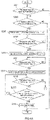
- FIG. 2 is a flow chart showing procedures of control of discharge from the battery 52 by the battery control device 60.
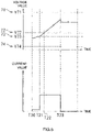
- FIG. 3 is a graph showing a current value and a voltage value during discharge of the battery 52.
- discharge of the battery 52 is performed when, for example, the power transmission unit 56 of the mobile battery 50 and the terminal power reception unit 84 of the portable terminal 80 are electrically connected to each other and, at the same time, charge is performed from the mobile battery 50 to the portable terminal 80.
- Discharge from the battery 52 is realized by the discharge controller 63 of the battery control device 60 shown in FIG. 1 .
- the discharge controller 63 controls discharge from the battery 52.
- an upper limit SOC 71 determined in advance and a lower limit SOC 72 which is determined in advance and which is lower than the upper limit SOC 71 are set to the battery 52.
- the upper limit SOC 71 and the lower limit SOC 72 are stored in the storage 61 shown in FIG. 1 .
- Specific numerical values of the upper limit SOC 71 and the lower limit SOC 72 are not particularly limited.
- the upper limit SOC 71 ranges from SOC 80% to SOC 95%, favorably ranges from SOC 80% to SOC 90%, and particularly favorably ranges from SOC 80% to SOC 85%.
- the lower limit SOC 72 ranges from SOC 0% to SOC 15%, favorably ranges from SOC 5% to SOC 15%, and particularly favorably ranges from SOC 10% to SOC 15%.
- a voltage value of the battery 52 corresponding to the upper limit SOC 71 is referred to as an upper limit voltage value V71 and a voltage value of the battery 52 corresponding to the lower limit SOC 72 is referred to as a lower limit voltage value V72.
- a SOC can be replaced with a voltage value.
- the present SOC 70 (refer to FIG. 2 ), the upper limit SOC 71, and the lower limit SOC 72 can be respectively replaced with a present voltage value of the battery 52 (hereinafter, referred to as a voltage value of the battery 52), the upper limit voltage value V71, and the lower limit voltage value V72.
- the discharge controller 63 shown in FIG. 1 controls discharge from the battery 52 until the present SOC 70 (refer to FIG. 2 ) at least becomes equal to the lower limit SOC 72.
- the discharge controller 63 controls discharge from the battery 52 until the voltage value of the battery 52 at least becomes equal to the lower limit voltage value V72.
- the lower limit SOC 72 is a lower limit value of the present SOC 70 when the battery 52 is discharged by a constant current (hereinafter, referred to as CC) discharge.
- step S101 shown in FIG. 2 the discharge controller 63 shown in FIG. 1 determines whether or not the present SOC 70 of the battery 52 is higher than the lower limit SOC 72. When it is determined at this point that the present SOC 70 is equal to or lower than the lower limit SOC 72, discharge from the battery 52 is not performed and the flow chart shown in FIG. 2 is ended.
- step S101 when it is determined in step S101 that the present SOC 70 of the battery 52 is higher than the lower limit SOC 72, an advance is made to step S103.
- step S103 the discharge controller 63 performs control of a CC discharge. For example, in FIG. 3 , the CC discharge is started at a time T10.
- step S105 the discharge controller 63 determines whether or not the present SOC 70 is equal to or lower than the lower limit SOC 72. At this point, when it is determined that the present SOC 70 is still higher than the lower limit SOC 72, processing of step S105 is executed once again.
- step S105 when it is determined in step S105 that the present SOC 70 is equal to or lower than the lower limit SOC 72, an advance is made to step S107.
- the present SOC 70 of the battery 52 becomes equal to or lower than the lower limit SOC 72 at a time T11.
- step S107 shown in FIG. 2 the discharge controller 63 performs control of a constant voltage (hereinafter, referred to as CV) discharge from the battery 52.
- CV constant voltage
- step S109 during the CV discharge, the discharge controller 63 determines whether or not the current value of the battery 52 at the present moment (hereinafter, referred to as a present current value) A10 is equal to or lower than a target current value A11.
- the target current value A11 is stored in advance in the storage 61 shown in FIG. 1 and is appropriately set. At this point, when it is determined that the present current value A10 is still higher than the target current value A11, processing of step S109 is executed once again. On the other hand, when it is determined in step S109 that the present current value A10 is equal to or lower than the target current value A11, an advance is made to step S111 and the control of the discharge from the battery 52 ends. In FIG. 3 , the present current value A10 becomes equal to or lower than the target current value A11 at a time T12 and the discharge from the battery 52 is ended.
- FIGS. 4A and 4B are flow charts showing procedures of control of charge to the battery 52 by the battery control device 60.
- FIG. 5 is a graph showing a current value and a voltage value during charge of the battery 52.
- control of charge to the battery 52 will be described with reference to the flow charts shown in FIGS. 4A and 4B .
- charge of the battery 52 is performed when the power feeding unit 21 of the power feeding device 20 and the power reception unit 54 of the mobile battery 50 are electrically connected to each other and, at the same time, charge is performed from the power feeding device 20 to the mobile battery 50.
- control of charge to the battery 52 is realized by the charge controller 65.
- the charge controller 65 controls charge to the battery 52.
- the charge controller 65 performs a pre-charge and a quick charge with respect to the battery 52.
- a pre-charge SOC 73 determined in advance is set to the battery 52.
- a voltage value of the battery 52 that corresponds to the pre-charge SOC 73 is referred to as a pre-charge voltage value V73.
- the pre-charge SOC 73 can be replaced with the pre-charge voltage value V73.
- the pre-charge SOC 73 is lower than the lower limit SOC 72 and is stored in the storage 61 shown in FIG. 1 in advance.
- the pre-charge SOC 73 ranges from SOC 0% to SOC 15%, favorably ranges from SOC 0% to SOC 10%, and particularly favorably ranges from SOC 0% to SOC 5%.
- the charge controller 65 performs the pre-charge until the present SOC 70 becomes equal to the pre-charge SOC 73 determined in advance and subsequently performs a quick charge.
- the charge controller 65 determines whether or not the present SOC 70 of the battery 52 is higher than a protection SOC 74.
- the protection SOC 74 refers to an upper limit value of the present SOC 70 when the battery 52 is being over-discharged. In other words, when the present SOC 70 is equal to or lower than the protection SOC 74, the battery 52 enters an over-discharged state.
- the protection SOC 74 is a value determined in advance and is stored in the storage 61 shown in FIG. 1 in advance. As shown in FIG. 5 , the protection SOC 74 is lower than the pre-charge SOC 73.
- a voltage value of the battery 52 that corresponds to the protection SOC 74 is referred to as a protection voltage value V74.
- V74 A voltage value of the battery 52 that corresponds to the protection SOC 74.
- step S201 shown in FIG. 4A when it is determined that the present SOC 70 of the battery 52 is equal to or lower than the protection SOC 74, charge to the battery 52 is favorably not performed. Therefore, when the present SOC 70 is equal to or lower than the protection SOC 74, charge to the battery 52 is not performed and the flow charts of FIGS. 4A and 4B are ended.
- step S201 when it is determined in step S201 that the present SOC 70 is higher than the protection SOC 74, an advance is made to step S203 shown in FIG. 4A .
- step S203 the charge controller 65 determines whether or not the present SOC 70 of the battery 52 is lower than the pre-charge SOC 73. At this point, when it is determined that the present SOC 70 is equal to or higher than the pre-charge SOC 73, a determination of NO is made in step S203. In this case, the control of a pre-charge to the battery 52 is not performed and an advance is made to the quick charge in step S209 shown in FIG. 4A .
- step S203 when it is determined in step S203 that the present SOC 70 of the battery 52 is lower than the pre-charge SOC 73, an advance is made to step S205 shown in FIG. 4A .
- step S205 in order to perform a pre-charge to the battery 52, the charge controller 65 performs control so as to perform charge (in this case, a CC charge) at a second charge rate R2.
- a pre-charge to the battery 52 is started.
- step S207 during the pre-charge, the charge controller 65 determines whether or not the present SOC 70 is equal to or higher than the pre-charge SOC 73. At this point, when it is determined that the present SOC 70 is lower than the pre-charge SOC 73, processing of step S207 is executed once again and the pre-charge is continued.
- step S207 when it is determined in step S207 that the present SOC 70 is equal to or higher than the pre-charge SOC 73, an advance is made to step S209 in order to end the pre-charge.
- step S209 in order to perform a quick charge to the battery 52, the charge controller 65 performs control so as to perform charge at a first charge rate R1 that is higher than the second charge rate R2 in the pre-charge.
- the quick charge in this case is a CC charge.
- FIG. 5 at a time T21, since the present SOC 70 of the battery 52 becomes equal to or higher than the pre-charge SOC 73, a quick charge is started.
- the first charge rate R1 in the quick charge ranges from 5C to 20C, favorably ranges from 10C to 20 C, and particularly favorably ranges from 15C to 20C.
- the second charge rate R2 in the pre-charge ranges from 0.05C to 0.5C, favorably ranges from 0.1C to 0.5C, and particularly favorably ranges from 0.3C to 0.5C.
- step S211 shown in FIG. 4A the charge controller 65 determines whether or not the present SOC 70 of the battery 52 is equal to or higher than the lower limit SOC 72. At this point, when it is determined that the present SOC 70 is lower than the lower limit SOC 72, processing of step S211 is executed once again.
- step S213 the charge controller 65 starts a count of the charge capacity according to a quick charge.
- the charge controller 65 starts a count of the charge capacity at a timing at which the present SOC 70 of the battery 52 becomes equal to the lower limit SOC 72.
- the charge capacity of which a count is started in step S215 is referred to as a quick charge capacity C10.
- the present SOC 70 of the battery 52 becomes equal to or higher than the lower limit SOC 72 and a count of the quick charge capacity C10 is started.
- the charge controller 65 determines whether or not the present SOC 70 of the battery 52 is lower than the upper limit SOC 71 during the quick charge.
- the present SOC 70 is equal to or higher than the upper limit SOC 71, the battery 52 can be described as being in an overcharged state.
- an advance is made to step S217.
- the charge controller 65 determines whether or not the quick charge capacity C10 of the battery 52 is smaller than a target charge capacity C11.
- the target charge capacity C11 is a charge capacity to be charged to the battery 52 in a quick charge and is a charge capacity to be a target in the quick charge.
- a SOC when the battery 52 is fully charged will be referred to as a fully charged SOC.
- the target charge capacity C11 is a charge capacity to be charged to the battery 52 when the present SOC 70 of the battery 52 changes from the lower limit SOC 72 to the fully charged SOC.
- a charge capacity of the target charge capacity C11 can be obtained by performing a CC charge for an elapsed time determined in advance. In this case, the target charge capacity C11 is stored in the storage 61 in advance.
- step S217 When it is determined in step S217 that the quick charge capacity C10 of the battery 52 is smaller than the target charge capacity C11, a return is made to step S215 to continue the quick charge.
- step S217 when the quick charge capacity C10 of the battery 52 is equal to or larger than the target charge capacity C11 in step S217, an advance is made to step S219, the quick charge ends, and the control of the charge to the battery 52 by the charge controller 65 is ended.
- the quick charge capacity C10 becomes equal to or larger than the target charge capacity C11 and the charge to the battery 52 ends.
- step S215 in FIG. 4A described above When it is determined in step S215 in FIG. 4A described above that the present SOC 70 of the battery 52 is equal to or higher than the upper limit SOC 71, since the battery 52 is in an overcharged state, an advance is made to step S221 in FIG. 4B .
- step S221 the charge controller 65 switches from a CC charge to a CV charge in the quick charge to the battery 52.
- step S223 in FIG. 4B the charge controller 65 determines whether or not the quick charge capacity C10 of the battery 52 is smaller than the target charge capacity C11 stored in the storage 61 in a similar manner to step S217 in FIG. 4A .
- step S223 is executed once again to continue the CV charge.
- step S223 when it is determined in step S223 that the quick charge capacity C10 of the battery 52 is equal to or larger than the target charge capacity C11, an advance is made to step S225, the quick charge (CV charge) ends, and the control of the charge to the battery 52 by the charge controller 65 is ended.
- the mobile battery 50 includes the casing 51, the battery 52, the power transmission unit 56, and the battery control device 60.
- the battery 52 is arranged inside the casing 51 and can be charged at a charge rate of 5C or higher.
- the power transmission unit 56 is arranged inside the casing 51.
- the battery control device 60 is connected to the battery 52 and the power transmission unit 56.
- the battery control device 60 includes: the storage 61; a discharge controller 63 which controls discharge from the battery 52; and a charge controller 65 which controls charge to the battery 52.
- the storage 61 stores the target charge capacity C11 (refer to FIG. 4A ) to be charged to the battery 52.
- the target charge capacity C11 refers to a charge capacity to be charged in a quick charge.
- the discharge controller 63 is configured to be capable of performing at least discharge from the battery 52 to the lower limit SOC 72 determined in advance.
- the charge controller 65 is configured to start a count of the quick charge capacity C10 at a timing at which the present SOC 70 of the battery 52 becomes equal to the lower limit SOC 72 (refer to step S213 in FIG. 4A ).
- the charge controller 65 is configured to end the charge to the battery 52.
- the SOC of the battery 52 can fall below the lower limit SOC 72 due to a self-discharge or the like.
- the present SOC 70 of the battery 52 after the charge when the quick charge capacity C10 becomes equal to the target charge capacity C11 becomes lower than the fully charged SOC described above. This is because the target charge capacity C11 is set to a charge capacity to be charged to the battery 52 when the present SOC 70 changes from the lower limit SOC 72 to the fully charged SOC.
- the target charge capacity C11 is invariant in the present embodiment, for example, the target charge capacity C11 may conceivably be made variable in consideration of a charge capacity that is self-discharged. However, since the charge capacity that is self-discharged varies, accurately measuring the self-discharged charge capacity and setting the target charge capacity C11 every time charge is performed complicates control. Therefore, the target charge capacity C11 is favorably invariant or, in other words, constant.
- a count of the quick charge capacity C10 is started at a timing at which the present SOC 70 of the battery 52 becomes equal to the lower limit SOC 72 during charge in a state where the present SOC 70 of the battery 52 is lower than the lower limit SOC 72, the timing at which the count of the quick charge capacity C10 can be temporally shifted to a later timing. Therefore, by ending the charge once the target charge capacity C11 stored in the storage 61 is reached after starting the count of the quick charge capacity C10, since the SOC of the battery 52 can be adjusted to the expected SOC after the charge (in other words, the fully charged SOC), an appropriate charge can be performed.
- the charge controller 65 is configured to perform charge (in this case, a pre-charge) of the battery 52 (refer to step S205 in FIG. 4A ) at the second charge rate R2 that is lower than the first charge rate R1 determined in advance when the charge is started in a state where the present SOC 70 of the battery 52 is lower than the pre-charge SOC 73 determined in advance which is lower than the lower limit SOC 72 as in step S203 in FIG. 4A .
- the charge controller 65 is configured to perform charge (in this case, a quick charge) of the battery 52 at the first charge rate R1 as in step S209 when the present SOC 70 of the battery 52 is equal to or higher than the pre-charge SOC 73 as in step S207 in FIG. 4A .
- a longer charge time for a pre-charge results in a longer total charge time of the battery 52.
- a total charge time refers to a time that is a sum of a charge time required by a pre-charge and a charge time required by a quick charge.
- the pre-charge SOC 73 is set lower than the lower limit SOC 72 during discharge. Therefore, charge to the battery 52 by a pre-charge ends when the present SOC 70 is lower than the lower limit SOC 72. Accordingly, since the charge time required by a pre-charge can be shortened, the total charge time of the battery 52 can be reduced.
- a pre-charge is performed in order to reduce a voltage difference among the plurality of battery cells 53 (refer to FIG. 1 ) included in the battery 52 and to equalize the voltage difference among the plurality of battery cells 53. Therefore, since a quick charge is performed with respect to the plurality of battery cells 53 of which voltage values have been equalized, the battery 52 can be set to a fully charged state while suppressing a variation in states of charge of the battery cells 53.
- setting the pre-charge SOC 73 lower than the lower limit SOC 72 as shown in FIG. 5 enables the charge time required by a pre-charge to be shortened. Even when the charge time required by a pre-charge is shortened, the voltage values of the plurality of battery cells 53 can be equalized by the pre-charge. Therefore, even in the present embodiment, the battery 52 can be charged in a stable manner.
- the power transmission unit 56 shown in FIG. 1 includes a wireless power transmission device. This enables, for example, power to be supplied from the power transmission unit 56 to the portable terminal 80 and charge to the portable terminal 80 (more specifically, the built-in battery 82) to be performed while the mobile battery 50 is being carried around.
- the portable terminal 80 can be readily charged by arranging the mobile battery 50 within a predetermined range from the portable terminal 80 without regard to a state of connection between the mobile battery 50 and the portable terminal 80.
- the battery 52 and the battery control device 60 are included in the mobile battery 50 and are realized by the mobile battery 50.
- the realization of the battery control device 60 is not limited to the realization by the mobile battery 50.
- FIG. 6 is a conceptual diagram of a charging system 10A according to another embodiment.
- the charging system 10A includes a power feeding device 20 and a portable terminal 80A.
- a mobile battery 50 such as that shown in FIG. 1 is omitted.
- the portable terminal 80A includes a high-output battery 52, a power reception unit 54, and a battery control device 60.
- the battery 52, the power reception unit 54, and the battery control device 60 of the portable terminal 80A are respectively the same as the battery 52, the power reception unit 54, and the battery control device 60 of the mobile battery 50 shown in FIG. 1 . In this manner, even in a case where the high-output battery 52, the power reception unit 54, and the battery control device 60 are included in the portable terminal 80A, a similar effect to the embodiment described above is produced.
Landscapes
- Engineering & Computer Science (AREA)
- Power Engineering (AREA)
- Manufacturing & Machinery (AREA)
- Chemical & Material Sciences (AREA)
- Chemical Kinetics & Catalysis (AREA)
- Electrochemistry (AREA)
- General Chemical & Material Sciences (AREA)
- Computer Networks & Wireless Communication (AREA)
- Microelectronics & Electronic Packaging (AREA)
- Charge And Discharge Circuits For Batteries Or The Like (AREA)
- Secondary Cells (AREA)
Abstract
Description
- The present invention relates to a battery control device and a mobile battery.
- For example,
WO 2014/156041 discloses a battery system which includes a plurality of battery units and which performs charge and discharge with respect to the battery units. In the battery system disclosed herein, charging the plurality of battery units includes an equilibrated charge mode and a normal charge mode. The normal charge mode is executed after the equilibrated charge mode. - In the equilibrated charge mode, for example, when a voltage difference is created among the plurality of battery units, a pre-charge is executed with respect to the plurality of battery units. The pre-charge in the equilibrated charge mode reduces the voltage difference among the plurality of battery units and enables voltage values of the respective battery units to be equalized. In the normal charge mode, a normal charge is performed with respect to the respective battery units, of which voltage values have been equalized in the equilibrated charge mode. Therefore, each battery unit can be fully charged while suppressing a variation in states of charge of the respective battery units.
- For example, in a normal charge in the normal charge mode, charge of a predetermined charge capacity is performed in the normal charge by performing a constant current charge for a predetermined amount of time. During discharge with respect to the battery unit, the battery unit is discharged until a state of charge (hereinafter, referred to as a SOC) of the battery unit drops to a predetermined SOC. Subsequently, the SOC of the battery unit may fall below the predetermined SOC due to a self-discharge or the like. When charge (for example, the normal charge in the normal charge mode disclosed in
WO 2014/156041 ) is performed with respect to the battery unit in a state where the SOC of the battery unit is lower than the predetermined SOC, there is a concern that the SOC of the battery unit after the charge ends up being lower than a SOC expected after the charge and an appropriate charge cannot be performed. - A battery control device proposed herein includes: a discharge controller which controls discharge from a battery; a charge controller which controls charge to the battery; and a storage which stores a charge capacity to be charged to the battery. The discharge controller is configured to be capable of performing at least discharge from the battery to a lower limit SOC determined in advance. The charge controller is configured to start a count of the charge capacity at a timing at which a SOC of the battery becomes equal to the lower limit SOC when charge is started in a state where the SOC of the battery is lower than the lower limit SOC, and to end the charge to the battery once the charge capacity having been charged after starting the count becomes equal to the charge capacity stored in the storage.
- For example, when charge is started in a state where the SOC of the battery is lower than the lower limit SOC due to a self-discharge or the like, on the supposition that the count of the charge capacity is started at a timing of the start of charge to the battery, there is a concern that the SOC of the battery after charge equivalent to a charge capacity stored in the storage is performed becomes lower than an expected SOC after the charge. However, according to the battery control device proposed herein, since a count of the charge capacity is started at a timing at which the SOC of the battery becomes equal to the lower limit SOC when charge is started in a state where the SOC of the battery is lower than the lower limit SOC, the timing at which the count of the charge capacity is started can be temporally shifted to a later timing. Therefore, by ending the charge once the charge capacity stored in the storage is reached after starting the count of the charge capacity, since the SOC of the battery can be adjusted to the expected SOC after the charge, an appropriate charge can be performed.
- In the battery control device proposed herein, the charge controller may be configured to charge the battery at a second charge rate that is lower than a first charge rate determined in advance when the charge is started in a state where the SOC of the battery is lower than a pre-charge SOC determined in advance, which is lower than the lower limit SOC and to charge the battery at the first charge rate when the SOC of the battery is equal to or higher than the pre-charge SOC.
- A mobile battery proposed herein includes: a casing; a battery which is arranged inside the casing and which can be charged at a charge rate equal to or higher than 5C; a power transmission unit which is arranged inside the casing; and a battery control device which is connected to the battery and to the power transmission unit. The battery control device includes: a discharge controller which controls discharge from the battery; a charge controller which controls charge to the battery; and a storage which stores a charge capacity to be charged to the battery. The discharge controller is configured to be capable of performing at least discharge from the battery to a lower limit SOC determined in advance. The charge controller is configured to start a count of the charge capacity at a timing at which a SOC of the battery becomes equal to the lower limit SOC when charge is started in a state where the SOC of the battery is lower than the lower limit SOC, and to end the charge to the battery once the charge capacity having been charged after starting the count becomes equal to the charge capacity stored in the storage.
- In the mobile battery proposed herein, the power transmission unit may include a wireless power transmission device.
-
-
FIG. 1 is a block diagram schematically showing a charging system according to an embodiment; -
FIG. 2 is a flow chart showing procedures of control of discharge from a battery by a battery control device; -
FIG. 3 is a graph showing a current value and a voltage value during discharge of a battery; -
FIG. 4A is a flow chart showing procedures of control of charge to a battery by the battery control device; -
FIG. 4B is a flow chart showing procedures of control of charge to a battery by the battery control device; -
FIG. 5 is a graph showing a current value and a voltage value during charge of a battery; and -
FIG. 6 is a block diagram schematically showing a charging system according to another embodiment. - Hereinafter, an embodiment of the battery control device and the mobile battery disclosed herein will be described with reference to the drawings. It should be noted that the embodiments described herein naturally are not intended to limit the present invention. The present invention is not limited to the embodiments described herein unless specifically mentioned otherwise. It will be recognized that the respective drawings are merely schematic renderings and therefore do not necessarily reflect actual objects. In addition, members and portions that produce same effects will be described using same reference signs and overlapping descriptions will be omitted as deemed appropriate.
-
FIG. 1 is a block diagram schematically showing acharging system 10 according to the present embodiment. In the present embodiment, the battery control device and the mobile battery are realized by thecharging system 10 shown inFIG. 1 . First, a configuration of thecharging system 10 will be described. Thecharging system 10 includes apower feeding device 20, amobile battery 50, and aportable terminal 80. In thecharging system 10, a quick charge is performed from thepower feeding device 20 to themobile battery 50. In addition, for example, theportable terminal 80 is charged using the chargedmobile battery 50. - The
power feeding device 20, themobile battery 50, and theportable terminal 80 appropriately include a control device. The control device is an device for controlling various types of processing by each device. The control device can be embodied by a computer that is driven by a program determined in advance. Specifically, each function of the control device is processed by an arithmetic unit (also referred to as a processor, a CPU (Central Processing Unit), or an MPU (Micro-processing unit)) and a storage device (a memory, a hard disk, or the like) of each computer that constitutes the control device. For example, each component of the control device can be embodied as a database that stores data to be embodied by a computer in a format determined in advance, a data structure, a processing module that performs predetermined arithmetic processing in accordance with a program determined in advance, and the like or as a part thereof. The control devices built into the respective devices may be configured to communicate data and function in collaboration with each other. - The
power feeding device 20 has apower feeding unit 21, apower supply unit 22, and a powerfeed control device 23. Thepower feeding unit 21 is configured to charge themobile battery 50. For example, thepower feeding unit 21 is capable of transmitting (in other words, capable of supplying) power to themobile battery 50 and, favorably, capable of supplying power at high output. For example, thepower feeding unit 21 is a wireless or, in other words, a contactless power feeding device. Alternatively, thepower feeding unit 21 may be a contact-type power feeding device. - The
power supply unit 22 is connected to anexternal power supply 30. Thepower supply unit 22 is a device which receives power from theexternal power supply 30 and which supplies power to external devices such as themobile battery 50 and theportable terminal 80 via thepower feeding unit 21. Theexternal power supply 30 may be a 100-V or 200-V AC power supply. Thepower supply unit 22 may include an AC/DC converter. - The power
feed control device 23 is electrically connected to thepower feeding unit 21 and thepower supply unit 22. The powerfeed control device 23 controls power that is supplied from thepower feeding unit 21 to themobile battery 50. In addition, the powerfeed control device 23 controls power that is received by thepower supply unit 22 from theexternal power supply 30. - The
mobile battery 50 includes acasing 51, abattery 52, apower reception unit 54, apower transmission unit 56, and abattery control device 60. Thecasing 51 has a predetermined internal space. Thebattery 52, thepower reception unit 54, thepower transmission unit 56, and thebattery control device 60 are arranged inside thecasing 51. - The
battery 52 is designed to be capable of a quick charge and is constituted by a high-output battery. For example, battery technology that is applied to a power supply for driving a so-called hybrid vehicle is favorably transferred to thebattery 52. Thebattery 52 is capable of performing charge at a charge rate of 5C or higher (for example, 8C or higher or 10C or higher). Thebattery 52 is favorably designed to minimize deterioration even when performing charge at a current value corresponding to a charge rate of 5C or higher. - In the present specification, a magnitude of a current that causes a theoretical capacity of the
battery 52 to be fully charged or discharged in one hour is defined as 1C. For example, when the capacity of thebattery 52 is 2 Ah, 1C equates to 2 A. 3C corresponds to a current value that is three times 1C and, in the example described above, signifies a current value at which the theoretical capacity is fully charged or discharged in 20 minutes. For example, when the charge rate of thebattery 52 is 5C, charge of around 15% of the theoretical capacity can be realized by charge of around three minutes. Charge of around 25% of the theoretical capacity of thebattery 52 can be realized by charge of around five minutes. In the future, as battery technology that is applied to a power supply for driving a hybrid vehicle is further applied, charge in an even shorter amount of time can be realized by an even higher charge current value. Therefore, it is expected that thebattery 52 can be charged with required power merely within several to several ten seconds. - Although not illustrated, the
mobile battery 50 according to the present embodiment may include a so-called high-capacity battery in addition to the high-output battery 52. For example, the high-capacity battery allows charge and discharge to be performed at a charge rate of around 1C to 3C. For example, the high-capacity battery has an energy density of around 400 Wh/L to 800 Wh/L. - In the present embodiment, the
battery 52 has abattery cell 53. While thebattery 52 may only have onebattery cell 53, in the present embodiment, thebattery 52 has a plurality ofbattery cells 53. The number of thebattery cells 53 is not particularly limited. When there are a plurality ofbattery cells 53, the plurality ofbattery cells 53 may be either connected in series or connected in parallel. - Power is supplied to the
power reception unit 54 from thepower feeding unit 21 of thepower feeding device 20. Thepower reception unit 54 is favorably capable of receiving high output. In this case, thepower reception unit 54 includes a wireless power reception device. For example, power is supplied to the wireless power reception device from thepower feeding unit 21 of thepower feeding device 20 by a contactless power feeding (wireless power feeding) system. As the contactless power feeding system, an electromagnetic induction system, a magnetic field resonance system, an electric field coupling system, a radio wave reception system, or the like can be adopted. Alternatively, thepower reception unit 54 may be a contact-type power receiving device. - The
power transmission unit 56 is configured to charge theportable terminal 80 and is capable of transmitting power. Thepower transmission unit 56 includes a wireless power transmission device. For example, the wireless power transmission device supplies power to a terminal power reception unit 84 (to be described later) of theportable terminal 80 by a contactless power feeding (wireless power feeding) system. Alternatively, thepower transmission unit 56 may be a contact-type power transmission device. In the present embodiment, a current value of a power feed from thepower transmission unit 56 to theportable terminal 80 may be controlled so that, for example, power is fed at a current value kept low enough so as minimize deterioration of a built-in battery 82 (to be described later) of theportable terminal 80. - According to the
mobile battery 50 described above, required power can be obtained in a short period of time by a quick charge from thepower feeding device 20. Therefore, a user need not wait for a long time to be charged at a location where thepower feeding device 20 is installed. In addition, power may be slowly fed from themobile battery 50 to theportable terminal 80 at a current value determined so as to prevent the built-inbattery 82 of the portable terminal 80 from deteriorating. For example, charge may be performed from themobile battery 50 to theportable terminal 80 after charge has been performed from thepower feeding device 20 to themobile battery 50. - The
battery control device 60 controls charge and discharge of thebattery 52. Although not illustrated, thebattery control device 60 includes a charge/discharge control circuit which controls charge and discharge of thebattery 52 and a battery protection circuit which protects thebattery 52 from being overcharged or over-discharged. Thebattery control device 60 is electrically connected to thebattery 52, thepower reception unit 54, and thepower transmission unit 56. Thebattery control device 60 includes astorage 61, adischarge controller 63, and acharge controller 65. Details of thestorage 61, thedischarge controller 63, and thecharge controller 65 will be provided later. - Examples of the
portable terminal 80 include a smartphone, a mobile phone, a tablet terminal, and a mobile PC. Theportable terminal 80 includes the built-inbattery 82, the terminalpower reception unit 84, and aterminal control device 86. - The built-in
battery 82 is a battery to act as a power supply for supplying power to theportable terminal 80. The built-inbattery 82 favorably has a required charge capacity that is needed to enable theportable terminal 80 to be continuously used for a certain amount of time. - The terminal
power reception unit 84 is electrically connected to themobile battery 50. The terminalpower reception unit 84 includes a wireless power reception device such as that described above. Alternatively, the terminalpower reception unit 84 may be a contact-type power receiving device. In this case, power is supplied from thepower transmission unit 56 of themobile battery 50 to the terminalpower reception unit 84 to charge the built-inbattery 82. - The
terminal control device 86 is electrically connected to the built-inbattery 82 and the terminalpower reception unit 84. Theterminal control device 86 controls power supplied through the terminalpower reception unit 84 and, at the same time, controls charge to the built-inbattery 82. In this case, for example, theterminal control device 86 has a charge control circuit which controls charge to the built-inbattery 82 and a battery protection circuit which protects the built-inbattery 82 from being overcharged. - Next, control of charge and discharge of the
battery 52 by thebattery control device 60 in themobile battery 50 will be described. Hereinafter, charge and discharge of thebattery 52 signify charge and discharge of the plurality ofbattery cells 53. - In the present embodiment, charge and discharge of the
battery 52 are controlled based on a state of charge (hereinafter, referred to as a SOC) of thebattery 52. In the following description, the SOC of thebattery 52 at the present moment will be referred to as a present SOC. -
FIG. 2 is a flow chart showing procedures of control of discharge from thebattery 52 by thebattery control device 60.FIG. 3 is a graph showing a current value and a voltage value during discharge of thebattery 52. Next, control of discharge from thebattery 52 by thebattery control device 60 will be described with reference to the flow chart shown inFIG. 2 . In the present embodiment, as shown inFIG. 1 , discharge of thebattery 52 is performed when, for example, thepower transmission unit 56 of themobile battery 50 and the terminalpower reception unit 84 of theportable terminal 80 are electrically connected to each other and, at the same time, charge is performed from themobile battery 50 to theportable terminal 80. Discharge from thebattery 52 is realized by thedischarge controller 63 of thebattery control device 60 shown inFIG. 1 . Thedischarge controller 63 controls discharge from thebattery 52. - In the present embodiment, as shown in
FIG. 3 , anupper limit SOC 71 determined in advance and alower limit SOC 72 which is determined in advance and which is lower than theupper limit SOC 71 are set to thebattery 52. Theupper limit SOC 71 and thelower limit SOC 72 are stored in thestorage 61 shown inFIG. 1 . Specific numerical values of theupper limit SOC 71 and thelower limit SOC 72 are not particularly limited. For example, theupper limit SOC 71 ranges fromSOC 80% to SOC 95%, favorably ranges fromSOC 80% to SOC 90%, and particularly favorably ranges fromSOC 80% to SOC 85%. For example, thelower limit SOC 72 ranges from SOC 0% to SOC 15%, favorably ranges from SOC 5% to SOC 15%, and particularly favorably ranges fromSOC 10% to SOC 15%. - In this case, a voltage value of the
battery 52 corresponding to theupper limit SOC 71 is referred to as an upper limit voltage value V71 and a voltage value of thebattery 52 corresponding to thelower limit SOC 72 is referred to as a lower limit voltage value V72. In the following description, a SOC can be replaced with a voltage value. For example, the present SOC 70 (refer toFIG. 2 ), theupper limit SOC 71, and thelower limit SOC 72 can be respectively replaced with a present voltage value of the battery 52 (hereinafter, referred to as a voltage value of the battery 52), the upper limit voltage value V71, and the lower limit voltage value V72. - The
discharge controller 63 shown inFIG. 1 controls discharge from thebattery 52 until the present SOC 70 (refer toFIG. 2 ) at least becomes equal to thelower limit SOC 72. In other words, thedischarge controller 63 controls discharge from thebattery 52 until the voltage value of thebattery 52 at least becomes equal to the lower limit voltage value V72. In the present embodiment, thelower limit SOC 72 is a lower limit value of thepresent SOC 70 when thebattery 52 is discharged by a constant current (hereinafter, referred to as CC) discharge. - In this case, first, in step S101 shown in
FIG. 2 , thedischarge controller 63 shown inFIG. 1 determines whether or not thepresent SOC 70 of thebattery 52 is higher than thelower limit SOC 72. When it is determined at this point that thepresent SOC 70 is equal to or lower than thelower limit SOC 72, discharge from thebattery 52 is not performed and the flow chart shown inFIG. 2 is ended. - On the other hand, when it is determined in step S101 that the
present SOC 70 of thebattery 52 is higher than thelower limit SOC 72, an advance is made to step S103. In step S103, thedischarge controller 63 performs control of a CC discharge. For example, inFIG. 3 , the CC discharge is started at a time T10. - Next, in step S105 shown in
FIG. 2 , during the CC discharge, thedischarge controller 63 determines whether or not thepresent SOC 70 is equal to or lower than thelower limit SOC 72. At this point, when it is determined that thepresent SOC 70 is still higher than thelower limit SOC 72, processing of step S105 is executed once again. - On the other hand, when it is determined in step S105 that the
present SOC 70 is equal to or lower than thelower limit SOC 72, an advance is made to step S107. InFIG. 3 , thepresent SOC 70 of thebattery 52 becomes equal to or lower than thelower limit SOC 72 at a time T11. In step S107 shown inFIG. 2 , thedischarge controller 63 performs control of a constant voltage (hereinafter, referred to as CV) discharge from thebattery 52. - Next, in step S109, during the CV discharge, the
discharge controller 63 determines whether or not the current value of thebattery 52 at the present moment (hereinafter, referred to as a present current value) A10 is equal to or lower than a target current value A11. The target current value A11 is stored in advance in thestorage 61 shown inFIG. 1 and is appropriately set. At this point, when it is determined that the present current value A10 is still higher than the target current value A11, processing of step S109 is executed once again. On the other hand, when it is determined in step S109 that the present current value A10 is equal to or lower than the target current value A11, an advance is made to step S111 and the control of the discharge from thebattery 52 ends. InFIG. 3 , the present current value A10 becomes equal to or lower than the target current value A11 at a time T12 and the discharge from thebattery 52 is ended. -
FIGS. 4A and4B are flow charts showing procedures of control of charge to thebattery 52 by thebattery control device 60.FIG. 5 is a graph showing a current value and a voltage value during charge of thebattery 52. Next, control of charge to thebattery 52 will be described with reference to the flow charts shown inFIGS. 4A and4B . In the present embodiment, as shown inFIG. 1 , charge of thebattery 52 is performed when thepower feeding unit 21 of thepower feeding device 20 and thepower reception unit 54 of themobile battery 50 are electrically connected to each other and, at the same time, charge is performed from thepower feeding device 20 to themobile battery 50. In the present embodiment, control of charge to thebattery 52 is realized by thecharge controller 65. Thecharge controller 65 controls charge to thebattery 52. - In the present embodiment, the
charge controller 65 performs a pre-charge and a quick charge with respect to thebattery 52. In this case, as shown inFIG. 5 , apre-charge SOC 73 determined in advance is set to thebattery 52. A voltage value of thebattery 52 that corresponds to thepre-charge SOC 73 is referred to as a pre-charge voltage value V73. In the following description, when a SOC is replaced with a voltage value, thepre-charge SOC 73 can be replaced with the pre-charge voltage value V73. Thepre-charge SOC 73 is lower than thelower limit SOC 72 and is stored in thestorage 61 shown inFIG. 1 in advance. For example, thepre-charge SOC 73 ranges from SOC 0% to SOC 15%, favorably ranges from SOC 0% toSOC 10%, and particularly favorably ranges from SOC 0% to SOC 5%. - The
charge controller 65 performs the pre-charge until thepresent SOC 70 becomes equal to thepre-charge SOC 73 determined in advance and subsequently performs a quick charge. - In this case, first, in step S201 shown in
FIG. 4A , thecharge controller 65 determines whether or not thepresent SOC 70 of thebattery 52 is higher than aprotection SOC 74. Theprotection SOC 74 as used herein refers to an upper limit value of thepresent SOC 70 when thebattery 52 is being over-discharged. In other words, when thepresent SOC 70 is equal to or lower than theprotection SOC 74, thebattery 52 enters an over-discharged state. Theprotection SOC 74 is a value determined in advance and is stored in thestorage 61 shown inFIG. 1 in advance. As shown inFIG. 5 , theprotection SOC 74 is lower than thepre-charge SOC 73. A voltage value of thebattery 52 that corresponds to theprotection SOC 74 is referred to as a protection voltage value V74. Hereinafter, when a SOC is replaced with a voltage value, theprotection SOC 74 can be replaced with the protection voltage value V74. - In the present embodiment, in step S201 shown in
FIG. 4A , when it is determined that thepresent SOC 70 of thebattery 52 is equal to or lower than theprotection SOC 74, charge to thebattery 52 is favorably not performed. Therefore, when thepresent SOC 70 is equal to or lower than theprotection SOC 74, charge to thebattery 52 is not performed and the flow charts ofFIGS. 4A and4B are ended. - On the other hand, when it is determined in step S201 that the
present SOC 70 is higher than theprotection SOC 74, an advance is made to step S203 shown inFIG. 4A . In step S203, thecharge controller 65 determines whether or not thepresent SOC 70 of thebattery 52 is lower than thepre-charge SOC 73. At this point, when it is determined that thepresent SOC 70 is equal to or higher than thepre-charge SOC 73, a determination of NO is made in step S203. In this case, the control of a pre-charge to thebattery 52 is not performed and an advance is made to the quick charge in step S209 shown inFIG. 4A . - On the other hand, when it is determined in step S203 that the
present SOC 70 of thebattery 52 is lower than thepre-charge SOC 73, an advance is made to step S205 shown inFIG. 4A . In step S205, in order to perform a pre-charge to thebattery 52, thecharge controller 65 performs control so as to perform charge (in this case, a CC charge) at a second charge rate R2. InFIG. 5 , at a time T20, since thepresent SOC 70 of thebattery 52 is lower than thepre-charge SOC 73, a pre-charge to thebattery 52 is started. - Next, in step S207, during the pre-charge, the
charge controller 65 determines whether or not thepresent SOC 70 is equal to or higher than thepre-charge SOC 73. At this point, when it is determined that thepresent SOC 70 is lower than thepre-charge SOC 73, processing of step S207 is executed once again and the pre-charge is continued. - On the other hand, when it is determined in step S207 that the
present SOC 70 is equal to or higher than thepre-charge SOC 73, an advance is made to step S209 in order to end the pre-charge. In step S209, in order to perform a quick charge to thebattery 52, thecharge controller 65 performs control so as to perform charge at a first charge rate R1 that is higher than the second charge rate R2 in the pre-charge. The quick charge in this case is a CC charge. InFIG. 5 , at a time T21, since thepresent SOC 70 of thebattery 52 becomes equal to or higher than thepre-charge SOC 73, a quick charge is started. - In this case, for example, the first charge rate R1 in the quick charge ranges from 5C to 20C, favorably ranges from 10C to 20 C, and particularly favorably ranges from 15C to 20C. For example, the second charge rate R2 in the pre-charge ranges from 0.05C to 0.5C, favorably ranges from 0.1C to 0.5C, and particularly favorably ranges from 0.3C to 0.5C.
- Next, in step S211 shown in
FIG. 4A , thecharge controller 65 determines whether or not thepresent SOC 70 of thebattery 52 is equal to or higher than thelower limit SOC 72. At this point, when it is determined that thepresent SOC 70 is lower than thelower limit SOC 72, processing of step S211 is executed once again. - On the other hand, when it is determined in step S211 that the
present SOC 70 is equal to or higher than thelower limit SOC 72, an advance is made to step S213. In step S213, thecharge controller 65 starts a count of the charge capacity according to a quick charge. In other words, when charge is started in a state where thepresent SOC 70 of thebattery 52 is lower than thelower limit SOC 72, thecharge controller 65 starts a count of the charge capacity at a timing at which thepresent SOC 70 of thebattery 52 becomes equal to thelower limit SOC 72. In the present embodiment, the charge capacity of which a count is started in step S215 is referred to as a quick charge capacity C10. InFIG. 5 , at a time T22, thepresent SOC 70 of thebattery 52 becomes equal to or higher than thelower limit SOC 72 and a count of the quick charge capacity C10 is started. - After the count of the quick charge capacity C10 is started in step S213, subsequently in step S215, the
charge controller 65 determines whether or not thepresent SOC 70 of thebattery 52 is lower than theupper limit SOC 71 during the quick charge. When thepresent SOC 70 is equal to or higher than theupper limit SOC 71, thebattery 52 can be described as being in an overcharged state. At this point, when it is determined that thepresent SOC 70 is lower than theupper limit SOC 71, an advance is made to step S217. - In step S217, the
charge controller 65 determines whether or not the quick charge capacity C10 of thebattery 52 is smaller than a target charge capacity C11. In the present embodiment, the target charge capacity C11 is a charge capacity to be charged to thebattery 52 in a quick charge and is a charge capacity to be a target in the quick charge. In this case, for example, a SOC when thebattery 52 is fully charged will be referred to as a fully charged SOC. The target charge capacity C11 is a charge capacity to be charged to thebattery 52 when thepresent SOC 70 of thebattery 52 changes from thelower limit SOC 72 to the fully charged SOC. For example, a charge capacity of the target charge capacity C11 can be obtained by performing a CC charge for an elapsed time determined in advance. In this case, the target charge capacity C11 is stored in thestorage 61 in advance. - When it is determined in step S217 that the quick charge capacity C10 of the
battery 52 is smaller than the target charge capacity C11, a return is made to step S215 to continue the quick charge. - On the other hand, when the quick charge capacity C10 of the
battery 52 is equal to or larger than the target charge capacity C11 in step S217, an advance is made to step S219, the quick charge ends, and the control of the charge to thebattery 52 by thecharge controller 65 is ended. InFIG. 5 , at a time T23, the quick charge capacity C10 becomes equal to or larger than the target charge capacity C11 and the charge to thebattery 52 ends. - When it is determined in step S215 in
FIG. 4A described above that thepresent SOC 70 of thebattery 52 is equal to or higher than theupper limit SOC 71, since thebattery 52 is in an overcharged state, an advance is made to step S221 inFIG. 4B . In step S221, thecharge controller 65 switches from a CC charge to a CV charge in the quick charge to thebattery 52. - Subsequently, in step S223 in
FIG. 4B , thecharge controller 65 determines whether or not the quick charge capacity C10 of thebattery 52 is smaller than the target charge capacity C11 stored in thestorage 61 in a similar manner to step S217 inFIG. 4A . When it is determined in step S223 that the quick charge capacity C10 of thebattery 52 is smaller than the target charge capacity C11, step S223 is executed once again to continue the CV charge. - On the other hand, when it is determined in step S223 that the quick charge capacity C10 of the
battery 52 is equal to or larger than the target charge capacity C11, an advance is made to step S225, the quick charge (CV charge) ends, and the control of the charge to thebattery 52 by thecharge controller 65 is ended. - As described above, in the present embodiment, as shown in
FIG. 1 , themobile battery 50 includes thecasing 51, thebattery 52, thepower transmission unit 56, and thebattery control device 60. Thebattery 52 is arranged inside thecasing 51 and can be charged at a charge rate of 5C or higher. Thepower transmission unit 56 is arranged inside thecasing 51. Thebattery control device 60 is connected to thebattery 52 and thepower transmission unit 56. Thebattery control device 60 includes: thestorage 61; adischarge controller 63 which controls discharge from thebattery 52; and acharge controller 65 which controls charge to thebattery 52. Thestorage 61 stores the target charge capacity C11 (refer toFIG. 4A ) to be charged to thebattery 52. In this case, the target charge capacity C11 refers to a charge capacity to be charged in a quick charge. As shown inFIG. 3 , thedischarge controller 63 is configured to be capable of performing at least discharge from thebattery 52 to thelower limit SOC 72 determined in advance. When charge is started in a state where thepresent SOC 70 of thebattery 52 is lower than thelower limit SOC 72, thecharge controller 65 is configured to start a count of the quick charge capacity C10 at a timing at which thepresent SOC 70 of thebattery 52 becomes equal to the lower limit SOC 72 (refer to step S213 inFIG. 4A ). In addition, when a charge capacity having been charged after the count is started (in this case, the quick charge capacity C10) becomes equal to the target charge capacity C11 stored in thestorage 61, thecharge controller 65 is configured to end the charge to thebattery 52. - For example, the SOC of the
battery 52 can fall below thelower limit SOC 72 due to a self-discharge or the like. In this case, supposing that the count of the quick charge capacity C10 is started during a quick charge to thebattery 52 at a timing of the start of the quick charge, there is a risk that thepresent SOC 70 of thebattery 52 after the charge when the quick charge capacity C10 becomes equal to the target charge capacity C11 becomes lower than the fully charged SOC described above. This is because the target charge capacity C11 is set to a charge capacity to be charged to thebattery 52 when thepresent SOC 70 changes from thelower limit SOC 72 to the fully charged SOC. While the target charge capacity C11 is invariant in the present embodiment, for example, the target charge capacity C11 may conceivably be made variable in consideration of a charge capacity that is self-discharged. However, since the charge capacity that is self-discharged varies, accurately measuring the self-discharged charge capacity and setting the target charge capacity C11 every time charge is performed complicates control. Therefore, the target charge capacity C11 is favorably invariant or, in other words, constant. - In consideration thereof, in the present embodiment, since a count of the quick charge capacity C10 is started at a timing at which the
present SOC 70 of thebattery 52 becomes equal to thelower limit SOC 72 during charge in a state where thepresent SOC 70 of thebattery 52 is lower than thelower limit SOC 72, the timing at which the count of the quick charge capacity C10 can be temporally shifted to a later timing. Therefore, by ending the charge once the target charge capacity C11 stored in thestorage 61 is reached after starting the count of the quick charge capacity C10, since the SOC of thebattery 52 can be adjusted to the expected SOC after the charge (in other words, the fully charged SOC), an appropriate charge can be performed. - In the present embodiment, even in a case where the
battery 52 self-discharges, since an appropriate charge can be performed without changing a value of the target charge capacity C11, complication of control can be suppressed. - In the present embodiment, the
charge controller 65 is configured to perform charge (in this case, a pre-charge) of the battery 52 (refer to step S205 inFIG. 4A ) at the second charge rate R2 that is lower than the first charge rate R1 determined in advance when the charge is started in a state where thepresent SOC 70 of thebattery 52 is lower than thepre-charge SOC 73 determined in advance which is lower than thelower limit SOC 72 as in step S203 inFIG. 4A . In addition, thecharge controller 65 is configured to perform charge (in this case, a quick charge) of thebattery 52 at the first charge rate R1 as in step S209 when thepresent SOC 70 of thebattery 52 is equal to or higher than thepre-charge SOC 73 as in step S207 inFIG. 4A . - Supposing that the
pre-charge SOC 73 and thelower limit SOC 72 are set at a same value, a longer charge time for a pre-charge results in a longer total charge time of thebattery 52. In this case, a total charge time refers to a time that is a sum of a charge time required by a pre-charge and a charge time required by a quick charge. However, in the present embodiment, as shown inFIG. 5 , thepre-charge SOC 73 is set lower than thelower limit SOC 72 during discharge. Therefore, charge to thebattery 52 by a pre-charge ends when thepresent SOC 70 is lower than thelower limit SOC 72. Accordingly, since the charge time required by a pre-charge can be shortened, the total charge time of thebattery 52 can be reduced. - It should be noted that, in the present embodiment, a pre-charge is performed in order to reduce a voltage difference among the plurality of battery cells 53 (refer to
FIG. 1 ) included in thebattery 52 and to equalize the voltage difference among the plurality ofbattery cells 53. Therefore, since a quick charge is performed with respect to the plurality ofbattery cells 53 of which voltage values have been equalized, thebattery 52 can be set to a fully charged state while suppressing a variation in states of charge of thebattery cells 53. In the present embodiment, as described above, setting thepre-charge SOC 73 lower than thelower limit SOC 72 as shown inFIG. 5 enables the charge time required by a pre-charge to be shortened. Even when the charge time required by a pre-charge is shortened, the voltage values of the plurality ofbattery cells 53 can be equalized by the pre-charge. Therefore, even in the present embodiment, thebattery 52 can be charged in a stable manner. - In the present embodiment, the
power transmission unit 56 shown inFIG. 1 includes a wireless power transmission device. This enables, for example, power to be supplied from thepower transmission unit 56 to theportable terminal 80 and charge to the portable terminal 80 (more specifically, the built-in battery 82) to be performed while themobile battery 50 is being carried around. In addition, for example, theportable terminal 80 can be readily charged by arranging themobile battery 50 within a predetermined range from theportable terminal 80 without regard to a state of connection between themobile battery 50 and theportable terminal 80. - In the present embodiment, the
battery 52 and thebattery control device 60 are included in themobile battery 50 and are realized by themobile battery 50. However, the realization of thebattery control device 60 is not limited to the realization by themobile battery 50. -
FIG. 6 is a conceptual diagram of acharging system 10A according to another embodiment. As shown inFIG. 6 , thecharging system 10A includes apower feeding device 20 and aportable terminal 80A. In thecharging system 10A, amobile battery 50 such as that shown inFIG. 1 is omitted. Theportable terminal 80A includes a high-output battery 52, apower reception unit 54, and abattery control device 60. Thebattery 52, thepower reception unit 54, and thebattery control device 60 of theportable terminal 80A are respectively the same as thebattery 52, thepower reception unit 54, and thebattery control device 60 of themobile battery 50 shown inFIG. 1 . In this manner, even in a case where the high-output battery 52, thepower reception unit 54, and thebattery control device 60 are included in theportable terminal 80A, a similar effect to the embodiment described above is produced.
Claims (4)
- A battery control device (60), comprising:a discharge controller (63) which controls discharge from a battery (52);a charge controller (65) which controls charge to the battery (52); anda storage (61) which stores a charge capacity (C11) to be charged to the battery (52), whereinthe discharge controller (63) is configured to be capable of performing at least discharge from the battery (52) to a lower limit SOC (72) determined in advance, andthe charge controller (65) is configured to start a count of the charge capacity (C10) at a timing at which a SOC (70) of the battery (52) becomes equal to the lower limit SOC (72) when charge is started in a state where the SOC (70) of the battery (52) is lower than the lower limit SOC (72), and to end the charge to the battery (52) once the charge capacity (C10) having been charged after starting the count becomes equal to the charge capacity (C11) stored in the storage (61).
- The battery control device (60) according to claim 1, wherein
the charge controller (65) is configuredto charge the battery (52) at a second charge rate (R2) that is lower than a first charge rate (R1) determined in advance when the charge is started in a state where the SOC (70) of the battery (52) is lower than a pre-charge SOC (73) determined in advance, which is lower than the lower limit SOC (72), andto charge the battery (52) at the first charge rate (R1) when the SOC (70) of the battery (52) is equal to or higher than the pre-charge SOC (73). - A mobile battery (50), comprising:a casing (51);a battery (52) which is arranged inside the casing (51) and which can be charged at a charge rate equal to or higher than 5C;a power transmission unit (56) which is arranged inside the casing (51); anda battery control device (60) which is connected to the battery (52) and to the power transmission unit (56), whereinthe battery control device (60) includes:a discharge controller (63) which controls discharge from the battery (52);a charge controller (65) which controls charge to the battery (52); anda storage (61) which stores a charge capacity (C11) to be charged to the battery (52),the discharge controller (63) is configured to be capable of performing at least discharge from the battery (52) to a lower limit SOC (72) determined in advance, andthe charge controller (65) is configured to start a count of the charge capacity (C10) at a timing at which a SOC (70) of the battery (52) becomes equal to the lower limit SOC (72) when charge is started in a state where the SOC (70) of the battery (52) is lower than the lower limit SOC (72), and to end the charge to the battery (52) once the charge capacity (C10) having been charged after starting the count becomes equal to a charge capacity (C11) stored in the storage (61).
- The mobile battery (50) according to claim 3, wherein the power transmission unit (56) includes a wireless power transmission device.
Applications Claiming Priority (1)
| Application Number | Priority Date | Filing Date | Title |
|---|---|---|---|
| JP2020213746A JP7353261B2 (en) | 2020-12-23 | 2020-12-23 | Battery control device and mobile battery |
Publications (1)
| Publication Number | Publication Date |
|---|---|
| EP4020752A1 true EP4020752A1 (en) | 2022-06-29 |
Family
ID=78820331
Family Applications (1)
| Application Number | Title | Priority Date | Filing Date |
|---|---|---|---|
| EP21211723.8A Pending EP4020752A1 (en) | 2020-12-23 | 2021-12-01 | Battery control device and mobile battery |
Country Status (5)
| Country | Link |
|---|---|
| US (1) | US20220200309A1 (en) |
| EP (1) | EP4020752A1 (en) |
| JP (1) | JP7353261B2 (en) |
| KR (1) | KR102676674B1 (en) |
| CN (1) | CN114665531A (en) |
Families Citing this family (2)
| Publication number | Priority date | Publication date | Assignee | Title |
|---|---|---|---|---|
| JP7233142B2 (en) * | 2021-07-27 | 2023-03-06 | 株式会社大都技研 | playground |
| JP7233141B2 (en) * | 2021-07-27 | 2023-03-06 | 株式会社大都技研 | playground |
Citations (6)
| Publication number | Priority date | Publication date | Assignee | Title |
|---|---|---|---|---|
| US20080091364A1 (en) * | 2006-10-16 | 2008-04-17 | Gye-Jong Lim | Battery Management System (BMS) and driving method thereof |
| JP2012055086A (en) * | 2010-09-01 | 2012-03-15 | Hitachi Maxell Energy Ltd | Charging unit and electric apparatus including the same |
| WO2014156041A1 (en) | 2013-03-29 | 2014-10-02 | 三洋電機株式会社 | Power supply system and charging and discharging control method for power supply system |
| US20160049821A1 (en) * | 2013-03-22 | 2016-02-18 | Toyota Jidosha Kabushiki Kaisha | Electrical storage system, and full charge capacity estimation method for electrical storage device |
| US20190092184A1 (en) * | 2017-09-22 | 2019-03-28 | Locus Robotics Corporation | Electrical charging system and method for an autonomous robot |
| US20200094707A1 (en) * | 2017-03-28 | 2020-03-26 | Gs Yuasa International Ltd. | Estimation device, energy storage apparatus, estimation method |
Family Cites Families (13)
| Publication number | Priority date | Publication date | Assignee | Title |
|---|---|---|---|---|
| JPH08140281A (en) * | 1994-11-09 | 1996-05-31 | Mitsubishi Electric Corp | Charger |
| JP5020530B2 (en) | 2006-04-14 | 2012-09-05 | パナソニック株式会社 | Charging method, battery pack and charger thereof |
| JP4379480B2 (en) | 2007-03-09 | 2009-12-09 | ソニー株式会社 | Charger and charging method |
| JP2009254215A (en) | 2008-04-10 | 2009-10-29 | Ricoh Co Ltd | Battery charger |
| EP2352199B1 (en) * | 2008-11-21 | 2015-08-26 | Honda Motor Co., Ltd. | Charge control device |
| JP2014007924A (en) | 2012-06-27 | 2014-01-16 | Sharp Corp | Portable power supply device |
| JP2014107971A (en) | 2012-11-28 | 2014-06-09 | Renesas Electronics Corp | Semiconductor integrated circuit and operation method of the same |
| JP5709910B2 (en) * | 2013-01-21 | 2015-04-30 | 三菱重工業株式会社 | Control apparatus and method, program, and natural energy power generation apparatus including the same |
| JP6196861B2 (en) | 2013-09-20 | 2017-09-13 | 日立マクセル株式会社 | Mobile battery |
| US10004911B2 (en) | 2014-01-16 | 2018-06-26 | Boston Scientific Neuromodulation Corporation | Circuitry for charging a depleted battery in an implantable medical device without passive trickle charging |
| KR102414226B1 (en) * | 2017-03-10 | 2022-06-29 | 삼성전자주식회사 | Electronic device and method for controlling based on leakage state of battery in electronic device |
| US11495835B2 (en) * | 2019-03-06 | 2022-11-08 | StoreDot Ltd. | Management of large stacks of battery cells |
| US11817733B2 (en) * | 2020-03-23 | 2023-11-14 | Duracell U.S. Operations, Inc. | Monitoring capacity of a power bank battery and devices charged therewith |
-
2020
- 2020-12-23 JP JP2020213746A patent/JP7353261B2/en active Active
-
2021
- 2021-12-01 EP EP21211723.8A patent/EP4020752A1/en active Pending
- 2021-12-17 US US17/554,330 patent/US20220200309A1/en active Pending
- 2021-12-20 KR KR1020210182395A patent/KR102676674B1/en active Active
- 2021-12-20 CN CN202111561637.4A patent/CN114665531A/en active Pending
Patent Citations (6)
| Publication number | Priority date | Publication date | Assignee | Title |
|---|---|---|---|---|
| US20080091364A1 (en) * | 2006-10-16 | 2008-04-17 | Gye-Jong Lim | Battery Management System (BMS) and driving method thereof |
| JP2012055086A (en) * | 2010-09-01 | 2012-03-15 | Hitachi Maxell Energy Ltd | Charging unit and electric apparatus including the same |
| US20160049821A1 (en) * | 2013-03-22 | 2016-02-18 | Toyota Jidosha Kabushiki Kaisha | Electrical storage system, and full charge capacity estimation method for electrical storage device |
| WO2014156041A1 (en) | 2013-03-29 | 2014-10-02 | 三洋電機株式会社 | Power supply system and charging and discharging control method for power supply system |
| US20200094707A1 (en) * | 2017-03-28 | 2020-03-26 | Gs Yuasa International Ltd. | Estimation device, energy storage apparatus, estimation method |
| US20190092184A1 (en) * | 2017-09-22 | 2019-03-28 | Locus Robotics Corporation | Electrical charging system and method for an autonomous robot |
Also Published As
| Publication number | Publication date |
|---|---|
| KR20220091393A (en) | 2022-06-30 |
| JP2022099762A (en) | 2022-07-05 |
| JP7353261B2 (en) | 2023-09-29 |
| KR102676674B1 (en) | 2024-06-20 |
| CN114665531A (en) | 2022-06-24 |
| US20220200309A1 (en) | 2022-06-23 |
Similar Documents
| Publication | Publication Date | Title |
|---|---|---|
| US11718188B2 (en) | Wireless battery management system and battery pack including same | |
| US10571523B2 (en) | Wireless battery management system and battery pack including same | |
| EP3806279B1 (en) | Charging method and charging apparatus | |
| JP7004078B2 (en) | Wireless control system, wireless control method and battery pack | |
| EP3518380B1 (en) | Electronic device including battery and method of controlling charging thereof | |
| EP4167344A1 (en) | Battery management system, battery management method, battery pack and electric vehicle | |
| US12431720B2 (en) | Charger integrated circuit for charging series battery device and electronic device including same | |
| JP2017093091A (en) | Charge control device | |
| JP2022519364A (en) | Wireless battery management system, wireless battery management method and electric vehicle | |
| US8022670B2 (en) | Method for charging battery module | |
| EP4020752A1 (en) | Battery control device and mobile battery | |
| US9184622B2 (en) | Power pack charging from intermittent sources | |
| EP4020751A1 (en) | Battery control device and mobile battery | |
| US10903676B2 (en) | Semiconductor device | |
| EP4207545A1 (en) | Battery management device and battery pack comprising same | |
| EP2651003A1 (en) | Power pack charging from intermittent sources |
Legal Events
| Date | Code | Title | Description |
|---|---|---|---|
| PUAI | Public reference made under article 153(3) epc to a published international application that has entered the european phase |
Free format text: ORIGINAL CODE: 0009012 |
|
| STAA | Information on the status of an ep patent application or granted ep patent |
Free format text: STATUS: REQUEST FOR EXAMINATION WAS MADE |
|
| 17P | Request for examination filed |
Effective date: 20211201 |
|
| AK | Designated contracting states |
Kind code of ref document: A1 Designated state(s): AL AT BE BG CH CY CZ DE DK EE ES FI FR GB GR HR HU IE IS IT LI LT LU LV MC MK MT NL NO PL PT RO RS SE SI SK SM TR |
|
| RAP3 | Party data changed (applicant data changed or rights of an application transferred) |
Owner name: PRIME PLANET ENERGY & SOLUTIONS, INC. |
|
| GRAP | Despatch of communication of intention to grant a patent |
Free format text: ORIGINAL CODE: EPIDOSNIGR1 |
|
| STAA | Information on the status of an ep patent application or granted ep patent |
Free format text: STATUS: GRANT OF PATENT IS INTENDED |
|
| RIC1 | Information provided on ipc code assigned before grant |
Ipc: H02J 7/00 20060101AFI20260227BHEP Ipc: G01R 31/3828 20190101ALI20260227BHEP Ipc: H02J 7/40 20260101ALI20260227BHEP Ipc: H02J 7/94 20260101ALI20260227BHEP Ipc: H02J 7/96 20260101ALI20260227BHEP |
|
| INTG | Intention to grant announced |
Effective date: 20260331 |