EP4020669A1 - Battery module and manufacturing method therefor - Google Patents
Battery module and manufacturing method therefor Download PDFInfo
- Publication number
- EP4020669A1 EP4020669A1 EP21788116.8A EP21788116A EP4020669A1 EP 4020669 A1 EP4020669 A1 EP 4020669A1 EP 21788116 A EP21788116 A EP 21788116A EP 4020669 A1 EP4020669 A1 EP 4020669A1
- Authority
- EP
- European Patent Office
- Prior art keywords
- module frame
- protrusion part
- battery
- bracket
- cooling port
- Prior art date
- Legal status (The legal status is an assumption and is not a legal conclusion. Google has not performed a legal analysis and makes no representation as to the accuracy of the status listed.)
- Pending
Links
Images





Classifications
-
- H—ELECTRICITY
- H01—ELECTRIC ELEMENTS
- H01M—PROCESSES OR MEANS, e.g. BATTERIES, FOR THE DIRECT CONVERSION OF CHEMICAL ENERGY INTO ELECTRICAL ENERGY
- H01M50/00—Constructional details or processes of manufacture of the non-active parts of electrochemical cells other than fuel cells, e.g. hybrid cells
- H01M50/20—Mountings; Secondary casings or frames; Racks, modules or packs; Suspension devices; Shock absorbers; Transport or carrying devices; Holders
- H01M50/204—Racks, modules or packs for multiple batteries or multiple cells
- H01M50/207—Racks, modules or packs for multiple batteries or multiple cells characterised by their shape
- H01M50/211—Racks, modules or packs for multiple batteries or multiple cells characterised by their shape adapted for pouch cells
-
- H—ELECTRICITY
- H01—ELECTRIC ELEMENTS
- H01M—PROCESSES OR MEANS, e.g. BATTERIES, FOR THE DIRECT CONVERSION OF CHEMICAL ENERGY INTO ELECTRICAL ENERGY
- H01M10/00—Secondary cells; Manufacture thereof
- H01M10/60—Heating or cooling; Temperature control
- H01M10/61—Types of temperature control
- H01M10/613—Cooling or keeping cold
-
- H—ELECTRICITY
- H01—ELECTRIC ELEMENTS
- H01M—PROCESSES OR MEANS, e.g. BATTERIES, FOR THE DIRECT CONVERSION OF CHEMICAL ENERGY INTO ELECTRICAL ENERGY
- H01M10/00—Secondary cells; Manufacture thereof
- H01M10/60—Heating or cooling; Temperature control
- H01M10/62—Heating or cooling; Temperature control specially adapted for specific applications
- H01M10/623—Portable devices, e.g. mobile telephones, cameras or pacemakers
-
- H—ELECTRICITY
- H01—ELECTRIC ELEMENTS
- H01M—PROCESSES OR MEANS, e.g. BATTERIES, FOR THE DIRECT CONVERSION OF CHEMICAL ENERGY INTO ELECTRICAL ENERGY
- H01M10/00—Secondary cells; Manufacture thereof
- H01M10/60—Heating or cooling; Temperature control
- H01M10/62—Heating or cooling; Temperature control specially adapted for specific applications
- H01M10/625—Vehicles
-
- H—ELECTRICITY
- H01—ELECTRIC ELEMENTS
- H01M—PROCESSES OR MEANS, e.g. BATTERIES, FOR THE DIRECT CONVERSION OF CHEMICAL ENERGY INTO ELECTRICAL ENERGY
- H01M10/00—Secondary cells; Manufacture thereof
- H01M10/60—Heating or cooling; Temperature control
- H01M10/64—Heating or cooling; Temperature control characterised by the shape of the cells
- H01M10/647—Prismatic or flat cells, e.g. pouch cells
-
- H—ELECTRICITY
- H01—ELECTRIC ELEMENTS
- H01M—PROCESSES OR MEANS, e.g. BATTERIES, FOR THE DIRECT CONVERSION OF CHEMICAL ENERGY INTO ELECTRICAL ENERGY
- H01M10/00—Secondary cells; Manufacture thereof
- H01M10/60—Heating or cooling; Temperature control
- H01M10/65—Means for temperature control structurally associated with the cells
- H01M10/653—Means for temperature control structurally associated with the cells characterised by electrically insulating or thermally conductive materials
-
- H—ELECTRICITY
- H01—ELECTRIC ELEMENTS
- H01M—PROCESSES OR MEANS, e.g. BATTERIES, FOR THE DIRECT CONVERSION OF CHEMICAL ENERGY INTO ELECTRICAL ENERGY
- H01M10/00—Secondary cells; Manufacture thereof
- H01M10/60—Heating or cooling; Temperature control
- H01M10/65—Means for temperature control structurally associated with the cells
- H01M10/655—Solid structures for heat exchange or heat conduction
- H01M10/6551—Surfaces specially adapted for heat dissipation or radiation, e.g. fins or coatings
-
- H—ELECTRICITY
- H01—ELECTRIC ELEMENTS
- H01M—PROCESSES OR MEANS, e.g. BATTERIES, FOR THE DIRECT CONVERSION OF CHEMICAL ENERGY INTO ELECTRICAL ENERGY
- H01M10/00—Secondary cells; Manufacture thereof
- H01M10/60—Heating or cooling; Temperature control
- H01M10/65—Means for temperature control structurally associated with the cells
- H01M10/655—Solid structures for heat exchange or heat conduction
- H01M10/6556—Solid parts with flow channel passages or pipes for heat exchange
-
- H—ELECTRICITY
- H01—ELECTRIC ELEMENTS
- H01M—PROCESSES OR MEANS, e.g. BATTERIES, FOR THE DIRECT CONVERSION OF CHEMICAL ENERGY INTO ELECTRICAL ENERGY
- H01M10/00—Secondary cells; Manufacture thereof
- H01M10/60—Heating or cooling; Temperature control
- H01M10/65—Means for temperature control structurally associated with the cells
- H01M10/656—Means for temperature control structurally associated with the cells characterised by the type of heat-exchange fluid
-
- H—ELECTRICITY
- H01—ELECTRIC ELEMENTS
- H01M—PROCESSES OR MEANS, e.g. BATTERIES, FOR THE DIRECT CONVERSION OF CHEMICAL ENERGY INTO ELECTRICAL ENERGY
- H01M10/00—Secondary cells; Manufacture thereof
- H01M10/60—Heating or cooling; Temperature control
- H01M10/65—Means for temperature control structurally associated with the cells
- H01M10/656—Means for temperature control structurally associated with the cells characterised by the type of heat-exchange fluid
- H01M10/6561—Gases
- H01M10/6566—Means within the gas flow to guide the flow around one or more cells, e.g. manifolds, baffles or other barriers
-
- H—ELECTRICITY
- H01—ELECTRIC ELEMENTS
- H01M—PROCESSES OR MEANS, e.g. BATTERIES, FOR THE DIRECT CONVERSION OF CHEMICAL ENERGY INTO ELECTRICAL ENERGY
- H01M10/00—Secondary cells; Manufacture thereof
- H01M10/60—Heating or cooling; Temperature control
- H01M10/65—Means for temperature control structurally associated with the cells
- H01M10/656—Means for temperature control structurally associated with the cells characterised by the type of heat-exchange fluid
- H01M10/6567—Liquids
- H01M10/6568—Liquids characterised by flow circuits, e.g. loops, located externally to the cells or cell casings
-
- H—ELECTRICITY
- H01—ELECTRIC ELEMENTS
- H01M—PROCESSES OR MEANS, e.g. BATTERIES, FOR THE DIRECT CONVERSION OF CHEMICAL ENERGY INTO ELECTRICAL ENERGY
- H01M50/00—Constructional details or processes of manufacture of the non-active parts of electrochemical cells other than fuel cells, e.g. hybrid cells
- H01M50/20—Mountings; Secondary casings or frames; Racks, modules or packs; Suspension devices; Shock absorbers; Transport or carrying devices; Holders
-
- H—ELECTRICITY
- H01—ELECTRIC ELEMENTS
- H01M—PROCESSES OR MEANS, e.g. BATTERIES, FOR THE DIRECT CONVERSION OF CHEMICAL ENERGY INTO ELECTRICAL ENERGY
- H01M2220/00—Batteries for particular applications
- H01M2220/20—Batteries in motive systems, e.g. vehicle, ship, plane
-
- H—ELECTRICITY
- H01—ELECTRIC ELEMENTS
- H01M—PROCESSES OR MEANS, e.g. BATTERIES, FOR THE DIRECT CONVERSION OF CHEMICAL ENERGY INTO ELECTRICAL ENERGY
- H01M2220/00—Batteries for particular applications
- H01M2220/30—Batteries in portable systems, e.g. mobile phone, laptop
-
- Y—GENERAL TAGGING OF NEW TECHNOLOGICAL DEVELOPMENTS; GENERAL TAGGING OF CROSS-SECTIONAL TECHNOLOGIES SPANNING OVER SEVERAL SECTIONS OF THE IPC; TECHNICAL SUBJECTS COVERED BY FORMER USPC CROSS-REFERENCE ART COLLECTIONS [XRACs] AND DIGESTS
- Y02—TECHNOLOGIES OR APPLICATIONS FOR MITIGATION OR ADAPTATION AGAINST CLIMATE CHANGE
- Y02E—REDUCTION OF GREENHOUSE GAS [GHG] EMISSIONS, RELATED TO ENERGY GENERATION, TRANSMISSION OR DISTRIBUTION
- Y02E60/00—Enabling technologies; Technologies with a potential or indirect contribution to GHG emissions mitigation
- Y02E60/10—Energy storage using batteries
-
- Y—GENERAL TAGGING OF NEW TECHNOLOGICAL DEVELOPMENTS; GENERAL TAGGING OF CROSS-SECTIONAL TECHNOLOGIES SPANNING OVER SEVERAL SECTIONS OF THE IPC; TECHNICAL SUBJECTS COVERED BY FORMER USPC CROSS-REFERENCE ART COLLECTIONS [XRACs] AND DIGESTS
- Y02—TECHNOLOGIES OR APPLICATIONS FOR MITIGATION OR ADAPTATION AGAINST CLIMATE CHANGE
- Y02T—CLIMATE CHANGE MITIGATION TECHNOLOGIES RELATED TO TRANSPORTATION
- Y02T10/00—Road transport of goods or passengers
- Y02T10/60—Other road transportation technologies with climate change mitigation effect
- Y02T10/70—Energy storage systems for electromobility, e.g. batteries
Definitions
- the present disclosure relates to a battery module and a method for manufacturing the same, and more particularly to a battery module having a cooling structure, and a method for manufacturing the same.
- a secondary battery has attracted much attention as an energy source in various products such as a mobile device and an electric vehicle.
- the secondary battery is a potent energy resource that can replace the use of existing products using fossil fuels, and is in the spotlight as an environment-friendly energy source because it does not generate by-products due to energy use.
- Such a battery module includes a battery cell stack in which a plurality of battery cells are stacked, a module frame for housing the battery cell stack, and a heat sink for cooling the plurality of battery cells.
- FIG. 1 is a view illustrating a battery module coupled to a heat sink according to the related art.
- a conventional battery module includes a battery cell stack in which a plurality of battery cells 10 are stacked, a module frame for housing the battery cell stack, and a thermally conductive resin layer 15 located between the bottom part 20 of the module frame and the battery cell stack.
- a battery module can be formed under the bottom part 20 of the module frame and coupled with a heat sink 30 that provides a cooling function to a plurality of battery cells 10, thereby forming a battery pack.
- the heat sink 30 includes an inlet through which refrigerant flows in, an outlet through which refrigerant flows out, a lower plate 31 having a cooling flow path for connecting the inlet and the outlet, and an upper plate 29 for covering the lower plate 31.
- a heat conductive layer 18 may be further formed between the bottom part 20 of the battery module and the heat sink 30.
- a separate cooling structure for example, a heat sink 30, is required for each battery pack unit. Therefore, the cooling structure tended to be complicated, and the space between the refrigerant and the battery cell laminate 10 was formed by a multi-layered structure consisting of an upper plate 29, a module frame bottom part 29, and the like, whereby there was a limit that it has no choice but to cool the battery cells indirectly.
- a battery module comprising: a battery cell stack in which a plurality of battery cells are stacked; a module frame for housing the battery cell stack; end plates for covering front and rear surfaces of the battery cell stack; a heat sink formed on a bottom part of the module frame; and a cooling port configured to supply a refrigerant to the heat sink, wherein the module frame comprises a module frame protrusion part, which is extended and formed so as to pass through the end plates on the bottom part of the module frame, and wherein the cooling port is disposed in a shape protruding upward from an upper surface of the module frame protrusion part.
- the cooling port may be coupled to the module frame protrusion part by a fastening member.
- the battery module may further include a bracket located between the cooling port and the upper surface of the module frame protrusion part, and the cooling port may be connected to the bracket and the module frame protrusion part by a fastening member.
- the battery module may further include a gasket formed between the cooling port and the bracket.
- First coupling holes may be formed on both sides of the lower end of the cooling port, second coupling holes may be formed on both sides of the bracket, third coupling holes may be formed on both sides of the module frame protrusion part, and the fastening member may be inserted so as to penetrate the first coupling hole, the second coupling hole, and the third coupling hole to couple the cooling port and the bracket.
- a refrigerant tube may be formed in the center of the cooling port, and the refrigerant tube may be connected to a heat sink connection port formed on the module frame protrusion part.
- a bracket connection port may be formed in the center of the bracket, the bracket connection port may be formed between the coolant tube and the heat sink connection port, thereby connecting the coolant tube and the heat sink connection port.
- the gasket may be formed in an annular shape, and maybe located between the refrigerant tube and the bracket connection port to seal between the refrigerant tube and the bracket connection port.
- the battery module may further include a heat sink protrusion part formed so as to correspond to the module frame protrusion part.
- a battery pack comprising the battery module.
- a method for manufacturing a battery module comprising the steps of: coupling end plates to the front and rear ends of a module frame in which a battery cell stack is housed; and coupling a cooling port on a module frame protrusion part, with the module frame protrusion part being extended and formed so as to pass through the end plates on the bottom part of the module frame, wherein the step of coupling the end plate to the module frame comprises moving the end plates along a first direction and then coupling the end plates to the module frame, and after the end plates are coupled to the module frame, the cooling port is moved along a second direction intersecting with the first direction, and then connected to the module frame protrusion part.
- the method for manufacturing a battery module may further include a step of coupling the cooling port and a bracket located at the lower end of the cooling port to the module frame protrusion part by a fastening member.
- the step of coupling the cooling port and the bracket to the module frame protrusion part by a fastening member may include a step of aligning a first coupling hole formed on both sides of the lower end of the cooling port, a second coupling hole formed on both sides of the bracket, and a third coupling hole formed on both sides of the module frame protrusion part; and a step of inserting a bolt so as to penetrate the first coupling hole, the second coupling hole, and the third coupling hole.
- the step of coupling the cooling port and the bracket to the module frame protrusion part by a fastening member may further include a step of inserting a gasket between the cooling port and the bracket.
- the first direction may be a direction vertically directing to a surface that forms an edge of the module frame coupled to the end plate.
- the second direction may be a direction vertically directing to an upper surface of the module frame protrusion part.
- the assembling process of the end plate can be simplified and the difficulty of assembly can be improved.
- terms such as first, second, and the like may be used to describe various components, and the components are not limited by the terms. The terms are used only to discriminate one component from another component.
- FIG. 5 is an exploded perspective view of a battery module according to an embodiment of the present disclosure.
- FIG. 6 is an exploded perspective view of a cooling port coupled to a battery module according to an embodiment of the present disclosure.
- FIG. 7 is a side view illustrating a state in which the cooling port is coupled to a battery module according to the embodiment of the present disclosure.
- a battery module includes a battery cell stack 100 in which a plurality of battery cells are stacked, a module frame 200 for housing the battery cell stack 100, end plates 400 for covering front and rear surfaces of the battery cell stack 100, a heat sink 300 formed on a bottom part of the module frame 200, and a cooling port 500 for supplying a refrigerant to the heat sink 300.
- the battery module may be configured such that a heat sink 300 and a bottom portion of the module frame 200 are integrally formed, and a cooling port 500 is connected to one end of the heat sink 300.
- the module frame 200 includes a module frame protrusion part 211 which is extended and formed so as to pass through the end plates 400 on the bottom part of the module frame 200, and the cooling port 500 is connected to the upper surface of the module frame protrusion part, so that a refrigerant is supplied to the heat sink 300 via the module frame protrusion part 211.
- a bracket 520 may be disposed between the cooling port 500 and the module frame protrusion part 211.
- the cooling port 500 may be connected to the bracket 520 by a fastening member.
- a gasket 530 may be disposed between the cooling port 500 and the bracket 520.
- the bracket 520 may be omitted, and the cooling port 500 may be directly connected to the protrusion part 211 described later by a fastening member.
- a battery cell according to the embodiment of the disclosure is a secondary battery, which may be configured of a pouch type secondary battery.
- the battery cell may be formed of a plurality of cells, and the plurality of battery cells may be stacked so as to be electrically connected to each other, thereby forming the battery cell stack 100.
- Each of the plurality of the battery cells may include an electrode assembly, a cell case, and an electrode lead protruding from the electrode assembly.
- the module frame 200 houses the battery cell stack 100.
- the module frame 200 may include a lower frame 210 for covering a lower surface and both side surfaces of the battery cell stack 100, and an upper plate 220 for covering an upper surface of the battery cell stack100.
- the module frame 200 includes a module frame protrusion 211, which is extended and formed so as to pass through the end plates on the bottom part of the module frame 200.
- the cooling port 500 described above may be seated on an upper side of the module frame protrusion part 211.
- a structure of the module frame 200 is not limited thereto, and may be a mono frame shape surrounding four surfaces excluding the front and rear surfaces of the battery cell stack 100.
- the battery module according to the embodiment of the disclosure may further include end plates 400 for covering the front and rear surfaces of the battery cell stack 100.
- the battery cell stack 100 housed inside the frame may be physically protected.
- a heat sink 300 may be formed at a lower part of the module frame 200.
- the heat sink 300 may include a lower plate 310 that forms a skeleton of the heat sink 300 and makes contact with the bottom part of the module frame 200, an inlet 320 that is formed on one side of the heat sink 300 to supply a refrigerant from the outside to the interior of the heat sink 300, an outlet 330 that is formed on one side of the heat sink and allows a refrigerant flowed inside the heat sink to be discharged to the outside of the heat sink, and a flow passage part 340 that connects the inlet 320 and the outlet 330 and allows the refrigerant to flow.
- the flow passage part 340 may indicate a structure in which the lower plate 310 making contact with a lower surface of a lower frame 210 corresponding to the bottom part of the module frame 200 is formed to be recessed on a lower side. An upper side of the flow passage part 340 is opened, whereby a flow path is formed between the flow passage part 340 and the bottom part of the module frame 200, and thus the refrigerant can flow through the flow path. That is, the battery module according to the embodiment of the disclosure may have an integrated type cooling structure, in which the bottom part of the module frame 200 functions to correspond to the upper plate of the heat sink 300.
- the structure in which the heat sink 300 is integrated at a lower part of the module frame 200 can be employed so as to allow the refrigerant to directly flow between the flow passage part 340 and the bottom part of the module frame 200, thereby increasing the cooling efficiency due to direct cooling.
- the heat sink 300 is integrated with the bottom part of the module frame 200, the space utilization of the battery module and the battery pack on which the battery module is mounted can be further increased.
- the lower plate 310 may be formed so as to correspond to the bottom part of the module frame 200.
- the bottom part of the module frame 200 may correspond to the bottom part of the lower frame 210, the lower plate 310 and the bottom part of the lower frame 210 can be coupled to each other through welding, and a rigidity of the entire battery module can be reinforced through the lower plate 310.
- the lower plate 310 and the bottom part of the lower frame 210 are sealed through welding, whereby the refrigerant can flow without leakage in the flow passage part 340 formed inside the lower plate 310.
- Both the inlet 320 and the outlet 330 may be formed on one side of the heat sink 300.
- both the inlet 320 and the outlet 330 may be formed on one side of the heat sink 300 that is formed at a portion at which the end plate 400 is located.
- the inlet 320 and the outlet 330 may be located at both ends of one side of the heat sink 300, respectively.
- the inlet 320 and the outlet 330 may be formed at locations corresponding to the module frame protrusion parts 211 so as to be connected to lower surface parts of the module frame protrusion parts 211.
- the inlet 320 and the outlet 330 may be formed on the heat sink protrusion part 300P protruding from one side of the heat sink 300 to a portion where the module frame protrusion part 211 is located.
- the flow passage part 340 may be formed so as to cover the bottom part of the module frame 200 while being bent.
- the flow passage part 340 is formed in most of areas of the bottom part of the module frame 200 excluding a portion in which the lower plate 310 makes contact with the bottom part of the module frame 200, whereby all the portions of the battery cell stack 100, which are disposed so as to occupy most of areas of the bottom part of the module frame 200, can be uniformly cooled.
- the portion at which the flow passage part 340 is bent may be formed of a curved surface. Accordingly, the portion at which a partition wall 350 is bent may also be formed of a curved surface.
- angled edge portions are formed in the flow passage part 340, it is likely that a flow of the refrigerant will stagnate at the angled edge portions, thus increasing a temperature deviation and a pressure drop.
- the bending part is treated with curved surfaces as in the embodiment of the present disclosure, the flow of the refrigerant can be made naturally.
- the cooling port 500 is connected to the upper surface of the module frame protrusion part 211 so that the refrigerant is supplied to the heat sink 300 through the module frame protrusion part 211.
- a heat sink connection port 211a is formed in the module frame protrusion part 211
- a heat sink connection port 211a is formed on the lower surface of the module frame protrusion part 211 and is connected to the inlet 320 and the outlet 330 connected to the heat sink 300, and the refrigerant supplied through the cooling port 500 may be passed through the heat sink connection port 211a and flown into the inside of the heat sink via the inlet 320.
- the refrigerant flown out from the inside of the heat sink 300 via an outlet 330 can pass through the heat sink connection port 211a to be discharged to the cooling port 500 via the outlet 330.
- a refrigerant tube 511 may be formed in the center of the cooling port 500.
- the refrigerant may flow in and out through the refrigerant tube 511and then through the heat sink connection port 211a, the inlet 320 and the outlet 330.
- First coupling holes 512 may be formed at both end lower sides of the cooling port 500.
- the cooling port 500 and the bracket 520 may be coupled to each other through the first coupling hole 512.
- the cooling port 500 may be coupled to the bracket 520 located at the lower side.
- the bracket 520 is disposed between the cooling port 500 and the module frame protrusion part 211, and functions as a connecting member so that the cooling port 500 can be bound onto the module frame protrusion part 211.
- the bracket 520 may include a bracket connection port 521 formed at the center and second coupling holes 522 formed on both sides of the bracket connection ports 521.
- the bracket connection port 521 can be disposed between a refrigerant tube 511 and a heat sink connection port 211a to connect the refrigerant tube 511 and the heat sink connection port 211a. Therefore, the refrigerant that has passed through the refrigerant tube 511 can pass through the bracket connection port 521 and the heat sink connection port 211a in this order to be flown into the inlet 320, and the refrigerant flown out through the outlet 330 can pass through the heat sink connection port 211a, the bracket connection port 521, and the refrigerant tube 511 in this order to be discharged to the outside.
- the second coupling holes 522 may be formed on both sides of the bracket connection port 521.
- Third coupling holes 211b may be formed on both sides of the upper surface of the module frame protrusion part 211.
- the second coupling hole 522 and the third coupling hole 211b are formed at positions corresponding to the first coupling holes 512 formed on both lower sides of the cooling port 500, and a bolt 540 is inserted so as pass through the first coupling holes 512, the second coupling holes 522 and the third coupling holes 211b to firmly couple the cooling port 500, the bracket 520, and the module frame protrusion port 211.
- the gasket 530 is formed in an annular shape, and may be disposed between the cooling port 500 and the bracket 520.
- the gasket 530 is disposed between the refrigerant tube 511 and the bracket connection port 521 and seals between the refrigerant tube 511 and the bracket connection port 521, thereby preventing the refrigerant from leaking between the cooling port body part 510 and the bracket 520.
- the gasket 530 may be formed of a rubber material to obtain flexibility of the cooling port body part 510 connected to the gasket 530.
- FIGS. 5 to 7 and FIGS. 8 to 10 a method for manufacturing a battery module to which a cooling port is coupled according to an embodiment of the present disclosure will be described in comparison with a comparative example illustrated in FIGS. 2 to 4 .
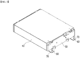
- FIG. 2 is a view illustrating the battery module illustrated as a comparative example.
- FIG. 3 is a view illustrating an interference due to the cooling port when assembling the end plate formed in FIG. 2 .
- FIG. 4 is a view illustrating a state in which the end plate of FIG.3 is assembled away from the cooling port.
- FIG. 8 is a view illustrating a state in which the end plate is assembled according to an embodiment of the present disclosure.
- FIG. 9 is a view illustrating a state in which a cooling port is assembled according to an embodiment of the present disclosure.
- FIG. 10 is a view illustrating a state in which the cooling port of FIG. 9 is assembled, as viewed from the side.
- a battery module according to a comparative example of the present disclosure may include a module frame 40 for housing the battery cell stack, end plates 50 for covering front and rear surfaces of the battery cell stack, a module frame protrusion part 60 protruded and formed from the bottom part of the module frame 40, and a cooling port 70 formed at an upper surface part of the module frame protrusion part 60.
- the cooling port 70 is coupled to the module frame protrusion part 60 during manufacture of the module frame 40 to thereby assemble the end plate 50 in a state in which a module frame assembly is formed.
- the end plate 50 when the end plate 50 is assembled in a direction that is perpendicular to an attached surface of the end plate, an interference may occur during assembling due to the cooling port 70 protruded upwards from the module frame protrusion part 60. Accordingly, in order to assemble the end plate 50, as illustrated in FIG.
- the end plate 50 is moved in a lower side direction in which the module frame protrusion part 60 is located, while vertically standing towards a space between the cooling port 70 and the module frame 40, and then is again moved in a direction which is perpendicular to the attached surface of the end plate to thereby assemble the end plate 50.
- the method for manufacturing a battery module sequentially performs a step of coupling the end plate 400 to the front and rear ends of the module frame 200 in which the battery cell stack is housed ( FIG. 8 ), and a step of coupling the cooling port on the module frame protrusion part 211 ( FIGS. 9 and 10 ). That is, by coupling the end plate 400 to the module frame 200 first, and then coupling the coupling the cooling port 500 to the module frame protrusion part 211, the assembling process of the end plate 400 can be simplified and the difficulty of assembly can be improved.
- the end plate 400 is moved along the first direction, which is the assembling direction shown in FIG. 8 , then the end plate 400 is coupled with the module frame 200, the end plate 400 is coupled to the module frame 200, then the cooling port is moved along the second direction, which is the assembling direction shown in FIG. 10 intersecting with the first direction, and then connected to the module frame protrusion part 211.
- the first direction may be a direction vertically directing to a surface that forms the edges of the module frame 200 coupled to the end plate 400.
- the end plate 400 may be coupled by welding to the edges of the module frame 200.
- the second direction may be a direction vertically directing to the upper surface of the module frame protrusion part 211.
- the step of coupling the cooling port 500 and the bracket 520 with the module frame protrusion 211 by a fastening member may include a step of aligning a first coupling hole 512 formed on both sides of the lower end of the cooling port 500, a second coupling hole 522 formed on both sides of the bracket 520, and a third coupling hole 211b formed on both sides of the module frame protrusion part 211, and a step of inserting a bolt 540 so as to penetrate the first coupling hole 512, the second coupling hole 522, and the third coupling hole 211b.
- a step of aligning the refrigerant tube 511 with the bracket connection port 521 may be further included.
- a step of inserting the gasket 530 between the cooling port 500 and the bracket 520 may be further included.
- the cooling port 500 and the bracket 520 may be connected through the assembling process disclosed in these steps.
- the cooling port 500 can move downward to be connected to the upper surface of the module frame protrusion part 211.
- the cooling port 500 and the module frame protrusion part 211 may be coupled so that the bracket connection port 521 formed on the cooling port 500 aligns with the heat sink connector 211a formed on the upper surface of the module frame protrusion part 211.
- the above-mentioned battery module can be included in the battery pack.
- the battery pack may have a structure in which one or more of the battery modules according to this embodiment are gathered, and packed together with a battery management system (BMS) and a cooling device that control and manage battery's temperature, voltage, etc.
- BMS battery management system
- the battery pack can be applied to various devices. These devices may be applied to transportation means such as an electric bicycle, an electric vehicle, a hybrid vehicle, but the present disclosure is not limited thereto and can be applied to various devices that can use the battery module, which also falls under the scope of the present disclosure.
Landscapes
- Chemical & Material Sciences (AREA)
- Chemical Kinetics & Catalysis (AREA)
- Electrochemistry (AREA)
- General Chemical & Material Sciences (AREA)
- Engineering & Computer Science (AREA)
- Manufacturing & Machinery (AREA)
- Life Sciences & Earth Sciences (AREA)
- Biophysics (AREA)
- Secondary Cells (AREA)
- Battery Mounting, Suspending (AREA)
Abstract
Description
- This application claims the benefit of
Korean Patent Application No. 10-2020-0044876 filed on April 13, 2020 - The present disclosure relates to a battery module and a method for manufacturing the same, and more particularly to a battery module having a cooling structure, and a method for manufacturing the same.
- A secondary battery has attracted much attention as an energy source in various products such as a mobile device and an electric vehicle. The secondary battery is a potent energy resource that can replace the use of existing products using fossil fuels, and is in the spotlight as an environment-friendly energy source because it does not generate by-products due to energy use.
- Recently, along with a continuous rise of the necessity for a large-capacity secondary battery structure, including the utilization of the secondary battery as an energy storage source, there is a growing demand for a battery pack of a multi-module structure which is an assembly of battery modules in which a plurality of secondary batteries are connected in series/parallel.
- Meanwhile, when a plurality of battery cells are connected in series/parallel to configure a battery pack, it is common to configure a battery module composed of battery cells first, and then configure a battery pack by using at least one of the battery modules and adding other components.
- Such a battery module includes a battery cell stack in which a plurality of battery cells are stacked, a module frame for housing the battery cell stack, and a heat sink for cooling the plurality of battery cells.
-
FIG. 1 is a view illustrating a battery module coupled to a heat sink according to the related art. - Referring to
FIG. 1 , a conventional battery module includes a battery cell stack in which a plurality ofbattery cells 10 are stacked, a module frame for housing the battery cell stack, and a thermallyconductive resin layer 15 located between thebottom part 20 of the module frame and the battery cell stack. Such a battery module can be formed under thebottom part 20 of the module frame and coupled with aheat sink 30 that provides a cooling function to a plurality ofbattery cells 10, thereby forming a battery pack. At this time, theheat sink 30 includes an inlet through which refrigerant flows in, an outlet through which refrigerant flows out, alower plate 31 having a cooling flow path for connecting the inlet and the outlet, and anupper plate 29 for covering thelower plate 31. Here, a heatconductive layer 18 may be further formed between thebottom part 20 of the battery module and theheat sink 30. - Conventionally, in order to improve the cooling performance of the battery module and/or the battery pack, a separate cooling structure, for example, a
heat sink 30, is required for each battery pack unit. Therefore, the cooling structure tended to be complicated, and the space between the refrigerant and thebattery cell laminate 10 was formed by a multi-layered structure consisting of anupper plate 29, a moduleframe bottom part 29, and the like, whereby there was a limit that it has no choice but to cool the battery cells indirectly. - It is an object of the present disclosure to provide a battery module having improved assembling property of the cooling structure to improve cooling performance, and a method for manufacturing the same.
- The objects of the present disclosure are not limited to the aforementioned objects, and other objects which are not described herein should be clearly understood by those skilled in the art from the following detailed description.
- According to one embodiment of the present disclosure, there is provided a battery module comprising: a battery cell stack in which a plurality of battery cells are stacked; a module frame for housing the battery cell stack; end plates for covering front and rear surfaces of the battery cell stack; a heat sink formed on a bottom part of the module frame; and a cooling port configured to supply a refrigerant to the heat sink, wherein the module frame comprises a module frame protrusion part, which is extended and formed so as to pass through the end plates on the bottom part of the module frame, and wherein the cooling port is disposed in a shape protruding upward from an upper surface of the module frame protrusion part.
- The cooling port may be coupled to the module frame protrusion part by a fastening member.
- The battery module may further include a bracket located between the cooling port and the upper surface of the module frame protrusion part, and the cooling port may be connected to the bracket and the module frame protrusion part by a fastening member.
- The battery module may further include a gasket formed between the cooling port and the bracket.
- First coupling holes may be formed on both sides of the lower end of the cooling port, second coupling holes may be formed on both sides of the bracket, third coupling holes may be formed on both sides of the module frame protrusion part, and the fastening member may be inserted so as to penetrate the first coupling hole, the second coupling hole, and the third coupling hole to couple the cooling port and the bracket.
- A refrigerant tube may be formed in the center of the cooling port, and the refrigerant tube may be connected to a heat sink connection port formed on the module frame protrusion part.
- A bracket connection port may be formed in the center of the bracket, the bracket connection port may be formed between the coolant tube and the heat sink connection port, thereby connecting the coolant tube and the heat sink connection port.
- The gasket may be formed in an annular shape, and maybe located between the refrigerant tube and the bracket connection port to seal between the refrigerant tube and the bracket connection port.
- The battery module may further include a heat sink protrusion part formed so as to correspond to the module frame protrusion part.
- According to another embodiment of the present disclosure, there is provided a battery pack comprising the battery module.
- According to yet another embodiment of the present disclosure, there is provided a method for manufacturing a battery module, the method comprising the steps of: coupling end plates to the front and rear ends of a module frame in which a battery cell stack is housed; and coupling a cooling port on a module frame protrusion part, with the module frame protrusion part being extended and formed so as to pass through the end plates on the bottom part of the module frame, wherein the step of coupling the end plate to the module frame comprises moving the end plates along a first direction and then coupling the end plates to the module frame, and after the end plates are coupled to the module frame, the cooling port is moved along a second direction intersecting with the first direction, and then connected to the module frame protrusion part.
- The method for manufacturing a battery module may further include a step of coupling the cooling port and a bracket located at the lower end of the cooling port to the module frame protrusion part by a fastening member.
- The step of coupling the cooling port and the bracket to the module frame protrusion part by a fastening member may include a step of aligning a first coupling hole formed on both sides of the lower end of the cooling port, a second coupling hole formed on both sides of the bracket, and a third coupling hole formed on both sides of the module frame protrusion part; and a step of inserting a bolt so as to penetrate the first coupling hole, the second coupling hole, and the third coupling hole.
- The step of coupling the cooling port and the bracket to the module frame protrusion part by a fastening member may further include a step of inserting a gasket between the cooling port and the bracket.
- In the step of coupling the end plate to the module frame, the first direction may be a direction vertically directing to a surface that forms an edge of the module frame coupled to the end plate.
- In the step of coupling the end plate to the module frame, the second direction may be a direction vertically directing to an upper surface of the module frame protrusion part.
- According to the embodiments of the present disclosure, since there is no assembly feature interference between the cooling port and the end plate, the assembling process of the end plate can be simplified and the difficulty of assembly can be improved.
- The effects of the present disclosure are not limited to the effects mentioned above and additional other effects not described above will be clearly understood from the description of the appended claims by those skilled in the art.
-
-
FIG. 1 is a view illustrating a battery module coupled to a heat sink according to the related art. -
FIG. 2 is a view illustrating a battery module illustrated as a comparative example; -
FIG. 3 is a view illustrating an interference due to a cooling port when assembling an end plate formed inFIG. 2 . -
FIG. 4 is a view illustrating a state in which the end plate ofFIG.3 is assembled away from the cooling port. -
FIG. 5 is an exploded perspective view of a battery module according to an embodiment of the present disclosure. -
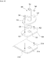
FIG. 6 is an exploded perspective view of a cooling port coupled to a battery module according to an embodiment of the present disclosure. -
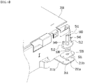
FIG. 7 is a side view illustrating a state in which the cooling port is coupled to a battery module according to the embodiment of the present disclosure. -
FIG. 8 is a view illustrating a state in which the end plate is assembled according to an embodiment of the present disclosure. -
FIG. 9 is a view illustrating a state in which a cooling port is assembled according to an embodiment of the present disclosure. -
FIG. 10 is a view illustrating a state in which the cooling port ofFIG. 9 is assembled, as viewed from the side. - It should be appreciated that the exemplary embodiments, which will be described below, are illustratively described to help understand the present disclosure, and the present disclosure may be variously modified to be carried out differently from the exemplary embodiments described herein. However, in the description of the present disclosure, the specific descriptions and illustrations of publicly known functions or constituent elements will be omitted when it is determined that the specific descriptions and illustrations may unnecessarily obscure the subject matter of the present disclosure. In addition, in order to help understand the present disclosure, the accompanying drawings are not illustrated based on actual scales, but parts of the constituent elements may be exaggerated in size.
- As used herein, terms such as first, second, and the like may be used to describe various components, and the components are not limited by the terms. The terms are used only to discriminate one component from another component.
- Further, the terms used herein are used only to describe specific exemplary embodiments, and are not intended to limit the scope of the present disclosure. A singular expression includes a plural expression unless they have definitely opposite meanings in the context. It should be understood that the terms "comprise", "include", and "have" as used herein are intended to designate the presence of stated features, numbers, steps, constitutional elements, movements, parts or combinations thereof, but it should be understood that they do not preclude a possibility of existence or addition of one or more other features, numbers, steps, movements, constitutional elements, parts or combinations thereof.
- Hereinafter, a battery module to which a cooling port is coupled according to an embodiment of the present disclosure will be described with reference to
FIGS. 5 to 7 . -
FIG. 5 is an exploded perspective view of a battery module according to an embodiment of the present disclosure.FIG. 6 is an exploded perspective view of a cooling port coupled to a battery module according to an embodiment of the present disclosure.FIG. 7 is a side view illustrating a state in which the cooling port is coupled to a battery module according to the embodiment of the present disclosure. - Referring to
FIGS. 5 to 7 , a battery module according to an embodiment of the present disclosure includes abattery cell stack 100 in which a plurality of battery cells are stacked, amodule frame 200 for housing thebattery cell stack 100,end plates 400 for covering front and rear surfaces of thebattery cell stack 100, aheat sink 300 formed on a bottom part of themodule frame 200, and acooling port 500 for supplying a refrigerant to theheat sink 300. - Referring to
FIG. 6 , the battery module according to the embodiment of the disclosure may be configured such that aheat sink 300 and a bottom portion of themodule frame 200 are integrally formed, and acooling port 500 is connected to one end of theheat sink 300. Themodule frame 200 includes a moduleframe protrusion part 211 which is extended and formed so as to pass through theend plates 400 on the bottom part of themodule frame 200, and thecooling port 500 is connected to the upper surface of the module frame protrusion part, so that a refrigerant is supplied to theheat sink 300 via the moduleframe protrusion part 211. - At this time, a
bracket 520 may be disposed between the coolingport 500 and the moduleframe protrusion part 211. The coolingport 500 may be connected to thebracket 520 by a fastening member. In this case, agasket 530 may be disposed between the coolingport 500 and thebracket 520. As a modified example, thebracket 520 may be omitted, and thecooling port 500 may be directly connected to theprotrusion part 211 described later by a fastening member. - A battery cell according to the embodiment of the disclosure is a secondary battery, which may be configured of a pouch type secondary battery. The battery cell may be formed of a plurality of cells, and the plurality of battery cells may be stacked so as to be electrically connected to each other, thereby forming the
battery cell stack 100. Each of the plurality of the battery cells may include an electrode assembly, a cell case, and an electrode lead protruding from the electrode assembly. - The
module frame 200 houses thebattery cell stack 100. According to an embodiment of the present disclosure, themodule frame 200 may include alower frame 210 for covering a lower surface and both side surfaces of thebattery cell stack 100, and anupper plate 220 for covering an upper surface of the battery cell stack100. Themodule frame 200 includes amodule frame protrusion 211, which is extended and formed so as to passe through the end plates on the bottom part of themodule frame 200. The coolingport 500 described above may be seated on an upper side of the moduleframe protrusion part 211. - However, a structure of the
module frame 200 is not limited thereto, and may be a mono frame shape surrounding four surfaces excluding the front and rear surfaces of thebattery cell stack 100. - The battery module according to the embodiment of the disclosure may further include
end plates 400 for covering the front and rear surfaces of thebattery cell stack 100. Through the above-mentionedmodule frame 200, thebattery cell stack 100 housed inside the frame may be physically protected. - Referring to
FIG. 5 , aheat sink 300 may be formed at a lower part of themodule frame 200. Theheat sink 300 may include alower plate 310 that forms a skeleton of theheat sink 300 and makes contact with the bottom part of themodule frame 200, aninlet 320 that is formed on one side of theheat sink 300 to supply a refrigerant from the outside to the interior of theheat sink 300, anoutlet 330 that is formed on one side of the heat sink and allows a refrigerant flowed inside the heat sink to be discharged to the outside of the heat sink, and aflow passage part 340 that connects theinlet 320 and theoutlet 330 and allows the refrigerant to flow. - In detail, the
flow passage part 340 may indicate a structure in which thelower plate 310 making contact with a lower surface of alower frame 210 corresponding to the bottom part of themodule frame 200 is formed to be recessed on a lower side. An upper side of theflow passage part 340 is opened, whereby a flow path is formed between theflow passage part 340 and the bottom part of themodule frame 200, and thus the refrigerant can flow through the flow path. That is, the battery module according to the embodiment of the disclosure may have an integrated type cooling structure, in which the bottom part of themodule frame 200 functions to correspond to the upper plate of theheat sink 300. - Conventionally, a structure in which the refrigerant flows is separately formed on a lower side of the module frame, so that it has no choice but to cool the module frame indirectly and thus, the cooling efficiency is deteriorated. In addition, there was a problem that a separate refrigerant flow structure is formed, which reduces the space utilization of the battery module and the battery pack on which the battery module is mounted. However, according to the embodiment of the present disclosure, the structure in which the
heat sink 300 is integrated at a lower part of themodule frame 200 can be employed so as to allow the refrigerant to directly flow between theflow passage part 340 and the bottom part of themodule frame 200, thereby increasing the cooling efficiency due to direct cooling. Moreover, through the structure in which theheat sink 300 is integrated with the bottom part of themodule frame 200, the space utilization of the battery module and the battery pack on which the battery module is mounted can be further increased. - The
lower plate 310 may be formed so as to correspond to the bottom part of themodule frame 200. The bottom part of themodule frame 200 may correspond to the bottom part of thelower frame 210, thelower plate 310 and the bottom part of thelower frame 210 can be coupled to each other through welding, and a rigidity of the entire battery module can be reinforced through thelower plate 310. Thelower plate 310 and the bottom part of thelower frame 210 are sealed through welding, whereby the refrigerant can flow without leakage in theflow passage part 340 formed inside thelower plate 310. - Both the
inlet 320 and theoutlet 330 may be formed on one side of theheat sink 300. In more detail, both theinlet 320 and theoutlet 330 may be formed on one side of theheat sink 300 that is formed at a portion at which theend plate 400 is located. Theinlet 320 and theoutlet 330 may be located at both ends of one side of theheat sink 300, respectively. Theinlet 320 and theoutlet 330 may be formed at locations corresponding to the moduleframe protrusion parts 211 so as to be connected to lower surface parts of the moduleframe protrusion parts 211. For this purpose, theinlet 320 and theoutlet 330 may be formed on the heatsink protrusion part 300P protruding from one side of theheat sink 300 to a portion where the moduleframe protrusion part 211 is located. - The
flow passage part 340 may be formed so as to cover the bottom part of themodule frame 200 while being bent. Theflow passage part 340 is formed in most of areas of the bottom part of themodule frame 200 excluding a portion in which thelower plate 310 makes contact with the bottom part of themodule frame 200, whereby all the portions of thebattery cell stack 100, which are disposed so as to occupy most of areas of the bottom part of themodule frame 200, can be uniformly cooled. - The portion at which the
flow passage part 340 is bent may be formed of a curved surface. Accordingly, the portion at which a partition wall 350 is bent may also be formed of a curved surface. When angled edge portions are formed in theflow passage part 340, it is likely that a flow of the refrigerant will stagnate at the angled edge portions, thus increasing a temperature deviation and a pressure drop. In this regard, if the bending part is treated with curved surfaces as in the embodiment of the present disclosure, the flow of the refrigerant can be made naturally. - The cooling
port 500 is connected to the upper surface of the moduleframe protrusion part 211 so that the refrigerant is supplied to theheat sink 300 through the moduleframe protrusion part 211. In more detail, as shown inFIG. 6 , a heatsink connection port 211a is formed in the moduleframe protrusion part 211, and a heatsink connection port 211a is formed on the lower surface of the moduleframe protrusion part 211 and is connected to theinlet 320 and theoutlet 330 connected to theheat sink 300, and the refrigerant supplied through thecooling port 500 may be passed through the heatsink connection port 211a and flown into the inside of the heat sink via theinlet 320. The refrigerant flown out from the inside of theheat sink 300 via anoutlet 330 can pass through the heatsink connection port 211a to be discharged to thecooling port 500 via theoutlet 330. - Referring to
FIG. 6 again, arefrigerant tube 511 may be formed in the center of thecooling port 500. The refrigerant may flow in and out through the refrigerant tube 511and then through the heatsink connection port 211a, theinlet 320 and theoutlet 330. First coupling holes 512 may be formed at both end lower sides of thecooling port 500. The coolingport 500 and thebracket 520 may be coupled to each other through thefirst coupling hole 512. The coolingport 500 may be coupled to thebracket 520 located at the lower side. Thebracket 520 is disposed between the coolingport 500 and the moduleframe protrusion part 211, and functions as a connecting member so that thecooling port 500 can be bound onto the moduleframe protrusion part 211. However, in the absence of thebracket 520, the coolingport 500 may be directly coupled to the moduleframe protrusion part 211. Thebracket 520 may include abracket connection port 521 formed at the center and second coupling holes 522 formed on both sides of thebracket connection ports 521. - The
bracket connection port 521 can be disposed between arefrigerant tube 511 and a heatsink connection port 211a to connect therefrigerant tube 511 and the heatsink connection port 211a. Therefore, the refrigerant that has passed through therefrigerant tube 511 can pass through thebracket connection port 521 and the heatsink connection port 211a in this order to be flown into theinlet 320, and the refrigerant flown out through theoutlet 330 can pass through the heatsink connection port 211a, thebracket connection port 521, and therefrigerant tube 511 in this order to be discharged to the outside. - The second coupling holes 522 may be formed on both sides of the
bracket connection port 521.Third coupling holes 211b may be formed on both sides of the upper surface of the moduleframe protrusion part 211. Thesecond coupling hole 522 and thethird coupling hole 211b are formed at positions corresponding to the first coupling holes 512 formed on both lower sides of thecooling port 500, and abolt 540 is inserted so as pass through the first coupling holes 512, the second coupling holes 522 and the third coupling holes 211b to firmly couple thecooling port 500, thebracket 520, and the moduleframe protrusion port 211. - The
gasket 530 is formed in an annular shape, and may be disposed between the coolingport 500 and thebracket 520. In more detail, thegasket 530 is disposed between therefrigerant tube 511 and thebracket connection port 521 and seals between therefrigerant tube 511 and thebracket connection port 521, thereby preventing the refrigerant from leaking between the cooling port body part 510 and thebracket 520. In addition, thegasket 530 may be formed of a rubber material to obtain flexibility of the cooling port body part 510 connected to thegasket 530. - Hereinafter, referring to
FIGS. 5 to 7 andFIGS. 8 to 10 , a method for manufacturing a battery module to which a cooling port is coupled according to an embodiment of the present disclosure will be described in comparison with a comparative example illustrated inFIGS. 2 to 4 . -
FIG. 2 is a view illustrating the battery module illustrated as a comparative example.FIG. 3 is a view illustrating an interference due to the cooling port when assembling the end plate formed inFIG. 2 .FIG. 4 is a view illustrating a state in which the end plate ofFIG.3 is assembled away from the cooling port.FIG. 8 is a view illustrating a state in which the end plate is assembled according to an embodiment of the present disclosure.FIG. 9 is a view illustrating a state in which a cooling port is assembled according to an embodiment of the present disclosure.FIG. 10 is a view illustrating a state in which the cooling port ofFIG. 9 is assembled, as viewed from the side. - Referring to
FIGS. 2 to 4 , a battery module according to a comparative example of the present disclosure may include amodule frame 40 for housing the battery cell stack,end plates 50 for covering front and rear surfaces of the battery cell stack, a moduleframe protrusion part 60 protruded and formed from the bottom part of themodule frame 40, and a coolingport 70 formed at an upper surface part of the moduleframe protrusion part 60. - Conventionally, the cooling
port 70 is coupled to the moduleframe protrusion part 60 during manufacture of themodule frame 40 to thereby assemble theend plate 50 in a state in which a module frame assembly is formed. Here, as illustrated inFIG. 3 , when theend plate 50 is assembled in a direction that is perpendicular to an attached surface of the end plate, an interference may occur during assembling due to the coolingport 70 protruded upwards from the moduleframe protrusion part 60. Accordingly, in order to assemble theend plate 50, as illustrated inFIG. 4 , theend plate 50 is moved in a lower side direction in which the moduleframe protrusion part 60 is located, while vertically standing towards a space between the coolingport 70 and themodule frame 40, and then is again moved in a direction which is perpendicular to the attached surface of the end plate to thereby assemble theend plate 50. - As illustrated in
FIG. 4 , because theend plate 50 has to be assembled through two steps, there was problem that an assembly process becomes complicated and high transfer precision is required to couple theend plate 50 with the edge portions of themodule frame 40. - Thus, the method for manufacturing a battery module according to an embodiment of the present disclosure sequentially performs a step of coupling the
end plate 400 to the front and rear ends of themodule frame 200 in which the battery cell stack is housed (FIG. 8 ), and a step of coupling the cooling port on the module frame protrusion part 211 (FIGS. 9 and10 ). That is, by coupling theend plate 400 to themodule frame 200 first, and then coupling the coupling thecooling port 500 to the moduleframe protrusion part 211, the assembling process of theend plate 400 can be simplified and the difficulty of assembly can be improved. - In the step of coupling the
end plate 400 to the front and rear ends of themodule frame 200, theend plate 400 is moved along the first direction, which is the assembling direction shown inFIG. 8 , then theend plate 400 is coupled with themodule frame 200, theend plate 400 is coupled to themodule frame 200, then the cooling port is moved along the second direction, which is the assembling direction shown inFIG. 10 intersecting with the first direction, and then connected to the moduleframe protrusion part 211. - In this case, the first direction may be a direction vertically directing to a surface that forms the edges of the
module frame 200 coupled to theend plate 400. Theend plate 400 may be coupled by welding to the edges of themodule frame 200. The second direction may be a direction vertically directing to the upper surface of the moduleframe protrusion part 211. - The step of coupling the
cooling port 500 and thebracket 520 with themodule frame protrusion 211 by a fastening member may include a step of aligning afirst coupling hole 512 formed on both sides of the lower end of thecooling port 500, asecond coupling hole 522 formed on both sides of thebracket 520, and athird coupling hole 211b formed on both sides of the moduleframe protrusion part 211, and a step of inserting abolt 540 so as to penetrate thefirst coupling hole 512, thesecond coupling hole 522, and thethird coupling hole 211b. - In the step of aligning the
first coupling hole 512 and thesecond coupling hole 522 formed on both sides of thebracket 520, a step of aligning therefrigerant tube 511 with thebracket connection port 521 may be further included. - In the step of coupling the
cooling port 500 to thebracket 520, a step of inserting thegasket 530 between the coolingport 500 and thebracket 520 may be further included. The coolingport 500 and thebracket 520 may be connected through the assembling process disclosed in these steps. - In the step of connecting the
cooling port 500 to the moduleframe protrusion port 211, the coolingport 500 can move downward to be connected to the upper surface of the moduleframe protrusion part 211. At this time, the coolingport 500 and the moduleframe protrusion part 211 may be coupled so that thebracket connection port 521 formed on thecooling port 500 aligns with theheat sink connector 211a formed on the upper surface of the moduleframe protrusion part 211. - The above-mentioned battery module can be included in the battery pack. The battery pack may have a structure in which one or more of the battery modules according to this embodiment are gathered, and packed together with a battery management system (BMS) and a cooling device that control and manage battery's temperature, voltage, etc.
- The battery pack can be applied to various devices. These devices may be applied to transportation means such as an electric bicycle, an electric vehicle, a hybrid vehicle, but the present disclosure is not limited thereto and can be applied to various devices that can use the battery module, which also falls under the scope of the present disclosure.
- Although the preferred embodiments of the present disclosure have been illustrated and described, the present disclosure is not limited to the above-described particular embodiments, various modifications can be made by those skilled in the art without departing from the scope and spirit as disclosed in the accompanying claims, and these modifications should not be understood separately from the scope and spirit of the invention.
-
- 200: module frame
- 210: lower frame
- 211: module frame protrusion part
- 211a: heat sink connection port
- 220: upper plate
- 300: heat sink
- 400: end plate
- 500: cooling port
- 510: cooling port body part
- 511: refrigerant tube
- 512: first coupling hole
- 520: bracket
- 521: bracket connection port
- 522: second coupling hole
- 530: gasket
- 540: bolt
Claims (16)
- A battery module comprising:a battery cell stack in which a plurality of battery cells are stacked;a module frame for housing the battery cell stack;end plates for covering front and rear surfaces of the battery cell stack;a heat sink formed on a bottom part of the module frame; anda cooling port configured to supply a refrigerant to the heat sink,wherein the module frame comprises a module frame protrusion part, which is extended and formed so as to pass through the end plates on the bottom part of the module frame, andwherein the cooling port is disposed in a shape protruding upward from an upper surface of the module frame protrusion part.
- The battery module according to claim 1,
wherein the cooling port is coupled to the module frame protrusion part by a fastening member. - The battery module according to claim 1,
which further comprises a bracket located between the cooling port and the upper surface of the module frame protrusion part. - The battery module according to claim 3,
which further comprises a gasket formed between the cooling port and the bracket. - The battery module according to claim 4,wherein first coupling holes are formed on both sides of the lower end of the cooling port, second coupling holes are formed on both sides of the bracket, third coupling holes are formed on both sides of the module frame protrusion part, andthe fastening member is inserted so as to penetrate the first coupling hole, the second coupling hole, and the third coupling hole to couple the cooling port and the bracket.
- The battery module according to claim 4,
wherein a refrigerant tube is formed in the center of the cooling port, and the refrigerant tube is connected to a heat sink connection port formed on the module frame protrusion part. - The battery module according to claim 6,
wherein a bracket connection port is formed in the center of the bracket, the bracket connection port is formed between the coolant tube and the heat sink connection port, thereby connecting the coolant tube and the heat sink connection port. - The battery module according to claim 7,
wherein the gasket is formed in an annular shape, and is located between the refrigerant tube and the bracket connection port to seal between the refrigerant tube and the bracket connection port. - The battery module according to claim 1,
which further comprises a heat sink protrusion part formed so as to correspond to the module frame protrusion part. - A method for manufacturing a battery module, the method comprising the steps of:coupling end plates to the front and rear ends of a module frame in which a battery cell stack is housed; andcoupling a cooling port on a module frame protrusion part, with the module frame protrusion part being extended and formed so as to pass through the end plates on the bottom part of the module frame,wherein the step of coupling the end plate to the module frame comprises moving the end plates along a first direction and then coupling the end plates to the module frame, andafter the end plates are coupled to the module frame, the cooling port is moved along a second direction intersecting with the first direction, and then connected to the module frame protrusion part.
- The method for manufacturing a battery module according to claim 10,
which further comprises a step of coupling the cooling port and a bracket located at the lower end of the cooling port to the module frame protrusion part by a fastening member. - The method for manufacturing a battery module according to claim 11,wherein the step of coupling the cooling port and the bracket to the module frame protrusion part by a fastening member comprises,a step of aligning a first coupling hole formed on both sides of the lower end of the cooling port, a second coupling hole formed on both sides of the bracket, and a third coupling hole formed on both sides of the module frame protrusion part; anda step of inserting a bolt so as to penetrate the first coupling hole, the second coupling hole, and the third coupling hole.
- The method for manufacturing a battery module according to claim 11,
wherein the step of coupling the cooling port and the bracket to the module frame protrusion part by a fastening member further comprises a step of inserting a gasket between the cooling port and the bracket. - The method for manufacturing a battery module according to claim 10,
wherein in the step of coupling the end plate to the module frame, the first direction is a direction vertically directing to a surface that forms an edge of the module frame coupled to the end plate. - The method for manufacturing a battery module according to claim 10,
wherein the second direction is a direction perpendicular to an upper surface of the module frame protrusion part. - A battery pack comprising the battery module according to claim 1.
Applications Claiming Priority (2)
| Application Number | Priority Date | Filing Date | Title |
|---|---|---|---|
| KR1020200044876A KR102950794B1 (en) | 2020-04-13 | 2020-04-13 | Battery module and manufacturing method thereof |
| PCT/KR2021/001481 WO2021210769A1 (en) | 2020-04-13 | 2021-02-04 | Battery module and manufacturing method therefor |
Publications (2)
| Publication Number | Publication Date |
|---|---|
| EP4020669A1 true EP4020669A1 (en) | 2022-06-29 |
| EP4020669A4 EP4020669A4 (en) | 2023-05-03 |
Family
ID=78083658
Family Applications (1)
| Application Number | Title | Priority Date | Filing Date |
|---|---|---|---|
| EP21788116.8A Pending EP4020669A4 (en) | 2020-04-13 | 2021-02-04 | BATTERY MODULE AND METHOD OF MANUFACTURING IT |
Country Status (6)
| Country | Link |
|---|---|
| US (1) | US20230216105A1 (en) |
| EP (1) | EP4020669A4 (en) |
| JP (1) | JP7507852B2 (en) |
| KR (1) | KR102950794B1 (en) |
| CN (1) | CN114556668A (en) |
| WO (1) | WO2021210769A1 (en) |
Families Citing this family (2)
| Publication number | Priority date | Publication date | Assignee | Title |
|---|---|---|---|---|
| CN120239926A (en) * | 2023-01-06 | 2025-07-01 | 宁德时代新能源科技股份有限公司 | Batteries and vehicles |
| EP4648193A1 (en) * | 2023-01-06 | 2025-11-12 | Contemporary Amperex Technology (Hong Kong) Limited | Battery and electrical device |
Family Cites Families (18)
| Publication number | Priority date | Publication date | Assignee | Title |
|---|---|---|---|---|
| JP4507453B2 (en) * | 2001-05-17 | 2010-07-21 | トヨタ自動車株式会社 | Fuel cell manifold |
| KR101044022B1 (en) * | 2009-03-16 | 2011-06-23 | 주원테크 주식회사 | Support structure |
| DE102011084660B4 (en) * | 2011-10-18 | 2018-02-15 | Bayerische Motoren Werke Aktiengesellschaft | Device for power supply |
| EP2860807B1 (en) * | 2013-03-26 | 2016-09-14 | Panasonic Intellectual Property Management Co., Ltd. | Fuel cell stack |
| JP2014216298A (en) | 2013-04-30 | 2014-11-17 | 日立オートモティブシステムズ株式会社 | Battery module |
| KR20150000016U (en) * | 2013-06-24 | 2015-01-02 | 현대중공업 주식회사 | Fixture for duct installation detector |
| US9627724B2 (en) * | 2014-12-04 | 2017-04-18 | Lg Chem, Ltd. | Battery pack having a cooling plate assembly |
| KR101990590B1 (en) * | 2015-08-17 | 2019-06-18 | 주식회사 엘지화학 | Battery module, battery pack comprising the battery module and vehicle comprising the battery pack |
| US11217814B2 (en) * | 2015-10-06 | 2022-01-04 | Honda Motor Co., Ltd. | Fuel battery stack |
| KR102179681B1 (en) * | 2016-01-12 | 2020-11-17 | 주식회사 엘지화학 | Battery Pack Having Side Cooling Type Cooling Member |
| US10594004B2 (en) * | 2016-12-12 | 2020-03-17 | Lg Chem, Ltd. | Battery pack |
| KR102065099B1 (en) * | 2017-04-04 | 2020-01-10 | 주식회사 엘지화학 | Battery Pack having crash beam and drain structure |
| DE102017109708A1 (en) | 2017-05-05 | 2018-11-08 | Benteler Automobiltechnik Gmbh | Cooling arrangement, fluid collector for a cooling arrangement and method for producing a fluid collector |
| JP6969913B2 (en) | 2017-06-26 | 2021-11-24 | 株式会社東芝 | Battery device |
| CN109994798B (en) * | 2017-12-26 | 2025-08-15 | Sk新能源株式会社 | Battery module and method for manufacturing same |
| KR102277035B1 (en) * | 2018-03-21 | 2021-07-13 | 주식회사 엘지에너지솔루션 | Battery module, battery pack comprising the battery module and vehicle comprising the battery pack |
| JP6997673B2 (en) | 2018-05-09 | 2022-01-17 | 本田技研工業株式会社 | Battery pack |
| DE102018212626A1 (en) * | 2018-07-27 | 2020-01-30 | Mahle International Gmbh | accumulator |
-
2020
- 2020-04-13 KR KR1020200044876A patent/KR102950794B1/en active Active
-
2021
- 2021-02-04 WO PCT/KR2021/001481 patent/WO2021210769A1/en not_active Ceased
- 2021-02-04 JP JP2022519035A patent/JP7507852B2/en active Active
- 2021-02-04 CN CN202180005839.2A patent/CN114556668A/en active Pending
- 2021-02-04 US US17/769,514 patent/US20230216105A1/en active Pending
- 2021-02-04 EP EP21788116.8A patent/EP4020669A4/en active Pending
Also Published As
| Publication number | Publication date |
|---|---|
| KR20210127027A (en) | 2021-10-21 |
| CN114556668A (en) | 2022-05-27 |
| JP7507852B2 (en) | 2024-06-28 |
| WO2021210769A1 (en) | 2021-10-21 |
| EP4020669A4 (en) | 2023-05-03 |
| JP2022550523A (en) | 2022-12-02 |
| KR102950794B1 (en) | 2026-04-08 |
| US20230216105A1 (en) | 2023-07-06 |
Similar Documents
| Publication | Publication Date | Title |
|---|---|---|
| US20220285759A1 (en) | Battery Module and Battery Pack Including the Same | |
| US20220407143A1 (en) | Battery module, battery pack and vehicle including the same | |
| US12407042B2 (en) | Battery module and battery pack including the same | |
| US12525678B2 (en) | Battery module and battery pack including the same | |
| EP4016702A1 (en) | Battery module and battery pack including same | |
| EP4016704B1 (en) | Battery pack and device including the same | |
| CN116472637A (en) | Battery pack and device including the battery pack | |
| US20230402678A1 (en) | Battery Pack and Device Including the Same | |
| EP4020669A1 (en) | Battery module and manufacturing method therefor | |
| US20230216149A1 (en) | Battery Module and Manufacturing Method Thereof | |
| US20220247011A1 (en) | Battery module and manufacturing method thereof | |
| US12283679B2 (en) | Battery module and battery pack including the same | |
| US12206082B2 (en) | Battery module and manufacturing method thereof | |
| EP4550530A1 (en) | Battery module and battery pack comprising same | |
| US20250219189A1 (en) | Battery Pack with Improved Cooling Structure and Device Including the Same |
Legal Events
| Date | Code | Title | Description |
|---|---|---|---|
| STAA | Information on the status of an ep patent application or granted ep patent |
Free format text: STATUS: THE INTERNATIONAL PUBLICATION HAS BEEN MADE |
|
| PUAI | Public reference made under article 153(3) epc to a published international application that has entered the european phase |
Free format text: ORIGINAL CODE: 0009012 |
|
| STAA | Information on the status of an ep patent application or granted ep patent |
Free format text: STATUS: REQUEST FOR EXAMINATION WAS MADE |
|
| 17P | Request for examination filed |
Effective date: 20220323 |
|
| AK | Designated contracting states |
Kind code of ref document: A1 Designated state(s): AL AT BE BG CH CY CZ DE DK EE ES FI FR GB GR HR HU IE IS IT LI LT LU LV MC MK MT NL NO PL PT RO RS SE SI SK SM TR |
|
| A4 | Supplementary search report drawn up and despatched |
Effective date: 20230330 |
|
| RIC1 | Information provided on ipc code assigned before grant |
Ipc: H01M 50/20 20210101ALI20230324BHEP Ipc: H01M 10/613 20140101ALI20230324BHEP Ipc: H01M 10/6556 20140101ALI20230324BHEP Ipc: H01M 10/6551 20140101AFI20230324BHEP |
|
| DAV | Request for validation of the european patent (deleted) | ||
| DAX | Request for extension of the european patent (deleted) |