EP4020334A1 - Appareils, systèmes et procédés pour pièges à objets atomiques elliptiques - Google Patents
Appareils, systèmes et procédés pour pièges à objets atomiques elliptiques Download PDFInfo
- Publication number
- EP4020334A1 EP4020334A1 EP21215443.9A EP21215443A EP4020334A1 EP 4020334 A1 EP4020334 A1 EP 4020334A1 EP 21215443 A EP21215443 A EP 21215443A EP 4020334 A1 EP4020334 A1 EP 4020334A1
- Authority
- EP
- European Patent Office
- Prior art keywords
- electrodes
- atomic object
- atomic
- electrode
- object trap
- Prior art date
- Legal status (The legal status is an assumption and is not a legal conclusion. Google has not performed a legal analysis and makes no representation as to the accuracy of the status listed.)
- Pending
Links
- 238000000034 method Methods 0.000 title abstract description 19
- 238000004891 communication Methods 0.000 claims description 24
- 238000001816 cooling Methods 0.000 claims description 23
- 230000009471 action Effects 0.000 claims description 17
- 239000013078 crystal Substances 0.000 claims description 10
- 239000002096 quantum dot Substances 0.000 claims description 10
- 230000000087 stabilizing effect Effects 0.000 claims description 7
- 230000002889 sympathetic effect Effects 0.000 claims description 6
- 150000002500 ions Chemical class 0.000 description 12
- 238000012545 processing Methods 0.000 description 10
- 239000003989 dielectric material Substances 0.000 description 7
- 230000005684 electric field Effects 0.000 description 6
- 230000004907 flux Effects 0.000 description 6
- 230000005540 biological transmission Effects 0.000 description 5
- 239000011810 insulating material Substances 0.000 description 5
- 238000010586 diagram Methods 0.000 description 4
- 230000006870 function Effects 0.000 description 4
- 238000005040 ion trap Methods 0.000 description 4
- 230000003287 optical effect Effects 0.000 description 4
- 230000008569 process Effects 0.000 description 4
- 239000000758 substrate Substances 0.000 description 4
- 238000012546 transfer Methods 0.000 description 4
- 238000004590 computer program Methods 0.000 description 3
- 230000001419 dependent effect Effects 0.000 description 3
- 230000003993 interaction Effects 0.000 description 3
- 238000004519 manufacturing process Methods 0.000 description 3
- RYGMFSIKBFXOCR-UHFFFAOYSA-N Copper Chemical compound [Cu] RYGMFSIKBFXOCR-UHFFFAOYSA-N 0.000 description 2
- VYPSYNLAJGMNEJ-UHFFFAOYSA-N Silicium dioxide Chemical compound O=[Si]=O VYPSYNLAJGMNEJ-UHFFFAOYSA-N 0.000 description 2
- 238000003491 array Methods 0.000 description 2
- 125000004429 atom Chemical group 0.000 description 2
- 230000008901 benefit Effects 0.000 description 2
- 230000001413 cellular effect Effects 0.000 description 2
- 239000004020 conductor Substances 0.000 description 2
- 229910052802 copper Inorganic materials 0.000 description 2
- 239000010949 copper Substances 0.000 description 2
- 230000000694 effects Effects 0.000 description 2
- 238000005516 engineering process Methods 0.000 description 2
- 230000007613 environmental effect Effects 0.000 description 2
- 230000033001 locomotion Effects 0.000 description 2
- 238000012986 modification Methods 0.000 description 2
- 230000004048 modification Effects 0.000 description 2
- 230000007935 neutral effect Effects 0.000 description 2
- 230000011664 signaling Effects 0.000 description 2
- 230000000007 visual effect Effects 0.000 description 2
- BQCADISMDOOEFD-UHFFFAOYSA-N Silver Chemical compound [Ag] BQCADISMDOOEFD-UHFFFAOYSA-N 0.000 description 1
- 229910045601 alloy Inorganic materials 0.000 description 1
- 239000000956 alloy Substances 0.000 description 1
- 238000004422 calculation algorithm Methods 0.000 description 1
- 230000007812 deficiency Effects 0.000 description 1
- 238000001514 detection method Methods 0.000 description 1
- 230000005672 electromagnetic field Effects 0.000 description 1
- 238000001125 extrusion Methods 0.000 description 1
- 239000000835 fiber Substances 0.000 description 1
- PCHJSUWPFVWCPO-UHFFFAOYSA-N gold Chemical compound [Au] PCHJSUWPFVWCPO-UHFFFAOYSA-N 0.000 description 1
- 229910052737 gold Inorganic materials 0.000 description 1
- 239000010931 gold Substances 0.000 description 1
- 230000005283 ground state Effects 0.000 description 1
- 239000012212 insulator Substances 0.000 description 1
- 238000000960 laser cooling Methods 0.000 description 1
- 230000007774 longterm Effects 0.000 description 1
- 238000004949 mass spectrometry Methods 0.000 description 1
- 239000000463 material Substances 0.000 description 1
- 238000005259 measurement Methods 0.000 description 1
- 230000005055 memory storage Effects 0.000 description 1
- 238000010295 mobile communication Methods 0.000 description 1
- 230000003647 oxidation Effects 0.000 description 1
- 238000007254 oxidation reaction Methods 0.000 description 1
- 238000004812 paul trap Methods 0.000 description 1
- 230000008707 rearrangement Effects 0.000 description 1
- 230000009467 reduction Effects 0.000 description 1
- 238000011160 research Methods 0.000 description 1
- 238000013515 script Methods 0.000 description 1
- 235000012239 silicon dioxide Nutrition 0.000 description 1
- 239000000377 silicon dioxide Substances 0.000 description 1
- 229910052709 silver Inorganic materials 0.000 description 1
- 239000004332 silver Substances 0.000 description 1
- 230000006641 stabilisation Effects 0.000 description 1
- 238000011105 stabilization Methods 0.000 description 1
Images


Classifications
-
- G—PHYSICS
- G06—COMPUTING; CALCULATING OR COUNTING
- G06N—COMPUTING ARRANGEMENTS BASED ON SPECIFIC COMPUTATIONAL MODELS
- G06N10/00—Quantum computing, i.e. information processing based on quantum-mechanical phenomena
- G06N10/40—Physical realisations or architectures of quantum processors or components for manipulating qubits, e.g. qubit coupling or qubit control
-
- H—ELECTRICITY
- H01—ELECTRIC ELEMENTS
- H01J—ELECTRIC DISCHARGE TUBES OR DISCHARGE LAMPS
- H01J49/00—Particle spectrometers or separator tubes
- H01J49/26—Mass spectrometers or separator tubes
- H01J49/34—Dynamic spectrometers
- H01J49/42—Stability-of-path spectrometers, e.g. monopole, quadrupole, multipole, farvitrons
- H01J49/4205—Device types
- H01J49/422—Two-dimensional RF ion traps
-
- G—PHYSICS
- G06—COMPUTING; CALCULATING OR COUNTING
- G06N—COMPUTING ARRANGEMENTS BASED ON SPECIFIC COMPUTATIONAL MODELS
- G06N10/00—Quantum computing, i.e. information processing based on quantum-mechanical phenomena
-
- G—PHYSICS
- G06—COMPUTING; CALCULATING OR COUNTING
- G06N—COMPUTING ARRANGEMENTS BASED ON SPECIFIC COMPUTATIONAL MODELS
- G06N10/00—Quantum computing, i.e. information processing based on quantum-mechanical phenomena
- G06N10/20—Models of quantum computing, e.g. quantum circuits or universal quantum computers
Definitions
- Various embodiments relate to apparatuses, systems, and methods for atomic object traps.
- An atomic object trap can use electrical fields to capture one or more atomic object in a potential well.
- Atomic objects can be trapped for a number of purposes, which may include mass spectrometry, research, and/or controlling quantum states thereof, for example.
- Trapped atomic objects, such as trapped ions can encode information in their quantum states and act as qubits in quantum computing.
- Example embodiments provide atomic object traps, atomic object trap apparatuses, quantum computers comprising atomic object trap apparatuses, quantum computer systems comprising atomic object trap apparatuses, and/or the like.
- the atomic objects are atoms, ions, ion crystals, and/or the like.
- an ion crystal is a group of atoms and/or ions (e.g., an ion pair comprising a qubit atomic object and a sympathetic cooling atomic object).
- the provided embodiments are optimized to support simultaneous trapping of a relatively large number of atomic objects with a relatively small number of electrical signals.
- an atomic object trap apparatus is substantially elliptically-shaped and has increased compactness and electrical connectivity.
- the elliptical shape of an atomic object trap apparatus enables laser beams, electrical leads, and/or the like to be shared among different and spatially separated zones and/or electrodes.
- an atomic object trap apparatus comprises two or more radio frequency (RF) electrodes formed concentrically in a substantially elliptical shape, and three or more trapping and/or transport (TT) electrode sequences formed concentrically each in a substantially elliptical shape.
- the two or more RF electrodes and the three or more TT electrode sequences define a substantially elliptically-shaped atomic object trap.
- At least one TT electrode sequence is disposed concentrically between the two or more RF electrodes.
- Each substantially elliptically-shaped RF electrode and TT electrode sequence comprises two substantially parallel longitudinal regions and two arc-spanning beltway regions.
- each substantially parallel longitudinal region of each of the three or more TT electrode sequences is arranged into a plurality of zones and each arc-spanning beltway region of the at least one TT electrode sequence disposed concentrically between the two or more RF electrodes comprises a plurality of TT electrodes arranged into three or more subgroups of TT electrodes.
- the TT electrodes of each of the three or more subgroups of TT electrodes are in electrical communication with each other.
- the plurality of TT electrodes is arranged such that every n th TT electrode is associated with one subgroup of TT electrodes, wherein n is greater than 1.
- each subgroup of TT electrodes is configured to be operated independently to at least one of (a) create a plurality of potential wells, or (b) move a potential well.
- creating a plurality of potential wells and moving a potential well are configured to cause at least an atomic object within the defined atomic object trap to be transported from a first longitudinal region of a RF electrode to a second longitudinal region of the RF electrode via one of the two arc-spanning beltway regions.
- the at least an atomic object comprises an ion-crystal.
- the ion-crystal comprises a qubit atomic object and a sympathetic cooling (SC) atomic object.
- the plurality of zones comprises a plurality of gating zones and a plurality of auxiliary zones.
- each gating zone is disposed between two auxiliary zones, the gating zone configured for an action to be performed on at least one atomic object within the gating zone (e.g., via application of one or more electromagnetic fields) and the auxiliary zones are configured for stabilizing the at least one atomic object during a transport operation of the at least one atomic object.
- stabilizing the at least one atomic object comprises maintaining the at least one atomic object such that the quantum information/data stored and/or encoded by the qubit atomic object is not disturbed or lost.
- the performed action comprises at least one of (a) a split operation, (b) a combine operation, or (c) a swap operation, the action being caused at least in part by a manipulation source.
- the manipulation source is a laser beam, the laser beam being configured to act as a manipulation source for one or more gating zones.
- each gating zone of the at least one TT electrode sequence disposed concentrically between the two or more RF electrodes comprises at least five TT electrodes.
- each auxiliary zone of the at least one electrode sequence disposed concentrically between the two or more RF electrodes comprises at least three TT electrodes.
- At least one of the two arc-spanning beltway regions of the at least one TT electrode sequence disposed concentrically between the two or more RF electrodes comprises a load hole configured for loading atomic objects into the ion trap.
- the two or more RF electrodes are disposed between a first and third sequence of TT electrodes
- the two or more RF electrodes form at least one elliptical gap
- a second sequence of TT electrodes is disposed within the elliptical gap.
- the ion trap apparatus is part of a trapped atomic object quantum computer.
- an atomic object trap apparatus comprises a plurality of elliptically-shaped radio frequency (RF) electrodes, and a plurality of elliptically-shaped trapping and/or transport (TT) electrode sequences.
- the plurality of RF electrodes and the plurality of TT electrode sequences define an ion trap.
- the defined atomic object trap comprises a longitudinal gating region and two beltway regions.
- the longitudinal gating region is arranged into a plurality of zones and the two beltway regions are configured to be operated so as to cause an atomic object within the atomic object trap to be transported from a first zone of the plurality of zones to a second zone of the plurality of zones.
- each of the two beltway regions comprises a plurality of TT electrodes disposed between the RF electrodes, the plurality of TT electrodes being energized to generate a plurality of electrical potentials.
- the plurality of TT electrodes are arranged into three or more subgroups of TT electrodes.
- the TT electrodes of each subgroup of TT electrodes are in electrical communication with each other and energized together.
- the plurality of TT electrodes is arranged such that every n th TT electrode is associated with one subgroup of TT electrodes, wherein n is greater than 1.
- each subgroup of TT electrodes is configured to be operated independently to at least one of (a) create a plurality of potential wells, or (b) move a potential well.
- the generated potential wells may be dynamic.
- creating a plurality of potential wells and moving a potential well are configured to cause at least an atomic object within the defined atomic object trap to be transported from a first longitudinal region of a RF electrode to a second longitudinal region of the RF electrode.
- the at least an atomic object comprises an ion-crystal.
- the ion-crystal comprises a qubit atomic object and a sympathetic cooling (SC) atomic object.
- the plurality of zones comprises a plurality of gating zones and a plurality of auxiliary zones.
- each gating zone is disposed between two auxiliary zones, the gating zone configured for an action to be performed on at least one atomic object within the gating zone and the auxiliary zones configured for stabilizing the at least one atomic object during a transport operation of the at least one atomic object.
- the performed action comprises at least one of (a) a split operation, (b) a combine operation, or (c) a swap operation, the action being caused at least in part by a manipulation source.
- the manipulation source is a laser beam.
- the laser beam is configured to act as a manipulation source for one or more gating zones.
- at least one of the two beltway regions of the defined atomic object trap comprises a load hole configured for loading atomic objects into the atomic object trap.
- the atomic object trap apparatus is part of a trapped atomic object quantum computer.
- TT electrode sequence is substantially elliptically-shaped and disposed between two substantially elliptically-shaped radio frequency (RF) electrodes.
- RF radio frequency
- the method further comprises cooling the plurality of atomic objects using a cooling laser beam; detecting an amount of fluorescence emitted by the plurality of atomic objects (e.g., responsive to and/or emitted as part of the cooling of the atomic objects); and transporting the plurality of atomic objects.
- the transporting generates at least one electrical potential configured to cause loading of a second plurality of atomic objects through the load hole.
- an apparatus comprising means for loading a plurality of atomic objects through a load hole located at an arc-spanning beltway region of a trapping and/or transport (TT) electrode sequence, wherein the TT electrode sequence is substantially elliptically-shaped and disposed between two substantially elliptically-shaped radio frequency (RF) electrodes.
- TT electrode sequence is substantially elliptically-shaped and disposed between two substantially elliptically-shaped radio frequency (RF) electrodes.
- RF radio frequency
- Each substantially elliptically-shaped TT electrode sequence and RF electrode comprises two substantially parallel longitudinal regions and two arc-spanning beltway regions.
- the apparatus comprises means for cooling the plurality of atomic objects.
- the apparatus comprises means for detecting an amount of fluorescence emitted by the plurality of atomic objects as part of the cooling process.
- the apparatus comprises means for transporting the plurality of atomic objects. The transporting generates at least one electrical potential configured to cause loading of a second plurality of atomic objects through the load hole.
- Figure 1 provides a schematic diagram of an example quantum computer system 100 comprising an atomic object trap apparatus and/or package 50, in accordance with an example embodiment.
- the atomic object trap apparatus and/or package 50 of the quantum computer system 100 may comprise an elliptical atomic object trap according to the embodiments provided in the present disclosure.
- the quantum computer system 100 comprises a computing entity 10 and a quantum computer 110.
- the quantum computer 110 comprises a controller 30, a cryostat and/or vacuum chamber 40 enclosing an atomic object trap apparatus and/or package 50, and one or more manipulation sources 60.
- the one or more manipulation sources 60 may comprise one or more lasers (e.g., optical lasers, microwave sources, and/or the like).
- the one or more manipulation sources 60 are configured to manipulate and/or cause a controlled quantum state evolution of one or more atomic objects within an atomic object trap of the atomic object trap apparatus and/or package 50.
- the lasers may provide one or more laser beams 66 to the atomic object trap of the atomic object trap apparatus and/or package 50 within the cryogenic and/or vacuum chamber 40.
- the quantum computer 110 comprises one or more voltage sources 55.
- the voltage sources 55 may comprise a plurality of voltage drivers and/or voltage sources and/or at least one RF driver and/or voltage source. The voltage sources 55 may be electrically coupled to corresponding electrodes of the atomic object trap apparatus and/or package 50 via corresponding leads.
- a computing entity 10 is configured to allow a user to provide input to the quantum computer 110 (e.g., via a user interface of the computing entity 10) and receive, view, and/or the like output from the quantum computer 110.
- the computing entity 10 may be in communication with the controller 30 of the quantum computer 110 via one or more wired or wireless networks 20 and/or via direct wired and/or wireless communications.
- the computing entity 10 may translate, configure, format, and/or the like information/data, quantum computing algorithms, and/or the like into a computing language, executable instructions, command sets, and/or the like that the controller 30 can understand, execute, process, and/or implement.
- the computing entity 10 may translate, configure, format, and/or the like information/data, commands, quantum computation results, and/or quantum information provided by the controller 30 into information/data that the computing entity 10 can understand, execute, process, and/or implement.
- the controller 30 is configured to control the voltage sources 55, cryogenic system and/or vacuum system controlling the temperature and pressure within the cryogenic and/or vacuum chamber 40, manipulation sources 60, and/or other systems controlling various environmental conditions (e.g., temperature, pressure, and/or the like) within the cryogenic and/or vacuum chamber 40 and/or configured to manipulate and/or cause a controlled evolution of quantum states of one or more atomic objects within the atomic object trap of the atomic object trap apparatus and/or package 50.
- the atomic objects trapped within the atomic object trap of the atomic object trap apparatus and/or package 50 are used as qubits of the quantum computer 110.
- the manipulation sources 60 comprise lasers and laser beams 66A-C delivered to the atomic object trap apparatus and/or package 50. It will be understood that laser beams 66A-C are illustrated for informative purposes and are not limiting as to indicate that the manipulation sources may only comprise three laser beams.
- the manipulation sources 60 comprise a plurality of lasers and laser beams.
- the manipulation sources 60 are configured to be provided to one or more zones and/or regions of an elliptical atomic object trap of the atomic object trap apparatus and/or package 50.
- the manipulation sources 60 may comprise a laser beam 66A which may be provided to one zone of the elliptical atomic object trap and another spatially separated zone of the elliptical atomic object trap.
- the voltage sources 55 may comprise a plurality of voltage drivers and/or voltage sources and/or at least one RF driver and/or voltage source.
- One or more voltage drivers and/or voltage sources may be configured to operate and/or be connected to more than one electrode of an elliptical atomic object trap of the atomic object trap apparatus and/or package 50.
- one voltage driver and/or voltage source of the voltage sources 55 may be configured to operate a subgroup of electrodes of the elliptical atomic object trap.
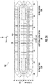
- Figure 2A provides a top or plan view of an elliptical atomic object trap 200 of an atomic object trap apparatus and/or package 50 according to an example embodiment.
- the atomic object trap 200 is generally and/or substantially elliptical in shape with the major axis of the ellipse defining a longitudinal axis 205 of the atomic object trap 200.
- the elliptical atomic object trap 200 is configured to trap (e.g., via electric fields) a plurality of atomic objects.
- atomic objects may be atoms, ions, ion crystals, and/or the like.
- an ion crystal is a group of atoms and/or ions comprising and/or consisting of a qubit atom and/or ion and at least one sympathetic cooling (SC) atom and/or ion.
- the atomic object trap apparatus and/or package 50 may comprise an atomic object trap chip and/or a substrate on which the elliptical atomic object trap 200 is defined or fabricated.
- the elliptical atomic object trap 200 is a surface atomic object trap.
- the elliptical atomic object trap 200 may be a surface Paul trap. As shown in Figure 2A , the elliptical atomic object trap 200 is substantially elliptically-shaped.
- the elliptical atomic object trap 200 comprises a longitudinal gating region 210 and two arc-spanning beltway regions 220A-B, the three regions together forming a substantially elliptical shape.
- the longitudinal gating region 210 may be longitudinal along a longitudinal axis 205 of the elliptical atomic object trap 200.
- the elliptical atomic object trap 200 may comprise two or more radio frequency (RF) electrodes.
- RF radio frequency
- the top view of the elliptical atomic object trap 200 provided in Figure 2A illustrates the elliptical atomic object trap 200 comprising two radio frequency (RF) electrodes formed concentrically in a substantially elliptical shape.
- the elliptical atomic object trap 200 comprises an outer RF electrode 230 and an inner RF electrode 240.
- the elliptical atomic object trap 20 may comprise a plurality of RF electrodes.
- the RF electrodes 230, 240 may be substantially parallel to one another and/or to the longitudinal axis 205.
- Each RF electrode 230, 240 may be substantially elliptically-shaped.
- Figure 2A illustrates the outer RF electrode 230 comprising two substantially parallel longitudinal regions and two arc-spanning beltway regions. Specifically, the two substantially parallel longitudinal regions are located within the longitudinal gating region 210 of the elliptical atomic object trap 200, and each arc-spanning beltway region is located in a beltway region 220A or 220B of the elliptical atomic object trap 200.
- an arc-spanning beltway region of an RF electrode may refer to a portion of the RF electrode that is located within a beltway region 220 of the elliptical atomic object trap 200
- a substantially parallel longitudinal region of an RF electrode may refer to a portion of the RF electrode that is located within the longitudinal gating region 210 of the elliptical atomic object trap 200.
- the two substantially parallel longitudinal regions may be substantially parallel to the longitudinal axis 205 of the elliptical atomic object trap 200.
- the two arc-spanning beltway regions may be substantially transverse and/or intersect the longitudinal axis 205 of the elliptical atomic object trap 200.
- the two substantially parallel longitudinal regions and the two arc-spanning beltway regions of the outer RF electrode 230 form a complete elliptical loop, thus defining the outer RF electrode 230.
- the inner RF electrode 240 may be substantially elliptically-shaped similar to the outer RF electrode 230.
- the inner RF electrode 240 also comprises two substantially parallel longitudinal regions and two arc-spanning beltway regions.
- the inner RF electrode 240 may be formed concentrically with the outer RF electrode 230. That is, the inner RF electrode 240 does not intersect with the outer RF electrode 230. Because the inner RF electrode 240 may be formed concentrically with the outer RF electrode 230, the two substantially parallel longitudinal regions of the inner RF electrode 240 and the two substantially parallel longitudinal regions of the outer RF electrode 230 may also be parallel to each other and with the longitudinal axis 205 of the elliptical atomic object trap 200.
- the two arc-spanning beltway regions of the inner RF electrode 240 and the two arc-spanning beltway regions of the outer RF electrode 230 may span the same angle and/or exhibit the same degree of concavity such that the inner RF electrode 240 and the outer RF electrode 230 are concentric, and may also be substantially transverse and/or intersect the longitudinal axis 205 of the elliptical atomic object trap 200.
- the two or more RF electrodes may be fabricated above an upper surface of an atomic object trap chip and/or a substrate of an atomic object trap apparatus and/or package 50.
- other materials e.g., dielectrics, insulators, shields, etc. can be formed between said atomic object trap chip and/or substrate and the two or more RF electrodes (and/or other elliptical atomic object trap 200 components).
- the RF electrodes 230, 240 may be fabricated from a conductive material (e.g., copper, silver, gold, and/or the like) or alloys of two or more conductive materials selected as suitable for conduction and/or transmission of an appropriate signal.
- the RF electrodes 230, 240 may be fabricated, for example, from copper.
- the cross-sectional area of the RF rails may be determined and/or modified to enable conduction of a current (e.g., from around 0.01A to around 10.0A) oscillating at an RF frequency (e.g., from around 3 Hz to 0.3 GHz).
- the radial depth of the outer and inner RF electrodes 230, 240 may be varied as suitable for particular applications.
- each RF electrode 230, 240 may be configured to have a radial depth of 80 ⁇ m each.
- the radial depth dimension may be further defined as the dimension of each electrode radial from a center of the elliptical atomic object trap 200.
- the radial depth dimension may substantially be the y-dimension in the longitudinal gating region 210 and the x-dimension at the ends of the beltway regions 220.
- a circumferential width dimension may be further defined as the dimension normal to the radial depth dimension and substantially along the length of the elliptical shape of the elliptical atomic object trap 200.
- the circumferential width dimension may substantially be the x-dimension in the longitudinal gating region 210 and the y-dimension at the ends of the beltway regions 220.
- the outer and inner RF electrodes 230, 240 may be separated (e.g., insulated) from one another by an elliptical gap.
- the elliptical gap separating the outer and inner RF electrodes 230, 240 may be configured to have a radial depth of 80 ⁇ m, i.e. there exists at least a radial distance of 80 ⁇ m between the two RF electrodes 230, 240.
- the elliptical gap may be at least partially filled with an insulating material (e.g., a dielectric material).
- the dielectric material may be silicon dioxide (e.g., formed through thermal oxidation) and/or other dielectric and/or insulating material.
- the arrangement and geometry of the RF electrodes 230, 240 may be configured to generate an elliptical trapping region located about 70 ⁇ m above the atomic object trap surface (e.g., in the positive z-direction) and above the elliptical gap between the RF electrodes 230, 240.
- the elliptical trapping region may be a three-dimensional volume above the elliptical atomic object trap 200 within which atomic objects are trapped and/or contained.
- the elliptical shape of the elliptical trapping region may be defined to coincide with, be an extrusion of, and/or be substantially the same as the elliptical gap between the RF electrodes 230, 240.
- the elliptical atomic object trap 200 may be configured to trap at least one atomic object in a portion of the elliptical trapping region.
- RF signals may be applied to the two or more RF electrodes to generate an electric and/or magnetic field that acts to maintain one or more atomic objects trapped within the elliptical trapping region. The electric and/or magnetic field may be generated in directions transverse to the elliptical length of the RF electrodes.
- the elliptical atomic object trap 200 may comprise three or more substantially elliptically-shaped transport and/or trapping (TT) electrode sequences, with at least one such TT electrode sequence being disposed between the RF electrodes.
- Figure 2A illustrates the elliptical atomic object trap 200 comprising three substantially elliptically-shaped transport and/or trapping (TT) electrode sequences: the first TT electrode sequence (also hereinafter referred to as the outer TT electrode sequence) being disposed radially outside the outer RF electrode 230, the second TT electrode sequence disposed within the elliptical gap between the RF electrodes 230, 240, and the third TT electrode sequence (also hereinafter referred to as the inner TT electrode sequence) disposed radially inside the inner RF electrode 240.
- the first TT electrode sequence also hereinafter referred to as the outer TT electrode sequence
- the second TT electrode sequence disposed within the elliptical gap between the RF electrodes 230, 240
- the elliptical atomic object trap 200 comprises a plurality of TT electrode sequences. Similar to the RF electrodes 230, 240, each TT electrode sequence may be substantially elliptically-shaped. For example, each TT electrode sequence may comprise two substantially parallel longitudinal regions and two arc-spanning beltway regions. The two substantially parallel longitudinal regions of each TT electrode sequence may be located and/or defined within the longitudinal gating region 210 of the elliptical atomic object trap 200, and each arc-spanning beltway region may be located and/or defined within a beltway region 220 of the elliptical atomic object trap 200.
- Each TT electrode sequence may also be formed to be concentric to the RF electrodes; that is, each of the elliptical atomic object trap 200 components (e.g., the RF electrodes and the TT electrode sequences) may be concentric relative to each other.
- the longitudinal regions of all the RF electrodes and TT electrode sequences may be parallel with the longitudinal axis 205 of the elliptical atomic object trap 200, and the arc-spanning beltway regions of all the RF electrodes and TT electrode sequences may span the same angle and/or exhibit the same degree of concavity and may be transverse and/or intersect with the longitudinal axis 205 of the elliptical atomic object trap 200.
- the upper surface (e.g., in the positive z-direction) of the elliptical atomic object trap 200 may have planarized topology.
- the upper surface (e.g., in the positive z-direction) of each RF electrode and each TT electrode sequence may be substantially coplanar.
- the upper surface of each RF electrode and each TT electrode sequence may also be substantially coplanar or substantially flush with the upper surface of the atomic object trap apparatus and/or package 50.
- the thicknesses (e.g., in the z-direction) of each RF electrode and each TT electrode sequence may be approximately equal.
- the thickness of the RF electrodes 230, 240 and the TT electrodes sequences is in the range of approximately 0.1-20 ⁇ m.
- the thicknesses (e.g., in the z-direction) of the outer and inner TT electrode sequences are greater than the thicknesses of the RF electrodes 230, 240 and the at least one TT electrode sequence disposed between the RF electrodes, which may have substantially the same thickness.
- the three or more TT electrode sequences may have the same or substantially similar radial depth (e.g., dimension in the x-y plane) as the RF electrodes.
- each TT electrode sequence may be configured to have a radial depth of 80 ⁇ m each.
- the at least one TT electrode sequence disposed between the RF electrodes may be configured to have a radial depth equal to or less than the radial depth of the elliptical gap separating the outer and inner RF electrodes 230, 240.
- the elliptical gap may be configured to have a radial depth of 80 ⁇ m and partially filled with insulating material, thereby resulting in the at least one TT electrode sequence disposed within being configured to have a radial depth of less than 80 ⁇ m.
- circumferential gaps may exist between neighboring or adjacent TT electrodes of each TT electrode sequence.
- each circumferential gap may be empty space and/or at least partially filled with a dielectric material to prevent electrical communication between neighboring or adjacent TT electrodes.
- each circumferential gap may be configured to be approximately 1-10 ⁇ m.
- each TT electrode sequence and a neighboring or adjacent RF electrode may be electrically insulated from each other to prevent electrical communication.
- dielectric and/or insulating material may be positioned at locations between a TT electrode sequence and a RF electrode to prevent electrical communication, such dielectric and/or insulating material having a radial depth of approximately 1-10 ⁇ m.
- TT voltages may be applied to TT electrodes of each TT electrode sequence to maintain and/or cause transport of one or more atomic objects trapped within the elliptical trapping region.
- the TT voltages in conjunction with the RF signals applied to the two or more RF electrodes may generate an electric and/or magnetic field configured to maintain and/or cause transport of one or more trapped atomic objects.
- Figure 2B illustrates a top or plan view of a portion of an example beltway region 220 of an elliptical atomic object trap, such as the beltway regions 220A-B illustrated in Figure 2A .
- Figure 2B illustrates a right-side (e.g., in the y-direction) beltway region 220, more akin to beltway region 220B illustrated in Figure 2A .
- a beltway region 220 may be configured the same and/or similarly regardless of which side of an elliptical atomic object trap it is disposed.
- the architecture illustrated and described in beltway region 220 of Figure 2B may be applicable to both beltway regions 220A and 220B of Figure 2A .
- each beltway region 220 may be configured to transport atomic objects trapped in the elliptical atomic object trap 200 from one zone to another zone.
- the elliptical atomic object trap 200 may trap an atomic object in a portion of a first substantially parallel longitudinal region of the elliptical trapping region, and the elliptical atomic object trap 200 may be configured to transport said atomic object through a beltway region 220 to another portion located in a second substantially parallel longitudinal region of the elliptical trapping region.
- a specific beltway region 220 e.g., either 220A or 220B
- the controller 30 may select beltway region 220B instead of beltway region 220A to transport the atomic object when the atomic object is originally located at and/or is to be transported to a portion located at the right end of the longitudinal gating region 210.
- Each beltway region 220 may comprise the arc-spanning beltway regions of the two or more RF electrodes and the arc-spanning beltway regions of the three or more TT electrode sequences.
- Figure 2B illustrates the arc-spanning beltway regions of the outer and inner RF electrodes 230, 240 and the arc-spanning beltway region of the second TT electrode sequence 250 disposed between the RF electrodes.
- these arc-spanning beltway regions may be concentric (e.g., span the same angle and/or exhibit the same degree of concavity), and the arc-spanning beltway region of the second TT electrode sequence 250 is disposed in the gap between the arc-spanning beltway regions of the outer and inner RF electrodes 230, 240.
- the second TT electrode sequence 250 may be at least one TT electrode sequence.
- the second TT electrode sequence 250 disposed between the RF electrodes comprises a plurality of TT electrodes.
- the second TT electrode sequence 250 comprises TT electrodes 222, 224, and 226 in one of its arc-spanning beltway regions.
- the plurality of TT electrodes of an arc-spanning beltway region of the second TT electrode sequence 250 disposed between the RF electrodes may be arranged into three or more subgroups of TT electrodes.
- Figure 2B illustrates the plurality of TT electrodes being arranged into three subgroups of TT electrodes, the subgroups being labelled "A", "B", and "C".
- subgroup A may include the TT electrodes labelled with an "A" such as TT electrode 222; subgroup B may include the TT electrodes labelled with a "B” such as TT electrode 224; subgroup C may include the TT electrodes labelled with a "C” such as TT electrode 226.
- the plurality of TT electrodes are arranged such that every third electrode belongs to the same subgroup.
- the plurality of TT electrodes may be arranged into n subgroups such that every n th electrode belongs to the same subgroup (where n is greater than 1).
- n is at least three, due to the inventors' understanding that at least three energized TT electrodes are required to create and move a single electrical potential well.
- each TT electrode of a subgroup is in electrical communication with the other TT electrodes of the same subgroup.
- a TT electrode labelled "A" belonging to subgroup A is in electrical communication with every other TT electrode also labelled "A" belonging to subgroup A.
- the TT electrodes belonging to a subgroup are electrically shorted together to allow for electrical communication with each other. Due to the electrical shorting between the TT electrodes of a subgroup, a subgroup of TT electrodes may be operated by one voltage waveform.
- a subgroup of TT electrodes may be connected and/or configured to communicate with a voltage driver and/or voltage source of the voltage sources 55 such that the one voltage driver and/or voltage source may operate the subgroup of TT electrodes.
- the number of voltage sources 55 needed to operate a beltway region may correspond to the number of subgroups.
- the three or more subgroups of TT electrodes in the beltway region 220 illustrated in Figure 2B may be operated by three or more voltage waveforms.
- the beltway region 220 illustrated in Figure 2B may be connected and/or configured to communicate with at least three voltage drivers and/or voltage sources of the voltage sources 55.
- the electrical and/or magnetic field generated at least in part by the voltages applied throughout the three or more subgroups of TT electrodes may trap at least one atomic object in one of the plurality of potential wells above the upper surface of the second TT electrode sequence 250 and/or the elliptical gap between the RF electrodes.
- the subgroups of TT electrodes may be operated to move a plurality of electrical potential wells such as to cause at least one atomic object to be transported from a zone of the elliptical trapping region in the longitudinal gating region 210 to another zone of the elliptical trapping region in the longitudinal gating region 210.
- the subgroups of TT electrodes may be operated to transport the at least one atomic object from a first substantially parallel longitudinal region of the elliptical trapping region to a second substantially parallel longitudinal region of the elliptical trapping region, the two substantially parallel longitudinal regions being portions of the elliptical trapping region located within the longitudinal gating region 210.
- the elliptical trapping region may be a three-dimensional volume above the elliptical atomic object trap 200 within which atomic objects are trapped and/or contained, and may be located above (e.g., in the positive z-direction) the TT electrode sequence 250 disposed between the RF electrodes.
- TT voltages may be raised or lowered across the three or more subgroups of TT electrodes to promote transit of at least one atomic object and/or resist further transit of the at least one atomic object.
- the beltway region 220 may also comprise a load hole 280 configured for loading atomic objects into the elliptical atomic object trap 200.
- the load hole 280 may be a through hole extending through the elliptical atomic object trap 200 and through the atomic object trap chip and/or substrate on which the elliptical atomic object trap 200 is defined to allow an atomic object source (e.g., an effusive oven) to be disposed below the atomic object trap apparatus and/or package 50 such that an atomic object from the atomic object source may travel through the load hole 280 into the beltway region 220.
- an atomic object source e.g., an effusive oven
- an atomic object may enter the beltway region 220 via the load hole 280 and be interacted with by one of the manipulation sources 60, which may ionize said atomic object such that the resulting atomic object is trapped within the elliptical atomic object trap 200.
- the beltway region 220 may be configured to receive an atomic object through the load hole 280, stabilize the atomic object within the beltway region 220, enable manipulation of the atomic object via one or more manipulation sources 60 (e.g., to initialize the atomic object and/or ensure the atomic object is in a known, initial quantum state), and/or the like.
- the loading TT electrodes 256A, 256B are TT electrodes located adjacent to the load hole 280.
- the load hole 280 may be a through hole that is disposed at least partially within the loading TT electrodes 256A, 256B.
- the loading TT electrodes 256A, 256B are independently controlled (e.g., not part of subgroup A, B, or C).
- the TT electrodes disposed on and/or neighboring either side of the loading TT electrodes 256A, 256B are both assigned to subgroup A.
- the TT electrode disposed on a first side of the loading TT electrodes may be assigned to a first subgroup (e.g., subgroup A) and the TT electrode disposed on a second side of the loading TT electrodes (e.g., adjacent to or neighboring loading TT electrode 256B) may be assigned to a different subgroup (e.g., subgroup B or C).
- the beltway region 220 may comprise the arc-spanning beltway regions of the outer TT electrode sequence and the inner TT electrode sequence, the outer TT electrode sequence being disposed radially outward from the outer RF electrode 230 and the inner TT electrode sequence being disposed radially inward from the inner RF electrode 240, as shown generally in Figure 2A .
- the outer and the inner TT electrode sequences each comprise a plurality of TT electrodes.
- one TT electrode of the outer TT electrode sequence and one TT electrode of the inner TT electrode sequence may correspond to n TT electrodes of the TT electrode sequence 250 disposed between the RF electrodes, where n is greater than 1. In an example embodiment, n is at least three.
- one outer TT electrode and one inner TT electrode may correspond to at least three TT electrodes and may be configured to assist in creating, stabilizing, and moving the single electrical potential well above the at least three TT electrodes.
- the number of outer TT electrodes and the number of inner TT electrodes that correspond to n TT electrodes may be adjusted based on the curvature of the electrodes. For example, the inner circumferential width (e.g., dimension in the x-y plane) of each TT electrode of the second TT electrode sequence 250 is less than the outer circumferential width of each TT electrode due to the curved geometry, thus the number of outer TT electrodes corresponding to at least three TT electrodes may be higher than the number of inner TT electrodes.
- the outer and inner TT electrode sequences may be operated independently of the second TT electrode sequence 250 disposed between the RF electrodes 230, 240.
- the outer and inner TT electrodes may be operated by voltage waveforms different and/or independent from the three or more voltage waveforms operating the three or more subgroups of TT electrodes disposed between the RF electrodes 230, 240.
- each outer TT electrode and inner TT electrode may be adjusted such that one outer and one inner TT electrode correspond to at least three TT electrodes of the second TT electrode sequence 250.
- the two outer TT electrodes at the end of each beltway region e.g., two outer TT electrodes at each end of the longitudinal axis 205 of the elliptical atomic object trap 200
- the width of these outer TT electrodes at least at the end of each beltway region may be reduced as illustrated to reduce interference with electrical signals being conducted through the outer and inner RF electrodes 230, 240 and/or electrical leads (e.g., in electrical communication with the RF electrodes 230, 240, and/or one or more TT electrodes) that extend under the RF and/or TT electrodes of the elliptical atomic object trap 200 (e.g., at the ends of the elliptical atomic object trap 200).
- the effect of the electric fields generated by the RF electrodes 230, 240 may extend underneath the elliptical atomic object trap 200, and a reduction of the radial dimension of these outer TT electrodes by a configurable amount may prevent and/or reduce such effect underneath the elliptical atomic object trap 200.
- the dimensions of the outer and inner TT electrodes may be determined and/or modified in order to enable electrical potentials to be generated above the corresponding at least three TT electrodes of the second TT electrode sequence 250.
- FIG. 2C an example portion of a longitudinal gating region 210 of an elliptical atomic object trap 200 is illustrated.
- the longitudinal gating region 210 may comprise the substantially parallel longitudinal regions of the two or more RF electrodes and the substantially parallel longitudinal regions of the three or more TT electrode sequences.
- the substantially parallel longitudinal regions of RF electrodes 230, 240 and the TT electrode sequences 250, 260, 270 are illustrated in Figure 2C .
- Figure 2C only provides a portion of a longitudinal gating region 210 and not a longitudinal gating region 210 in its entirety such as is shown in Figure 2A .
- the longitudinal gating region 210 may be substantially similar to, comprise of, and/or the same as a longitudinal ion trap, such as those described in co-pending U.S. Patent Application 16/717,602 , the contents of which are herein incorporated by reference.
- the longitudinal gating region 210 may be arranged into a plurality of zones. Therefore, each substantially parallel longitudinal region of the three TT electrode sequences 250, 260, 270 may also be arranged into a plurality of zones.
- Figure 2C illustrates the portion of the longitudinal gating region 210 being arranged into three zones 214A, 212A, 214B in the upper half and three zones 214C, 212B, 214D in the lower half.
- Each zone may comprise a portion of each of the two or more RF electrodes and the three or more TT electrode sequences.
- Each zone may also comprise a portion of the elliptical trapping region.
- the elliptical trapping region may be a three-dimensional volume above the elliptical atomic object trap 200 within which atomic objects are trapped and/or contained, and may be specifically located above the at least one TT electrode sequence disposed between the RF electrodes.
- an atomic object trapped in a portion of the elliptical trapping region above the portion of the second TT electrode sequence 250 in zone 212A may be considered simply to be trapped in zone 212A.
- the plurality of zones may comprise a plurality of gating zones and a plurality of auxiliary zones.
- zones 212A, 212B may be a gating zones 212A, 212B
- zones 214A, 214B, 214C, 214D may be auxiliary zones 214A, 214B, 214C, 214D.
- each gating zone may be disposed between two auxiliary zones. In other words, an atomic object may enter an auxiliary zone 214 immediately when being transported out of a gating zone 212 and prior to entering any other gating zone 212.
- each gating zone 212 may comprise a number of electrodes of the second TT electrode sequence 250 disposed between the RF electrodes. In an example embodiment, each gating zone 212 comprises five electrodes of the second TT electrode sequence 250 disposed between the RF electrodes.
- a gating zone 212 may comprise TT electrodes 252A-E, as shown in Figure 2C (TT electrodes 252B, 252C, 252D not explicitly labelled to reduce visual clutter of the drawing).
- TT electrodes 252A-E may be individually controllable.
- each TT electrode 252A-E may be connected to and/or configured to be in electrical communication with a different voltage driver and/or voltage source of the voltage sources 55.
- TT electrodes of the second TT electrode sequence 250 in the longitudinal gating region 210 differ from the TT electrodes of the second TT electrode sequence 250 in the arc-spanning beltway regions 220 because the TT electrodes in the longitudinal gating region may not be arranged into subgroups and may be individually controllable.
- TT electrodes 252A-E may each have different circumferential widths.
- TT electrodes 252A, 252E may be wide-matched electrodes, whereas TT electrodes 252B, 252C, 252D may be narrow-matched electrodes.
- each gating zone 212 may comprise a number of outer gating electrodes 262 of the outer TT electrode sequence 260 and a number of inner gating electrodes 272 of the inner TT electrode sequence 270.
- gating zone 212A of the outer TT electrode sequence 260 may comprise at least five TT electrodes
- gating zone 212A of the inner TT electrode sequence 260 may comprise at least five TT electrodes as well (e.g., outer gating electrode 262 as illustrated may be outer gating electrodes 262A-262E).
- each gating zone 212 may comprise fifteen TT electrodes from the three or more TT electrode sequences.
- the number of gating electrodes 262, 272 from the outer and inner TT electrode sequences 260, 270 belonging to a gating zone 212 may be determined, configured, and/or modified based at least in part on an action to be performed on an atomic object within the gating zone 212 or a level of control needed over the electrical potential in the gating zone 212.
- the electrodes within a gating zone 212 may be individually controllable. For example, each outer electrode 262, inner electrode 272, and electrode 252 disposed between the RF electrodes 230, 240 may be operated by a different voltage driver and/or voltage source of the voltage sources 55.
- each gating zone 212 may be configured for an action to be performed on at least one atomic object within each gating zone 212A.
- the elliptical atomic object trap 200 may be configured to trap at least one atomic object in a portion of an elliptical trapping region within gating zone 212A, where gating zone 212A may be configured to perform a specific action on the at least one atomic object.
- Example actions may include split operations (e.g., dividing two atomic objects that were in the same potential well into two distinct and/or separate potential wells), combine operations (e.g., bringing two atomic objects into the same potential well), swap operations (e.g., switching the relative positions of two or more atomic objects within the atomic object trap), and/or other functions that may enable the controlled evolution of a quantum state of at least one atomic object trapped within the elliptical atomic object trap 200 and/or the arbitrary rearrangement of one or more trapped atomic objects.
- the ability to arbitrarily arrange one or more trapped atomic objects allows for arbitrary pairs of atomic objects to be placed in each gating zone 212, which allows for quantum gate operations to be performed. Following the execution of such quantum gate operations, the atomic objects may be arbitrarily rearranged and transported out of a gating zone 212 to facilitate another operation to be performed in the same gating zone 212.
- the various actions that may be performed within gating zones 212 may be caused by a manipulation source of the manipulation sources 60.
- one manipulation source of the manipulation sources 60 may be configured to cause actions in different gating zones 212.
- a manipulation source such as laser beam 66B may be configured to cause an action to be performed in gating zone 212A and another action to be performed in gating zone 212B, due to the relative proximity of the two zones.
- a manipulation source may be configured to cause actions to be performed in two gating zones that are more spatially separated (e.g., on different ends of the longitudinal gating region 210).
- a number of manipulation sources are required to cool one or more trapped atomic objects in a gating zone 212 to near their motional ground state before quantum gate operations may be performed on the one or more trapped atomic objects.
- the manipulation sources used to cool the one or more trapped atomic objects may be different than the manipulation sources used to cause the execution of quantum gate operations.
- another number of manipulation sources may be used to generate state-dependent fluorescence from the trapped atomic objects after quantum gate operations have been performed.
- the manipulation sources used to generate state-dependent fluorescence may be different than the manipulation sources used to cause the execution of quantum gate operations and the manipulation sources used to cool the one or more trapped atomic objects.
- each auxiliary zone 214 may comprise a number of electrodes of the second TT electrode sequence 250 disposed between the RF electrodes. In an example embodiment, each auxiliary zone 214 comprises three electrodes of the TT electrode sequence 250 disposed between the RF electrodes.
- an auxiliary zone 214 may comprise TT electrodes 254A-C, as shown in Figure 2C (TT electrodes 254A, 254C not explicitly labelled to reduce visual clutter in the drawing).
- TT electrodes 254A and 254C may be wide-matched electrodes, whereas TT electrode 254B may be a narrow-matched electrode.
- Each auxiliary zone 214 may also comprise a number of outer auxiliary electrodes 264 of the outer TT electrode sequence 260 and a number of inner auxiliary electrodes 274 of the inner TT electrode sequence 270.
- auxiliary zone 214A may comprise one outer auxiliary electrode 264 from the outer TT electrode sequence 260 and one inner auxiliary electrode 274 from the inner TT electrode sequence 270.
- each auxiliary zone may comprise five TT electrodes from the three or more TT electrode sequences.
- Each TT electrode within an auxiliary zone 214 may be individually controllable.
- each of TT electrodes 254A-C, outer auxiliary electrode 264, and inner auxiliary electrode 274 of an auxiliary zone 214 may be connected to and/or configured to be in electrical communication with a different voltage driver and/or voltage source of the voltage sources 55.
- each auxiliary zone 214 may be configured for stabilizing and/or storing an atomic object therein, separating at least one atomic object from a potential well having multiple atomic objects therein into a different potential well, and for transporting the atomic object therethrough.
- an auxiliary zone 214 may be configured and/or designed to accommodate storage and/or stabilization of one or more atomic objects during various atomic object transport steps.
- electrical fields generated as a result of voltages applied to the various TT electrodes within each zone may trap at least one atomic object in a potential well above the upper surface of each zone. Furthermore, these electrical fields may be manipulated by controlling the applied voltages to then promote transit of the at least one atomic object to another zone or resist further transit of the at least one atomic object.
- the elliptical atomic object trap 200 may be operated within a cryogenic and/or vacuum chamber capable of cooling the atomic object trap to a temperature of less than 124 Kelvin (e.g., less than 100 Kelvin, less than 50 Kelvin, less than 10 Kelvin, less than 5 Kelvin, and/or the like), in various embodiments.
- 124 Kelvin e.g., less than 100 Kelvin, less than 50 Kelvin, less than 10 Kelvin, less than 5 Kelvin, and/or the like
- an elliptical atomic object trap 200 may comprise more or fewer gating zones 212, and a corresponding greater or lesser number of auxiliary zones 214 than illustrated in Figures 2A-2C .
- a variety of number of gating zones 212 and/or auxiliary zones 214 and various arrangements thereof may be used in various embodiments, as appropriate for the application.
- the elliptical atomic object trap 200 comprises eight gating zones 212 and ten auxiliary zones 214.
- Figure 3 illustrates an example method 300 for operating a quantum computer system comprising an atomic object trap apparatus and/or package.
- the method 300 may be performed to operate the quantum computer system 100 comprising the atomic object trap apparatus and/or package 50.
- the atomic object trap apparatus and/or package 50 may comprise an elliptical atomic object trap according to the example embodiments provided in the present disclosure, such as elliptical atomic object trap 200 illustrated in Figures 2A -D.
- the quantum computer system 100 may comprise means for executing and/or performing the method 300.
- the method 300 may be executed at least in part by the controller 30 and/or the computing entity 10.
- a plurality of atomic objects may be loaded through a load hole of an atomic object trap.
- the load hole may be located at an arc-spanning beltway region of a trapping and/or transport (TT) electrode sequence, such as the arc-spanning beltway region of the second TT electrode sequence 250 illustrated in Figure 2B .
- TT electrode sequence may be substantially elliptically-shaped and disposed between two substantially elliptically-shaped radio frequency (RF) electrodes, wherein each substantially elliptically-shaped TT electrode sequence and RF electrode comprises two substantially parallel longitudinal regions and two arc-spanning beltway regions.
- RF radio frequency
- the load hole 280 illustrated in Figure 2B may be an example of a load hole through which a plurality of atomic objects are loaded at block 302.
- the load hole 280 may be defined in a location in the elliptical atomic object trap 200 that minimizes perturbance of atomic objects trapped in the longitudinal gating region 210 or beltway region 220 (e.g., during a loading operation).
- the load hole 280 may be defined at the end of the beltway region 220 as illustrated in Figure 2B to minimize perturbance of atomic objects trapped in the longitudinal gating region 210.
- the elliptical atomic object trap 200 may comprise one or more load holes 280, and a load hole 280 may be selected for loading a plurality of atomic objects based on a relative distance away from the trapped atomic objects within the elliptical atomic object trap 200.
- the plurality of atomic objects may be trapped within the elliptical trapping region located above the elliptical atomic object trap 200.
- the plurality of atomic objects may be trapped in a portion of the elliptical trapping region located above the load hole 280 through which the plurality was loaded.
- loading a plurality of atomic objects through a load hole may comprise the use of an effusive oven which may provide atomic flux through the load hole.
- the effusive oven may be a part of the atomic object trap apparatus and/or package 50 and/or the quantum computing system 100.
- the effusive oven may be operated to a specific temperature and/or temperature range configured to provide a pre-determined amount of atomic flux through the load hole.
- the quantum computing system 100 and/or the atomic object trap apparatus and/or package 50 may comprise means for providing atomic flux through the load hole.
- loading a plurality of atomic objects through a load hole 280 further comprises the use of a photo-ionization laser above the load hole to convert the provided atomic flux into ionized atomic objects.
- the photo-ionization laser may be a part of the atomic object trap apparatus and/or package 50 and/or the quantum computing system 100.
- the quantum computing system 100 and/or the atomic object trap apparatus and/or package 50 may comprise various means for converting the neutral atomic flux into ionized atomic objects.
- the provided atomic flux may be electrically neutral.
- the photo-ionization laser may be one of the manipulation sources 60.
- the plurality of atomic objects may be cooled using a cooling laser beam.
- the quantum computing system 100 and/or atomic object trap apparatus and/or package 50 may comprise a cooling laser beam or means for cooling a plurality of atomic objects.
- the cooling laser beam may be configured to be operated at a specific frequency, wavelength, temperature and/or the like to cool the plurality of atomic objects to a specific pre-determined temperature, temperature range, kinetic energy, kinetic energy range, and/or the like.
- the controller 30 may operate the cooling laser beam with determined parameters to cool the plurality of atomic objects to a specific pre-determined temperature, temperature range, kinetic energy, kinetic energy range, and/or the like.
- the cooling laser beam may be one of the manipulation sources 60.
- the plurality of atomic objects may be cooled sufficiently that the atomic objects may be captured, maintained, and/or the like within one or more potential wells generated by the RF and/or TT electrodes of the atomic object trap.
- the cooling laser beam may specifically be a Doppler cooling laser beam.
- the interaction of a cooling laser beam with an atomic object may cause the atomic object to cool by fluorescing and/or luminescing (e.g., emitting one or more photons).
- an amount of fluorescence emitted by the plurality of atomic objects may be detected.
- the amount of fluorescence may be emitted as a result of the cooling of the plurality of atomic objects (see block 304).
- the amount of fluorescence emitted may be dependent on one or more of a number of atomic objects cooled, the resulting temperature and/or kinetic energy of the plurality of atomic objects, the starting temperature and/or kinetic energy (before cooling) of the plurality of atomic objects, and various parameters of the cooling laser beam or means used to cool the plurality of atomic objects.
- the quantum computing system 100 and/or the atomic object trap apparatus and/or package 50 may comprise means, such as a photo-detector (e.g., photodiode, photon multiplier tube, and/or the like), for detecting the amount of fluorescence emitted by the plurality of atomic objects.
- the controller 30 may be configured to operate such means, such as a photo-detector, and/or receive a signal therefrom and control some components and/or parameters such as an aperture or image filters.
- the fluorescence emitted by the plurality of atomic objects may specifically be Doppler fluorescence.
- the plurality of atomic objects may be transported, from one portion of the elliptical trapping region to another portion of the elliptical trapping region.
- the plurality of atomic objects may be trapped and/or contained in a portion of the elliptical trapping region substantially above and/or corresponding to the load hole 280.
- the elliptical atomic object trap 200 may (e.g., by a controller 30) raise or lower TT voltages across the three or more subgroups of TT electrodes to promote transit of the plurality of atomic objects.
- raising, lowering, or otherwise modifying voltage waveforms provided to the TT electrodes of the beltway region may move a plurality of potential wells within which the plurality of atomic objects are trapped and/or contained.
- Transporting the plurality of atomic objects may cause at least one electrical potential to be generated that is configured to cause loading of a second plurality of atomic objects through the load hole.
- the transporting may depend on the detection of an appropriate amount of fluorescence at block 306.
- block 308 may not begin or execute until a pre-determined threshold of fluorescence is detected; that is, block 306 may repeat indefinitely until such a threshold criteria is met and/or satisfied.
- the method 300 may terminate if the pre-determined threshold of fluorescence is not detected for a pre-determined amount of time.
- the plurality of atomic objects may be transported from a portion of the arc-spanning beltway region of the second TT electrode sequence to another portion of the arc-spanning beltway region of the second TT electrode sequence.
- the plurality of atomic objects may be located above (e.g., in the positive z-direction) the second TT electrode sequence 250 in the elliptical trapping region (as described above in the context of Figures 2A-D ), and may be transported from a location above one portion of the second TT electrode sequence 250 to another location above another portion of the second TT electrode sequence 250.
- a portion of the TT electrode sequence over which a plurality of atomic objects may be trapped and transported to/from may be defined by n or more TT electrodes, where n is greater than 1.
- n is at least three.
- the TT electrodes of the TT electrode sequence 250 may each belong to different subgroups, thereby allowing the creation and movement of a plurality of electrical potential wells.
- the plurality of atomic objects may be transported by operation of the TT electrodes of the TT electrode sequence 250, or more specifically, operation of each subgroup of TT electrodes.
- the arc-spanning beltway region operates like a "conveyor belt," such that the plurality of atomic objects may be transported to a neighboring portion, each portion defined by n or more TT electrodes.
- the plurality of atomic objects may be transported from the arc-spanning beltway region directly to a zone within the longitudinal gating region 210 of the elliptical atomic object trap 200.
- the transporting of the plurality of atomic objects automatically creates a new electrical potential above the load hole, causing and/or allowing loading of a second plurality of atomic objects through the load hole.
- the method 300 may be repeated for a number of times because the transporting of the plurality of atomic objects automatically may cause the loading of a second plurality of atomic objects. The method 300 may be repeated until the desired number of atomic objects are loaded into the elliptical atomic object trap.
- the second plurality of atomic objects may be a different species than the first plurality of atomic objects loaded at block 302. For example, different atomic object species may be loaded to enable sympathetic laser cooling of some atomic objects trapped in the longitudinal gating region 210.
- Various embodiments provide technical solutions to the technical problem of providing an atomic object trap apparatus that provides sufficient atomic object location control, enables various atomic object transport functions (e.g., transport atomic objects, separating two or more atomic objects within one potential well into different potential wells, swapping and/or separating two atomic objects (e.g., dividing two atomic objects that were in the same potential well into two distinct and/or separate potential wells) and/or the like), and enables manipulation of atomic objects within the atomic object trap via manipulation sources, while at the same time minimizing physical space on a chip and minimizing the amount of voltage waveforms (e.g., electrical leads) required to operate such an atomic object trap apparatus.
- various atomic object transport functions e.g., transport atomic objects, separating two or more atomic objects within one potential well into different potential wells, swapping and/or separating two atomic objects (e.g., dividing two atomic objects that were in the same potential well into two distinct and/or separate potential wells) and/or
- the novel elliptical atomic object trap architecture enables a relatively large number of trap zones (e.g., to thereby provide more qubits for a quantum computer system) with a relatively small number of electrical signals needed for operation and a relatively small physical area needed on an atomic object trap chip.
- the large number of trap zones enable the simultaneous trapping of a large number of atomic objects, thereby providing a quantum computing system with a large number of qubits.
- Figure 2A illustrates an example architecture capable of simultaneously trapping over 50 separate atomic objects.
- the presently described elliptical atomic object trap architecture is further enabled for improved micro-fabrication as compared to micro-fabrication of prior atomic object traps.
- an atomic object trap apparatus and/or package 50 is incorporated into a quantum computer 110.
- a quantum computer 110 further comprises a controller 30 configured to control various elements of the quantum computer 110.
- the controller 30 may be configured to control the voltage sources 55, a cryogenic system and/or vacuum system controlling the temperature and pressure within the cryogenic and/or vacuum chamber 40, manipulation sources 60, and/or other systems controlling the environmental conditions (e.g., temperature, humidity, pressure, and/or the like) within the cryogenic and/or vacuum chamber 40 and/or configured to manipulate and/or cause a controlled evolution of quantum states of one or more atomic objects within an elliptical atomic object trap of the atomic object trap apparatus and/or package 50.
- the controller 30 may comprise various controller elements including processing elements 405, memory 410, driver controller elements 415, a communication interface 420, analog-digital converter elements 425, and/or the like.
- the processing elements 405 may comprise programmable logic devices (CPLDs), microprocessors, coprocessing entities, application-specific instruction-set processors (ASIPs), integrated circuits, application specific integrated circuits (ASICs), field programmable gate arrays (FPGAs), programmable logic arrays (PLAs), hardware accelerators, other processing devices and/or circuitry, and/or the like.
- the term circuitry may refer to an entirely hardware embodiment or a combination of hardware and computer program products.
- the processing element 405 of the controller 30 comprises a clock and/or is in communication with a clock.
- the memory 410 may comprise non-transitory memory such as volatile and/or non-volatile memory storage such as one or more of as hard disks, ROM, PROM, EPROM, EEPROM, flash memory, MMCs, SD memory cards, Memory Sticks, CBRAM, PRAM, FeRAM, RRAM, SONOS, racetrack memory, RAM, DRAM, SRAM, FPM DRAM, EDO DRAM, SDRAM, DDR SDRAM, DDR2 SDRAM, DDR3 SDRAM, RDRAM, RIMM, DIMM, SIMM, VRAM, cache memory, register memory, and/or the like.
- volatile and/or non-volatile memory storage such as one or more of as hard disks, ROM, PROM, EPROM, EEPROM, flash memory, MMCs, SD memory cards, Memory Sticks, CBRAM, PRAM, FeRAM, RRAM, SONOS, racetrack memory, RAM, DRAM, SRAM, FPM DRAM, EDO DRAM, SDRAM, DDR SDRAM, DDR2
- the memory 410 may store qubit records corresponding the qubits of quantum computer (e.g., in a qubit record data store, qubit record database, qubit record table, and/or the like), a calibration table, an executable queue, computer program code (e.g., in a one or more computer languages, specialized controller language(s), and/or the like), and/or the like.
- qubit records corresponding the qubits of quantum computer (e.g., in a qubit record data store, qubit record database, qubit record table, and/or the like), a calibration table, an executable queue, computer program code (e.g., in a one or more computer languages, specialized controller language(s), and/or the like), and/or the like.
- execution of at least a portion of the computer program code stored in the memory 410 causes the controller 30 to perform one or more steps, operations, processes, procedures and/or the like described herein for tracking the phase of an atomic object within an atomic system and causing the adjustment of the phase of one or more manipulation sources and/or signal(s) generated thereby.
- the driver controller elements 415 may include one or more drivers and/or controller elements each configured to control one or more drivers.
- the driver controller elements 415 may comprise drivers and/or driver controllers.
- the driver controllers may be configured to cause one or more corresponding drivers to be operated in accordance with executable instructions, commands, and/or the like scheduled and executed by the controller 30 (e.g., by the processing element 405).
- the driver controller elements 415 may enable the controller 30 to operate a manipulation source 60.
- the drivers may be laser drivers; vacuum component drivers; drivers for controlling the flow of current and/or voltage applied to TT, RF, and/or other electrodes used for maintaining and/or controlling the atomic object trapping potential of an elliptical atomic object trap 200; cryogenic and/or vacuum system component drivers; and/or the like.
- the drivers may control and/or comprise TT and/or RF voltage drivers and/or voltage sources that provide voltages and/or electrical signals to the TT electrodes and/or RF electrodes via a plurality of leads.
- the controller 30 comprises means for communicating and/or receiving signals from one or more optical receiver components such as cameras, MEMs cameras, CCD cameras, photodetectors, photodiodes, photomultiplier tubes, and/or the like.
- the controller 30 may comprise one or more analog-digital converter elements 425 configured to receive signals from one or more optical receiver components, calibration sensors, and/or the like.
- the controller 30 may comprise a communication interface 420 for interfacing and/or communicating with a computing entity 10.
- the controller 30 may comprise a communication interface 420 for receiving executable instructions, command sets, and/or the like from the computing entity 10 and providing output received from the quantum computer 110 (e.g., from an optical collection system) and/or the result of a processing the output to the computing entity 10.
- the computing entity 10 and the controller 30 may communicate via a direct wired and/or wireless connection and/or one or more wired and/or wireless networks 20.
- a computing entity 10 is illustrated.
- the example computing entity may be used in conjunction with embodiments of the present invention.
- a computing entity 10 is configured to allow a user to provide input to the quantum computer system 100 (e.g., via a user interface of the user computing entity 10) and receive, view, and/or the like output from the quantum computer system 100.
- a computing entity 10 can include an antenna 512, a transmitter 504 (e.g., radio), a receiver 506 (e.g., radio), and a processing element 508 that provides signals to and receives signals from the transmitter 504 and receiver 506, respectively.
- the signals provided to and received from the transmitter 704 and the receiver 706, respectively, may include signaling information/data in accordance with an air interface standard of applicable wireless systems to communicate with various entities, such as a controller 30, other computing entities 10, and/or the like.
- the computing entity 10 may be capable of operating with one or more air interface standards, communication protocols, modulation types, and access types.
- the computing entity 10 may be configured to receive and/or provide communications using a wired data transmission protocol, such as fiber distributed data interface (FDDI), digital subscriber line (DSL), Ethernet, asynchronous transfer mode (ATM), frame relay, data over cable service interface specification (DOCSIS), or any other wired transmission protocol.
- a wired data transmission protocol such as fiber distributed data interface (FDDI), digital subscriber line (DSL), Ethernet, asynchronous transfer mode (ATM), frame relay, data over cable service interface specification (DOCSIS), or any other wired transmission protocol.
- FDDI fiber distributed data interface
- DSL digital subscriber line
- Ethernet asynchronous transfer mode
- ATM asynchronous transfer mode
- frame relay frame relay
- DOCSIS data over cable service interface specification
- the computing entity 10 may be configured to communicate via wireless external communication networks using any of a variety of protocols, such as general packet radio service (GPRS), Universal Mobile Telecommunications System (UMTS), Code Division Multiple Access 2000 (CDMA2000), CDMA2000 1X (1xRTT), Wideband Code Division Multiple Access (WCDMA), Global System for Mobile Communications (GSM), Enhanced Data rates for GSM Evolution (EDGE), Time Division-Synchronous Code Division Multiple Access (TD-SCDMA), Long Term Evolution (LTE), Evolved Universal Terrestrial Radio Access Network (E-UTRAN), Evolution-Data Optimized (EVDO), High Speed Packet Access (HSPA), High-Speed Downlink Packet Access (HSDPA), IEEE 802.11 (Wi-Fi), Wi-Fi Direct, 802.16 (WiMAX), ultra wideband (UWB), infrared (IR) protocols, near field communication (NFC) protocols, Wibree, Bluetooth protocols, wireless universal serial bus (USB) protocols, and/or any other wireless protocol.
- GPRS general
- the computing entity 10 may use such protocols and standards to communicate using Border Gateway Protocol (BGP), Dynamic Host Configuration Protocol (DHCP), Domain Name System (DNS), File Transfer Protocol (FTP), Hypertext Transfer Protocol (HTTP), HTTP over TLS/SSL/Secure, Internet Message Access Protocol (IMAP), Network Time Protocol (NTP), Simple Mail Transfer Protocol (SMTP), Telnet, Transport Layer Security (TLS), Secure Sockets Layer (SSL), Internet Protocol (IP), Transmission Control Protocol (TCP), User Datagram Protocol (UDP), Datagram Congestion Control Protocol (DCCP), Stream Control Transmission Protocol (SCTP), HyperText Markup Language (HTML), and/or the like.
- Border Gateway Protocol BGP
- Dynamic Host Configuration Protocol DHCP
- DNS Domain Name System
- FTP File Transfer Protocol
- HTTP Hypertext Transfer Protocol
- HTTP Hypertext Transfer Protocol
- HTTP HyperText Transfer Protocol
- HTTP HyperText Markup Language
- IP Internet Protocol
- TCP Transmission Control Protocol
- UDP User Datagram Protocol
- DCCP
- the computing entity 10 can communicate with various other entities using concepts such as Unstructured Supplementary Service information/data (USSD), Short Message Service (SMS), Multimedia Messaging Service (MMS), Dual-Tone Multi-Frequency Signaling (DTMF), and/or Subscriber Identity Module Dialer (SIM dialer).
- USSD Unstructured Supplementary Service information/data
- SMS Short Message Service
- MMS Multimedia Messaging Service
- DTMF Dual-Tone Multi-Frequency Signaling
- SIM dialer Subscriber Identity Module Dialer
- the computing entity 10 can also download changes, add-ons, and updates, for instance, to its firmware, software (e.g., including executable instructions, applications, program modules), and operating system.
- the computing entity 10 may include location determining aspects, devices, modules, functionalities, and/or similar words used herein interchangeably.
- the computing entity 10 may include outdoor positioning aspects, such as a location module adapted to acquire, for instance, latitude, longitude, altitude, geocode, course, direction, heading, speed, UTC, date, and/or various other information/data.
- the location module can acquire data, sometimes known as ephemeris data, by identifying the number of satellites in view and the relative positions of those satellites.
- the satellites may be a variety of different satellites, including LEO satellite systems, DOD satellite systems, the European Union Galileo positioning systems, the Chinese Compass navigation systems, Indian Regional Navigational satellite systems, and/or the like.
- the location information/data may be determined by triangulating the user computing entity's 10 position in connection with a variety of other systems, including cellular towers, Wi-Fi access points, and/or the like.
- the computing entity 10 may include indoor positioning aspects, such as a location module adapted to acquire, for example, latitude, longitude, altitude, geocode, course, direction, heading, speed, time, date, and/or various other information/data.
- indoor aspects may use various position or location technologies including RFID tags, indoor beacons or transmitters, Wi-Fi access points, cellular towers, nearby computing devices (e.g., smartphones, laptops) and/or the like.
- such technologies may include iBeacons, Gimbal proximity beacons, BLE transmitters, Near Field Communication (NFC) transmitters, and/or the like. These indoor positioning aspects can be used in a variety of settings to determine the location of someone or something to within inches or centimeters.
- the computing entity 10 may also comprise a user interface device comprising one or more user input/output interfaces (e.g., a display 516 and/or speaker/speaker driver coupled to a processing element 508 and a touch screen, keyboard, mouse, and/or microphone coupled to a processing element 508).
- the user output interface may be configured to provide an application, browser, user interface, interface, dashboard, screen, webpage, page, and/or similar words used herein interchangeably executing on and/or accessible via the computing entity 10 to cause display or audible presentation of information/data and for user interaction therewith via one or more user input interfaces.
- the user input interface can comprise any of a number of devices allowing the computing entity 10 to receive data, such as a keypad 518 (hard or soft), a touch display, voice/speech or motion interfaces, scanners, readers, or other input device.
- a keypad 518 hard or soft
- the keypad 518 can include (or cause display of) the conventional numeric (0-9) and related keys (#, ⁇ ), and other keys used for operating the computing entity 10 and may include a full set of alphabetic keys or set of keys that may be activated to provide a full set of alphanumeric keys.
- the user input interface can be used, for example, to activate or deactivate certain functions, such as screen savers and/or sleep modes. Through such inputs the user computing entity 10 can collect information/data, user interaction/input, and/or the like.
- the computing entity 10 can also include volatile storage or memory 522 and/or non-volatile storage or memory 524, which can be embedded and/or may be removable.
- the non-volatile memory may be ROM, PROM, EPROM, EEPROM, flash memory, MMCs, SD memory cards, Memory Sticks, CBRAM, PRAM, FeRAM, RRAM, SONOS, racetrack memory, and/or the like.
- the volatile memory may be RAM, DRAM, SRAM, FPM DRAM, EDO DRAM, SDRAM, DDR SDRAM, DDR2 SDRAM, DDR3 SDRAM, RDRAM, RIMM, DIMM, SIMM, VRAM, cache memory, register memory, and/or the like.
- the volatile and non-volatile storage or memory can store databases, database instances, database management system entities, data, applications, programs, program modules, scripts, source code, object code, byte code, compiled code, interpreted code, machine code, executable instructions, and/or the like to implement the functions of the computing entity 10.
Landscapes
- Engineering & Computer Science (AREA)
- General Physics & Mathematics (AREA)
- Theoretical Computer Science (AREA)
- Physics & Mathematics (AREA)
- Mathematical Analysis (AREA)
- Computing Systems (AREA)
- Evolutionary Computation (AREA)
- Condensed Matter Physics & Semiconductors (AREA)
- Computational Mathematics (AREA)
- Mathematical Optimization (AREA)
- Pure & Applied Mathematics (AREA)
- Data Mining & Analysis (AREA)
- General Engineering & Computer Science (AREA)
- Mathematical Physics (AREA)
- Software Systems (AREA)
- Artificial Intelligence (AREA)
- Chemical & Material Sciences (AREA)
- Analytical Chemistry (AREA)
- Physical Or Chemical Processes And Apparatus (AREA)
Applications Claiming Priority (2)
| Application Number | Priority Date | Filing Date | Title |
|---|---|---|---|
| US202063199279P | 2020-12-17 | 2020-12-17 | |
| US17/533,587 US12014917B2 (en) | 2020-12-17 | 2021-11-23 | Apparatuses, systems, and methods for elliptical atomic object traps |
Publications (1)
| Publication Number | Publication Date |
|---|---|
| EP4020334A1 true EP4020334A1 (fr) | 2022-06-29 |
Family
ID=78957163
Family Applications (1)
| Application Number | Title | Priority Date | Filing Date |
|---|---|---|---|
| EP21215443.9A Pending EP4020334A1 (fr) | 2020-12-17 | 2021-12-17 | Appareils, systèmes et procédés pour pièges à objets atomiques elliptiques |
Country Status (3)
| Country | Link |
|---|---|
| US (1) | US12014917B2 (fr) |
| EP (1) | EP4020334A1 (fr) |
| CN (1) | CN114648125A (fr) |
Families Citing this family (1)
| Publication number | Priority date | Publication date | Assignee | Title |
|---|---|---|---|---|
| US20230057368A1 (en) * | 2021-08-19 | 2023-02-23 | Quantinuum Llc | Periodic multi-dimensional atomic object confinement apparatus having curved legs |
Citations (2)
| Publication number | Priority date | Publication date | Assignee | Title |
|---|---|---|---|---|
| WO2020219586A1 (fr) * | 2019-04-23 | 2020-10-29 | Radiabeam Technologies, Llc | Structures de calcul quantique utilisant des pièges à ions |
| EP3839980A2 (fr) * | 2019-12-17 | 2021-06-23 | Honeywell International Inc. | Piège à ions |
Family Cites Families (2)
| Publication number | Priority date | Publication date | Assignee | Title |
|---|---|---|---|---|
| GB201117158D0 (en) * | 2011-10-05 | 2011-11-16 | Micromass Ltd | Ion guide |
| GB201517068D0 (en) * | 2015-09-28 | 2015-11-11 | Micromass Ltd | Ion guide |
-
2021
- 2021-11-23 US US17/533,587 patent/US12014917B2/en active Active
- 2021-12-17 EP EP21215443.9A patent/EP4020334A1/fr active Pending
- 2021-12-17 CN CN202111558892.3A patent/CN114648125A/zh active Pending
Patent Citations (2)
| Publication number | Priority date | Publication date | Assignee | Title |
|---|---|---|---|---|
| WO2020219586A1 (fr) * | 2019-04-23 | 2020-10-29 | Radiabeam Technologies, Llc | Structures de calcul quantique utilisant des pièges à ions |
| EP3839980A2 (fr) * | 2019-12-17 | 2021-06-23 | Honeywell International Inc. | Piège à ions |
Non-Patent Citations (2)
| Title |
|---|
| BOYAN TABAKOV ET AL: "Assembling a ring-shaped crystal in a microfabricated surface ion trap", ARXIV.ORG, CORNELL UNIVERSITY LIBRARY, 201 OLIN LIBRARY CORNELL UNIVERSITY ITHACA, NY 14853, 26 January 2015 (2015-01-26), XP080786162, DOI: 10.1103/PHYSREVAPPLIED.4.031001 * |
| LEOPOLD T ET AL: "A cryogenic radio-frequency ion trap for quantum logic spectroscopy of highly charged ions", REVIEW OF SCIENTIFIC INSTRUMENTS, AMERICAN INSTITUTE OF PHYSICS, 2 HUNTINGTON QUADRANGLE, MELVILLE, NY 11747, vol. 90, no. 7, 29 July 2019 (2019-07-29), XP012239450, ISSN: 0034-6748, [retrieved on 20190729], DOI: 10.1063/1.5100594 * |
Also Published As
| Publication number | Publication date |
|---|---|
| US20220199391A1 (en) | 2022-06-23 |
| CN114648125A (zh) | 2022-06-21 |
| US12014917B2 (en) | 2024-06-18 |
Similar Documents
| Publication | Publication Date | Title |
|---|---|---|
| US11600482B2 (en) | Apparatuses, systems, and methods for ion traps | |
| US11972322B2 (en) | Decreased crosstalk atomic object detection | |
| EP4020334A1 (fr) | Appareils, systèmes et procédés pour pièges à objets atomiques elliptiques | |
| EP3910788A1 (fr) | Filtres dynamiques de mise en forme du bruit et procédés correspondants | |
| CA3101918A1 (fr) | Surveillance et correction de la phase d`ordinateur quantique | |
| JP2024050895A (ja) | 周期的境界条件に対して無線周波数電極整形がある原子オブジェクト閉じ込め装置 | |
| EP3789931A1 (fr) | Fourniture laser compacte à des systèmes atomiques | |
| US20230229956A1 (en) | Coherent de-excitation of atomic object crystal motional modes to facilitate transport in a trapped-ion quantum computer | |
| US20230057368A1 (en) | Periodic multi-dimensional atomic object confinement apparatus having curved legs | |
| US12051519B2 (en) | Qubit reading procedure including coherent shel ving | |
| US20240346355A1 (en) | Junction caching for quantum processing unit memory hierarchy | |
| EP3916644A1 (fr) | Remodelage et/ou réordonnancement déterministe de groupes d'objets atomiques dans un appareil de confinement d'objets atomiques | |
| US20240014023A1 (en) | Ion trap with reduced radio frequency (rf) currents using multiple feed ports | |
| WO2024064649A1 (fr) | Détection de perte ou de réordonnancement non souhaité d'objets quantiques | |
| WO2024177647A2 (fr) | Piège à ions ayant des courants radiofréquence (rf) réduits employant de multiples ports d'alimentation | |
| US20240183583A1 (en) | Laser cooling atomic objects with phonon pumping | |
| WO2023249672A2 (fr) | Désexcitation cohérente de modes motionnels de cristal d'objets atomiques afin de faciliter le transport, dans un ordinateur quantique à ions piégés | |
| US20230319752A1 (en) | Technologies for network slicing | |
| WO2024081543A2 (fr) | Opérations conditionnelles dans un appareil de confinement d'objet quantique à l'aide de signaux de tension de commande diffusés | |
| WO2024163243A1 (fr) | Appareil de confinement d'objets atomiques avec mise en forme d'électrode radiofréquence pour des conditions limites périodiques | |
| WO2024137019A2 (fr) | Refroidissement par laser d'objets atomiques avec pompage de phonons | |
| CN117916823A (zh) | 穿过原子对象约束装置接合点的多原子对象晶体传输 |
Legal Events
| Date | Code | Title | Description |
|---|---|---|---|
| PUAI | Public reference made under article 153(3) epc to a published international application that has entered the european phase |
Free format text: ORIGINAL CODE: 0009012 |
|
| STAA | Information on the status of an ep patent application or granted ep patent |
Free format text: STATUS: REQUEST FOR EXAMINATION WAS MADE |
|
| 17P | Request for examination filed |
Effective date: 20211217 |
|
| AK | Designated contracting states |
Kind code of ref document: A1 Designated state(s): AL AT BE BG CH CY CZ DE DK EE ES FI FR GB GR HR HU IE IS IT LI LT LU LV MC MK MT NL NO PL PT RO RS SE SI SK SM TR |
|
| P01 | Opt-out of the competence of the unified patent court (upc) registered |
Effective date: 20230526 |
|
| RAP1 | Party data changed (applicant data changed or rights of an application transferred) |
Owner name: QUANTINUUM LLC |