EP4020011A1 - Dispositif d'émission radio d'un signal d'interrogation à partir d'un signal à amplifier - Google Patents
Dispositif d'émission radio d'un signal d'interrogation à partir d'un signal à amplifier Download PDFInfo
- Publication number
- EP4020011A1 EP4020011A1 EP21216644.1A EP21216644A EP4020011A1 EP 4020011 A1 EP4020011 A1 EP 4020011A1 EP 21216644 A EP21216644 A EP 21216644A EP 4020011 A1 EP4020011 A1 EP 4020011A1
- Authority
- EP
- European Patent Office
- Prior art keywords
- signal
- amplified
- type
- interrogation signal
- interrogation
- Prior art date
- Legal status (The legal status is an assumption and is not a legal conclusion. Google has not performed a legal analysis and makes no representation as to the accuracy of the status listed.)
- Granted
Links
Images

Classifications
-
- H—ELECTRICITY
- H04—ELECTRIC COMMUNICATION TECHNIQUE
- H04L—TRANSMISSION OF DIGITAL INFORMATION, e.g. TELEGRAPHIC COMMUNICATION
- H04L27/00—Modulated-carrier systems
- H04L27/32—Carrier systems characterised by combinations of two or more of the types covered by groups H04L27/02, H04L27/10, H04L27/18 or H04L27/26
- H04L27/34—Amplitude- and phase-modulated carrier systems, e.g. quadrature-amplitude modulated carrier systems
- H04L27/36—Modulator circuits; Transmitter circuits
- H04L27/366—Arrangements for compensating undesirable properties of the transmission path between the modulator and the demodulator
- H04L27/367—Arrangements for compensating undesirable properties of the transmission path between the modulator and the demodulator using predistortion
-
- G—PHYSICS
- G01—MEASURING; TESTING
- G01S—RADIO DIRECTION-FINDING; RADIO NAVIGATION; DETERMINING DISTANCE OR VELOCITY BY USE OF RADIO WAVES; LOCATING OR PRESENCE-DETECTING BY USE OF THE REFLECTION OR RERADIATION OF RADIO WAVES; ANALOGOUS ARRANGEMENTS USING OTHER WAVES
- G01S13/00—Systems using the reflection or reradiation of radio waves, e.g. radar systems; Analogous systems using reflection or reradiation of waves whose nature or wavelength is irrelevant or unspecified
- G01S13/74—Systems using reradiation of radio waves, e.g. secondary radar systems; Analogous systems
- G01S13/76—Systems using reradiation of radio waves, e.g. secondary radar systems; Analogous systems wherein pulse-type signals are transmitted
- G01S13/78—Systems using reradiation of radio waves, e.g. secondary radar systems; Analogous systems wherein pulse-type signals are transmitted discriminating between different kinds of targets, e.g. IFF-radar, i.e. identification of friend or foe
- G01S13/781—Secondary Surveillance Radar [SSR] in general
- G01S13/782—Secondary Surveillance Radar [SSR] in general using multimoding or selective addressing
-
- G—PHYSICS
- G01—MEASURING; TESTING
- G01S—RADIO DIRECTION-FINDING; RADIO NAVIGATION; DETERMINING DISTANCE OR VELOCITY BY USE OF RADIO WAVES; LOCATING OR PRESENCE-DETECTING BY USE OF THE REFLECTION OR RERADIATION OF RADIO WAVES; ANALOGOUS ARRANGEMENTS USING OTHER WAVES
- G01S13/00—Systems using the reflection or reradiation of radio waves, e.g. radar systems; Analogous systems using reflection or reradiation of waves whose nature or wavelength is irrelevant or unspecified
- G01S13/87—Combinations of radar systems, e.g. primary radar and secondary radar
- G01S13/872—Combinations of primary radar and secondary radar
-
- G—PHYSICS
- G01—MEASURING; TESTING
- G01S—RADIO DIRECTION-FINDING; RADIO NAVIGATION; DETERMINING DISTANCE OR VELOCITY BY USE OF RADIO WAVES; LOCATING OR PRESENCE-DETECTING BY USE OF THE REFLECTION OR RERADIATION OF RADIO WAVES; ANALOGOUS ARRANGEMENTS USING OTHER WAVES
- G01S13/00—Systems using the reflection or reradiation of radio waves, e.g. radar systems; Analogous systems using reflection or reradiation of waves whose nature or wavelength is irrelevant or unspecified
- G01S13/88—Radar or analogous systems specially adapted for specific applications
- G01S13/91—Radar or analogous systems specially adapted for specific applications for traffic control
-
- G—PHYSICS
- G01—MEASURING; TESTING
- G01S—RADIO DIRECTION-FINDING; RADIO NAVIGATION; DETERMINING DISTANCE OR VELOCITY BY USE OF RADIO WAVES; LOCATING OR PRESENCE-DETECTING BY USE OF THE REFLECTION OR RERADIATION OF RADIO WAVES; ANALOGOUS ARRANGEMENTS USING OTHER WAVES
- G01S7/00—Details of systems according to groups G01S13/00, G01S15/00, G01S17/00
- G01S7/02—Details of systems according to groups G01S13/00, G01S15/00, G01S17/00 of systems according to group G01S13/00
- G01S7/03—Details of HF subsystems specially adapted therefor, e.g. common to transmitter and receiver
- G01S7/032—Constructional details for solid-state radar subsystems
-
- G—PHYSICS
- G01—MEASURING; TESTING
- G01S—RADIO DIRECTION-FINDING; RADIO NAVIGATION; DETERMINING DISTANCE OR VELOCITY BY USE OF RADIO WAVES; LOCATING OR PRESENCE-DETECTING BY USE OF THE REFLECTION OR RERADIATION OF RADIO WAVES; ANALOGOUS ARRANGEMENTS USING OTHER WAVES
- G01S7/00—Details of systems according to groups G01S13/00, G01S15/00, G01S17/00
- G01S7/02—Details of systems according to groups G01S13/00, G01S15/00, G01S17/00 of systems according to group G01S13/00
- G01S7/28—Details of pulse systems
- G01S7/282—Transmitters
-
- G—PHYSICS
- G08—SIGNALLING
- G08G—TRAFFIC CONTROL SYSTEMS
- G08G5/00—Traffic control systems for aircraft
- G08G5/80—Anti-collision systems
-
- H—ELECTRICITY
- H03—ELECTRONIC CIRCUITRY
- H03K—PULSE TECHNIQUE
- H03K4/00—Generating pulses having essentially a finite slope or stepped portions
- H03K4/94—Generating pulses having essentially a finite slope or stepped portions having trapezoidal shape
-
- H—ELECTRICITY
- H04—ELECTRIC COMMUNICATION TECHNIQUE
- H04B—TRANSMISSION
- H04B1/00—Details of transmission systems, not covered by a single one of groups H04B3/00 - H04B13/00; Details of transmission systems not characterised by the medium used for transmission
- H04B1/59—Responders; Transponders
Definitions
- the present invention lies in the field of RF emissions (acronym of radiofrequency) by pulses, and relates more specifically to the control of the emission spectrum of such modulations. It applies in particular to pulse modulations used in the context of IFF communications (for “Interrogation Friend and Foe” in English or identification ami ou piping in French).
- IFF transmissions are transmissions used in aeronautics in the frequency range [1030 MHZ - 1090 MHZ] to allow approach radars, both civil and military, to recognize "friendly" aircraft and determine their course and distance. IFF transmissions are based on pulse trains transmitted at high power.
- IFF communications can be done in different ways (civil according to ICAO appendix 10 (for "International Civil Aviation Organization") and military according to STANAG 4193 (for "NATO Standardization Agreements” in English, or standardization agreements in French), and differ depending on whether one is in interrogation or in response.
- the information is transmitted by varying the width of the pulses, their relative spacings, and/or by introducing a layer of modulation into the pulses (typically a DPSK modulation (for " Differential Phase Shift Keying” in English) or MSK (for "Minimum Shift Keying")
- the widths of the pulses and the gaps between pulses are typically of the order of a few hundred nanoseconds.
- IFF transmissions are subject to significant constraints, defined among others by AIMS 03-1000b (for "Air traffic control radar beacon system Identification friend and foe", Mark XII/XIIA System of the American Department of Defense), the ICAO Annex 10 Volume IV, EUROCAE ED-73F (for EUROpean Organization for Civil Aviation Equipment), or RTCA (Radio Technical Commission for Aeronautics) standard DO260C, such as RTCA DO-386 and RTCA DO181F (Mode S) compatible with the avoidance system of airborne collision X (ACAS-X (for “Airborne Collision Avoidance System” X in English)).
- AIMS 03-1000b for "Air traffic control radar beacon system Identification friend and foe", Mark XII/XIIA System of the American Department of Defense
- ICAO Annex 10 Volume IV for EUROCAE ED-73F (for EUROpean Organization for Civil Aviation Equipment)
- RTCA Radio Technical Commission for Aeronautics) standard DO260C, such as RTCA DO-386 and
- the document EP3337045 discloses a device for radio transmission of a signal transmitted in the form of a sequence of pulses.
- This device comprises a part for generating pulses on the carrier frequency and an analog chain for amplifying the pulses before they are transmitted.
- This amplification chain comprises a plurality of successive amplification stages.
- This device comprises a module for generating a control signal of substantially trapezoidal shape.
- This control signal is applied as bias voltage of an amplifier of a stage of the amplification chain for each of the pulses. It is thus possible to control the spectral template of the pulsed signal emitted by modulating the polarization of one of the amplifiers of the amplification chain. This control technique is called “pulse shaping”.
- Mode S transponder an interrogation mode used to obtain a certain amount of information on the aircraft equipped with the system.
- TCAS for “Traffic Alert and Collision Avoidance System”
- Mode S transponder function and TCAS function make it possible to deliver interrogation signals.
- each of these transmission chains has its own weight and volume. The association of these two emission chains can then be incompatible in small aircraft. In addition, consumption is not optimized, which is a major drawback for drone applications.
- the present invention aims to at least partially remedy this need.
- the present invention aims to improve the size of a device for radio transmission of an interrogation signal, while making it compatible with the transmission of different types of interrogation signals.
- a first object of the invention relates to a device for radio transmission of an interrogation signal from a signal to be amplified, said interrogation signal comprising a plurality of pulses.
- the radio transmission device comprises a generator of a signal to be amplified, a power amplification chain for the signal to be amplified to form an interrogation signal, an interface module adapted to generate a trapezoidal signal applied as bias voltage in the power amplification chain to emit each of the pulses of said interrogation signal.
- the radio transmission device comprises a block for selecting a type of interrogation signal to be transmitted from among at least two different types of signals.
- the signal generator to be amplified is configured so as to allow the transmission of a signal to be amplified, for the generation of the interrogation signal corresponding to the type of interrogation signal selected.
- the selection block is adapted to select the type of interrogation signal to be transmitted.
- This selection is, for example, an automatic selection in the form of priority management between the TCAS functionalities and the IFF responder.
- the rapid switching from one frequency to another and the management of priorities, in particular via software, between these TCAS functionalities and the IFF responder make it possible to meet all the normative constraints with a single transmission channel. 'emission.
- the signal generator to be amplified is configured as a mode S transponder for the transmission of a 1090 MHz interrogation signal.
- An aeronautical transponder interrogation mode is the format taken by a series of pulses emitted by a secondary radar or equivalent system, and the format, or code, of the response from this transponder.
- This query mode is used to obtain information on aircraft equipped with the system.
- a mode is usually determined by the spacing between two or more interrogation pulses.
- Mode S returns various formats of information on selective polling.
- Each aircraft is assigned a fixed 24-bit address.
- the signal generator to be amplified is configured as a traffic alert and collision avoidance system for the transmission of a signal of 1030 MHz polling.
- the system using a TCAS signal is an interrogative and cooperative system which interrogates the transponders of nearby aircraft.
- the TCAS system polls all aircraft within its detection range approximately every second. Depending on the responses, the TCAS system is able to determine the position of these in two or three dimensions.
- the signal generator to be amplified comprises a device for pre-distorting the pulses of the signal to be amplified on the carrier frequency.
- the pre-distortion device comprises a programmable logic circuit suitable for controlling an adaptation of a phase and of an amplitude of the signal to be amplified, a digital-analog converter of an IQ signal, a modulator of the IQ signal with integrated synthesizer.
- the programmable logic circuit comprises a control module suitable for controlling the pre-distortion, a pre-distortion control module, an amplitude and phase adaptation module.
- control module performs a control based on a plurality of parameters such as a frequency, a power and/or a temperature.
- Another object of the invention relates to a method for radio transmission of an interrogation signal from a signal to be amplified, said interrogation signal comprising a plurality of pulses.
- the method comprises a step of generating a signal to be amplified, a step of power amplifying the signal to be amplified to form an interrogation signal, a step of generating a trapezoidal signal applied as a bias voltage to the during the power amplification step to emit each of the pulses of said interrogation signal.
- the radio transmission method comprises a step of selecting a type of interrogation signal to be transmitted from among at least two different types of signals, the step of power amplification of the signal to be amplified being configured so as to allow the transmission of a signal to be amplified for the generation of the interrogation signal corresponding to the type of interrogation signal selected.
- the step of generating the signal to be amplified comprises a step of pre-distorting the pulses of the signal to be amplified on the carrier frequency.
- Another object of the invention relates to a transponder comprising a radio transmission device according to one of the preceding objects.
- Another object of the invention relates to an ACAS-X comprising a radio transmission device according to one of the preceding objects.
- Another object of the invention relates to a computer program comprising program instructions that can be used by a radio transmission device suitable for transmitting an interrogation signal from a signal to be amplified according to one of the preceding objects which, when they are executed or interpreted by said transmission device trigger the implementation of the method of radio transmission of the interrogation signal according to one of the preceding objects.
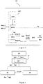
- the figure 1 is a schematic view of a device for radio transmission of an interrogation signal according to the invention
- the picture 2 is a detailed schematic view of a generator of a signal to be amplified of the radio transmission device of the figure 1 ;
- the picture 3 is a detailed schematic view of a signal generator pre-distortion device to be amplified from the figure 2 ;
- the figure 4 illustrates the steps of a method for radio transmission of an interrogation signal according to the invention.
- the figure 1 illustrates a device 10 for radio transmission of an interrogation signal according to the invention.
- the selection block 100 is capable of receiving a command K. From this command K, the selection block 100 provides information on the type of signal Type 1, Type 2 to be transmitted.
- the generator 200 is capable of receiving information on the type of Type 1 or Type 2 signal to be transmitted and of delivering a signal Sa1 or Sa2 to be amplified.
- the signal to be amplified Sa1 is associated with the signal type Type 1 and the signal to be amplified Sa2 is associated with the signal type Type 2.
- the power amplification chain 300 is adapted to amplify the signal to be amplified Sa1 or Sa2 with a view to forming an interrogation signal SA1 or SA2.
- the interrogation signal SA1 is associated with the signal to be amplified Sa1
- the interrogation signal SA2 is associated with the signal to be amplified Sa2.
- This amplification chain comprises at least two transistors (not shown on the figure 1 ). The amplification of the signal is thus carried out by several stages of amplification successive, in order to gradually increase the amplitude and power of the pulses without introducing noise.
- the interface module 400 is adapted to generate a trapezoidal signal Strapez intended to be applied as bias voltage in the power amplification chain 300 to emit each of the pulses of the interrogation signal SA1, SA2.
- this interface module 400 comprises two gate control signal generation blocks adapted to implement an adaptive gain, a pulse shaping generation block adapted to generate the Strapez trapezoidal signal so as to allow an adaptive gain and adaptive signal edges.
- the 400 interface module allows the use of pulse shaping, i.e.
- the radio transmission device 10 is here either configured as a mode S transponder for the transmission of a 1090 MHz interrogation signal SA1 or configured as a traffic alert system and collision avoidance for the transmission of a 1030 MHz interrogation signal SA2.
- the picture 2 illustrates in more detail the generator 200 of the figure 1 .
- Block 201 is suitable for shaping a wave characterizing an IFF transponder. This block 201 receives the Type 1 signal information and transmits an associated Wave1 waveform.
- Block 202 is suitable for shaping a wave characterizing a TCAS system with specific patterns (whisper/shout function) having different amplitudes on pulses spaced one microsecond apart.
- Block 302 receives the Type 2 signal information and outputs an associated Wave2 waveform.
- the device 203 is suitable for carrying out a pre-distortion of the signal pulses to be amplified on the carrier frequency.
- the successive stages of amplification have the effect of deforming the signal. In particular, they tend to straighten the fronts of the pulses, which has the effect of degrading the spectrum of the transmitted signal.
- the pre-distortion block 203 makes it possible to contain the transmissions in the desired spectral template and the temporal template.
- Block 203 is adapted to receive the Wave1 waveform or the Wave2 waveform. At the output, block 203 delivers a first signal Sp1 having undergone a pre-distortion on the waveform Wave1 or a second signal Sp2 having undergone a pre-distortion on the waveform Wave2.
- Block 203 also provides an adaptive gain G1.
- the RF amplifier 204 is adapted to amplify the first signal Sp1 or the second signal Sp2 from the adaptive gain G1. The amplification by the RF amplifier 204 is insufficient. This RF amplifier 204 will then deliver a first signal to be amplified Sa1 or a second signal to be amplified Sa2 intended for the power amplification chain 300 of the figure 1 .
- the 20311 control module is suitable for controlling pre-distortion. This control is done from a plurality of parameters such as frequency, power and/or temperature.
- the control module 20311 transmits control information Ic to the pre-distortion control module 20312.
- the pre-distortion control module 20312 is adapted to generate the adaptive gain G1 and a pre-distortion command Kp to the amplitude and phase adaptation module 20313.
- the 20312 control module includes an oscillator select block and an adaptive gain block.
- the oscillator selection block is able to select an oscillation frequency according to two different frequencies, that is to say, here, according to the 1090 MHz frequency or the 1030 MHz frequency. This choice of oscillation is linked to the Wave1 or Wave2 waveform received.
- the adaptation module 20313 is adapted to carry out an adaptation in amplitude and in phase of the waveform Wave1 or of the waveform Wave2 received from the pre-distortion command Kp received. This adaptation module 20313 then delivers an adaptation in amplitude Adapt(A), or an adaptation in phase Adapt(P).
- the digital-to-analog converter 2032 is suitable for converting an IQ signal to baseband or to an intermediate frequency. It receives from the adaptation module 20313 the amplitude adaptation and the phase adaptation. This converter converts the pre-distortion into an analog signal. This pre-distortion is necessary to guarantee the amplitude differences between pulses of the same train (a few hundred nanoseconds between pulses) in accordance with the standards.
- This digital-analog converter 2032 is suitable for transmitting a first analog signal Sana1 or a second analog signal Sana2 according to the waveform Wave1 or Wave2 adapted in amplitude and in phase.
- the 2033 modulator is suitable for modulating the IQ signal with an integrated synthesizer. More specifically, this modulator 2033 uses a preprogrammed bank to generate the transmit frequency to be frequency switched in a few microseconds. This 2033 module receives the first analog signal Sana1 or Sana2 and outputs the first signal Sp1 or the second signal Sp2.
- This radio transmission method comprises a step E1 of generating a signal to be amplified Sa1, Sa2.
- the pre-distortion is carried out for the pulses of the signal to be amplified Sa1, Sa2 on the carrier frequency.
- the signal Sa1, Sa2 is then amplified in a power amplification step E2 to form the interrogation signal SA1, SA2.
- the trapezoidal signal Strapez is applied as a bias voltage during the power amplification step E2.
- a type of interrogation signal to be transmitted is selected from among at least two different types of signals.
- the step E2 of power amplification of the signal to be amplified is configured so as to allow the transmission of the signal to be amplified Sa1, Sa2 for the generation of the interrogation signal SA1, SA2 corresponding to the type Type 1, Type 2 selected interrogation signal.
- the invention also relates to a transponder comprising the radio transmission device 10 or an airborne collision avoidance system X (ACAS-X) comprising such a transmission device 10.
- a transponder comprising the radio transmission device 10 or an airborne collision avoidance system X (ACAS-X) comprising such a transmission device 10.
- ACAS-X airborne collision avoidance system X
- the invention also relates to a computer program product comprising program instructions that can be used by the radio transmission device adapted to transmit the interrogation signal SA1, SA2 from the signal to be amplified Sa1, Sa2 which, when they are executed or interpreted by said transmission device 10 trigger the implementation of the method of radio transmission of the interrogation signal SA1, SA2.
Landscapes
- Engineering & Computer Science (AREA)
- Radar, Positioning & Navigation (AREA)
- Remote Sensing (AREA)
- Computer Networks & Wireless Communication (AREA)
- Physics & Mathematics (AREA)
- General Physics & Mathematics (AREA)
- Signal Processing (AREA)
- Aviation & Aerospace Engineering (AREA)
- Electromagnetism (AREA)
- Transmitters (AREA)
Abstract
Description
- La présente invention se situe dans le domaine des émissions RF (acronyme de radiofréquence) par impulsions, et porte plus précisément sur le contrôle du spectre d'émission de telles modulations. Elle s'applique en particulier aux modulations par impulsions utilisées dans le cadre des communications IFF (pour « Interrogation Friend and Foe » en anglais ou identification ami ou ennemi en français).
- Les transmissions IFF sont des transmissions utilisées en aéronautique dans la gamme de fréquence [1030 MHZ - 1090 MHZ] pour permettre aux radars d'approche, tant civils que militaires, de reconnaître des avions «amis» et de déterminer leur cap et leur distance. Les émissions IFF sont basées sur des trains d'impulsions transmis à forte puissance. Les communications IFF peuvent se faire selon différents modes (civils selon l'OACI annexe 10 (pour « International Civil Aviation Organization ») et militaires selon le STANAG 4193 (pour « NATO Standardization Agreements » en anglais, ou accords de normalisation en français), et diffèrent selon que l'on se trouve en interrogation ou en réponse. Les informations sont transmises en faisant varier la largeur des impulsions, leurs écarts relatifs, et/ou en introduisant aux impulsions une couche de modulation (typiquement une modulation DPSK (pour « Differential Phase Shift Keying » en anglais) ou MSK (pour « Minimum Shift Keying » en anglais). Les largeurs des impulsions et les écarts entre impulsions sont typiquement de l'ordre de quelques centaines de nano secondes.
- Les émissions IFF sont soumises à des contraintes importantes, définies entre autres par l'AIMS 03-1000b (pour «Air traffic control radar beacon system Identification friend and foe », Mark XII/XIIA System du département de la défense Américain), l'OACI annexe 10 volume IV, l'EUROCAE ED-73F (pour EUROpean Organisation for Civil Aviation Equipment), ou la norme DO260C du RTCA (pour « Radio Technical Commission for Aeronautics » en anglais), telle que RTCA DO-386 et RTCA DO181F (Mode S) compatibles avec le système d'évitement de collision aéroporté X (ACAS-X (pour « Airborne Collision Avoidance System » X en anglais)). Ces normes définissent entre autres les gabarits spectraux et temporels que doivent respecter les impulsions des émissions IFF.
- Le document
EP3337045 divulgue un dispositif d'émission radio d'un signal émis sous la forme d'une séquence d'impulsions. Ce dispositif comprend une partie de génération des impulsions sur fréquence porteuse et une chaîne analogique d'amplifications des impulsions avant leur émission. Cette chaîne d'amplification comprend une pluralité d'étages d'amplification successifs. Ce dispositif comprend un module de génération d'un signal de commande de forme sensiblement trapézoïdale. Ce signal de commande est appliqué en tant que tension de polarisation d'un amplificateur d'un étage de la chaîne d'amplification pour chacune des impulsions. Il est ainsi possible de contrôler le gabarit spectral du signal impulsionnel émis en modulant la polarisation d'un des amplificateurs de la chaîne d'amplification. Cette technique de contrôle est appelée « pulse shaping ». Elle remplace notamment le filtrage passe bande qui présente de nombreux inconvénients en terme de performance (pas de filtrage in-band, dégradation de l'EVM (pour « Error Vector Magnitude » en anglais) et dispersion en température), en terme de consommation (augmentation de la puissance de la chaîne pour compenser les pertes), en terme de fiabilité (impact du « return loss out band » sur les transistors et difficulté de réalisation du filtre) et en terme de coûts (composants coûteux). Le « pulse shaping » permet d'adresser avantageusement ces problèmes, mais n'a pour l'instant appliqué qu'à des chaines mono-fréquence. - Dès lors, si l'on souhaite délivrer deux types de signaux différents, par exemple, un signal à 1090 MHZ pour une fonction transpondeur Mode S ou un signal à 1030 MHZ pour une fonction TCAS, il faut mettre en place deux chaînes d'émissions séparées. Par « transpondeur Mode S», on entend un mode d'interrogation utilisé pour obtenir un certain nombre d'informations sur les avions équipés du système. Par «TCAS» (pour « Traffic Alert and Collision Avoidance System »), on entend un système interrogatif et coopératif qui questionne les transpondeurs des avions proches sur la fréquence 1030 MHZ. Ainsi, la fonction transpondeur Mode S et la fonction TCAS permettent de délivrer des signaux d'interrogation. Cependant, chacune de ces chaînes d'émission présente un poids et un volume propre. L'association de ces deux chaînes d'émission peut alors être incompatible dans des aéronefs de petite taille. En outre, la consommation n'est pas optimisée, ce qui est inconvénient majeur pour applications drones.
- Il existe donc un besoin de proposer un dispositif d'émission radio d'un signal d'interrogation qui puisse émettre différents types de signaux sur différentes fréquences compatibles avec les normes actuelles concernant les communications IFF.
- La présente invention vise à remédier au moins en partie à ce besoin.
- Plus particulièrement, la présente invention vise à améliorer l'encombrement d'un dispositif d'émission radio d'un signal d'interrogation, tout en le rendant compatible à l'émission de différents types de signaux d'interrogation.
- Un premier objet de l'invention concerne un dispositif d'émission radio d'un signal d'interrogation à partir d'un signal à amplifier, ledit signal d'interrogation comportant une pluralité d'impulsions. Le dispositif d'émission radio comprend un générateur d'un signal à amplifier, une chaîne d'amplification de puissance du signal à amplifier pour former un signal d'interrogation, un module d'interfaces adapté pour générer un signal trapézoïdal appliqué en tant que tension de polarisation dans la chaîne d'amplification de puissance pour émettre chacune des impulsions dudit signal d'interrogation. Le dispositif d'émission radio comprend un bloc de sélection d'un type de signal d'interrogation à émettre parmi au moins deux types de signaux différents. Le générateur de signal à amplifier est configuré de sorte à permettre l'émission d'un signal à amplifier, pour la génération du signal d'interrogation correspondant au type de signal d'interrogation sélectionné.
- Ainsi, il est possible d'obtenir un équipement avec une chaîne bi-fréquence. Le bloc de sélection est adapté pour sélectionner le type de signal d'interrogation à émettre. Cette sélection est, par exemple, une sélection automatique sous la forme d'une gestion des priorités entre les fonctionnalités TCAS et le répondeur IFF. La commutation rapide d'une fréquence à l'autre et la gestion de priorités, notamment par l'intermédiaire d'un logiciel, entre ces fonctionnalités TCAS et le répondeur IFF permettent de répondre à l'ensemble des contraintes normatives avec une seule chaîne d'émission.
- Dans un mode de réalisation particulier, selon un premier type de signal d'interrogation à émettre, le générateur de signal à amplifier est configuré comme un transpondeur mode S pour l'émission d'un signal d'interrogation de 1090 MHz.
- Un mode d'interrogation de transpondeur aéronautique est le format que prend une série d'impulsions émise par un radar secondaire ou un système équivalent, et le format, ou code, de la réponse de ce transpondeur. Ce mode d'interrogation est utilisé pour obtenir des informations sur les avions équipés du système. Dans sa forme la plus simple, un mode est généralement déterminé par l'espacement entre deux ou plusieurs impulsions d'interrogation. Il existe différents modes, 1 à 5 pour les militaires et A, B, C, D et le mode S pour l'usage civil. Le mode S retourne divers formats d'information sur une interrogation sélective. Chaque avion se voit attribuer une adresse fixe codée sur 24 bits.
- Dans un mode de réalisation particulier, selon un second type de signal d'interrogation à émettre, le générateur de signal à amplifier est configuré comme un système d'alerte de trafic et d'évitement de collision pour l'émission d'un signal d'interrogation de 1030 MHz.
- Le système utilisant un signal TCAS est un système interrogatif et coopératif qui questionne les transpondeurs des avions proches. Le système TCAS interroge toutes les secondes environ tous les avions dans sa zone de détection. En fonction des réponses, le système TCAS est capable de déterminer la position de ceux-ci en deux ou trois dimensions.
- Dans un mode de réalisation particulier, le générateur de signal à amplifier comprend un dispositif de pré-distorsion des impulsions du signal à amplifier sur fréquence porteuse.
- C'est la combinaison de la pré-distorsion du signal en amplitude et de la modulation de la tension de polarisation d'un avant dernier transistor (pulse shaping) qui permet de contrôler à la fois l'aspect temporel et le gabarit spectral du signal impulsionnel sur la même chaîne d'émission à la fois à la fréquence répondeur IFF et à la fois à la fréquence d'émission interrogateur IFF/TCAS.
- Dans un mode de réalisation particulier, le dispositif de pré-distorsion comprend un circuit logique programmable adapté pour piloter une adaptation d'une phase et d'une amplitude du signal à amplifier, un convertisseur numérique-analogique d'un signal IQ, un modulateur du signal IQ avec synthétiseur intégré.
- Dans un mode de réalisation particulier, le circuit logique programmable comprend un module de contrôle adapté pour le contrôle de la pré-distorsion, un module de commande de pré-distorsion, un module d'adaptation d'amplitude et de phase.
- Dans un mode de réalisation particulier, le module de contrôle effectue un contrôle à partir d'une pluralité de paramètres tels qu'une fréquence, une puissance et/ou une température.
- Un autre objet de l'invention concerne un procédé d'émission radio d'un signal d'interrogation à partir d'un signal à amplifier, ledit signal d'interrogation comportant une pluralité d'impulsions. Le procédé comporte une étape de génération d'un signal à amplifier, une étape d'amplification en puissance du signal à amplifier pour former un signal d'interrogation, une étape de génération d'un signal trapézoïdal appliqué en tant que tension de polarisation au cours de l'étape d'amplification en puissance pour émettre chacune des impulsions dudit signal d'interrogation. Le procédé d'émission radio comprend une étape de sélection d'un type de signal d'interrogation à émettre parmi au moins deux types de signaux différents, l'étape d'amplification en puissance du signal à amplifier étant configuré de sorte à permettre l'émission d'un signal à amplifier pour la génération du signal d'interrogation correspondant au type de signal d'interrogation sélectionné.
- Dans un mode de réalisation particulier, l'étape de génération du signal à amplifier comprend une étape de pré-distorsion des impulsions du signal à amplifier sur fréquence porteuse.
- Un autre objet de l'invention concerne un transpondeur comportant un dispositif d'émission radio selon l'un des objets précédents.
- Un autre objet de l'invention concerne un ACAS-X comportant un dispositif d'émission radio selon l'un des objets précédents.
- Un autre objet de l'invention concerne un programme d'ordinateur comportant des instructions de programme exploitables par un dispositif d'émission radio adapté pour émettre un signal d'interrogation à partir d'un signal à amplifier selon un des objets précédents qui lorsqu'elles sont exécutées ou interprétées par ledit dispositif d'émission déclenchent la mise en œuvre du procédé d'émission radio du signal d'interrogation selon un des objets précédents.
- La présente invention sera mieux comprise à la lecture de la description détaillée de modes de réalisation pris à titre d'exemples nullement limitatifs et illustrés par les dessins annexés sur lesquels :
- La
figure 1 est une vue schématique d'un dispositif d'émission radio d'un signal d'interrogation selon l'invention ; - La
figure 2 est une vue schématique détaillée d'un générateur d'un signal à amplifier du dispositif d'émission radio de lafigure 1 ; - La
figure 3 est une vue schématique détaillée d'un dispositif de pré-distorsion du générateur de signal à amplifier de lafigure 2 ; - La
figure 4 illustre les étapes d'un procédé d'émission radio d'un signal d'interrogation selon l'invention. - Sur les différentes figures, les éléments identiques ou similaires portent les mêmes références.
- La
figure 1 illustre un dispositif d'émission radio 10 d'un signal d'interrogation selon l'invention. - Ce dispositif d'émission radio 10 comprend :
- un bloc de sélection 100 ;
- un générateur 200 ;
- une chaîne d'amplification de puissance 300 ;
- un module d'interfaces 400.
- Le bloc de sélection 100 est apte à recevoir une commande K. A partir de cette commande K, le bloc de sélection 100 informe sur le type de signal Type 1, Type 2 à émettre.
- Le générateur 200 est apte à recevoir une information sur le type de signal Type 1 ou Type 2 à émettre et à délivrer un signal à amplifier Sa1 ou Sa2. Le signal à amplifier Sa1 est associé au type de signal Type 1 et le signal à amplifier Sa2 est associé au type de signal Type 2.
- La chaîne d'amplification de puissance 300 est adaptée pour amplifier le signal à amplifier Sa1 ou Sa2 en vue de former un signal d'interrogation SA1 ou SA2. Le signal d'interrogation SA1 est associé au signal à amplifier Sa1 et le signal d'interrogation SA2 est associé au signal à amplifier Sa2. Cette chaîne d'amplification comporte au moins deux transistors (non représentés sur la
figure 1 ). L'amplification du signal est ainsi réalisée par plusieurs étages d'amplification successifs, afin d'augmenter progressivement l'amplitude et la puissance des impulsions sans y introduire de bruit. - Le module d'interfaces 400 est adapté pour générer un signal trapézoïdal Strapez destiné à être appliqué en tant que tension de polarisation dans la chaîne d'amplification de puissance 300 pour émettre chacune des impulsions du signal d'interrogation SA1, SA2. Dans un mode de réalisation particulier non représenté sur la
figure 1 , ce module d'interfaces 400 comprend deux blocs de génération de signaux de contrôle de grille adaptés pour mettre en œuvre un gain adaptatif, un bloc de génération de pulse shaping adapté pour générer le signal trapézoïdal Strapez de sorte à permettre un gain adaptatif et des bords de signaux adaptatifs. Le module d'interfaces 400 permet l'utilisation du pulse shaping, c'est-à-dire la variation de la tension de polarisation de l'un des amplificateurs de la chaîne d'émission sur les périodes correspondant aux fronts montants et descendants des impulsions, afin de les mettre en forme de manière à respecter un gabarit spectral et des performances RF associées (temps de montée et de descente, bruit inter-pulse, respect de la réglementation ITU pour un train d'ondes en fonction de chaque fréquence, puissance et température). - On notera dès à présent que le dispositif d'émission radio 10 est ici soit configuré comme un transpondeur mode S pour l'émission d'un signal d'interrogation SA1 de 1090 MHZ soit configuré comme un système d'alerte de trafic et d'évitement de collision pour l'émission d'un signal d'interrogation SA2 de 1030 MHZ.
- La
figure 2 illustre plus en détail le générateur 200 de lafigure 1 . - Ce générateur 200 comprend :
- un bloc 201 de mise en forme d'onde IFF ;
- un bloc 202 de mise en forme d'onde TCAS ;
- un dispositif 203 de pré-distorsion ;
- un amplificateur RF 204.
- Le bloc 201 est adapté pour mettre en forme une onde caractérisant un transpondeur IFF. Ce bloc 201 reçoit l'information du signal Type 1 et émet une forme d'onde Wave1 associée.
- Le bloc 202 est adapté pour mettre en forme une onde caractérisant un système TCAS avec des patterns spécifiques (fonction whisper/shout) ayant des amplitudes différentes sur des pulses espacés d'une microseconde. Le bloc 302 reçoit l'information du signal Type 2 et émet une forme d'onde Wave2 associée.
- Le dispositif 203 est adapté pour réaliser une pré-distorsion des impulsions du signal à amplifier sur la fréquence porteuse. Les étages successifs d'amplification ont pour effet de déformer le signal. En particulier, ils ont tendance à redresser les fronts des impulsions, ce qui a pour effet de dégrader le spectre du signal émis. Le bloc 203 de pré-distorsion permet de contenir les émissions dans le gabarit spectral et le gabarit temporel souhaités. Le bloc 203 est adapté pour recevoir la forme d'onde Wave1 ou la forme d'onde Wave2. En sortie, le bloc 203 délivre un premier signal Sp1 ayant subi une pré-distorsion sur la forme d'onde Wave1 ou un second signal Sp2 ayant subi une pré-distorsion sur la forme d'onde Wave2. Le bloc 203 délivre également un gain adaptatif G1.
- L'amplificateur RF 204 est adaptée pour amplifier le premier signal Sp1 ou le second signal Sp2 à partir du gain adaptatif G1. L'amplification par l'amplificateur RF 204 est insuffisante. Cet amplificateur RF 204 va alors délivrer un premier signal à amplifier Sa1 ou un second signal à amplifier Sa2 à destination de la chaîne d'amplification de puissance 300 de la
figure 1 . - La
figure 3 détaille le dispositif 203 de pré-distorsion. Ce dispositif 203 comprend : - un circuit logique programmable 2031 ;
- un convertisseur numérique-analogique 2032 ;
- un modulateur 2033.
- Le circuit logique programmable 2031 est apte à piloter une adaptation d'une phase et d'une amplitude du signal à amplifier. Il reçoit la forme d'onde Wave1 ou la forme d'onde Wave2 délivrée par le bloc 201 ou le bloc 202. Ce circuit logique programmable 2031 comprend :
- un module de contrôle 20311 adapté pour contrôler la pré-distorsion ;
- un module de commande 20312 de pré-distorsion ;
- un module d'adaptation 20313.
- Le module de contrôle 20311 est adapté pour contrôler la pré-distorsion. Ce contrôle se fait à partir d'une pluralité de paramètres tels qu'une fréquence, une puissance et/ou une température. Le module de contrôle 20311 transmet une information de contrôle Ic au module de commande 20312 de pré-distorsion.
- Le module de commande 20312 de pré-distorsion est adapté pour générer le gain adaptatif G1 et une commande de pré-distorsion Kp au module d'adaptation 20313 d'amplitude et de phase. Dans un mode de réalisation particulier non illustré sur la
figure 3 , le module de commande 20312 comprend un bloc de sélection d'oscillateur et un bloc de gain adaptatif. Le bloc de sélection d'oscillateur est apte à sélectionner une fréquence d'oscillation selon deux fréquences différentes, c'est-à-dire, ici, selon la fréquence 1090 MHZ ou la fréquence 1030 MHZ. Ce choix d'oscillation est lié à la forme d'onde Wave1 ou Wave2 reçue. - Le module d'adaptation 20313 est adapté pour effectuer une adaptation en amplitude et en phase de la forme d'onde Wave1 ou de la forme d'onde Wave2 reçue à partir de la commande de pré-distorsion Kp reçue. Ce module d'adaptation 20313 délivre alors une adaptation en amplitude Adapt(A), ou une adaptation en phase Adapt(P).
- Le convertisseur numérique-analogique 2032 est adapté pour convertir un signal IQ en bande de base ou sur une fréquence intermédiaire. Il reçoit du module d'adaptation 20313 l'adaptation en amplitude et l'adaptation en phase. Ce convertisseur permet de convertir la pré-distorsion en signal analogique. Cette pré-distorsion est nécessaire pour garantir les différences d'amplitudes entre pulses d'un même train (quelques centaines de nanosecondes entre pulses) conformément aux normes. Ce convertisseur numérique-analogique 2032 est adapté pour transmettre un premier signal analogique Sana1 ou un second signal analogique Sana2 selon la forme d'onde Wave1 ou Wave2 adaptée en amplitude et en phase.
- Le modulateur 2033 est adapté pour moduler le signal IQ avec un synthétiseur intégré. Plus particulièrement, ce modulateur 2033 utilise une banque préprogrammée pour générer la fréquence d'émission à commuter de fréquence en quelques microsecondes. Ce module 2033 reçoit le premier signal analogique Sana1 ou Sana2 et émet en sortie le premier signal Sp1 ou le second signal Sp2.
- Un procédé d'émission radio d'un signal d'interrogation va être décrit à l'appui des
figures 1 à 3 et de lafigure 4 . - Ce procédé d'émission radio comporte une étape E1 de génération d'un signal à amplifier Sa1, Sa2. Dans une sous-étape E11 de l'étape E1 de génération, la pré-distorsion est réalisée pour les impulsions du signal à amplifier Sa1, Sa2 sur la fréquence porteuse.
- Le signal Sa1, Sa2 est ensuite amplifié dans une étape E2 d'amplification en puissance pour former le signal d'interrogation SA1, SA2.
- Dans une étape E3, le signal trapézoïdal Strapez est appliqué en tant que tension de polarisation au cours de l'étape E2 d'amplification en puissance.
- Dans une étape E0 préalable aux étapes E1 à E3, un type de signal d'interrogation à émettre est sélectionné parmi au moins deux types de signaux différents. Ainsi, l'étape E2 d'amplification en puissance du signal à amplifier est configurée de sorte à permettre l'émission du signal à amplifier Sa1, Sa2 pour la génération du signal d'interrogation SA1, SA2 correspondant au type Type 1, Type 2 de signal d'interrogation sélectionné.
- Le dispositif radio 10 apporte les avantages suivants :
- il permet d'utiliser une seul chaîne d'émission pour les deux fréquences au lieu de deux pour assurer les fonctions répondeurs et TCAS ;
- il permet de diviser par deux le nombre d'antennes nécessaires ce qui réduit le poids le volume et la consommation ;
- il permet d'utiliser de la pré-distorsion sur les entrées IQ au lieu de la commutation sur un atténuateur pour réaliser la fonction whisper/shout ;
- il permet d'utiliser du pulse shaping numérique à la place d'un filtrage en puissance pour respecter un gabarit spectral sur une seule voie ;
- il permet de gérer les différents niveaux d'émission TCAS par contrôle des gains des premiers étages de la chaine d'amplification par programmation des composants entre les trains (1 ms en typique).
- L'invention concerne également un transpondeur comportant le dispositif d'émission radio 10 ou un système d'évitement de collision aéroporté X (ACAS-X) comportant un tel dispositif d'émission 10.
- L'invention concerne également un produit programme d'ordinateur comportant des instructions de programme exploitables par le dispositif d'émission radio adapté pour émettre le signal d'interrogation SA1, SA2 à partir du signal à amplifier Sa1, Sa2 qui lorsqu'elles sont exécutées ou interprétées par ledit dispositif d'émission 10 déclenchent la mise en œuvre du procédé d'émission radio du signal d'interrogation SA1, SA2.
- L'invention n'est pas limitée aux modes de réalisation et variantes présentées et d'autres modes de réalisation et variantes apparaîtront clairement à l'homme du métier.
Claims (12)
- Dispositif d'émission radio d'un signal d'interrogation (SA1, SA2) à partir d'un signal à amplifier (Sa1, Sa2), ledit signal d'interrogation (SA1, SA2) comportant une pluralité d'impulsions, ledit dispositif d'émission radio (10) comprenant :- un générateur (200) d'un signal à amplifier (Sa1, Sa2) ;- une chaîne d'amplification de puissance (300) du signal à amplifier (Sa1, Sa2) pour former un signal d'interrogation (SA1, SA2) ;- un module d'interfaces (400) apte à générer un signal trapézoïdal (Strapez) appliqué en tant que tension de polarisation dans la chaîne d'amplification de puissance (300) pour émettre chacune des impulsions dudit signal d'interrogation (SA1, SA2) ;caractérisé en ce que ledit dispositif d'émission radio (10) comprend un bloc de sélection (100) d'un type de signal d'interrogation à émettre parmi au moins deux types (Type 1, Type 2) de signaux différents, ledit générateur (200) de signal à amplifier étant configuré de sorte à permettre l'émission d'un signal à amplifier (Sa1, Sa2), pour la génération du signal d'interrogation (SA1, SA2) correspondant au type (Type 1, Type 2) de signal d'interrogation sélectionné.
- Dispositif d'émission selon la revendication 1, dans lequel selon un premier type (Type 1) de signal d'interrogation (SA1) à émettre, le dispositif d'émission radio (10) est configuré comme un transpondeur mode S pour l'émission d'un signal d'interrogation de 1090 MHz.
- Dispositif d'émission selon l'une quelconque des revendications 1 ou 2, dans lequel selon un second type (Type 2) de signal d'interrogation (SA2) à émettre, le dispositif d'émission radio (10) est configuré comme un système d'alerte de trafic et d'évitement de collision pour l'émission d'un signal d'interrogation de 1030 MHz.
- Dispositif d'émission selon l'une quelconque des revendications 1 à 3, dans lequel le générateur (200) de signal à amplifier (Sa1, Sa2) comprend un dispositif (203) de pré-distorsion des impulsions du signal à amplifier (Sa1, Sa2) sur fréquence porteuse.
- Dispositif d'émission selon l'une quelconque des revendications 1 à 4, dans lequel le dispositif de pré-distorsion (203) comprend :- un circuit logique programmable (2031) apte à piloter une adaptation d'une phase et d'une amplitude du signal à amplifier ;- un convertisseur numérique-analogique (2032) d'un signal IQ ;- un modulateur (2033) du signal IQ avec synthétiseur intégré.
- Dispositif d'émission selon la revendication 5, dans lequel le circuit logique programmable (2031) comprend :- un module de contrôle (20311) adapté pour le contrôle de la pré-distorsion ;- un module de commande (20312) de pré-distorsion ;- un module d'adaptation (20313) d'amplitude et de phase.
- Dispositif d'émission selon la revendication 6, dans lequel le module de contrôle (20311) effectue un contrôle à partir d'une pluralité de paramètres tels qu'une fréquence, une puissance et/ou une température.
- Procédé d'émission radio d'un signal d'interrogation à partir d'un signal à amplifier (Sa1, Sa2), ledit signal d'interrogation (SA1, SA2) comportant une pluralité d'impulsions, ledit procédé comportant :- une étape (E1 ) de génération d'un signal à amplifier (Sa1, Sa2) ;- une étape (E2) d'amplification en puissance du signal à amplifier (Sa1, Sa2) pour former un signal d'interrogation (SA1, SA2) ;- une étape (E3) de génération d'un signal trapézoïdal (Strapez) appliqué en tant que tension de polarisation au cours de l'étape (E2) d'amplification en puissance pour émettre chacune des impulsions dudit signal d'interrogation (SA1, SA2) ;- caractérisé en ce que ledit procédé d'émission radio comprend :- une étape (E0) de sélection (100) d'un type de signal d'interrogation à émettre parmi au moins deux types (Type 1, Type 2) de signaux différents, l'étape (E2) d'amplification en puissance du signal à amplifier étant configuré de sorte à permettre l'émission d'un signal à amplifier (Sa1, Sa2) pour la génération du signal d'interrogation (SA1, SA2) correspondant au type (Type 1, Type 2) de signal d'interrogation sélectionné.
- Procédé d'émission selon la revendication 8, dans lequel l'étape de génération (E1) du signal à amplifier comprend une étape (E11) de pré-distorsion des impulsions du signal à amplifier (Sa1, Sa2) sur fréquence porteuse.
- Transpondeur comportant un dispositif d'émission radio (10) selon l'une quelconque des revendications 1 à 7.
- ACAS-X comportant un dispositif d'émission radio (10) selon l'une quelconque des revendications 1 à 7.
- Produit programme d'ordinateur comportant des instructions de programme exploitables par un dispositif d'émission radio (10) adapté pour émettre un signal d'interrogation (SA1, SA2) à partir d'un signal à amplifier (Sa1, Sa2) selon l'une quelconque des revendications 1 à 7, qui lorsqu'elles sont exécutées ou interprétées par ledit dispositif d'émission (10) déclenchent la mise en œuvre du procédé d'émission radio du signal d'interrogation (SA1, SA2) selon l'une quelconque des revendications 8 à 9.
Applications Claiming Priority (1)
| Application Number | Priority Date | Filing Date | Title |
|---|---|---|---|
| FR2013991A FR3118191B1 (fr) | 2020-12-23 | 2020-12-23 | Dispositif d'emission radio d'un signal d'interrogation a partir d'un signal a amplifier |
Publications (2)
| Publication Number | Publication Date |
|---|---|
| EP4020011A1 true EP4020011A1 (fr) | 2022-06-29 |
| EP4020011B1 EP4020011B1 (fr) | 2025-09-03 |
Family
ID=76159462
Family Applications (1)
| Application Number | Title | Priority Date | Filing Date |
|---|---|---|---|
| EP21216644.1A Active EP4020011B1 (fr) | 2020-12-23 | 2021-12-21 | Dispositif d'émission radio d'un signal d'interrogation à partir d'un signal à amplifier |
Country Status (5)
| Country | Link |
|---|---|
| US (1) | US11848813B2 (fr) |
| EP (1) | EP4020011B1 (fr) |
| ES (1) | ES3057233T3 (fr) |
| FR (1) | FR3118191B1 (fr) |
| PL (1) | PL4020011T3 (fr) |
Citations (2)
| Publication number | Priority date | Publication date | Assignee | Title |
|---|---|---|---|---|
| US20050156777A1 (en) * | 2004-01-15 | 2005-07-21 | Honeywell International, Inc. | Integrated traffic surveillance apparatus |
| EP3337045A1 (fr) | 2016-12-15 | 2018-06-20 | Thales | Controle du spectre d'une émission rf impulsionnelle par mise en forme des impulsions |
Family Cites Families (3)
| Publication number | Priority date | Publication date | Assignee | Title |
|---|---|---|---|---|
| US3927404A (en) * | 1973-10-18 | 1975-12-16 | Standard Electric Time Corp | Time division multiple access communication system for status monitoring |
| US7787564B1 (en) * | 2007-03-13 | 2010-08-31 | Kiomars Anvari | Combined peak reduction equalizer and phase/amplitude pre-distortion |
| KR101473758B1 (ko) * | 2008-11-28 | 2014-12-17 | 삼성전자주식회사 | 복수의 안테나를 구비한 릴레이를 경유하여 데이터를 전송하는 데이터 전송 시스템 |
-
2020
- 2020-12-23 FR FR2013991A patent/FR3118191B1/fr active Active
-
2021
- 2021-12-21 ES ES21216644T patent/ES3057233T3/es active Active
- 2021-12-21 EP EP21216644.1A patent/EP4020011B1/fr active Active
- 2021-12-21 US US17/558,245 patent/US11848813B2/en active Active
- 2021-12-21 PL PL21216644.1T patent/PL4020011T3/pl unknown
Patent Citations (2)
| Publication number | Priority date | Publication date | Assignee | Title |
|---|---|---|---|---|
| US20050156777A1 (en) * | 2004-01-15 | 2005-07-21 | Honeywell International, Inc. | Integrated traffic surveillance apparatus |
| EP3337045A1 (fr) | 2016-12-15 | 2018-06-20 | Thales | Controle du spectre d'une émission rf impulsionnelle par mise en forme des impulsions |
Also Published As
| Publication number | Publication date |
|---|---|
| US11848813B2 (en) | 2023-12-19 |
| ES3057233T3 (en) | 2026-02-27 |
| FR3118191A1 (fr) | 2022-06-24 |
| US20220200836A1 (en) | 2022-06-23 |
| FR3118191B1 (fr) | 2023-12-01 |
| PL4020011T3 (pl) | 2026-03-16 |
| EP4020011B1 (fr) | 2025-09-03 |
Similar Documents
| Publication | Publication Date | Title |
|---|---|---|
| Griffiths et al. | Radar spectrum engineering and management: Technical and regulatory issues | |
| US5861834A (en) | Virtual noise radar waveform for reduced radar detectability | |
| JP4544866B2 (ja) | 自動車及び他の商業用途用のパルス圧縮レーダシステム | |
| US5821895A (en) | Method and device for locating and identifying objects by means of an encoded transponder | |
| EP3121902B1 (fr) | Dispositif radioélectrique d'émission-réception d'ondes radioélectriques et système de radio altimétrie associé | |
| EP3321711B1 (fr) | Dispositif de reception pour antenne a balayage electronique apte a fonctionner en mode radar et resm, et radar equipe d'un tel dispositif | |
| US3945012A (en) | Wide band pulsed energy system | |
| EP1998441A2 (fr) | Controle automatique de gain asservi sur la densité de probabilité de puissance reçue | |
| CA2439563A1 (fr) | Dispositif et procede de suppression de signaux radioelectriques pulses | |
| RU2615996C1 (ru) | Сверхширокополосный радиолокатор с активной многочастотной антенной решеткой | |
| EP4020011B1 (fr) | Dispositif d'émission radio d'un signal d'interrogation à partir d'un signal à amplifier | |
| EP2438461B1 (fr) | Procédé de détection d'un message émis par un interrogateur ou un répondeur en mode s | |
| US10637585B1 (en) | Secure optical communication and target designation using frequency tuning, hopping , and encoding | |
| US7106245B2 (en) | Digital RF tag | |
| US20040061640A1 (en) | Broadband radar and modulator, in particular for microwave switching over a very short period | |
| US7064703B2 (en) | Methods and apparatus for randomly modulating radar altimeters | |
| RU2507538C2 (ru) | Способ группового опознавания объектов ("свой-чужой") и обеспечения целеуказания на основе беспроводной системы позиционирования в реальном масштабе времени и интеллектуальных радаров | |
| EP3337045B1 (fr) | Controle du spectre d'une émission rf impulsionnelle par mise en forme des impulsions | |
| Aubry et al. | Assessing radar waveforms for spectral coexistence via the parsax system | |
| EP1736795A1 (fr) | Radar a impulsions courtes et procede de controle associe | |
| Feng et al. | High-resolution chaos LiDAR using self-phase-modulated feedback external-cavity semiconductor laser-based chaos source | |
| WO2005038487A1 (fr) | Procédé et dispositif de filtrage d'un signal vidéo reçu par un radar secondaire, notamment pour éliminer les réponses mode s | |
| EP2341363B1 (fr) | Système de réponse à un signal émis par un radar et utilisation de ce système notamment pour tester les radars, en particulier de type MTI | |
| Suna Yazar et al. | Frequency-shifted FMCW method against DRFM spoofing attacks | |
| CA1221755A (fr) | Materiel radio de signalisation |
Legal Events
| Date | Code | Title | Description |
|---|---|---|---|
| PUAI | Public reference made under article 153(3) epc to a published international application that has entered the european phase |
Free format text: ORIGINAL CODE: 0009012 |
|
| STAA | Information on the status of an ep patent application or granted ep patent |
Free format text: STATUS: THE APPLICATION HAS BEEN PUBLISHED |
|
| AK | Designated contracting states |
Kind code of ref document: A1 Designated state(s): AL AT BE BG CH CY CZ DE DK EE ES FI FR GB GR HR HU IE IS IT LI LT LU LV MC MK MT NL NO PL PT RO RS SE SI SK SM TR |
|
| STAA | Information on the status of an ep patent application or granted ep patent |
Free format text: STATUS: REQUEST FOR EXAMINATION WAS MADE |
|
| 17P | Request for examination filed |
Effective date: 20221227 |
|
| RBV | Designated contracting states (corrected) |
Designated state(s): AL AT BE BG CH CY CZ DE DK EE ES FI FR GB GR HR HU IE IS IT LI LT LU LV MC MK MT NL NO PL PT RO RS SE SI SK SM TR |
|
| P01 | Opt-out of the competence of the unified patent court (upc) registered |
Effective date: 20230517 |
|
| STAA | Information on the status of an ep patent application or granted ep patent |
Free format text: STATUS: EXAMINATION IS IN PROGRESS |
|
| 17Q | First examination report despatched |
Effective date: 20240313 |
|
| GRAP | Despatch of communication of intention to grant a patent |
Free format text: ORIGINAL CODE: EPIDOSNIGR1 |
|
| STAA | Information on the status of an ep patent application or granted ep patent |
Free format text: STATUS: GRANT OF PATENT IS INTENDED |
|
| INTG | Intention to grant announced |
Effective date: 20250414 |
|
| GRAS | Grant fee paid |
Free format text: ORIGINAL CODE: EPIDOSNIGR3 |
|
| GRAA | (expected) grant |
Free format text: ORIGINAL CODE: 0009210 |
|
| STAA | Information on the status of an ep patent application or granted ep patent |
Free format text: STATUS: THE PATENT HAS BEEN GRANTED |
|
| AK | Designated contracting states |
Kind code of ref document: B1 Designated state(s): AL AT BE BG CH CY CZ DE DK EE ES FI FR GB GR HR HU IE IS IT LI LT LU LV MC MK MT NL NO PL PT RO RS SE SI SK SM TR |
|
| RAP3 | Party data changed (applicant data changed or rights of an application transferred) |
Owner name: THALES |
|
| REG | Reference to a national code |
Ref country code: CH Ref legal event code: EP |
|
| REG | Reference to a national code |
Ref country code: DE Ref legal event code: R096 Ref document number: 602021037645 Country of ref document: DE |
|
| REG | Reference to a national code |
Ref country code: IE Ref legal event code: FG4D Free format text: LANGUAGE OF EP DOCUMENT: FRENCH |
|
| REG | Reference to a national code |
Ref country code: NL Ref legal event code: MP Effective date: 20250903 |
|
| PGFP | Annual fee paid to national office [announced via postgrant information from national office to epo] |
Ref country code: DE Payment date: 20251126 Year of fee payment: 5 |
|
| PGFP | Annual fee paid to national office [announced via postgrant information from national office to epo] |
Ref country code: GB Payment date: 20251127 Year of fee payment: 5 |
|
| PG25 | Lapsed in a contracting state [announced via postgrant information from national office to epo] |
Ref country code: NO Free format text: LAPSE BECAUSE OF FAILURE TO SUBMIT A TRANSLATION OF THE DESCRIPTION OR TO PAY THE FEE WITHIN THE PRESCRIBED TIME-LIMIT Effective date: 20251203 |
|
| REG | Reference to a national code |
Ref country code: LT Ref legal event code: MG9D |
|
| PGFP | Annual fee paid to national office [announced via postgrant information from national office to epo] |
Ref country code: AT Payment date: 20260113 Year of fee payment: 5 |
|
| PG25 | Lapsed in a contracting state [announced via postgrant information from national office to epo] |
Ref country code: FI Free format text: LAPSE BECAUSE OF FAILURE TO SUBMIT A TRANSLATION OF THE DESCRIPTION OR TO PAY THE FEE WITHIN THE PRESCRIBED TIME-LIMIT Effective date: 20250903 |
|
| PGFP | Annual fee paid to national office [announced via postgrant information from national office to epo] |
Ref country code: IT Payment date: 20251217 Year of fee payment: 5 |
|
| PG25 | Lapsed in a contracting state [announced via postgrant information from national office to epo] |
Ref country code: HR Free format text: LAPSE BECAUSE OF FAILURE TO SUBMIT A TRANSLATION OF THE DESCRIPTION OR TO PAY THE FEE WITHIN THE PRESCRIBED TIME-LIMIT Effective date: 20250903 |
|
| PGFP | Annual fee paid to national office [announced via postgrant information from national office to epo] |
Ref country code: FR Payment date: 20251128 Year of fee payment: 5 |
|
| PG25 | Lapsed in a contracting state [announced via postgrant information from national office to epo] |
Ref country code: GR Free format text: LAPSE BECAUSE OF FAILURE TO SUBMIT A TRANSLATION OF THE DESCRIPTION OR TO PAY THE FEE WITHIN THE PRESCRIBED TIME-LIMIT Effective date: 20251204 |
|
| PGFP | Annual fee paid to national office [announced via postgrant information from national office to epo] |
Ref country code: TR Payment date: 20251219 Year of fee payment: 5 |
|
| PG25 | Lapsed in a contracting state [announced via postgrant information from national office to epo] |
Ref country code: SE Free format text: LAPSE BECAUSE OF FAILURE TO SUBMIT A TRANSLATION OF THE DESCRIPTION OR TO PAY THE FEE WITHIN THE PRESCRIBED TIME-LIMIT Effective date: 20250903 |
|
| PG25 | Lapsed in a contracting state [announced via postgrant information from national office to epo] |
Ref country code: LV Free format text: LAPSE BECAUSE OF FAILURE TO SUBMIT A TRANSLATION OF THE DESCRIPTION OR TO PAY THE FEE WITHIN THE PRESCRIBED TIME-LIMIT Effective date: 20250903 |
|
| PG25 | Lapsed in a contracting state [announced via postgrant information from national office to epo] |
Ref country code: BG Free format text: LAPSE BECAUSE OF FAILURE TO SUBMIT A TRANSLATION OF THE DESCRIPTION OR TO PAY THE FEE WITHIN THE PRESCRIBED TIME-LIMIT Effective date: 20250903 |
|
| PG25 | Lapsed in a contracting state [announced via postgrant information from national office to epo] |
Ref country code: RS Free format text: LAPSE BECAUSE OF FAILURE TO SUBMIT A TRANSLATION OF THE DESCRIPTION OR TO PAY THE FEE WITHIN THE PRESCRIBED TIME-LIMIT Effective date: 20251203 |
|
| REG | Reference to a national code |
Ref country code: AT Ref legal event code: MK05 Ref document number: 1833674 Country of ref document: AT Kind code of ref document: T Effective date: 20250903 |
|
| PG25 | Lapsed in a contracting state [announced via postgrant information from national office to epo] |
Ref country code: NL Free format text: LAPSE BECAUSE OF FAILURE TO SUBMIT A TRANSLATION OF THE DESCRIPTION OR TO PAY THE FEE WITHIN THE PRESCRIBED TIME-LIMIT Effective date: 20250903 |
|
| REG | Reference to a national code |
Ref country code: ES Ref legal event code: FG2A Ref document number: 3057233 Country of ref document: ES Kind code of ref document: T3 Effective date: 20260227 |
|
| PG25 | Lapsed in a contracting state [announced via postgrant information from national office to epo] |
Ref country code: SM Free format text: LAPSE BECAUSE OF FAILURE TO SUBMIT A TRANSLATION OF THE DESCRIPTION OR TO PAY THE FEE WITHIN THE PRESCRIBED TIME-LIMIT Effective date: 20250903 |
|
| PGFP | Annual fee paid to national office [announced via postgrant information from national office to epo] |
Ref country code: ES Payment date: 20260114 Year of fee payment: 5 |
|
| PG25 | Lapsed in a contracting state [announced via postgrant information from national office to epo] |
Ref country code: AT Free format text: LAPSE BECAUSE OF FAILURE TO SUBMIT A TRANSLATION OF THE DESCRIPTION OR TO PAY THE FEE WITHIN THE PRESCRIBED TIME-LIMIT Effective date: 20250903 |
|
| PG25 | Lapsed in a contracting state [announced via postgrant information from national office to epo] |
Ref country code: RO Free format text: LAPSE BECAUSE OF FAILURE TO SUBMIT A TRANSLATION OF THE DESCRIPTION OR TO PAY THE FEE WITHIN THE PRESCRIBED TIME-LIMIT Effective date: 20250903 |
|
| PG25 | Lapsed in a contracting state [announced via postgrant information from national office to epo] |
Ref country code: IS Free format text: LAPSE BECAUSE OF FAILURE TO SUBMIT A TRANSLATION OF THE DESCRIPTION OR TO PAY THE FEE WITHIN THE PRESCRIBED TIME-LIMIT Effective date: 20260103 |
|
| PG25 | Lapsed in a contracting state [announced via postgrant information from national office to epo] |
Ref country code: CZ Free format text: LAPSE BECAUSE OF FAILURE TO SUBMIT A TRANSLATION OF THE DESCRIPTION OR TO PAY THE FEE WITHIN THE PRESCRIBED TIME-LIMIT Effective date: 20250903 Ref country code: PT Free format text: LAPSE BECAUSE OF FAILURE TO SUBMIT A TRANSLATION OF THE DESCRIPTION OR TO PAY THE FEE WITHIN THE PRESCRIBED TIME-LIMIT Effective date: 20260105 |
|
| PGFP | Annual fee paid to national office [announced via postgrant information from national office to epo] |
Ref country code: PL Payment date: 20251208 Year of fee payment: 5 |
|
| PG25 | Lapsed in a contracting state [announced via postgrant information from national office to epo] |
Ref country code: EE Free format text: LAPSE BECAUSE OF FAILURE TO SUBMIT A TRANSLATION OF THE DESCRIPTION OR TO PAY THE FEE WITHIN THE PRESCRIBED TIME-LIMIT Effective date: 20250903 Ref country code: SK Free format text: LAPSE BECAUSE OF FAILURE TO SUBMIT A TRANSLATION OF THE DESCRIPTION OR TO PAY THE FEE WITHIN THE PRESCRIBED TIME-LIMIT Effective date: 20250903 |
|
| REG | Reference to a national code |
Ref country code: DE Ref legal event code: R097 Ref document number: 602021037645 Country of ref document: DE |
|
| PG25 | Lapsed in a contracting state [announced via postgrant information from national office to epo] |
Ref country code: LT Free format text: LAPSE BECAUSE OF FAILURE TO SUBMIT A TRANSLATION OF THE DESCRIPTION OR TO PAY THE FEE WITHIN THE PRESCRIBED TIME-LIMIT Effective date: 20250903 |
|
| PG25 | Lapsed in a contracting state [announced via postgrant information from national office to epo] |
Ref country code: MC Free format text: LAPSE BECAUSE OF FAILURE TO SUBMIT A TRANSLATION OF THE DESCRIPTION OR TO PAY THE FEE WITHIN THE PRESCRIBED TIME-LIMIT Effective date: 20250903 |
|
| PG25 | Lapsed in a contracting state [announced via postgrant information from national office to epo] |
Ref country code: DK Free format text: LAPSE BECAUSE OF FAILURE TO SUBMIT A TRANSLATION OF THE DESCRIPTION OR TO PAY THE FEE WITHIN THE PRESCRIBED TIME-LIMIT Effective date: 20250903 |
|
| PLBE | No opposition filed within time limit |
Free format text: ORIGINAL CODE: 0009261 |
|
| STAA | Information on the status of an ep patent application or granted ep patent |
Free format text: STATUS: NO OPPOSITION FILED WITHIN TIME LIMIT |
|
| REG | Reference to a national code |
Ref country code: CH Ref legal event code: L10 Free format text: ST27 STATUS EVENT CODE: U-0-0-L10-L00 (AS PROVIDED BY THE NATIONAL OFFICE) Effective date: 20260715 |
|
| REG | Reference to a national code |
Ref country code: CH Ref legal event code: H13 Free format text: ST27 STATUS EVENT CODE: U-0-0-H10-H13 (AS PROVIDED BY THE NATIONAL OFFICE) Effective date: 20260723 |
|
| 26N | No opposition filed |
Effective date: 20260604 |