EP4019936B1 - Membranstruktur für sandproduktionstest - Google Patents
Membranstruktur für sandproduktionstest Download PDFInfo
- Publication number
- EP4019936B1 EP4019936B1 EP20383147.4A EP20383147A EP4019936B1 EP 4019936 B1 EP4019936 B1 EP 4019936B1 EP 20383147 A EP20383147 A EP 20383147A EP 4019936 B1 EP4019936 B1 EP 4019936B1
- Authority
- EP
- European Patent Office
- Prior art keywords
- membrane structure
- fluid
- base plate
- wall
- rock sample
- Prior art date
- Legal status (The legal status is an assumption and is not a legal conclusion. Google has not performed a legal analysis and makes no representation as to the accuracy of the status listed.)
- Active
Links
Images


Classifications
-
- G—PHYSICS
- G01—MEASURING; TESTING
- G01N—INVESTIGATING OR ANALYSING MATERIALS BY DETERMINING THEIR CHEMICAL OR PHYSICAL PROPERTIES
- G01N3/00—Investigating strength properties of solid materials by application of mechanical stress
- G01N3/08—Investigating strength properties of solid materials by application of mechanical stress by applying steady tensile or compressive forces
- G01N3/10—Investigating strength properties of solid materials by application of mechanical stress by applying steady tensile or compressive forces generated by pneumatic or hydraulic pressure
- G01N3/12—Pressure testing
-
- G—PHYSICS
- G01—MEASURING; TESTING
- G01N—INVESTIGATING OR ANALYSING MATERIALS BY DETERMINING THEIR CHEMICAL OR PHYSICAL PROPERTIES
- G01N15/00—Investigating characteristics of particles; Investigating permeability, pore-volume or surface-area of porous materials
- G01N15/08—Investigating permeability, pore-volume, or surface area of porous materials
- G01N15/0806—Details, e.g. sample holders, mounting samples for testing
-
- G—PHYSICS
- G01—MEASURING; TESTING
- G01N—INVESTIGATING OR ANALYSING MATERIALS BY DETERMINING THEIR CHEMICAL OR PHYSICAL PROPERTIES
- G01N3/00—Investigating strength properties of solid materials by application of mechanical stress
- G01N3/02—Details
-
- G—PHYSICS
- G01—MEASURING; TESTING
- G01N—INVESTIGATING OR ANALYSING MATERIALS BY DETERMINING THEIR CHEMICAL OR PHYSICAL PROPERTIES
- G01N3/00—Investigating strength properties of solid materials by application of mechanical stress
- G01N3/08—Investigating strength properties of solid materials by application of mechanical stress by applying steady tensile or compressive forces
- G01N3/10—Investigating strength properties of solid materials by application of mechanical stress by applying steady tensile or compressive forces generated by pneumatic or hydraulic pressure
-
- G—PHYSICS
- G01—MEASURING; TESTING
- G01N—INVESTIGATING OR ANALYSING MATERIALS BY DETERMINING THEIR CHEMICAL OR PHYSICAL PROPERTIES
- G01N33/00—Investigating or analysing materials by specific methods not covered by groups G01N1/00 - G01N31/00
- G01N33/24—Earth materials
-
- G—PHYSICS
- G01—MEASURING; TESTING
- G01N—INVESTIGATING OR ANALYSING MATERIALS BY DETERMINING THEIR CHEMICAL OR PHYSICAL PROPERTIES
- G01N2203/00—Investigating strength properties of solid materials by application of mechanical stress
- G01N2203/0014—Type of force applied
- G01N2203/0016—Tensile or compressive
- G01N2203/0017—Tensile
-
- G—PHYSICS
- G01—MEASURING; TESTING
- G01N—INVESTIGATING OR ANALYSING MATERIALS BY DETERMINING THEIR CHEMICAL OR PHYSICAL PROPERTIES
- G01N2203/00—Investigating strength properties of solid materials by application of mechanical stress
- G01N2203/02—Details not specific for a particular testing method
- G01N2203/025—Geometry of the test
- G01N2203/0256—Triaxial, i.e. the forces being applied along three normal axes of the specimen
Definitions
- the present invention belongs to the technical field of oil and gas production, more specifically to the field of drilling operations.
- the invention relates to detailed characterization and properties prediction of boreholes by means of sand production tests of rock samples for quantitatively determining sand production rate over time, based on applied forces and fluid flow rate.
- the invention provides a membrane structure provided with internal hollow chambers which can be filled with a fluid which allow to apply different pressure on specific portions of the rock sample resulting in true 3D tensional stress also known as true triaxial test while providing a flow of said fluid to said rock sample.
- sand production is a well-known phenomenon associated to borehole drilling and hydrocarbon fluids production operations. Essentially, it involves the production and transportation of solid particles into the borehole and to the surface together with the flow of reservoir fluids, which results in a series of undesired consequences that may impact significantly the whole production project, from both a development and exploitation perspectives.
- Sand particles production is a consequence of the failure of the rock surrounding a borehole (which leads to the subsequent detachment of the sand grains) which takes place when the stress induced mainly during drilling and/or the fluid flow drag force exceeds the formation strength.
- the pressure gradient generated between the reservoir pressure and the borehole flowing pressure may cause sand particles detachment.
- the production of hydrocarbon fluids causes frictional pressure and forces, proportional to the viscosity and flow rate of said fluids, which may exceed the borehole compressive strength.
- Water breakthrough leads to an increase in the water saturation of the rock material surrounding the borehole, which in turn involves a reduction in capillary cohesion.
- the rock formation i.e., the borehole
- some of the particles cohesion is provided via capillarity.
- said particles are bound partly due to the surface tension of connate water that surrounds each solid particle.
- water saturation is increased thereby, causing the connate water to adhere said generated water, destroying capillary cohesion, thus reducing the surface tension force, which leads to reduce the particles cohesion.
- water breakthrough also implies relative permeability changes in the rock surrounding the borehole. These changes may alter the pressure distribution and, thus, local stresses, further contributing to the aforementioned cohesion loss and sand production rock failure.
- the solid particles tend to accumulate, among others, in the surface of tools, boreholes, or pipelines, resulting in a reduction of the hydrocarbon fluid production.
- the sand accumulated in the borehole may cause agglomeration or clustering of particles ( sand plugs ) that, if not cleared, may collapse and obstruct the production.
- this sand production testing equipment comprises a sanding cell which houses the cylindrical rock sample within.
- This sanding cell may comprise a membrane or sleeve structure configured for establishing direct mechanical contact with the rock sample. This contact allows to transmit radial pressure exerted by a confining fluid supplied into a closed chamber which is configured for watertightly housing the sanding cell within. Further, said membrane or sleeve may be configured so as to permit a fluid to flow towards the inner volume where the rock sample is confined.
- a loading frame is provided and configured for applying axial pressure to the rock sample, along with a plurality of instrumentation and sensing means in charge of carrying out the corresponding measurements.
- Typical maximum values for the parameters used can be the following:
- the present invention provides a solution for the aforementioned problems by a membrane structure suitable for a sand production test of a rock sample according to claim 1 and a system suitable for a said sand production test of a rock sample according to claim 10.
- Advantageous embodiments are defined in the dependent claims.
- the invention provides a membrane structure suitable for a sand production test of a rock sample provided with a hollow cylinder shape extended along a longitudinal direction, the membrane structure comprising a main body, wherein the main body comprises:
- the membrane structure of the invention is part of the testing equipment required for carrying out a sand production test on a rock sample.
- said tests consisting essentially of applying axial pressure, typically by means of a piston, and radial pressure in the form of hydrostatic pressure exerted by a confining fluid, while providing a flow of a second fluid, typically brine, onto the outer surface of the rock sample.
- the membrane structure is the part of the sanding cell, wherein the rock sample is confined within, which is configured for establishing mechanical contact with said rock sample.
- the membrane structure of the invention comprises a main body adapted to adjust to the outer contour of the rock sample so as to contact with it along its surface. That way, hydrostatic pressure exerted by a first fluid, (i.e., the confining fluid) on the main body of the membrane structure is transmitted for providing the rock sample with the radial components of the tensional stresses.
- a first fluid i.e., the confining fluid
- the main body of the membrane structure comprises a watertight outer surface adapted to withstand said hydrostatic pressure exerted by the first fluid.
- said first fluid is a pressing oil.
- the main body of the membrane structure comprises a permeable inner wall limiting (i.e., defining) the circular boundary of the housing wherein the rock sample is confined during operation, said permeable inner wall being configured for transmitting the aforementioned hydrostatic pressure, withstood by the watertight outer wall, onto the rock sample, and to inject a second fluid onto the outer surface of said rock sample.
- the main body of the membrane structure comprises a plurality of internal hollow chambers. These internal hollow chambers are compartments separate from each other by means of a plurality of partition walls.
- the whole internal hollow volume of the main body is partitioned, i.e., divided, by said partition walls which, besides dividing the internal hollow volume into respective hollow chambers, serve to differentiate the pressure exerted by each internal hollow chamber allowing to cause a true triaxial tensional stress in the sample of rock.
- partition walls are structural ribs which contribute to distribute and withstand the tensional state induced in the main body of the membrane structure by the first and second fluid pressure forces.
- partition walls are arranged equally distributed according to the perimetral length allowing to determine the pressure exerted at different angles according to a plane perpendicular to the main axis of the sample of rock.
- said internal hollow chambers are in-filled with a plurality of rigid particles.
- the internal hollow chambers are filled with high strength grit or ball bearings. Said rigid particles stack so as to fill the volume of the internal hollow chambers partially, that is, bridging the watertight outer wall and the permeable inner wall so as to transmit force between them, while leaving empty interstices among them so as to let the second fluid access each hollow chamber.
- Each of these internal hollow chambers is provided with a respective inlet to receive the second fluid.
- the presence of the second fluid changes the pore pressure, which in turn modifies the stresses, and so the tensional state depending on the internal hollow chamber, causing rock deformation and failure, leading to sand production.
- the partition wall is permeable so as to let the second fluid flow under pressure inward radially, that is, towards the rock sample, to simulate conditions of water breakthrough.
- said second fluid is water or brine.
- the main body of the membrane structure comprises a first base and a second base opposite to the first base according to the longitudinal direction. It is in the first base wherein the plurality of inlets, which establish fluidic communication between an external source of the second fluid and the internal hollow chambers, are provided.
- Both the first and the second base are adapted for abutting respective base plates of a sand production system for watertightly closing the internal volume of the membrane structure (i.e., the housing), wherein the rock sample is confined.
- a sand production system for watertightly closing the internal volume of the membrane structure (i.e., the housing), wherein the rock sample is confined.
- the membrane structure of the invention provides a better numerical understanding of the borehole behavior thanks to an improved hydromechanical coupling that allows to reproduce dynamic changes of stresses and rock deformation due to pore pressure changes at different locations in the near-wellbore region (i.e., a non-uniform pressure profile from the formation to the well.
- the membrane structure of the invention allows sand production tests to be performed simulating a more complete distribution of the forces in hydrocarbon reservoir exploitation, what, in turn, improves the feedback and knowledge on sand behavior in the near-borehole regions obtained for supporting operational development.
- the permeable inner wall comprises a plurality of pores such that fluidic communication is established between each one of the plurality of internal hollow chambers and the housing (H) configured to confine the rock sample.
- Permeability is achieved through said pores, or perforations, which establish fluidic communication between each one of the internal hollow chambers with the internal volume (i.e., the housing (H)) destined to house the rock sample within.
- the watertight outer wall is covered by a reinforcing sleeve.
- Said reinforcing sleeve provides the main body of the membrane structure with additional stiffness by wrapping (i.e., covering) it around its outer contour, increasing the thickness of the membrane structure thereby.
- the reinforcing sleeve has a thickness of 3 mm.
- At least one of the plurality of internal hollow chambers extends along a circular trapezoidal section of the main body.
- the plurality of internal hollow chambers is equidistributed along a circular path around the longitudinal direction.
- the main body of the membrane structure is shaped as a hollow cylinder.
- the cross-section of the membrane structure is an annulus.
- an internal hollow chamber can be shaped with a circular trapezoidal cross-section, whose boundaries are thus defined by:
- This geometric configuration with radial symmetry provides the membrane structure with an optimal internal stress distribution capacity that results in a high degree of isotropy with respect to the contribution generated, to the resulting tensional state, by the hydrostatic pressure exerted by the first fluid on the outer watertight wall.
- the plurality of rigid particles are steel spherical particles stacked in a close-packing configuration.
- the density of the rigid particles housed inside the internal hollow chambers can be increased, while allowing the second fluid to flow inside, given that said second fluid will remain housed in the interstitial void spaces.
- the presence of the steel spherical particles, stacked according to a close-packing configuration, provides stiffness to the main body of the membrane structure, bridging the watertight outer wall and the permeable inner wall, for an optimal transmission of the hydrostatic pressure exerted by the first fluid, without distorting the tension state resulting from steel spherical particles concentration gradients.
- the steel spherical particles are stacked according to a hexagonal close-packed lattice.
- the stiffness tensor is transversely isotropic, that is, the transmission of stresses through cross-sectional planes according to the longitudinal direction of the hollow cylindrical shape of the membrane structure is optimal.
- the diameter of the steel spherical particles is between the range of 1.25-1.70 mm.
- At least one internal hollow chamber comprises a filtering mesh provided next to the permeable inner wall.
- the presence of the filtering mesh prevents the rigid particles housed within the internal hollow chambers from jeopardizing the supply of second fluid from the internal hollow chambers to the rock sample through the permeable inner wall.
- the filtering mesh prevents the rigid particles from obstructing the pores through which the fluid is supplied to the rock sample.
- said filtering mesh has a sieve size smaller than 0.5 mm.
- the main body comprises at least one radial hole configured to house a pin connected to an extensometer, allowing the access of the pin through an opening provided at the watertight outer wall to the inner wall for measuring the radial deformation of said sample or rock.
- the radial hole extends through a partition wall of the main body.
- extensometers allows to analyse the deformation of the rock sample during the sand production test.
- pins of a cantilever extensometer can be housed within said radial holes, for accessing the interior of the main body of the membrane structure and evaluate deformation of the outer surface of the rock sample.
- these holes comprise:
- the distal end of the pins mechanically contact the region of the membrane structure near the outer surface of the rock sample, but preventing establishing fluidic communication between the housing (H) wherein the rock sample is confined and the exterior of the membrane structure, which would cause crossed leakage of the first and second fluids.
- deformations of the outer surface of the rock sample can be measured during the test. Said deformations are consequence of the resulting differential pressures applied to the outer surface of the rock sample as a contribution of the hydrostatic pressure exerted by the first fluid and transmitted by the membrane structure, and the partial contributions of each internal hollow chamberfilled with the second fluid. These deformations are translated into linear displacements of the pins.
- said pins housed within the radial holes of the main body of the membrane structure move linearly, being able to transmit the movement to an extensometer mounted on a column-type support structure, located facing the radial hole, which will provide information related to the deformation of the rock sample in the form of an electrical variation.
- the main body comprises a plurality of parallel radial holes lined up in a row, for obtaining information related to the deformation of the outer surface of the rock simple according to a longitudinal direction.
- the main body is made of an elastomeric polymer.
- the elastomeric polymer the main body of the membrane structure is made of is provided by an Additive Manufacturing process.
- additive Manufacturing also referred to as 3D printing
- additive Manufacturing also referred to as 3D printing
- 3D printing relates to current manufacturing methods and technologies wherein three-dimensional components are built up applying successive layers of material under computer control, departing from a digital model of the component to be produced.
- a meltable material changes to a liquid upon the application of heat and solidifies (or hardens) to a solid when cooled.
- these AM technologies use a computer with 3D modelling software (Computer Aided Design or CAD), an additive manufacturing tool (e.g. machine equipment) and filaments of layering material.
- CAD Computer Aided Design
- the CAD sketch is a 3D electronic model of the final 3D object built.
- the AM tool is able to read in data from the CAD file (both the cross-section geometry and surface pattern) and lays down or deposits successive filaments (then forming up layers) of liquid, powder, sheet material or the like, by at least one head in a layer-upon-layer fashion to fabricate a 3D object.
- the digital CAD sketch of the fitting is digitally sliced into multiple horizontal sections or layers.
- the printer controller uses this generated slicing to manufacture the fitting sequentially, for instance with one layer at a time (i.e., layer-by-layer), with each layer adhering or bonding to the previous one.
- Additive Manufacturing technologies are encompassed within Additive Manufacturing technologies, depending on the form of the material and machine technology used, being the most relevant, among others: Stereolithography (SLA), Fused Deposition Modelling (FDM) or Fused Filament Fabrication (FFF), Multi-Jet Modelling , or Selective Laser Sintering (SLS).
- SLA Stereolithography
- FDM Fused Deposition Modelling
- FFF Fused Filament Fabrication
- SLS Selective Laser Sintering
- manufacturing the main body of the membrane structure employing one of the aforementioned AM techniques 3D printing allows the creation and manufacture of geometries impossible for traditional methods to produce, either as a single part, or at all.
- Such geometries include hollow cavities within solid parts and parts within parts.
- 3D printing allows the step-by-step assembly of the part or product, which guarantees enhancement of the design and better quality parts/products.
- the parts are printed in succession. Each successive individual part can be monitored, allowing errors to be caught in real time, reducing the overall number of failed parts and wasted materials while increasing consistent quality of the parts produced.
- the elastomeric polymer used for producing the main body of the membrane structure is Thermoplastic Polyurethane (TPU).
- the invention provides a system suitable for a sand production test of a rock sample provided with a hollow cylinder shape extended along a longitudinal direction, the system comprising:
- This system which comprises a membrane structure according to an embodiment of the first inventive aspect can be used for carrying out a sand production test which reproduces triaxial compression under various environmental conditions that may take place during borehole operation which may lead to sand production, thus allowing to obtain an optimal prediction of the mechanical behavior of the borehole and estimate sand production.
- Said membrane structure is watertightly fixed to the first base plate by its second base.
- the second base plate is watertightly fixed to the first base of the membrane structure, so that the sanding cell wherein the rock sample is confined within is defined, closing the inner volume (i.e., the housing (H) of the membrane structure) thereby.
- the second base plate is provided with a flow of the second fluid, by means of at least an input port in fluidic communication with corresponding pumping means, a flow which is redirected and channelled to the internal hollow chambers. More in particular, the second base plate is adapted for establishing fluidic communication with each of the inlets of said internal hollow chambers by means of corresponding output ports located in the very own first base plate, so that the second fluid is properly distributed to each internal hollow chamber.
- the watertight outer wall of the membrane structure withstands hydrostatic pressure exerted by a first fluid, typically a pressure oil, which is provided by the first pump.
- a first fluid typically a pressure oil
- the first pump is in in fluidic communication with the intermediate space defined between the sanding cell and the casing. More in particular, the casing closes watertightly over the first base plate, thus defining a pressure chamber, for increasing the first fluid pressure provided therein by said first pump.
- the watertight outer wall receives the pressing oil which is under hydrostatic pressure providing radial components of the tensional stress to the rock sample, said radial components being transmitted through the main body of the membrane structure.
- the system comprises a piston that provides axial stress to the rock sample.
- the piston is configured to exert axial force on the second base plate.
- sealing means can be provided at the joint interfaces between the first and/or second base of the membrane structure and the first and/or second base plate of the system, respectively, in order to increase the sealing effect that prevents cross-leakage between the internal housing where the rock sample is housed and the external pressure chamber defined by the casing, where the first fluid is confined.
- the system comprises an O-ring seal provided at at least one of said joint interfaces.
- the system comprises at least one rigid fastening member comprising a first and a second distal ends, wherein
- both anchoring points comprise threaded holes; the rigid fastening member is a rod; and both distal ends comprise respective threaded sections configured to engage each respective threaded hole, removably fixing the rigid fastening member thereto.
- prestressing can be provided to the sanding cell, in such a way that the first and second base plates are brought closer to the first and second bases of the membrane structure, respectively, so that pressure is applied. Therefore, stability is provided to the assembly prior to the development of the sand production test, further increasing the sealing effect between parts, in such a way as to help prevent cross-leakage between the internal housing where the rock sample is housed and the external pressure chamber where the first fluid is confined.
- the fluid communication between the second pump and the input port of the second base plate is established by means of a distribution piping, such that
- the piston is coupled to a truncated cone resting on the second base plate and configured for pressure redistribution, to the second base plate, of the axial force exerted by the piston when actuating in operative manner.
- system further comprises a collecting compartment provided beneath the membrane structure and configured for receiving:
- a section of the collecting compartment comprises a sand deflector, said sand deflector comprising a plate fixed to an inner face of the collecting compartment, and sloping down to the lower base of the collecting compartment.
- Said san deflector permits collapsing sand to fall to the lower sections of the collecting compartment in a controlled manner so as to distribute evenly at a lower base, that is, without agglomerating at the base in such a way that aggregates are formed.
- the collecting compartment comprises weighing means configured for receiving and weighing the rock sample particles produced during the sand production test.
- the weighing means comprise a load cell coupled to a collecting plate located at a lower section of the collecting compartment.
- the first base plate comprises at least one extensometer which, in turn, comprises an elastically deformable support structure facing the at least one radial hole housing a pin, such that:
- the pins housed within can move linearly due to the displacement of the sample of rock caused by its deformation, being able to transmit the movement to an extensometer shaped as a a flexible column-type support structure which comprises a strain gauge.
- an extensometer shaped as a a flexible column-type support structure which comprises a strain gauge.
- the pin is pushed against the sample of rock and the movement of the pin follows the displacement of the sample of rock at the contact location.
- the strain gauge generates a signal proportional to the displacement of the ping and therefore to the displacement of the sample of rock allowing to determine its deformation.
- At least one of the openings of the radial holes provided at the watertight outer wall comprise a flexible centering bushing.
- FIG. 1 depicts an embodiment of a membrane structure (100) suitable for a sand production test of a rock sample (300), according to the invention.
- the membrane structure (100) comprises a main body (110) provided with a hollow cylinder shape extending along a longitudinal direction.
- the main body (110) is shown intersected by a vertical plane passing through a diameter for showing details of internal parts of the membrane structure (100).
- the main body (110) is provided with such an annular cylindrical shape in order to house the rock sample (300) within, which is also provided with a hollow cylinder shape.
- No rock sample (300) is shown in figure 1 , and so part of the internal volume of the main body (110) is shown.
- said inner volume configured to confine the rock sample (300) within is defined as the housing referred to with reference (H).
- the main body (110) of the membrane structure (100) comprises a watertight outer wall (111) adapted to withstand external hydrostatic pressure exerted by a first fluid when the membrane structure (100) is in operative manner.
- the membrane structure (100) is part of a sanding cell upon which external forces are applied in order to simulate real conditions of a borehole.
- the sanding cell i.e., the membrane structure (110) will be confined within a close chamber filled with a pressure oil (i.e., the first fluid) which will apply an hydrostatic pressure on the watertight outer wall (111) of the main body (110), a pressure that the main body (110) of the membrane structure (100) must transmit to the rock sample (300) confined within the housing (H).
- a pressure oil i.e., the first fluid
- the main body (110) comprises a permeable inner wall (112) limiting the housing (H) and configured to exert pressure on the rock sample (300) and, to inject a second fluid into the outer surface of said rock sample (300) when the membrane structure (100) is in operative manner
- Said second fluid is provided and housed within a plurality of internal hollow chambers (115) located between the watertight outer wall (111) and the permeable inner wall (112).
- the membrane structure (100) shown comprises eight internal hollow chambers (115) equidistributed along a circular path around the longitudinal direction. It can be regarded as a whole void annulus which is divided into separate chambers (115) which extend along circular trapezoidal sections of equal size.
- the main body (110) For separating each internal hollow chamber (115) from adjacent ones, the main body (110) comprises a plurality of partition walls (116), each one of the plurality of partition walls (116) thus being configured for separating two adjacent internal hollow chambers (115).
- the main body (110) of the membrane structure (100) shown comprises eight partition walls (116).
- the permeable inner wall (112) allows the second fluid housed in each internal hollow chamber (115) to flow under pressure onto the rock sample (300) housed within the housing (H) of the main body (110). Accordingly, it is possible to apply different pressure on specific peripheral portions of the rock sample (300) thanks to the operational independence of each internal hollow chamber (115) with respect to the others. Therefore, flowing the second fluid flowing through each internal hollow chamber (115) at different pressures in order to apply different pressure on specific portions of the rock sample (300) provides the capability of performing a pluriaxial (or true triaxial) test.
- the main body comprises a first base (113) and a second base (114) opposite to the first base (113) according to the longitudinal direction.
- the first base (113) of the main body (110) comprises a plurality of inlets (113.1), each one being configured for establishing a fluidic communication between each internal hollow chamber (115) and an external source of the second fluid.
- each internal hollow chamber (115) comprises a plurality of rigid particles (115.1) filling the inner space.
- Said plurality of rigid particles (115. 1) bridge the watertight outer wall and the permeable inner wall (112) so as to transmit the hydrostatic pressure exerted by the first fluid between them, while leaving empty interstices among them so as to let the second fluid access each hollow chamber (115).
- only one internal hollow chamber (115) is shown comprising a plurality of rigid particles (115.1).
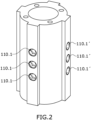
- FIG. 2 shows an enhanced view of a membrane structure (100) implemented in a system suitable for a sand production test, between a first and a second base plate.
- the membrane structure (100) shows two rows of respective trios of radial holes (110.1, 110.1') provided on the watertight outer wall (111) of the main body (110). These radial holes (110.1, 110.1') are configured to house a pin connected to an extensometer, allowing the access of the pin through respective openings provided at the watertight outer wall (111) to the inner wall for measuring the radial deformation of the rock sample.
- the two rows of radial holes (110.1, 110.1') are provided at respective prismatic protrusions which extend from the watertight outer wall (111) of the main body (110), for providing an easier access to the radial holes (110.1, 110.1') from the outside for the insertion of each pin.
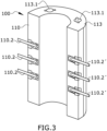
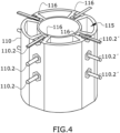
- Figures 3 and 4 show different perspectives of an embodiment of a membrane structure (100), wherein the main body (110) of the membrane structure (100) comprises several rows of radial holes, each one housing a respective pin (110.2, 110.2') of an extensometer.
- figure 3 is intersected by a vertical plane passing through a diameter of the hollow cylindrical shape of the main body (110) of the membrane structure (100), so that only one half of the main body (110) is shown.
- the pins (110.2, 110.2') access through respective openings provided at the watertight outer wall, as well as how each row of pins (110, 110.2') is housed within internal channels extending through corresponding partition walls (116).
- Said channels comprise a distal end located proximate to the rock sample, that is, in a circular section of the main body (110) with a radius slightly greater than the radius of the permeable inner wall.
- figure 3 does not provide details of the internal hollow chambers (115). Only two inlets (113) can be seen provided at the first base (113), each inlet (113) corresponding to a respective internal hollow chamber (115) located within the main body (110). Accordingly, the membrane structure (100) comprises four internal hollow chambers (115), as can be seen in figure 4 .
- figure 4 intersected by a horizontal plane which cuts the uppermost of the three pins (110.2, 110.2') in half, so that additional details are shown regarding how the pins (110.2, 110.2') access the near-rock sample region, through the partition walls (116), for measuring rock sample deformations.
- the distal end of the internal channels is located before a cylindrical section corresponding to the permeable inner wall (112).
- the distal end of the pins (110.2, 110.2') mechanically contact the near-rock sample region of the membrane structure (100) for measuring deformations of the outer surface of the rock sample during the sand production test.
- the openings of the radial holes are provided with respective flexible centering bushings configured to provide the pins (110.2, 110.2') with better alignment and accommodation within the radial holes
- Figure 5 shows a schematic representation of an array of four elastically deformable support structures (208), which are part of four respective extensometers, for a system suitable for a sand production test, according to the embodiments shown in figures 3 and 4 .
- a portion of a structure of a first base plate (201) comprises four column-type support structures (i.e., the elastically deformable support structures (208)), each one disposed so as to face a respective row of the radial housing the pins (110.2, 110.2') shown in figures 3 and 4 .
- each of the elastically deformable support structures (208) of the extensometers comprises a strain gauge (208.1), with each pin (110.2, 110.2') being coupled by one end to said elastically deformable support structure (208) too.
- at least one of the elastically deformable support structures (208) comprises two strain gauges (208.1) arranged according to a half (Wheatstone) bridge configuration.
- at least one of the elastically deformable support structures (208) comprises four strain gauges (208.1) arranged according to a full (Wheatstone) bridge configuration.
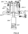
- Figures 6 , 7 and 8 show different configurations of a system (200) suitable for a sand production test according to the invention.
- figure 6 shows a front view of the system (200), intersected by a vertical plane which provides view of internal details of the system (200).
- the system (200) comprises a first base plate (201) onto which the rest of the elements of the system (200) shown are resting.
- a membrane structure (100) according to an embodiment of the first inventive aspect is fixed by its lower (i.e., second) base to the first base plate (201).
- a rock sample (300) provided with a hollow cylinder shape is provided within the internal housing (H) of the membrane structure (100).
- a second base plate (202) is shown resting on the upper (i.e., first) base of the membrane structure (100), closing said housing (H).
- the system (200) of figure 6 comprises the following elements.
- the system (200) comprises a first pump (not shown) for pumping the first fluid into the intermediate space of the casing (not shown) for increasing the first fluid pressure.
- the system (200) comprises a second pump (not shown) for pumping the second fluid.
- the second base plate (202) comprises an input port (202.1) for the intake of the second fluid; and an output port (202.2) which is shown in fluidic communication with an inlet (113.1) of the membrane structure (100) for providing a corresponding internal hollow chamber (115) with a flow of the second fluid.
- the fluid communication between the second pump and the input port (202.1) of the second base plate (202) is established by means of a distribution piping (which is shown in figures 7 and 8 ), such that said distribution piping (202.3) is coupled at a first end with the input port (202.1) of the second base plate (202); and at a second end with a second input port (201.1) provided at first base plate (201).
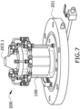
- Figure 7 shows a perspective view of the whole system (200) of figure 6 , wherein the distribution piping (202.3) has been represented.
- the inlet port (201.1) of the first base (201) is connected to a single duct which is connected, downstream of the inlet port (201.1) with a distribution ring comprising a plurality of ducts, each of them coupled by an end with a respective input port (202.1) of the second base plate (202) for establishing fluidic communication.
- each input port (202.1) of the second base plate (202) is in fluidic communication with a respective output port (202.2) which, in the same manner, finally establish fluidic communication with one of the inlets (113.1) provided at the first base (113) of the membrane structure (100) for providing a flow of the second fluid to a corresponding internal hollow chamber (115).
- the system (200) shown in figure 7 comprises a portion of a piston adapted to exert axial force to the second base plate (202) according to the longitudinal direction.
- a truncated cone (203.1) is resting on the second base plate (202) for distributing the pressure, to the second base plate (202), of the axial force exerted by the piston when actuating in operative manner.
- the truncated cone (203.1) is replaced by a cylinder.
- Figure 8 shows a perspective view of the system (200) of figure 7 , intersected by a vertical plane which provides view of internal details of the system (200), and further comprising a collecting compartment (206) provided beneath the membrane structure (100) and configured for receiving both the rock sample (300) particles produced during the sand production test; and the second fluid passing through the rock sample during the sand production test.
- the collecting compartment (206) is provided with a tubular shape, with a lower section of the collection compartment (206) comprising a sand deflector.
- said sand deflector consist of a curved plate fixed to an inner face of the collecting compartment (206) sloping down to the lower base of the collecting compartment (206), so as to permit collapsing sand to fall to the lower sections of the collecting compartment (206) in a controlled manner and try to prevent it from agglomerating at the base in such a way that aggregates are formed.
- the collecting compartment (206) comprises weighing means (207) configured for receiving and weighing the rock sample (300) particles produced during the sand production test and deflected by the sand deflector.
- the weighing means (207) comprise a load cell coupled to a collecting plate located at a lowermost section of the collecting compartment (206).
- Figure 9 shows a perspective view of an embodiment of a system (200) suitable for a sand production test fully assembled in an operative configuration.
- one of the system (200) arrangements shown in figures 6 , 7 or 8 is confined within a casing (205) which is arranged so as to be watertightly fixed on the first base plate (201), defining a pressure chamber within, that is, an intermediate space between the casing (205) and the membrane (100).
- This intermediate space is configured for housing the first fluid supplied by the first pump so as to exert a predetermined hydrostatic pressure on the membrane structure (100).
Landscapes
- Life Sciences & Earth Sciences (AREA)
- Chemical & Material Sciences (AREA)
- Health & Medical Sciences (AREA)
- Immunology (AREA)
- Pathology (AREA)
- General Physics & Mathematics (AREA)
- General Health & Medical Sciences (AREA)
- Biochemistry (AREA)
- Analytical Chemistry (AREA)
- Physics & Mathematics (AREA)
- Engineering & Computer Science (AREA)
- Medicinal Chemistry (AREA)
- Food Science & Technology (AREA)
- Environmental & Geological Engineering (AREA)
- General Life Sciences & Earth Sciences (AREA)
- Remote Sensing (AREA)
- Geology (AREA)
- Dispersion Chemistry (AREA)
- Investigating Strength Of Materials By Application Of Mechanical Stress (AREA)
- Polyurethanes Or Polyureas (AREA)
- Separation Using Semi-Permeable Membranes (AREA)
Claims (15)
- Membranstruktur (100), die für einen Sandproduktionstest einer Gesteinsprobe (300) geeignet ist, die mit einer hohlen Zylinderform versehen ist, die sich entlang einer Längsrichtung erstreckt, wobei die Membranstruktur (100) einen Hauptkörper (110) umfasst, wobei der Hauptkörper (110) Folgendes umfasst:ein Gehäuse (H), das dazu ausgebildet ist, die Gesteinsprobe (300) darin einzuschließen;eine wasserdichte Außenwand (111), die geeignet ist, einem externen hydrostatischen Druck standzuhalten, der von einem ersten Fluid ausgeübt wird, wenn die Membranstruktur (100) in Betrieb ist;eine durchlässige Innenwand (112), die das Gehäuse (H) begrenzt und dazu ausgebildet ist, Druck auf die Gesteinsprobe (300) auszuüben und ein zweites Fluid in die Außenfläche der Gesteinsprobe (300) zu injizieren, wenn die Membranstruktur (100) in Betrieb ist;eine erste Basis (113);eine zweite Basis (114), die der ersten Basis (113) in Längsrichtung gegenüberliegt;dadurch gekennzeichnet, dass der Hauptkörper (110) ferner Folgendes umfasst:wobei
eine Vielzahl von inneren Hohlkammern (115), die sich zwischen der wasserdichten Außenwand (111) und der durchlässigen Innenwand (112) befinden,der Hauptkörper (110) der Membranstruktur (100) eine Vielzahl von Trennwänden (116) umfasst, wobei jede der Vielzahl von Trennwänden (116) dazu ausgebildet ist, zwei benachbarte innere Hohlkammern (115) zu trennen;die erste Basis (113) oder die zweite Basis (114) des Hauptkörpers (110) eine Vielzahl von Einlässen (113.1) umfasst, von denen jeder dazu ausgebildet ist, eine Fluidverbindung zwischen einer der Vielzahl von inneren Hohlkammern (115) und einer externen Quelle des zweiten Fluids herzustellen; undjede der Vielzahl von inneren Hohlkammern (115) eine Vielzahl von starren Teilchen (115.1) umfasst, die den Innenraum jeder Hohlkammer (115) ausfüllen, wobei die Vielzahl von starren Teilchen (115.1) dazu bestimmt sind, den von der Außenwand (111) ausgeübten Außendruck auf die Innenwand (112) zu übertragen, während sie den Durchgang des zweiten Fluids von dem mindestens einen Einlass (113.1) zu der durchlässigen Innenwand (112) erlauben. - Membranstruktur (100) nach Anspruch 1, wobei sich mindestens eine der Vielzahl von inneren Hohlkammern (115) entlang eines kreisförmigen trapezförmigen Abschnitts des Hauptkörpers (110) erstreckt.
- Membranstruktur (100) nach Anspruch 1 oder 2, wobei die durchlässige Innenwand (112) eine Vielzahl von Poren (112.1) umfasst, sodass eine Fluidverbindung zwischen jeder der Vielzahl von inneren Hohlkammern (115) und dem Gehäuse (H) hergestellt wird, das dazu ausgebildet ist, die Gesteinsprobe (300) einzuschließen.
- Membranstruktur (100) nach einem der vorhergehenden Ansprüche, wobei die Vielzahl von inneren Hohlkammern (115) gleichmäßig entlang einer kreisförmigen Bahn um die Längsrichtung verteilt ist.
- Membranstruktur (100) nach einem der vorhergehenden Ansprüche, wobei die Vielzahl von starren Teilchen (115.1) kugelförmige Stahlteilchen sind, die in einem dicht gepackten Zustand gestapelt sind.
- Membranstruktur (100) nach einem der vorhergehenden Ansprüche, wobei mindestens eine innere Hohlkammer (115) ein neben der durchlässigen Innenwand (112) vorgesehenes Filternetz (115.2) umfasst.
- Membranstruktur (100) nach einem der vorhergehenden Ansprüche, wobei der Hauptkörper (110) mindestens ein radiales Loch (110.1) umfasst, das dazu ausgebildet ist, einen mit einem Extensometer verbundenen Stift (110.2) aufzunehmen, was den Zugang des Stifts (110.2) durch eine an der wasserdichten Außenwand (111) vorgesehene Öffnung zu der Innenwand erlaubt, um die radiale Verformung der Probe oder des Gesteins zu messen.
- Membranstruktur (100) nach einem der vorhergehenden Ansprüche und Anspruch 7, wobei sich das radiale Loch (110.1) durch eine Trennwand (116) des Hauptkörpers (110) erstreckt.
- Membranstruktur (100) nach einem der vorhergehenden Ansprüche, wobei der Hauptkörper (110) aus einem elastomeren Polymer besteht.
- System (200), das für einen Sandproduktionstest einer Gesteinsprobe (300) geeignet ist, die mit einer hohlen Zylinderform versehen ist, die sich entlang einer Längsrichtung erstreckt, wobei das System (200) Folgendes umfasst:- eine erste Bodenplatte (201);- eine Membranstruktur (100) nach einem der Ansprüche 1 bis 9, wobei die zweite Basis (114) der Membranstruktur (100) auf der ersten Bodenplatte (201) ruht;- eine zweite Bodenplatte (202), die auf der ersten Basis (113) der Membranstruktur (100) ruht und dazu ausgebildet ist, eine axiale Kraft auf die Membranstruktur (100) und auf die in dem Gehäuse (H) der in Betrieb befindlichen Membranstruktur (100) eingeschlossene Gesteinsprobe (300) auszuüben;- ein Gehäuse (205), das über der ersten Bodenplatte (201) angeordnet ist, wobei das Gehäuse dazu ausgebildet ist, die Membran (100) und die zweite Bodenplatte (202) mit einem Zwischenraum zwischen dem Gehäuse (205) und der Membran (100) aufzunehmen, um das erste Fluid aufzunehmen;- einen Kolben (203), der dazu ausgelegt ist, eine axiale Kraft auf die zweite Bodenplatte (202) in Längsrichtung auszuüben;- eine erste Pumpe zum Pumpen des ersten Fluids;- eine zweite Pumpe zum Pumpen des zweiten Fluids;wobei die zweite Bodenplatte (202) mindestens einen Eingangsanschluss (202.1) für das zweite Fluid und einen Ausgangsanschluss (202.2) für das zweite Fluid umfasst, sodassder Eingangsanschluss (202.1) mit der zweiten Pumpe in Fluidverbindung steht; undder Ausgangsanschluss (202.2) mit dem mindestens einen Einlass (113.1) der Membranstruktur (100) in Fluidverbindung steht und dazu ausgebildet ist, eine Fluidverbindung zwischen der Vielzahl von inneren Hohlkammern (115) und einer externen Quelle des zweiten Fluids herzustellen; undwobei die erste Pumpe mit dem Zwischenraum des Gehäuses (205) in Fluidverbindung steht, um den ersten Fluiddruck zu erhöhen, wobei das erste Fluid mit der wasserdichten Außenwand (111) der Membranstruktur (100) in Wirkverbindung steht.
- System (200) nach Anspruch 10, wobei die Fluidverbindung zwischen der zweiten Pumpe und dem Eingangsanschluss (202.1) der zweiten Bodenplatte (202) mittels einer Verteilungsrohrleitung (202.3) hergestellt wird, sodassdie Verteilungsrohrleitung (202.3) an einem ersten Ende mit dem Eingangsanschluss (202.1) der zweiten Bodenplatte (202) verbunden ist; unddie Verteilungsrohrleitung (202.3) an einem zweiten Ende mit der ersten Bodenplatte (201) verbunden ist;und wobei die erste Bodenplatte (201) ferner einen zweiten Eingangsanschluss (201.1) umfasst, der dazu ausgebildet ist, eine Fluidverbindung zwischen der zweiten Pumpe und dem zweiten Ende der Verteilungsrohrleitung (202.3) herzustellen.
- System (200) nach einem der Ansprüche 10 bis 11, wobei der Kolben (203) mit einem Kegelstumpf (203.1) verbunden ist, der auf der zweiten Bodenplatte (202) ruht und für eine Druckumverteilung der von dem Kolben (203) ausgeübten axialen Kraft auf die zweite Bodenplatte (202) ausgebildet ist, wenn er in Betrieb ist.
- System nach einem der Ansprüche 10 bis 12, das ferner ein Sammelfach (206) umfasst, das unterhalb der Membranstruktur (100) vorgesehen und dazu ausgebildet ist, Folgendes aufzunehmen:- Teilchen einer Gesteinsprobe (300), die während des Sandproduktionstests entstanden sind; und- das zweite Fluid, das während des Sandproduktionstests durch die Gesteinsprobe läuft.
- System (200) nach Anspruch 13, wobei das Sammelfach (206) Wiegemittel (207) umfasst, die dazu ausgebildet sind, die während des Sandproduktionstests entstandenen Teilchen der Gesteinsprobe (300) aufzunehmen und zu wiegen.
- System (200) nach Anspruch 7 und einem der Ansprüche 10 bis 14, wobei die erste Bodenplatte (201) mindestens ein Extensometer umfasst, das wiederum eine elastisch verformbare Stützstruktur (208) umfasst, die dem mindestens einen radialen Loch (110.1) gegenüberliegt, das einen Stift (110.2) aufnimmt, sodass:die elastisch verformbare Stützstruktur (208) einen Dehnungsmessstreifen (208.1) umfasst, undder Stift (110.2) an einem Ende mit der Stützstruktur (208) verbunden ist.
Priority Applications (4)
| Application Number | Priority Date | Filing Date | Title |
|---|---|---|---|
| EP20383147.4A EP4019936B1 (de) | 2020-12-23 | 2020-12-23 | Membranstruktur für sandproduktionstest |
| ES20383147T ES2944884T3 (es) | 2020-12-23 | 2020-12-23 | Estructura de membrana adecuada para una prueba de producción de arena |
| US17/541,470 US11747247B2 (en) | 2020-12-23 | 2021-12-03 | Membrane structure suitable for a sand production test |
| CA3141104A CA3141104A1 (en) | 2020-12-23 | 2021-12-06 | Membrane structure suitable for a sand production test |
Applications Claiming Priority (1)
| Application Number | Priority Date | Filing Date | Title |
|---|---|---|---|
| EP20383147.4A EP4019936B1 (de) | 2020-12-23 | 2020-12-23 | Membranstruktur für sandproduktionstest |
Publications (2)
| Publication Number | Publication Date |
|---|---|
| EP4019936A1 EP4019936A1 (de) | 2022-06-29 |
| EP4019936B1 true EP4019936B1 (de) | 2023-03-29 |
Family
ID=74194482
Family Applications (1)
| Application Number | Title | Priority Date | Filing Date |
|---|---|---|---|
| EP20383147.4A Active EP4019936B1 (de) | 2020-12-23 | 2020-12-23 | Membranstruktur für sandproduktionstest |
Country Status (4)
| Country | Link |
|---|---|
| US (1) | US11747247B2 (de) |
| EP (1) | EP4019936B1 (de) |
| CA (1) | CA3141104A1 (de) |
| ES (1) | ES2944884T3 (de) |
Families Citing this family (5)
| Publication number | Priority date | Publication date | Assignee | Title |
|---|---|---|---|---|
| US12216094B2 (en) * | 2021-08-03 | 2025-02-04 | Illinois Tool Works Inc. | Material testing systems including improved component cooling |
| CN116203211B (zh) * | 2023-01-06 | 2024-03-26 | 哈尔滨工业大学(深圳)(哈尔滨工业大学深圳科技创新研究院) | 一种适用于带导管式橡皮膜的承膜筒装置及应用方法 |
| CN117092012B (zh) * | 2023-10-18 | 2023-12-19 | 华侨大学 | 一种隧道开挖围岩渗水试验装置 |
| CN119064168B (zh) * | 2024-08-28 | 2025-09-09 | 中南大学 | 多场耦合环境透明化模拟的大尺度多功能实验设备及方法 |
| CN120761185B (zh) * | 2025-09-09 | 2025-11-18 | 内蒙古农业大学 | 一种适用于超饱和冻土试样分区控温动态围压加载装置 |
Family Cites Families (6)
| Publication number | Priority date | Publication date | Assignee | Title |
|---|---|---|---|---|
| US20100089124A1 (en) * | 2008-09-26 | 2010-04-15 | North Dakota State University | Integrated porous rigid wall and flexible wall permeability test device for soils |
| US10900945B2 (en) * | 2013-10-21 | 2021-01-26 | Saudi Arabian Oil Company | Tri-axial centrifuge apparatus with electrical sensor, acoustic sensor, and X-ray instrument |
| EP3126620A4 (de) * | 2014-04-04 | 2017-11-29 | Services Pétroliers Schlumberger | Bohrlochzementsimulator |
| US10845291B2 (en) * | 2017-05-16 | 2020-11-24 | King Fahd University Of Petroleum And Minerals | Radial core flooding apparatus and method for analysis of static and/or dynamic properties of reservoir rock |
| CN112284922B (zh) * | 2020-11-11 | 2023-03-31 | 太原理工大学 | 一种煤岩体高温三轴流变及动静组合加载试验装置 |
| CN112880549A (zh) * | 2021-03-22 | 2021-06-01 | 安徽理工大学 | 一种轴向径向一体化三轴引伸计 |
-
2020
- 2020-12-23 EP EP20383147.4A patent/EP4019936B1/de active Active
- 2020-12-23 ES ES20383147T patent/ES2944884T3/es active Active
-
2021
- 2021-12-03 US US17/541,470 patent/US11747247B2/en active Active
- 2021-12-06 CA CA3141104A patent/CA3141104A1/en active Pending
Also Published As
| Publication number | Publication date |
|---|---|
| CA3141104A1 (en) | 2022-06-23 |
| ES2944884T3 (es) | 2023-06-26 |
| EP4019936A1 (de) | 2022-06-29 |
| US20220196528A1 (en) | 2022-06-23 |
| US11747247B2 (en) | 2023-09-05 |
Similar Documents
| Publication | Publication Date | Title |
|---|---|---|
| EP4019936B1 (de) | Membranstruktur für sandproduktionstest | |
| US7552648B2 (en) | Measuring mechanical properties | |
| Ma et al. | Compaction and seepage properties of crushed limestone particle mixture: an experimental investigation for Ordovician karst collapse pillar groundwater inrush | |
| US10197549B2 (en) | Wellbore cement simulator | |
| Chen et al. | Impermeable and mechanical stability of filter cake under different infiltration conditions via CFD-DEM | |
| Kluge et al. | Hydraulic-mechanical properties of microfaults in granitic rock using the Punch-Through Shear test | |
| Bai et al. | Numerical modeling of stress-dependent permeability | |
| AU2013403995B2 (en) | Modular sensed annular well apparatus for cement testing | |
| CN115110931B (zh) | 一种低渗油藏压驱注水增渗程度表征方法 | |
| Altuhafi et al. | The small-strain stiffness of a railway ballast | |
| US11092588B2 (en) | Measurement cell and associated measurement method | |
| KR100442115B1 (ko) | 미고결시료의 저류물성 측정을 위한 코아 고정장치 | |
| CN115614025B (zh) | 一种裂缝穿越海陆过渡相岩性界面偏转角测量装置及方法 | |
| Berntsen et al. | Scale effect in volumetric sand production | |
| CN116087434A (zh) | 测试装置及测试方法 | |
| US11628600B2 (en) | Fabrication method of transparent 3D polydimethylsiloxane devices with polycaprolactone molds | |
| Vahidoddin et al. | An experimental rock mechanics investigation for sand production in oil fields | |
| Riabokon et al. | The mechanism of capillaries hydraulic conductivity evolution under confining pressure: Experimental modelling using 3D-printing approach | |
| Ahmadinejad et al. | Experimental study of the hydro-mechanical response of tight Sarvak carbonates to hydrostatic and deviatoric stress changes | |
| Eskandani et al. | How to model granular soils under high pressure | |
| DeValve et al. | VOID FORMATION DURING PREFORM IMPREGNATION IN LIQUID COMPOSITE MOLDING PROCESSES | |
| CN121410225A (zh) | 一种土工布外包测压管结构淤堵实验方法及装置 | |
| Thompson et al. | An Experimental Technique For The Investigation Of The Flow Of Halite And Sylvinite | |
| Peters et al. | A biaxial consolidation test for anisotropic soils | |
| Yale et al. | Large-scale laboratory testing of the geomechanics of petroleum reservoirs |
Legal Events
| Date | Code | Title | Description |
|---|---|---|---|
| PUAI | Public reference made under article 153(3) epc to a published international application that has entered the european phase |
Free format text: ORIGINAL CODE: 0009012 |
|
| STAA | Information on the status of an ep patent application or granted ep patent |
Free format text: STATUS: THE APPLICATION HAS BEEN PUBLISHED |
|
| AK | Designated contracting states |
Kind code of ref document: A1 Designated state(s): AL AT BE BG CH CY CZ DE DK EE ES FI FR GB GR HR HU IE IS IT LI LT LU LV MC MK MT NL NO PL PT RO RS SE SI SK SM TR |
|
| STAA | Information on the status of an ep patent application or granted ep patent |
Free format text: STATUS: REQUEST FOR EXAMINATION WAS MADE |
|
| 17P | Request for examination filed |
Effective date: 20220803 |
|
| RBV | Designated contracting states (corrected) |
Designated state(s): AL AT BE BG CH CY CZ DE DK EE ES FI FR GB GR HR HU IE IS IT LI LT LU LV MC MK MT NL NO PL PT RO RS SE SI SK SM TR |
|
| GRAP | Despatch of communication of intention to grant a patent |
Free format text: ORIGINAL CODE: EPIDOSNIGR1 |
|
| STAA | Information on the status of an ep patent application or granted ep patent |
Free format text: STATUS: GRANT OF PATENT IS INTENDED |
|
| INTG | Intention to grant announced |
Effective date: 20221017 |
|
| GRAS | Grant fee paid |
Free format text: ORIGINAL CODE: EPIDOSNIGR3 |
|
| GRAA | (expected) grant |
Free format text: ORIGINAL CODE: 0009210 |
|
| STAA | Information on the status of an ep patent application or granted ep patent |
Free format text: STATUS: THE PATENT HAS BEEN GRANTED |
|
| AK | Designated contracting states |
Kind code of ref document: B1 Designated state(s): AL AT BE BG CH CY CZ DE DK EE ES FI FR GB GR HR HU IE IS IT LI LT LU LV MC MK MT NL NO PL PT RO RS SE SI SK SM TR |
|
| REG | Reference to a national code |
Ref country code: CH Ref legal event code: EP |
|
| REG | Reference to a national code |
Ref country code: DE Ref legal event code: R096 Ref document number: 602020009223 Country of ref document: DE |
|
| REG | Reference to a national code |
Ref country code: AT Ref legal event code: REF Ref document number: 1557015 Country of ref document: AT Kind code of ref document: T Effective date: 20230415 |
|
| REG | Reference to a national code |
Ref country code: IE Ref legal event code: FG4D |
|
| REG | Reference to a national code |
Ref country code: NO Ref legal event code: T2 Effective date: 20230329 |
|
| REG | Reference to a national code |
Ref country code: ES Ref legal event code: FG2A Ref document number: 2944884 Country of ref document: ES Kind code of ref document: T3 Effective date: 20230626 |
|
| REG | Reference to a national code |
Ref country code: LT Ref legal event code: MG9D |
|
| PG25 | Lapsed in a contracting state [announced via postgrant information from national office to epo] |
Ref country code: RS Free format text: LAPSE BECAUSE OF FAILURE TO SUBMIT A TRANSLATION OF THE DESCRIPTION OR TO PAY THE FEE WITHIN THE PRESCRIBED TIME-LIMIT Effective date: 20230329 Ref country code: LV Free format text: LAPSE BECAUSE OF FAILURE TO SUBMIT A TRANSLATION OF THE DESCRIPTION OR TO PAY THE FEE WITHIN THE PRESCRIBED TIME-LIMIT Effective date: 20230329 Ref country code: LT Free format text: LAPSE BECAUSE OF FAILURE TO SUBMIT A TRANSLATION OF THE DESCRIPTION OR TO PAY THE FEE WITHIN THE PRESCRIBED TIME-LIMIT Effective date: 20230329 Ref country code: HR Free format text: LAPSE BECAUSE OF FAILURE TO SUBMIT A TRANSLATION OF THE DESCRIPTION OR TO PAY THE FEE WITHIN THE PRESCRIBED TIME-LIMIT Effective date: 20230329 |
|
| REG | Reference to a national code |
Ref country code: NL Ref legal event code: MP Effective date: 20230329 |
|
| REG | Reference to a national code |
Ref country code: AT Ref legal event code: MK05 Ref document number: 1557015 Country of ref document: AT Kind code of ref document: T Effective date: 20230329 |
|
| PG25 | Lapsed in a contracting state [announced via postgrant information from national office to epo] |
Ref country code: SE Free format text: LAPSE BECAUSE OF FAILURE TO SUBMIT A TRANSLATION OF THE DESCRIPTION OR TO PAY THE FEE WITHIN THE PRESCRIBED TIME-LIMIT Effective date: 20230329 Ref country code: NL Free format text: LAPSE BECAUSE OF FAILURE TO SUBMIT A TRANSLATION OF THE DESCRIPTION OR TO PAY THE FEE WITHIN THE PRESCRIBED TIME-LIMIT Effective date: 20230329 Ref country code: GR Free format text: LAPSE BECAUSE OF FAILURE TO SUBMIT A TRANSLATION OF THE DESCRIPTION OR TO PAY THE FEE WITHIN THE PRESCRIBED TIME-LIMIT Effective date: 20230630 Ref country code: FI Free format text: LAPSE BECAUSE OF FAILURE TO SUBMIT A TRANSLATION OF THE DESCRIPTION OR TO PAY THE FEE WITHIN THE PRESCRIBED TIME-LIMIT Effective date: 20230329 |
|
| PG25 | Lapsed in a contracting state [announced via postgrant information from national office to epo] |
Ref country code: SM Free format text: LAPSE BECAUSE OF FAILURE TO SUBMIT A TRANSLATION OF THE DESCRIPTION OR TO PAY THE FEE WITHIN THE PRESCRIBED TIME-LIMIT Effective date: 20230329 Ref country code: RO Free format text: LAPSE BECAUSE OF FAILURE TO SUBMIT A TRANSLATION OF THE DESCRIPTION OR TO PAY THE FEE WITHIN THE PRESCRIBED TIME-LIMIT Effective date: 20230329 Ref country code: PT Free format text: LAPSE BECAUSE OF FAILURE TO SUBMIT A TRANSLATION OF THE DESCRIPTION OR TO PAY THE FEE WITHIN THE PRESCRIBED TIME-LIMIT Effective date: 20230731 Ref country code: EE Free format text: LAPSE BECAUSE OF FAILURE TO SUBMIT A TRANSLATION OF THE DESCRIPTION OR TO PAY THE FEE WITHIN THE PRESCRIBED TIME-LIMIT Effective date: 20230329 Ref country code: AT Free format text: LAPSE BECAUSE OF FAILURE TO SUBMIT A TRANSLATION OF THE DESCRIPTION OR TO PAY THE FEE WITHIN THE PRESCRIBED TIME-LIMIT Effective date: 20230329 |
|
| PG25 | Lapsed in a contracting state [announced via postgrant information from national office to epo] |
Ref country code: SK Free format text: LAPSE BECAUSE OF FAILURE TO SUBMIT A TRANSLATION OF THE DESCRIPTION OR TO PAY THE FEE WITHIN THE PRESCRIBED TIME-LIMIT Effective date: 20230329 Ref country code: PL Free format text: LAPSE BECAUSE OF FAILURE TO SUBMIT A TRANSLATION OF THE DESCRIPTION OR TO PAY THE FEE WITHIN THE PRESCRIBED TIME-LIMIT Effective date: 20230329 Ref country code: IS Free format text: LAPSE BECAUSE OF FAILURE TO SUBMIT A TRANSLATION OF THE DESCRIPTION OR TO PAY THE FEE WITHIN THE PRESCRIBED TIME-LIMIT Effective date: 20230729 |
|
| REG | Reference to a national code |
Ref country code: DE Ref legal event code: R097 Ref document number: 602020009223 Country of ref document: DE |
|
| PG25 | Lapsed in a contracting state [announced via postgrant information from national office to epo] |
Ref country code: DK Free format text: LAPSE BECAUSE OF FAILURE TO SUBMIT A TRANSLATION OF THE DESCRIPTION OR TO PAY THE FEE WITHIN THE PRESCRIBED TIME-LIMIT Effective date: 20230329 Ref country code: CZ Free format text: LAPSE BECAUSE OF FAILURE TO SUBMIT A TRANSLATION OF THE DESCRIPTION OR TO PAY THE FEE WITHIN THE PRESCRIBED TIME-LIMIT Effective date: 20230329 |
|
| PLBE | No opposition filed within time limit |
Free format text: ORIGINAL CODE: 0009261 |
|
| STAA | Information on the status of an ep patent application or granted ep patent |
Free format text: STATUS: NO OPPOSITION FILED WITHIN TIME LIMIT |
|
| 26N | No opposition filed |
Effective date: 20240103 |
|
| PG25 | Lapsed in a contracting state [announced via postgrant information from national office to epo] |
Ref country code: SI Free format text: LAPSE BECAUSE OF FAILURE TO SUBMIT A TRANSLATION OF THE DESCRIPTION OR TO PAY THE FEE WITHIN THE PRESCRIBED TIME-LIMIT Effective date: 20230329 |
|
| PG25 | Lapsed in a contracting state [announced via postgrant information from national office to epo] |
Ref country code: SI Free format text: LAPSE BECAUSE OF FAILURE TO SUBMIT A TRANSLATION OF THE DESCRIPTION OR TO PAY THE FEE WITHIN THE PRESCRIBED TIME-LIMIT Effective date: 20230329 Ref country code: IT Free format text: LAPSE BECAUSE OF FAILURE TO SUBMIT A TRANSLATION OF THE DESCRIPTION OR TO PAY THE FEE WITHIN THE PRESCRIBED TIME-LIMIT Effective date: 20230329 |
|
| REG | Reference to a national code |
Ref country code: DE Ref legal event code: R119 Ref document number: 602020009223 Country of ref document: DE |
|
| REG | Reference to a national code |
Ref country code: CH Ref legal event code: PL |
|
| PG25 | Lapsed in a contracting state [announced via postgrant information from national office to epo] |
Ref country code: LU Free format text: LAPSE BECAUSE OF NON-PAYMENT OF DUE FEES Effective date: 20231223 |
|
| PG25 | Lapsed in a contracting state [announced via postgrant information from national office to epo] |
Ref country code: MC Free format text: LAPSE BECAUSE OF FAILURE TO SUBMIT A TRANSLATION OF THE DESCRIPTION OR TO PAY THE FEE WITHIN THE PRESCRIBED TIME-LIMIT Effective date: 20230329 |
|
| REG | Reference to a national code |
Ref country code: BE Ref legal event code: MM Effective date: 20231231 |
|
| PG25 | Lapsed in a contracting state [announced via postgrant information from national office to epo] |
Ref country code: MC Free format text: LAPSE BECAUSE OF FAILURE TO SUBMIT A TRANSLATION OF THE DESCRIPTION OR TO PAY THE FEE WITHIN THE PRESCRIBED TIME-LIMIT Effective date: 20230329 Ref country code: LU Free format text: LAPSE BECAUSE OF NON-PAYMENT OF DUE FEES Effective date: 20231223 |
|
| REG | Reference to a national code |
Ref country code: IE Ref legal event code: MM4A |
|
| PG25 | Lapsed in a contracting state [announced via postgrant information from national office to epo] |
Ref country code: DE Free format text: LAPSE BECAUSE OF NON-PAYMENT OF DUE FEES Effective date: 20240702 Ref country code: IE Free format text: LAPSE BECAUSE OF NON-PAYMENT OF DUE FEES Effective date: 20231223 |
|
| PG25 | Lapsed in a contracting state [announced via postgrant information from national office to epo] |
Ref country code: BE Free format text: LAPSE BECAUSE OF NON-PAYMENT OF DUE FEES Effective date: 20231231 |
|
| PG25 | Lapsed in a contracting state [announced via postgrant information from national office to epo] |
Ref country code: FR Free format text: LAPSE BECAUSE OF NON-PAYMENT OF DUE FEES Effective date: 20231231 |
|
| PG25 | Lapsed in a contracting state [announced via postgrant information from national office to epo] |
Ref country code: CH Free format text: LAPSE BECAUSE OF NON-PAYMENT OF DUE FEES Effective date: 20231231 |
|
| PG25 | Lapsed in a contracting state [announced via postgrant information from national office to epo] |
Ref country code: IE Free format text: LAPSE BECAUSE OF NON-PAYMENT OF DUE FEES Effective date: 20231223 Ref country code: FR Free format text: LAPSE BECAUSE OF NON-PAYMENT OF DUE FEES Effective date: 20231231 Ref country code: DE Free format text: LAPSE BECAUSE OF NON-PAYMENT OF DUE FEES Effective date: 20240702 Ref country code: CH Free format text: LAPSE BECAUSE OF NON-PAYMENT OF DUE FEES Effective date: 20231231 Ref country code: BE Free format text: LAPSE BECAUSE OF NON-PAYMENT OF DUE FEES Effective date: 20231231 |
|
| PG25 | Lapsed in a contracting state [announced via postgrant information from national office to epo] |
Ref country code: BG Free format text: LAPSE BECAUSE OF FAILURE TO SUBMIT A TRANSLATION OF THE DESCRIPTION OR TO PAY THE FEE WITHIN THE PRESCRIBED TIME-LIMIT Effective date: 20230329 |
|
| PG25 | Lapsed in a contracting state [announced via postgrant information from national office to epo] |
Ref country code: BG Free format text: LAPSE BECAUSE OF FAILURE TO SUBMIT A TRANSLATION OF THE DESCRIPTION OR TO PAY THE FEE WITHIN THE PRESCRIBED TIME-LIMIT Effective date: 20230329 |
|
| PGFP | Annual fee paid to national office [announced via postgrant information from national office to epo] |
Ref country code: ES Payment date: 20250108 Year of fee payment: 5 |
|
| PG25 | Lapsed in a contracting state [announced via postgrant information from national office to epo] |
Ref country code: CY Free format text: LAPSE BECAUSE OF FAILURE TO SUBMIT A TRANSLATION OF THE DESCRIPTION OR TO PAY THE FEE WITHIN THE PRESCRIBED TIME-LIMIT; INVALID AB INITIO Effective date: 20201223 |
|
| PG25 | Lapsed in a contracting state [announced via postgrant information from national office to epo] |
Ref country code: HU Free format text: LAPSE BECAUSE OF FAILURE TO SUBMIT A TRANSLATION OF THE DESCRIPTION OR TO PAY THE FEE WITHIN THE PRESCRIBED TIME-LIMIT; INVALID AB INITIO Effective date: 20201223 |
|
| PG25 | Lapsed in a contracting state [announced via postgrant information from national office to epo] |
Ref country code: TR Free format text: LAPSE BECAUSE OF FAILURE TO SUBMIT A TRANSLATION OF THE DESCRIPTION OR TO PAY THE FEE WITHIN THE PRESCRIBED TIME-LIMIT Effective date: 20230329 |
|
| PGFP | Annual fee paid to national office [announced via postgrant information from national office to epo] |
Ref country code: GB Payment date: 20251229 Year of fee payment: 6 |
|
| PGFP | Annual fee paid to national office [announced via postgrant information from national office to epo] |
Ref country code: NO Payment date: 20251231 Year of fee payment: 6 |