EP4019934B1 - Tragbarer online-in-situ-betastrahlmonitor und überwachungsverfahren - Google Patents
Tragbarer online-in-situ-betastrahlmonitor und überwachungsverfahren Download PDFInfo
- Publication number
- EP4019934B1 EP4019934B1 EP21217290.2A EP21217290A EP4019934B1 EP 4019934 B1 EP4019934 B1 EP 4019934B1 EP 21217290 A EP21217290 A EP 21217290A EP 4019934 B1 EP4019934 B1 EP 4019934B1
- Authority
- EP
- European Patent Office
- Prior art keywords
- filter tape
- pressing
- detector
- gas
- filter
- Prior art date
- Legal status (The legal status is an assumption and is not a legal conclusion. Google has not performed a legal analysis and makes no representation as to the accuracy of the status listed.)
- Active
Links
Images



Classifications
-
- G—PHYSICS
- G01—MEASURING; TESTING
- G01N—INVESTIGATING OR ANALYSING MATERIALS BY DETERMINING THEIR CHEMICAL OR PHYSICAL PROPERTIES
- G01N15/00—Investigating characteristics of particles; Investigating permeability, pore-volume or surface-area of porous materials
- G01N15/06—Investigating concentration of particle suspensions
- G01N15/0606—Investigating concentration of particle suspensions by collecting particles on a support
-
- G—PHYSICS
- G01—MEASURING; TESTING
- G01N—INVESTIGATING OR ANALYSING MATERIALS BY DETERMINING THEIR CHEMICAL OR PHYSICAL PROPERTIES
- G01N15/00—Investigating characteristics of particles; Investigating permeability, pore-volume or surface-area of porous materials
- G01N15/06—Investigating concentration of particle suspensions
- G01N15/0606—Investigating concentration of particle suspensions by collecting particles on a support
- G01N15/0637—Moving support
- G01N15/0643—Moving support of the filter type
-
- G—PHYSICS
- G01—MEASURING; TESTING
- G01N—INVESTIGATING OR ANALYSING MATERIALS BY DETERMINING THEIR CHEMICAL OR PHYSICAL PROPERTIES
- G01N23/00—Investigating or analysing materials by the use of wave or particle radiation, e.g. X-rays or neutrons, not covered by groups G01N3/00 – G01N17/00, G01N21/00 or G01N22/00
- G01N23/02—Investigating or analysing materials by the use of wave or particle radiation, e.g. X-rays or neutrons, not covered by groups G01N3/00 – G01N17/00, G01N21/00 or G01N22/00 by transmitting the radiation through the material
- G01N23/06—Investigating or analysing materials by the use of wave or particle radiation, e.g. X-rays or neutrons, not covered by groups G01N3/00 – G01N17/00, G01N21/00 or G01N22/00 by transmitting the radiation through the material and measuring the absorption
-
- G—PHYSICS
- G01—MEASURING; TESTING
- G01N—INVESTIGATING OR ANALYSING MATERIALS BY DETERMINING THEIR CHEMICAL OR PHYSICAL PROPERTIES
- G01N35/00—Automatic analysis not limited to methods or materials provided for in any single one of groups G01N1/00 - G01N33/00; Handling materials therefor
- G01N35/00009—Automatic analysis not limited to methods or materials provided for in any single one of groups G01N1/00 - G01N33/00; Handling materials therefor provided with a sample supporting tape, e.g. with absorbent zones
-
- G—PHYSICS
- G01—MEASURING; TESTING
- G01N—INVESTIGATING OR ANALYSING MATERIALS BY DETERMINING THEIR CHEMICAL OR PHYSICAL PROPERTIES
- G01N15/00—Investigating characteristics of particles; Investigating permeability, pore-volume or surface-area of porous materials
- G01N15/06—Investigating concentration of particle suspensions
- G01N15/075—Investigating concentration of particle suspensions by optical means
-
- G—PHYSICS
- G01—MEASURING; TESTING
- G01N—INVESTIGATING OR ANALYSING MATERIALS BY DETERMINING THEIR CHEMICAL OR PHYSICAL PROPERTIES
- G01N15/00—Investigating characteristics of particles; Investigating permeability, pore-volume or surface-area of porous materials
- G01N2015/0042—Investigating dispersion of solids
- G01N2015/0046—Investigating dispersion of solids in gas, e.g. smoke
-
- G—PHYSICS
- G01—MEASURING; TESTING
- G01N—INVESTIGATING OR ANALYSING MATERIALS BY DETERMINING THEIR CHEMICAL OR PHYSICAL PROPERTIES
- G01N15/00—Investigating characteristics of particles; Investigating permeability, pore-volume or surface-area of porous materials
- G01N15/06—Investigating concentration of particle suspensions
- G01N2015/0662—Comparing before/after passage through filter
-
- G—PHYSICS
- G01—MEASURING; TESTING
- G01N—INVESTIGATING OR ANALYSING MATERIALS BY DETERMINING THEIR CHEMICAL OR PHYSICAL PROPERTIES
- G01N35/00—Automatic analysis not limited to methods or materials provided for in any single one of groups G01N1/00 - G01N33/00; Handling materials therefor
- G01N35/00009—Automatic analysis not limited to methods or materials provided for in any single one of groups G01N1/00 - G01N33/00; Handling materials therefor provided with a sample supporting tape, e.g. with absorbent zones
- G01N2035/00019—Automatic analysis not limited to methods or materials provided for in any single one of groups G01N1/00 - G01N33/00; Handling materials therefor provided with a sample supporting tape, e.g. with absorbent zones cassette structures
-
- G—PHYSICS
- G01—MEASURING; TESTING
- G01N—INVESTIGATING OR ANALYSING MATERIALS BY DETERMINING THEIR CHEMICAL OR PHYSICAL PROPERTIES
- G01N2223/00—Investigating materials by wave or particle radiation
- G01N2223/03—Investigating materials by wave or particle radiation by transmission
- G01N2223/04—Investigating materials by wave or particle radiation by transmission and measuring absorption
-
- G—PHYSICS
- G01—MEASURING; TESTING
- G01N—INVESTIGATING OR ANALYSING MATERIALS BY DETERMINING THEIR CHEMICAL OR PHYSICAL PROPERTIES
- G01N2223/00—Investigating materials by wave or particle radiation
- G01N2223/10—Different kinds of radiation or particles
- G01N2223/102—Different kinds of radiation or particles beta or electrons
-
- G—PHYSICS
- G01—MEASURING; TESTING
- G01N—INVESTIGATING OR ANALYSING MATERIALS BY DETERMINING THEIR CHEMICAL OR PHYSICAL PROPERTIES
- G01N2223/00—Investigating materials by wave or particle radiation
- G01N2223/60—Specific applications or type of materials
- G01N2223/651—Specific applications or type of materials dust
-
- G—PHYSICS
- G01—MEASURING; TESTING
- G01N—INVESTIGATING OR ANALYSING MATERIALS BY DETERMINING THEIR CHEMICAL OR PHYSICAL PROPERTIES
- G01N33/00—Investigating or analysing materials by specific methods not covered by groups G01N1/00 - G01N31/00
- G01N33/34—Paper
- G01N33/346—Paper sheets
Definitions
- the present disclosure relates to the technical field of detection of particulate matters in gas, and in particular, to a portable on-line in-situ ⁇ -ray monitor and a monitoring method.
- the existing ⁇ -ray-based on-line monitor determines the concentration of ambient dust by measuring the adsorbed radiation quantity of the ambient dust in the atmosphere by using a ⁇ -ray absorption principle. The more rays are adsorbed, the higher the concentration of the ambient dust is; and on the contrary, the less rays are adsorbed, the lower the concentration of the ambient dust is.
- An ambient dust concentration monitor is specially designed for monitoring the ambient dust in ambient air. It is mainly used for the measurement of the concentration of the particulate matters in the fume by an absorption method in the fields of atmosphere quality monitoring networks, mobile monitoring stations, long-term background environment researches, industrial and mining enterprises, scientific research institutes, and the like.
- the existing monitor is not precise enough during filter tape feeding and collecting, and filter tape pressing and the filter tape feeding are prone to errors, which results in inaccurate collected data and large deviation of monitoring results.
- CN 206 920 288 U discloses an automatic device of survey binary channels particulate matter volume concentration, particulate matter separation sampling module is connected with appearance air humidity degree control module, and appearance air humidity degree control module's gas outlet is connected twin -channel sampling and is detected the module, twin -channel sampling detects two tunnel gas outlets of module and is connected with two way constant -current regulation modules respectively, the gas outlet of two way constant -current regulation modules is connected with the sampling pump through the three -way valve.
- CN 206 920 288 U discloses but the concentration by mass of PM 10 and 2.5 particulate matters of PM in the device simultaneous determination atmospheric environment has simple structure, low, long, the quick accuracy of data of cycle of operation of maintenance cost, really realizes online automatic continuous monitor.
- CN 206 920 288 U discloses a beta ray detector and a beta radiation source only needing really to have been realized by the device, both can accomplish the continuous online sampling process of binary channels, have simple structure, low, long, the quick accuracy of data of cycle of operation of maintenance cost, have reduced instrument cost and later maintenance cost, really realize online automatic continuous monitor.
- CN 206 920 288 U discloses the preamble of claim 1.
- CN 210 953 726 U provides a portable atmospheric particulate concentration monitoring mechanism, which comprises a sampling rod and a monitoring host, and the monitoring host comprises a box body;
- the driving device comprises an air port movement unit and a paper tape movement unit; a sealing device; a flow rate control device; a detection device;
- the paper tape moving unit comprises a paper tape feeding unit and a paper tape discharging unit;
- the device comprises a base, a paper tape, a first tape reel, a second tape reel in transmission connection with the first tape reel and a supporting wheel, the paper tape is wound on the first tape reel through the second tape reel, the supporting wheel and the detection device, the distance between the first tape reel and the second tape reel ranges from 5 cm to 15 cm, and the surface of the detection device is provided with an arc surface.
- the portable atmospheric particulate concentration monitoring mechanism provided by CN 210 953 726 U is simple and compact in structure, convenient to carry and small in load.
- CN 210 953 727 U provides an atmospheric particulate concentration monitoring mechanism, which comprises a sampling rod and a monitoring host, and the monitoring host comprises a box body; the driving device comprises an air port movement unit and a paper tape movement unit; a sealing device; a flow rate control device; a detection device; wherein the gas port movement unit comprises a first motor, an eccentric shaft and a lifting unit communicated with the sampling rod; wherein one end of the eccentric shaft is connected with a rotating shaft of the first motor, the other end of the eccentric shaft is connected with the lifting unit, and the first motor drives an air port of the lifting unit to be in contact with and separated from a paper tape of the paper tape movement unit through the eccentric shaft.
- the atmospheric particulate concentration monitoring mechanism provided by CN 210 953 727 U has the advantages of simple and compact structure, no abnormal sound, small load and convenience in measurement.
- KR 2016 0103766 A relates to a fine dust automatic measuring device capable of simultaneously collecting heavy metal samples.
- the fine dust automatic measuring device can automatically measure a concentration of fine dust in air by using beta rays, and can simultaneously extract samples for analyzing components such as heavy metals.
- the fine dust automatic measuring device comprises: a body including an inlet disposed in the upper side thereof to feed a particular flow rate of air including fine dust, including an outlet disposed in the lower side thereof to discharge air having fine dust removed therefrom, and including a flow path for flowing air; a collecting filter sheet disposed in the flow path, and collecting fine dust included in flowing air; a beta ray irradiating unit disposed in the upper side of the collecting filter sheet in the flow path to be separated at particular distance therefrom, and irradiating beta rays toward the collecting filter sheet; and a beta ray detecting unit dispose din the lower side of the collecting filter sheet in the flow path, and detecting beta rays penetrating through the collecting filter sheet.
- an objective of the present disclosure is to provide a portable on-line in-situ ⁇ -ray monitor and a monitoring method as set out in the appended set of claims.
- a portable on-line in-situ ⁇ -ray monitor and a monitoring method include a detection mechanism and a control mechanism electrically connected to each other.
- the detection mechanism includes a filter tape feed device, a filter tape pressing device, a detector, and a gas guide device.
- the gas guide device is arranged in the filter tape pressing device in a penetrating manner to guide a gas to be tested on the test filter tape.
- the filter tape pressing device is arranged right above the detector and is configured for pressing the test filter tape.
- the detector is configured for counting.
- the control mechanism includes a first detector and a second detector.
- the filter tape pressing device is connected to the first detector.
- the filter tape feed device is connected to the second detector.
- the filter tape feed device is configured for storing and moving test filter tape.
- the first detector is configured for detecting a down-pressing situation of the filter tape pressing device and the second detector is configured for detecting a filter tape feeding in-place situation.
- the filter tape pressing device includes a head pressing block and a filter tape pressing holder.
- a head pressing disc is fixedly arranged outside the head pressing block in a sleeving manner.
- An upper end of the head pressing disc is fixedly connected to the filter tape pressing holder through a spring.
- a lower end of the head pressing block is connected to a head pressing membrane.
- An upper end of the pressing head block is connected to a head pressing gas pipe.
- the bottom of the pressing head gas pipe is fixed to an upper end of the filter tape pressing holder through a head pressing seat.
- a gas guide chamber is formed in the head pressing block.
- An end cover is fixed to the bottom of the head pressing block and forms a gas outlet at the bottom of the head pressing block.
- the gas guide device is fixed to the inner side of the end cover. The gas guide device and the gas outlet are arranged coaxially.
- the detector includes a detecting frame.
- a head pressing plate is fixed to the top of the detecting frame.
- a detecting hole is formed at a position, fixedly position where the head pressing plate is fixedly connected to the detecting frame.
- a detector is fixed coaxially to a lower end of the detecting hole.
- the control mechanism includes a main control configured to realize overall control of the monitor.
- the main control panel is connected to a drive group through a relay and the main control panel controls the gas pump to work through the relay.
- the drive group comprises a filter tape drive motor, a flow rate control motor, and a filter tape pressing drive motor.
- the filter tape feed device comprises a primary filter tape belt pulley, a secondary filter tape belt pulley, and two limiting wheels, the primary filter tape belt pulley is connected to a filter tape drive motor; and the filter tape drive motor drives the primary filter tape belt pulley to rotate to feed filter tape.
- the flow rate control motor controls the overall gas inlet amount of the monitor.
- the main control panel controls the flow rate control motor to work through the relay so as to drive a regulating valve to work.
- the filter tape pressing drive motor is fixed to a mounting plate through a filter tape pressing motor frame and the filter tape pressing drive motor works so that the pressing block of the filter tape pressing device performs an operation of pressing the filter tape or lifting up the filter tape.
- An output shaft of the filter tape pressing drive motor is connected to a cam, a side of the cam is connected to the head pressing disc and the cam rotates under the driving of the filter tape pressing drive motor.
- the output shaft of the filter tape pressing drive motor is also fixedly connected to the cam through the first detector.
- a mounting plate is fixed between the detecting mechanism and the control mechanism.
- a connecting hole is formed in the position, corresponding to the gas outlet of the detecting frame, of the mounting plate.
- the connecting hole is connected to a gas guide pipe.
- the other end of the gas guide pipe is connected to a flow regulating device.
- the flow regulating device includes a flowmeter. The flowmeter is connected between the connecting hole and the regulating valve through the gas guide pipe, and the other end of the regulating valve is connected to a gas pump.
- the mounting plate is fixedly arranged in the middle of a box body.
- a collecting mechanism is fixedly arranged on the box body.
- a portable on-line in-situ ⁇ -ray monitoring method includes the following steps:
- the present disclosure has the following beneficial effects.
- the filter tape pressing device is connected to the first detector.
- the head pressing block is also connected to the filter tape pressing drive motor through the cam, so that the head pressing block can be pressed down or lifted up very well, and the sealing property during filter tape pressing and smooth filter tape feeding after lifting up the head pressing block can be ensured.
- the flow regulating device is also arranged, and constant flow sampling is realized by the control mechanism, which further ensures the measurement accuracy.
- the mounting plate is arranged reasonably, and is mounted surface by surface according to functions, which ensures the performance, meanwhile, saves the space, reduces the size, and is portable.
- a component when a component is described as being “fixed” to another component, it may be directly on the other component, or there may be a component therebetween.
- a component When a component is regarded as being “connected” to the other component, it may be directly connected to the other component, or there may be a component therebetween.
- a component When a component is regarded as being “arranged” on the other component, it may be directly arranged on the other component, or there may be a component therebetween.
- the terms “vertical”, “horizontal”, “left”, “right”, and similar expressions used herein are merely for the purpose of illustration.
- a preferred implementation manner of the present disclosure provides a portable on-line in-situ ⁇ -ray monitor, which mainly determines the concentration of ambient dust by measuring the adsorbed radiation quantity of the ambient dust in the atmosphere by using a ⁇ -ray absorption principle.
- Ambient dust collection and detection are set in the same channel, which avoids an error caused by feeding filter tape for a plurality of times.
- An in-place detection device is arranged on each of a filter tape feed device 1 and a filter tape pressing device 2, so as to ensure the accuracy of filter tape feeding and filter tape pressing and avoid an error.
- a flow regulating device is also arranged to perform constant flow sampling, which ensures the measurement accuracy.
- the monitor mainly includes a detecting mechanism and a control mechanism electrically connected to each other.
- the control mechanism controls the detecting mechanism to detect.
- the detection mechanism and the control mechanism are respectively fixed to a front surface and a back surface of a mounting plate 100.
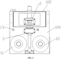
- the detecting mechanism includes the filter tape feed device 1, the filter tape pressing device 2, a detector 3, and a gas guide device 4.
- the gas guide device 4 is arranged in the filter tape pressing device 2 in a penetrating manner.
- the filter tape pressing device 2 is arranged right above the detector 3.
- the control mechanism includes a first detector 5 and a second detector 6.
- the filter tape pressing device 2 is connected to the first detector 5.
- the filter tape feed device 1 is connected to the second detector 6.
- the filter tape feed device 1 is fixed below the mounting plate 100.
- the filter tape feed device 1 is used for storing and moving test filter tape.
- a second detector 6 connected to the filter tape feed device 1 is mainly used for detecting a filter tape feeding in-place situation.
- the filter tape pressing device 2 is used for pressing the test filter tape.
- the first detector 5 is used for detecting a down-pressing situation of the filter tape pressing device 2.
- the gas guide device 4 is arranged in the filter tape pressing device 2 to guide a gas to be tested on the test filter tape.
- the detector 3 is fixed right below the filter tape pressing device 2, and is used for collecting particulate matters in the ambient dust on the test filter tape.
- the whole process is controlled by a control device to automatically realize filter tape feeding, filter tape pressing, gas introducing, and collecting, and the concentration of ambient dust in the atmosphere is obtained through the processing of the control mechanism.
- the filter tape pressing device 2 and the detector 3 are arranged coaxially, so that the collecting can be completed by feeding filter tape once.
- the first detector 5 and the second detector 6 detect the situations of the filter tape pressing device 2 and the filter tape feed device 1 in real time, and sends the situations to the control mechanism, which avoids errors caused by excessive or too little filter tape feeding or not pressing down or lifting up the filter tape pressing device 2 during the process.
- the whole process is controllable and can be performed smoothly. Meanwhile, the test filter tape is tightly pressed through the filter tape pressing device 2, which avoids inaccuracy of the collected data caused by the diffusion of the gas to be tested.
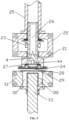
- the filter tape pressing device 2 includes a head pressing block 21 and a filter tape pressing holder 22.
- the filter tape pressing holder 22 is fixed to the mounting plate 100.
- a head pressing disc 23 is arranged outside the head pressing block 21 in a sleeving manner. An upper end of the head pressing disc 23 is fixedly connected to the filter tape pressing holder 22 through a spring.
- a lower end of the head pressing block 21 is connected to a head pressing membrane 24.
- An upper end of the head pressing block is connected to a head pressing gas pipe 25.
- the bottom of the pressing head gas pipe 25 is fixed to an upper end of the filter tape pressing holder 22 through a head pressing seat.
- a gas guide chamber 26 is formed in the head pressing block 21.
- An end cover 27 is fixed to the position, where a gas outlet 28 is formed, at the bottom of the head pressing block 21.
- the gas guide device 4 is fixed to the inner side of the end cover 27.
- the gas guide device 4 and the gas outlet 28 are arranged coaxially.
- the filter tape pressing holder 22 is fixed to the middle of the mounting plate 100.
- the head pressing block 21 is arranged in the filter tape pressing holder 22 in a penetrating manner.
- the head pressing disc 23 is fixed to the outer side of the part, located in the filter tape pressing holder 22, of the head pressing block 21.
- An upper end of the head pressing disc 23 is fixedly connected to the filter tape pressing holder 22 through the spring, so that the head pressing block 21 is driven to move up and down for a certain distance by the head pressing disc 23 under the driving of an external force, thereby facilitating the movement of the test filter tape below the head pressing block 21.
- a gas guide chamber 26 is formed in the head pressing block 21.
- the gas to be tested enters the gas guide chamber 26 through the pressing head gas pipe 25 connected above, comes out from the gas outlet 28 after passing through the gas guide device 4 in the gas guide chamber 26, reaches filter tape to be tested below, and passes through the filter tape to be tested to remain particulate matters on the filter tape to be tested.
- the gas guide device 4 includes a first gas guide component 41 and a second gas guide component 42.
- the first gas guide component 41 is in an inverted conical shape
- the second gas guide component 42 is in a semicircular shape.
- a connecting edge is fixed to the outer sides of the first gas guide component 41 and the second gas guide component 42.
- a diversion port 43 is formed in the inner side of the connecting edge, and is used for the circulating of the gas to be tested. Such arrangement has strong guidance to the gas to be tested, so that all gas can be collected to the gas outlet 28.
- a placement chamber 44 is formed in the first gas guide component 41 and the second gas guide component 42.
- a ⁇ -ray emitter is placed in the placement chamber 44.
- the ⁇ -ray emitter directly faces the gas outlet 28 below. After the collecting of the filter tape to be tested is completed, a beam emitted by the ⁇ -ray emitter is received by the detector 3 below after passing through the filter tape to be tested, and is transmitted to the control mechanism, so as to complete the collecting of data.
- the detector 3 includes a detecting frame 31.
- the detecting frame 31 is fixed to the mounting plate 100.
- a head pressing plate 29 is fixed to the top of the detecting frame 31.
- a detecting hole 32 is formed in a position where the head pressing plate 29 is fixedly connected to the detecting frame 31.
- a detector 33 is fixed coaxially to a lower end of the detecting hole 32.
- the filter tape feed device 1 includes a primary filter tape belt pulley 11, a secondary filter tape belt pulley 12, and two limiting wheels 13.
- the primary filter tape belt pulley 11 is connected to a filter tape drive motor 72.
- the limiting wheel 13 close to the primary filter tape belt pulley 11 is connected to the second detector 6.
- the second detector 6 includes a second limiting piece 61 and a second limit switch 62.
- the second limiting piece 61 and the second limit switch 62 are fixedly arranged on a back surface of the mounting plate 100, correspond to the limiting wheels 13, and are used for detecting a rotating angle of the limiting wheels 13 so as to confirm a filter tape feeding situation.
- the primary filter tape belt pulley 11 and the secondary filter tape belt pulley 12 are respectively arranged on two sides of the detector 3.
- the filter tape to be tested is connected from the primary filter tape belt pulley 11 into the secondary filter tape belt pulley 12 after passing through the first limiting wheel 13, the head pressing plate 29, and the second limiting wheel 13.
- the primary filter tape belt pulley 11 rotates under the driving of the filter tape drive motor 72, so as to drive the filter tape to be tested to move.
- the head pressing block 21 is pressed down to be in contact with the head pressing plate 29, so as to fix the filter tape to be tested, and then collecting is performed. After the collecting is performed for 20 to 50 minutes, the detector 33 performs counting to complete the collecting of atmosphere particulate matter data, and the atmosphere particulate matter data is transmitted to the control mechanism.
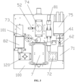
- the control mechanism includes a main control panel 7.
- the main control panel 7 realizes overall control of the system.
- the main control panel 7 is connected to a drive group through a relay 71.
- the drive group includes the filter tape drive motor 72, a flow rate control motor 73, and a filter tape pressing drive motor 74.
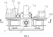
- the filter tape pressing drive motor 74 is fixed to the mounting plate 100 through a filter tape pressing motor frame 741, and corresponds to the head pressing block 21.
- both the first detector 5 and the second detector 6 are connected to the main control panel 7.
- the collected signal is transmitted to the main control panel 7.
- the main control panel 7 determines whether to perform a next operation instruction according to an input signal.
- the main control panel 7 sends a signal to the relay 71, so that the corresponding relay 71 is sucked to enable the drive group connected to the relay 71 to work, i.e., the filter tape drive motor 72 drives the primary filter tape belt pulley 11 to rotate to feed filter tape, or the flow rate control motor 73 control the overall gas inlet amount of the system, or the filter tape pressing drive motor 74 works, so that the filter tape pressing device 2 performs an operation of pressing the filter tape or lifting up the filter tape.
- an output shaft of the filter tape pressing drive motor 74 is fixedly to a cam 742 through the first detector 5.
- an output shaft of the filter tape pressing drive motor 74 is connected to the cam 742.
- a side of the cam 742 is connected to the head pressing disc 23.
- the cam 742 rotates under the driving of the filter tape pressing drive motor 74.
- the head pressing disc 23 is jacked up, so that the head pressing block 21 moves upward to be separated from the test filter tape, thereby facilitating the movement of the test filter tape.
- the cam 742 rotates to the other side, the head pressing disc 23 moves downward under the action of the spring, so that the head pressing block 21 is pressed down to be in contact with the test filter tape, thereby performing collecting work.
- the first detector 5 includes a first head pressing limiting piece 51, and a first limit switch 52 is fixed next to the filter tape pressing drive motor 74.
- the first head pressing limiting piece 51 is matched with the first limit switch 52 to detect an output rotating angle of the filter tape pressing drive motor 74, which ensures that a rotating direction of the cam 742 in place, thereby ensuring that the head pressing block 21 is pressed down or lifted up in place.
- a connecting hole 101 is formed in the position, corresponding to the gas outlet of the detecting frame 31, of the mounting plate 100.
- the connecting hole 101 is connected to a gas guide pipe.
- the other end of the gas guide pipe is connected to a flow regulating device.
- the flow regulating device includes a flowmeter 81.
- the flowmeter 81 is connected between the connecting hole 101 and the regulating valve 82 through the gas guide pipe, and the other end of the regulating valve 82 is connected to a gas pump 83.
- the main control panel 7 controls the flow rate control motor 73 to work through the relay 71, so as to drive the regulating valve 82 to work to control the gas flow to be kept in a constant interval, thereby ensuring the measurement accuracy.
- the mounting plate 100 is fixedly arranged in the middle of a box body, and a collecting mechanism is fixedly arranged on the box body.
- the display panel is connected to the main control panel 7, and is used for displaying collected data and the like, which is convenient for personnel to view on site.
- the collecting mechanism includes a temperature and humidity collector 90, a wind speed collector 91, and a wind direction collector 92.
- the collecting mechanism is connected to the main control panel 7, and sends to the collected data to the main control panel 7.
- the display panel, the detector 3, and the filter tape feed device 1 are mounted on the front surface of the mounting plate 100 in sequence from top to bottom.
- the filter tape pressing device 2 is fixed below the display panel.
- the flow rate control motor 73, the filter tape pressing drive motor 74, the flowmeter 81, and a power supply 75 are fixed to the back surface of the mounting plate 100 in sequence from top to bottom and from left to right.
- the regulating valve 82 is connected below the flow rate control motor 73.
- the connecting hole 101 is formed below the filter tape pressing drive motor 74.
- the second detector 6 is fixed below the power supply 75.
- a secondary filter tape belt pulley mounting frame 120 is fixed below the regulating valve 82.
- the main control panel 7 is fixed below the connecting hole 101.
- the filter tape drive motor 72 is fixed to the right side of the main control panel 7.
- the relay 71 is fixed to the right side of the filter tape drive motor 72.
- the main control panel 7 controls the filter tape pressing drive motor 74 to work through the relay 71.
- the output shaft of the filter tape pressing drive motor 74 rotates to drive the cam 742 to rotate.
- the convex edge of the cam 742 is in contact with the head pressing disc 23 to jack the head pressing disc 23 up, so that the head pressing block 21 is lifted up.
- the main control panel 7 controls the filter tape drive motor 72 to drive the primary filter tape belt pulley 11 to rotate a certain angle to feed filter tape, and the filter tape to be tested drives the limit wheels 13 to rotate.
- a second limit switch 62 When a second limit switch 62 returns a signal to the main control panel 7, it indicates that the filter tape to be tested is in place, and then, the main control panel 7 controls the detector 3 to perform initial counting, and data of blank filter tape to be tested is recorded and is sent to the main control panel 7 for storing. Then, the main control panel 7 controls the filter tape pressing drive motor 74 to work. The convex edge of the cam 742 leaves the head pressing disc 23. The head pressing disc 23 moves downward under the action of the spring to drive the head pressing block 21 to move downward to press the filter tape to be tested.
- the first limit switch 52 returns a signal to the main control panel 7.
- the main control panel 7 controls the gas pump 83 to work after receiving the signal.
- the gas to be tested is pumped, and gas to be tested passes through the head pressing block 21 and passes through the filter tape to be tested. Particulate matters in the ambient dust therein remain on the filter tape to be tested.
- the main control panel 7 controls the gas pump 83 to stop working.
- the filter tape pressing drive motor 74 works, the head pressing disc 23 drives the head pressing block 21 to be lifted up by rotating the cam 742. Then, the beam emitted by the ⁇ -ray emitter is received by the detector 33 after passing through the filter tape to be tested.
- the detector 33 sends collected results to the main control panel 7.
- the main control panel 7 performs a logarithmic operation on the received data and initial data in combination with the temperature and humidity data collected by the temperature and humidity collector 90. Finally, the concentration of the particulate matters in the atmosphere is obtained.
- the main control panel 7 controls the filter tape drive motor 72 to work to move away the used filter tape to be tested, and then a round of collecting and detecting is performed.
Landscapes
- Chemical & Material Sciences (AREA)
- Biochemistry (AREA)
- Physics & Mathematics (AREA)
- Health & Medical Sciences (AREA)
- Life Sciences & Earth Sciences (AREA)
- Analytical Chemistry (AREA)
- General Health & Medical Sciences (AREA)
- General Physics & Mathematics (AREA)
- Immunology (AREA)
- Pathology (AREA)
- Dispersion Chemistry (AREA)
- Sampling And Sample Adjustment (AREA)
- Analysing Materials By The Use Of Radiation (AREA)
- Measurement Of Radiation (AREA)
Claims (8)
- Tragbarer online-in-situ-β-Strahlmonitor, der einen Erfassungsmechanismus und einen Steuermechanismus umfasst, die elektrisch miteinander verbunden sind, wobei der Erfassungsmechanismus eine Filterbandzufuhrvorrichtung (1), eine Filterbandpressvorrichtung (2), einen Detektor (3) und eine Gasführungsvorrichtung (4) umfasst; die Gasführungsvorrichtung (4) in der Filterbandpressvorrichtung (2) durchdringend ausgelegt ist, um ein zu prüfendes Gas auf das Testfilterband zu führen; die Filterbandpressvorrichtung (2) direkt über dem Detektor (3) angeordnet und zum Pressen des Testfilterbandes ausgelegt ist; der Detektor (3) zum Zählen konfiguriert ist; der Kontrollmechanismus einen ersten Detektor (5) und einen zweiten Detektor (6) umfasst; die Filterbandpressvorrichtung (2) mit dem ersten Detektor (5) verbunden ist; und die Filterbandzufuhrvorrichtung (1) mit dem zweiten Detektor (6) verbunden ist, die Filterbandzufuhrvorrichtung (1) zum Speichern und Bewegen von Testfilterband konfiguriert ist; der erste Detektor (5) dafür konfiguriert ist, eine Situation des Herunterdrückens der Filterbandpressvorrichtung (2) zu erfassen, und der zweite Detektor (6) dafür konfiguriert ist, eine Situation der Zuführung des Filterbandes an Ort und Stelle zu erfassen;
wobei der Monitor dadurch gekennzeichnet ist, dass:die Filterbandpressvorrichtung (2) einen Kopfpressblock (21) und einen Filterbandpresshalter (22) umfasst; eine Kopfpressscheibe (23) fest außerhalb des Kopfpressblocks (21) in einer hülsenartigen Weise ausgelegt ist; und ein oberes Ende der Kopfpressscheibe (23) fest mit dem Filterbandpresshalter (22) durch eine Feder verbunden ist; undein unteres Ende des Kopfpressblocks (21) mit einer Kopfpressmembran (24) verbunden ist; ein oberes Ende des Kopfpressblocks (21) mit einem Kopfpressgasrohr (25) verbunden ist; und das untere Ende des Kopfpressgasrohrs (25) mit einem oberen Ende des Filterbandpresshalters (22) durch einen Kopfpresssitz verbunden ist. - Tragbarer online-in-situ-β-Strahlmonitor nach Anspruch 1, wobei eine Gasleitkammer (26) in dem Kopfpressblock (21) gebildet ist; eine Endabdeckung (27) an der Unterseite des Kopfpressblocks (21) befestigt ist und einen Gasauslass (28) an der Unterseite des Kopfpressblocks (21) bildet; die Gasführungsvorrichtung (4) an der Innenseite der Endabdeckung (27) befestigt ist; und die Gasführungsvorrichtung (4) und der Gasauslass (28) koaxial ausgelegt sind.
- Tragbarer online-in-situ-β-Strahlmonitor nach Anspruch 2, wobei der Detektor (3) einen Erfassungsrahmen (31) umfasst; eine Kopfdruckplatte (29) an der Oberseite des Erfassungsrahmens (31) befestigt ist; ein Erfassungsloch (32) an einer Position gebildet ist, an der die Kopfpressplatte (29) fest mit dem Erfassungsrahmen (31) verbunden ist; und ein Detektor (33) koaxial zu einem unteren Ende des Erfassungslochs (32) befestigt ist.
- Tragbarer online-in-situ-β-Strahlmonitor nach Anspruch 2, wobei der Steuermechanismus ein Hauptbedienfeld (7) umfasst, das dafür konfiguriert ist, die Gesamtsteuerung des Monitors zu realisieren; das Hauptbedienfeld (7) über ein Relais (71) mit einer Antriebsgruppe verbunden ist und das Hauptbedienfeld (7) die Gaspumpe (83) steuert, um über das Relais (71) zu arbeiten; die Antriebsgruppe einen Filterbandantriebsmotor (72), einen Durchflussmengensteuermotor (73) und einen Filterbandpressantriebsmotor (74) umfasst; und die Filterbandzufuhrvorrichtung (1) eine primäre Filterbandriemenscheibe (11), eine sekundäre Filterbandriemenscheibe (12) und zwei Begrenzungsräder (13) umfasst, wobei die primäre Filterbandriemenscheibe (11) mit einem Filterbandantriebsmotor (72) verbunden ist; und der Filterbandantriebsmotor (74) die primäre Filterbandriemenscheibe (11) antreibt, um sich zu drehen, um das Zufuhrfilterband zu drehen; der Durchflussmengensteuermotor (73) die Gesamtgaseinlassmenge des Monitors steuert, und das Hauptsteuerpult (11) den Durchflussmengensteuermotor (73) steuert, um über das Relais (71) zu arbeiten, um ein Regelventil (82) zu betreiben; und der Filterbandpressantriebsmotor (74) durch einen Rahmen (741) für den Motor zum Pressen des Filterbandes an einer Montageplatte (100) befestigt ist, und der Filterbandpressantriebsmotor (74) so arbeitet, dass der Pressblock (21) der Filterbandpressvorrichtung (2) eine Operation zum Pressen des Filterbandes oder zum Anheben des Filterbandes durchführt; eine Ausgangswelle des Filterbandpressantriebsmotors (74) mit einem Nocken (742) verbunden ist; eine Seite des Nockens (742) mit der Kopfpressscheibe (23) verbunden ist; und sich der Nocken (742) unter dem Antrieb des Filterbandpressantriebsmotors (74) dreht.
- Tragbarer online-in-situ-β-Strahlmonitor nach Anspruch 4, wobei die Ausgangswelle des Filterbandantriebsmotors (74) über den ersten Detektor (5) auch fest mit der Nocke (742) verbunden ist.
- Tragbarer online-in-situ-β-Strahlmonitor nach Anspruch 3, wobei eine Montageplatte (100) zwischen dem Erfassungsmechanismus und dem Steuermechanismus befestigt ist; ein Verbindungsloch (101) in der Position, die einem Gasauslass des Erfassungsrahmens (31) entspricht, der Montageplatte (100) gebildet ist; das Verbindungsloch (101) mit einem Gasführungsrohr verbunden ist; das andere Ende des Gasführungsrohrs mit einer Durchflussregulierungsvorrichtung verbunden ist; die Durchflussregulierungsvorrichtung einen Durchflussmesser (81) umfasst; und der Durchflussmesser (81) zwischen der Verbindungsöffnung (101) und einem Regulierventil (82) durch das Gasführungsrohr verbunden ist, und das andere Ende des Regulierventils (82) mit einer Gaspumpe (83) verbunden ist.
- Tragbarer online-in-situ-β-Strahlmonitor nach Anspruch 6, wobei die Montageplatte (100) fest in der Mitte eines Gehäusekörpers ausgelegt ist; und ein Auffangmechanismus fest auf dem Gehäusekörper ausgelegt ist.
- Überwachungsverfahren des tragbaren online-in-situ-β-Strahlmonitors, wobei das Überwachungsverfahren durch den tragbaren online-in-situ-β-Strahlmonitor nach einem der Ansprüche 1 bis 7 implementiert wird und folgende Schritte umfasst:S1: Anheben der Filterbandpressvorrichtung (2), Bewegen des Testfilterbandes durch die Filterbandzufuhrvorrichtung (1) und Durchführen einer ersten Zählung durch den Detektor (3);S2: nach Beendigung des Zählens, Herunterdrücken der Filterbandpressvorrichtung (2), Einleiten eines zu prüfenden Gases durch die Gasführungsvorrichtung (4) und Durchführen des Auffangens;S3: nach Beendigung des Sammelns, Anheben der Filterbandpressvorrichtung (2) und Durchführen der Sammelzählung durch den Detektor (3); undS4: nach Beendigung des Zählens, Einlegen eines neuen Testfilterbandes mit Hilfe der Filterbandzufuhrvorrichtung (1) und Durchführen der nächsten Sammelrunde.
Applications Claiming Priority (1)
| Application Number | Priority Date | Filing Date | Title |
|---|---|---|---|
| CN202011544330.9A CN112730179B (zh) | 2020-12-23 | 2020-12-23 | 一种便携式β射线原位在线监测仪及监测方法 |
Publications (3)
| Publication Number | Publication Date |
|---|---|
| EP4019934A1 EP4019934A1 (de) | 2022-06-29 |
| EP4019934B1 true EP4019934B1 (de) | 2024-10-16 |
| EP4019934C0 EP4019934C0 (de) | 2024-10-16 |
Family
ID=75604966
Family Applications (1)
| Application Number | Title | Priority Date | Filing Date |
|---|---|---|---|
| EP21217290.2A Active EP4019934B1 (de) | 2020-12-23 | 2021-12-23 | Tragbarer online-in-situ-betastrahlmonitor und überwachungsverfahren |
Country Status (2)
| Country | Link |
|---|---|
| EP (1) | EP4019934B1 (de) |
| CN (1) | CN112730179B (de) |
Families Citing this family (8)
| Publication number | Priority date | Publication date | Assignee | Title |
|---|---|---|---|---|
| CN113588357B (zh) * | 2021-08-04 | 2024-05-03 | 上海中科新核智能科技有限公司 | 一种放射性气溶胶自动走纸取样和测量装置 |
| KR102600764B1 (ko) * | 2021-10-26 | 2023-11-10 | 주식회사 엑스엘 | 베타선 발생 모듈의 위치가 가변되는 미세먼지 측정 장치 |
| CN113797859A (zh) * | 2021-11-02 | 2021-12-17 | 上海穆帆汽车技术有限公司 | 一种新型盐雾气溶胶发生装置 |
| CN115711834B (zh) * | 2022-09-21 | 2025-08-01 | 天津智易时代科技发展有限公司 | β射线法颗粒物监测设备 |
| CN115575431B (zh) * | 2022-10-12 | 2023-11-21 | 嘉泰检验认证有限公司 | 一种产品环保性检测用的检测仪及检测方法 |
| CN116148150A (zh) * | 2023-03-22 | 2023-05-23 | 安徽庆宇光电科技有限公司 | 空气颗粒物浓度检测装置 |
| CN117740849B (zh) * | 2024-02-19 | 2024-05-28 | 天津美腾科技股份有限公司 | 一种物料整形装置及矿浆灰分仪 |
| CN118624876B (zh) * | 2024-06-27 | 2024-11-19 | 山东三竹数字科技有限公司 | 一种新型自动检测纺织原料质量设备 |
Citations (1)
| Publication number | Priority date | Publication date | Assignee | Title |
|---|---|---|---|---|
| CN109254316A (zh) * | 2018-10-16 | 2019-01-22 | 陕西卫峰核电子有限公司 | 一种核电站气溶胶连续辐射监测装置 |
Family Cites Families (23)
| Publication number | Priority date | Publication date | Assignee | Title |
|---|---|---|---|---|
| US6055052A (en) * | 1998-01-26 | 2000-04-25 | Mie Corporation | System for, and method of, monitoring airborne particulate, including particulate of the PM2.5 class |
| CN2548153Y (zh) * | 2002-06-26 | 2003-04-30 | 张强 | β射线颗粒物烟尘排放连续监测仪 |
| CN101122556B (zh) * | 2007-05-29 | 2010-09-01 | 合肥霍金光电科技有限公司 | 大气颗粒物中碳黑气溶胶的质量浓度监测仪及监测方法 |
| CN102841044A (zh) * | 2012-09-11 | 2012-12-26 | 北京汇丰隆生物科技发展有限公司 | 一种β射线大气颗粒物监测仪及其监测方法 |
| CN202814844U (zh) * | 2012-10-12 | 2013-03-20 | 河北先河环保科技股份有限公司 | 一种颗粒物检测平台装置 |
| CN105346269A (zh) * | 2014-08-22 | 2016-02-24 | 西安优庆商贸有限公司 | 一种可以任意增加打印宽度的电脑打印机 |
| KR101678175B1 (ko) * | 2015-02-25 | 2016-11-21 | (주)켄텍 | 중금속 시료 포집이 동시 가능한 미세먼지 자동 측정 장치 |
| CN205483936U (zh) * | 2016-03-17 | 2016-08-17 | 佛山市南华仪器股份有限公司 | 滤纸式颗粒物检测的走纸机构 |
| CN107219155A (zh) * | 2017-05-31 | 2017-09-29 | 青岛众瑞智能仪器有限公司 | 一种自动测定双通道颗粒物质量浓度的装置 |
| CN107917862B (zh) * | 2017-12-29 | 2020-08-14 | 安徽蓝盾光电子股份有限公司 | 一种具有自动预警功能的Beta射线法颗粒物监测装置 |
| CN108303356A (zh) * | 2017-12-29 | 2018-07-20 | 安徽蓝盾光电子股份有限公司 | 一种大气颗粒物监测仪 |
| CN207964559U (zh) * | 2018-03-20 | 2018-10-12 | 青岛众瑞智能仪器有限公司 | 一种走纸机构整体移动式双工位颗粒物监测装置 |
| CN208969246U (zh) * | 2018-10-16 | 2019-06-11 | 陕西卫峰核电子有限公司 | 一种新型气溶胶符合探测器结构 |
| CN209117532U (zh) * | 2018-11-20 | 2019-07-16 | 天津智易时代科技发展有限公司 | 一种车载扬尘在线监测仪 |
| CN209117657U (zh) * | 2018-11-20 | 2019-07-16 | 天津智易时代科技发展有限公司 | 一种油烟在线监测仪 |
| CN110231260A (zh) * | 2018-12-17 | 2019-09-13 | 天津同阳科技发展有限公司 | 基于β射线法的高时间分辨率颗粒物实时监测装置及方法 |
| CN209559708U (zh) * | 2018-12-17 | 2019-10-29 | 天津同阳科技发展有限公司 | 基于β射线法的高时间分辨率颗粒物实时监测装置 |
| CN209485926U (zh) * | 2018-12-28 | 2019-10-11 | 安徽蓝盾光电子股份有限公司 | 一种基于β射线法的大气颗粒物在线监测装置 |
| CN109883913A (zh) * | 2019-03-04 | 2019-06-14 | 深圳睿境环保科技有限公司 | 提高烟气颗粒物β射线检测精度的滤纸带传动装置与方法 |
| CN110312407B (zh) * | 2019-07-17 | 2020-08-14 | 上海沐籽广告有限公司 | 一种基于互联网大数据信息处理装置 |
| CN210953726U (zh) * | 2019-08-14 | 2020-07-07 | 合肥福瞳光电科技有限公司 | 一种便携式大气颗粒物浓度的监测机构 |
| CN210953727U (zh) * | 2019-08-14 | 2020-07-07 | 合肥福瞳光电科技有限公司 | 一种大气颗粒物浓度的监测机构 |
| CN211453264U (zh) * | 2019-12-19 | 2020-09-08 | 安徽曼德克环境科技有限公司 | 一种在线测量大气颗粒物浓度的装置 |
-
2020
- 2020-12-23 CN CN202011544330.9A patent/CN112730179B/zh active Active
-
2021
- 2021-12-23 EP EP21217290.2A patent/EP4019934B1/de active Active
Patent Citations (1)
| Publication number | Priority date | Publication date | Assignee | Title |
|---|---|---|---|---|
| CN109254316A (zh) * | 2018-10-16 | 2019-01-22 | 陕西卫峰核电子有限公司 | 一种核电站气溶胶连续辐射监测装置 |
Also Published As
| Publication number | Publication date |
|---|---|
| CN112730179B (zh) | 2023-03-03 |
| CN112730179A (zh) | 2021-04-30 |
| EP4019934C0 (de) | 2024-10-16 |
| EP4019934A1 (de) | 2022-06-29 |
Similar Documents
| Publication | Publication Date | Title |
|---|---|---|
| EP4019934A1 (de) | Tragbarer online-in-situ-betastrahlmonitor und überwachungsverfahren | |
| CN105203575B (zh) | 基于x射线荧光技术的水质重金属在线分析仪及分析方法 | |
| CN104330342B (zh) | 一种组合便携式pm2.5采样分析装置 | |
| CN107449685B (zh) | 一种一体化β射线烟尘浓度直读监测装置 | |
| CN116148147B (zh) | 一种用于便携式高精度环境空气颗粒物采样分析仪 | |
| CN218180798U (zh) | 一种室内空气检测用多方位空气检测装置 | |
| CN205229042U (zh) | 便携式原位紫外光谱烟气分析仪 | |
| CN210953727U (zh) | 一种大气颗粒物浓度的监测机构 | |
| CN119223846B (zh) | 一种可提高颗粒分辨度的流式细胞仪及其使用方法 | |
| CN107238548B (zh) | 一种取样与称重一体式β射线烟尘质量称重仪 | |
| CN210953726U (zh) | 一种便携式大气颗粒物浓度的监测机构 | |
| CN114594032B (zh) | 一种户外组合式射线法颗粒物监测装置 | |
| CN217466649U (zh) | 大型超薄玻璃条纹度检测设备 | |
| CN219142766U (zh) | 一种大气汞检测设备 | |
| CN213749259U (zh) | 氟化物自动测定仪 | |
| CN215598946U (zh) | 一种双通道气体质量监测系统 | |
| CN212275160U (zh) | 一种净化装置扫描检漏系统 | |
| CN212364138U (zh) | 大气颗粒物在线监测装置 | |
| CN115032025A (zh) | 用于研究蕨类植物对土壤磷素养分防治效果的取样装置 | |
| CN221631223U (zh) | 一种烟尘颗粒物测定仪 | |
| CN220438085U (zh) | 一种同时支持光散射法与β射线法的粉尘监测装置 | |
| CN105866153A (zh) | 一种大气重金属检测系统 | |
| CN112461612A (zh) | 一种多路羰基化合物采样器 | |
| CN106405125A (zh) | 一种大气检测箱结构 | |
| CN112198098A (zh) | 一种基于β射线法的颗粒物浓度检测装置 |
Legal Events
| Date | Code | Title | Description |
|---|---|---|---|
| PUAI | Public reference made under article 153(3) epc to a published international application that has entered the european phase |
Free format text: ORIGINAL CODE: 0009012 |
|
| STAA | Information on the status of an ep patent application or granted ep patent |
Free format text: STATUS: REQUEST FOR EXAMINATION WAS MADE |
|
| 17P | Request for examination filed |
Effective date: 20211223 |
|
| AK | Designated contracting states |
Kind code of ref document: A1 Designated state(s): AL AT BE BG CH CY CZ DE DK EE ES FI FR GB GR HR HU IE IS IT LI LT LU LV MC MK MT NL NO PL PT RO RS SE SI SK SM TR |
|
| GRAP | Despatch of communication of intention to grant a patent |
Free format text: ORIGINAL CODE: EPIDOSNIGR1 |
|
| STAA | Information on the status of an ep patent application or granted ep patent |
Free format text: STATUS: GRANT OF PATENT IS INTENDED |
|
| INTG | Intention to grant announced |
Effective date: 20240515 |
|
| GRAS | Grant fee paid |
Free format text: ORIGINAL CODE: EPIDOSNIGR3 |
|
| GRAA | (expected) grant |
Free format text: ORIGINAL CODE: 0009210 |
|
| STAA | Information on the status of an ep patent application or granted ep patent |
Free format text: STATUS: THE PATENT HAS BEEN GRANTED |
|
| AK | Designated contracting states |
Kind code of ref document: B1 Designated state(s): AL AT BE BG CH CY CZ DE DK EE ES FI FR GB GR HR HU IE IS IT LI LT LU LV MC MK MT NL NO PL PT RO RS SE SI SK SM TR |
|
| REG | Reference to a national code |
Ref country code: GB Ref legal event code: FG4D |
|
| REG | Reference to a national code |
Ref country code: CH Ref legal event code: EP |
|
| REG | Reference to a national code |
Ref country code: IE Ref legal event code: FG4D |
|
| REG | Reference to a national code |
Ref country code: DE Ref legal event code: R096 Ref document number: 602021020316 Country of ref document: DE |
|
| U01 | Request for unitary effect filed |
Effective date: 20241112 |
|
| U07 | Unitary effect registered |
Designated state(s): AT BE BG DE DK EE FI FR IT LT LU LV MT NL PT RO SE SI Effective date: 20241121 |
|
| U20 | Renewal fee for the european patent with unitary effect paid |
Year of fee payment: 4 Effective date: 20241205 |
|
| PG25 | Lapsed in a contracting state [announced via postgrant information from national office to epo] |
Ref country code: IS Free format text: LAPSE BECAUSE OF FAILURE TO SUBMIT A TRANSLATION OF THE DESCRIPTION OR TO PAY THE FEE WITHIN THE PRESCRIBED TIME-LIMIT Effective date: 20250216 Ref country code: HR Free format text: LAPSE BECAUSE OF FAILURE TO SUBMIT A TRANSLATION OF THE DESCRIPTION OR TO PAY THE FEE WITHIN THE PRESCRIBED TIME-LIMIT Effective date: 20241016 |
|
| PG25 | Lapsed in a contracting state [announced via postgrant information from national office to epo] |
Ref country code: ES Free format text: LAPSE BECAUSE OF FAILURE TO SUBMIT A TRANSLATION OF THE DESCRIPTION OR TO PAY THE FEE WITHIN THE PRESCRIBED TIME-LIMIT Effective date: 20241016 |
|
| PG25 | Lapsed in a contracting state [announced via postgrant information from national office to epo] |
Ref country code: NO Free format text: LAPSE BECAUSE OF FAILURE TO SUBMIT A TRANSLATION OF THE DESCRIPTION OR TO PAY THE FEE WITHIN THE PRESCRIBED TIME-LIMIT Effective date: 20250116 |
|
| PG25 | Lapsed in a contracting state [announced via postgrant information from national office to epo] |
Ref country code: GR Free format text: LAPSE BECAUSE OF FAILURE TO SUBMIT A TRANSLATION OF THE DESCRIPTION OR TO PAY THE FEE WITHIN THE PRESCRIBED TIME-LIMIT Effective date: 20250117 |
|
| PG25 | Lapsed in a contracting state [announced via postgrant information from national office to epo] |
Ref country code: PL Free format text: LAPSE BECAUSE OF FAILURE TO SUBMIT A TRANSLATION OF THE DESCRIPTION OR TO PAY THE FEE WITHIN THE PRESCRIBED TIME-LIMIT Effective date: 20241016 |
|
| PG25 | Lapsed in a contracting state [announced via postgrant information from national office to epo] |
Ref country code: RS Free format text: LAPSE BECAUSE OF FAILURE TO SUBMIT A TRANSLATION OF THE DESCRIPTION OR TO PAY THE FEE WITHIN THE PRESCRIBED TIME-LIMIT Effective date: 20250116 |
|
| PG25 | Lapsed in a contracting state [announced via postgrant information from national office to epo] |
Ref country code: SM Free format text: LAPSE BECAUSE OF FAILURE TO SUBMIT A TRANSLATION OF THE DESCRIPTION OR TO PAY THE FEE WITHIN THE PRESCRIBED TIME-LIMIT Effective date: 20241016 |
|
| PG25 | Lapsed in a contracting state [announced via postgrant information from national office to epo] |
Ref country code: MC Free format text: LAPSE BECAUSE OF FAILURE TO SUBMIT A TRANSLATION OF THE DESCRIPTION OR TO PAY THE FEE WITHIN THE PRESCRIBED TIME-LIMIT Effective date: 20241016 |
|
| PG25 | Lapsed in a contracting state [announced via postgrant information from national office to epo] |
Ref country code: SK Free format text: LAPSE BECAUSE OF FAILURE TO SUBMIT A TRANSLATION OF THE DESCRIPTION OR TO PAY THE FEE WITHIN THE PRESCRIBED TIME-LIMIT Effective date: 20241016 |
|
| PG25 | Lapsed in a contracting state [announced via postgrant information from national office to epo] |
Ref country code: CZ Free format text: LAPSE BECAUSE OF FAILURE TO SUBMIT A TRANSLATION OF THE DESCRIPTION OR TO PAY THE FEE WITHIN THE PRESCRIBED TIME-LIMIT Effective date: 20241016 |
|
| REG | Reference to a national code |
Ref country code: CH Ref legal event code: PL |
|
| PLBE | No opposition filed within time limit |
Free format text: ORIGINAL CODE: 0009261 |
|
| STAA | Information on the status of an ep patent application or granted ep patent |
Free format text: STATUS: NO OPPOSITION FILED WITHIN TIME LIMIT |
|
| 26N | No opposition filed |
Effective date: 20250717 |
|
| PG25 | Lapsed in a contracting state [announced via postgrant information from national office to epo] |
Ref country code: CH Free format text: LAPSE BECAUSE OF NON-PAYMENT OF DUE FEES Effective date: 20241231 |
|
| PG25 | Lapsed in a contracting state [announced via postgrant information from national office to epo] |
Ref country code: IE Free format text: LAPSE BECAUSE OF NON-PAYMENT OF DUE FEES Effective date: 20241223 |
|
| U21 | Renewal fee for the european patent with unitary effect paid with additional fee |
Year of fee payment: 5 Effective date: 20260119 |