EP4019804A1 - Short-axle large-speed-ratio gear set structure - Google Patents
Short-axle large-speed-ratio gear set structure Download PDFInfo
- Publication number
- EP4019804A1 EP4019804A1 EP21216185.5A EP21216185A EP4019804A1 EP 4019804 A1 EP4019804 A1 EP 4019804A1 EP 21216185 A EP21216185 A EP 21216185A EP 4019804 A1 EP4019804 A1 EP 4019804A1
- Authority
- EP
- European Patent Office
- Prior art keywords
- axle
- gear set
- mounting
- sun gear
- short
- Prior art date
- Legal status (The legal status is an assumption and is not a legal conclusion. Google has not performed a legal analysis and makes no representation as to the accuracy of the status listed.)
- Granted
Links
Images



Classifications
-
- F—MECHANICAL ENGINEERING; LIGHTING; HEATING; WEAPONS; BLASTING
- F16—ENGINEERING ELEMENTS AND UNITS; GENERAL MEASURES FOR PRODUCING AND MAINTAINING EFFECTIVE FUNCTIONING OF MACHINES OR INSTALLATIONS; THERMAL INSULATION IN GENERAL
- F16H—GEARING
- F16H1/00—Toothed gearings for conveying rotary motion
- F16H1/28—Toothed gearings for conveying rotary motion with gears having orbital motion
- F16H1/32—Toothed gearings for conveying rotary motion with gears having orbital motion in which the central axis of the gearing lies inside the periphery of an orbital gear
-
- F—MECHANICAL ENGINEERING; LIGHTING; HEATING; WEAPONS; BLASTING
- F16—ENGINEERING ELEMENTS AND UNITS; GENERAL MEASURES FOR PRODUCING AND MAINTAINING EFFECTIVE FUNCTIONING OF MACHINES OR INSTALLATIONS; THERMAL INSULATION IN GENERAL
- F16H—GEARING
- F16H1/00—Toothed gearings for conveying rotary motion
- F16H1/28—Toothed gearings for conveying rotary motion with gears having orbital motion
-
- F—MECHANICAL ENGINEERING; LIGHTING; HEATING; WEAPONS; BLASTING
- F16—ENGINEERING ELEMENTS AND UNITS; GENERAL MEASURES FOR PRODUCING AND MAINTAINING EFFECTIVE FUNCTIONING OF MACHINES OR INSTALLATIONS; THERMAL INSULATION IN GENERAL
- F16H—GEARING
- F16H1/00—Toothed gearings for conveying rotary motion
- F16H1/28—Toothed gearings for conveying rotary motion with gears having orbital motion
- F16H1/46—Systems consisting of a plurality of gear trains each with orbital gears, i.e. systems having three or more central gears
-
- F—MECHANICAL ENGINEERING; LIGHTING; HEATING; WEAPONS; BLASTING
- F16—ENGINEERING ELEMENTS AND UNITS; GENERAL MEASURES FOR PRODUCING AND MAINTAINING EFFECTIVE FUNCTIONING OF MACHINES OR INSTALLATIONS; THERMAL INSULATION IN GENERAL
- F16C—SHAFTS; FLEXIBLE SHAFTS; ELEMENTS OR CRANKSHAFT MECHANISMS; ROTARY BODIES OTHER THAN GEARING ELEMENTS; BEARINGS
- F16C3/00—Shafts; Axles; Cranks; Eccentrics
- F16C3/02—Shafts; Axles
-
- F—MECHANICAL ENGINEERING; LIGHTING; HEATING; WEAPONS; BLASTING
- F16—ENGINEERING ELEMENTS AND UNITS; GENERAL MEASURES FOR PRODUCING AND MAINTAINING EFFECTIVE FUNCTIONING OF MACHINES OR INSTALLATIONS; THERMAL INSULATION IN GENERAL
- F16H—GEARING
- F16H57/00—General details of gearing
- F16H57/02—Gearboxes; Mounting gearing therein
- F16H57/023—Mounting or installation of gears or shafts in the gearboxes, e.g. methods or means for assembly
-
- F—MECHANICAL ENGINEERING; LIGHTING; HEATING; WEAPONS; BLASTING
- F16—ENGINEERING ELEMENTS AND UNITS; GENERAL MEASURES FOR PRODUCING AND MAINTAINING EFFECTIVE FUNCTIONING OF MACHINES OR INSTALLATIONS; THERMAL INSULATION IN GENERAL
- F16H—GEARING
- F16H57/00—General details of gearing
- F16H57/02—Gearboxes; Mounting gearing therein
- F16H57/028—Gearboxes; Mounting gearing therein characterised by means for reducing vibration or noise
-
- F—MECHANICAL ENGINEERING; LIGHTING; HEATING; WEAPONS; BLASTING
- F16—ENGINEERING ELEMENTS AND UNITS; GENERAL MEASURES FOR PRODUCING AND MAINTAINING EFFECTIVE FUNCTIONING OF MACHINES OR INSTALLATIONS; THERMAL INSULATION IN GENERAL
- F16H—GEARING
- F16H57/00—General details of gearing
- F16H57/08—General details of gearing of gearings with members having orbital motion
-
- F—MECHANICAL ENGINEERING; LIGHTING; HEATING; WEAPONS; BLASTING
- F16—ENGINEERING ELEMENTS AND UNITS; GENERAL MEASURES FOR PRODUCING AND MAINTAINING EFFECTIVE FUNCTIONING OF MACHINES OR INSTALLATIONS; THERMAL INSULATION IN GENERAL
- F16H—GEARING
- F16H1/00—Toothed gearings for conveying rotary motion
- F16H1/28—Toothed gearings for conveying rotary motion with gears having orbital motion
- F16H2001/2872—Toothed gearings for conveying rotary motion with gears having orbital motion comprising three central gears, i.e. ring or sun gear, engaged by at least one common orbital gear mounted on an idling carrier
-
- F—MECHANICAL ENGINEERING; LIGHTING; HEATING; WEAPONS; BLASTING
- F16—ENGINEERING ELEMENTS AND UNITS; GENERAL MEASURES FOR PRODUCING AND MAINTAINING EFFECTIVE FUNCTIONING OF MACHINES OR INSTALLATIONS; THERMAL INSULATION IN GENERAL
- F16H—GEARING
- F16H1/00—Toothed gearings for conveying rotary motion
- F16H1/28—Toothed gearings for conveying rotary motion with gears having orbital motion
- F16H2001/2881—Toothed gearings for conveying rotary motion with gears having orbital motion comprising two axially spaced central gears, i.e. ring or sun gear, engaged by at least one common orbital gear wherein one of the central gears is forming the output
-
- F—MECHANICAL ENGINEERING; LIGHTING; HEATING; WEAPONS; BLASTING
- F16—ENGINEERING ELEMENTS AND UNITS; GENERAL MEASURES FOR PRODUCING AND MAINTAINING EFFECTIVE FUNCTIONING OF MACHINES OR INSTALLATIONS; THERMAL INSULATION IN GENERAL
- F16H—GEARING
- F16H57/00—General details of gearing
- F16H57/02—Gearboxes; Mounting gearing therein
- F16H2057/02086—Measures for reducing size of gearbox, e.g. for creating a more compact transmission casing
-
- F—MECHANICAL ENGINEERING; LIGHTING; HEATING; WEAPONS; BLASTING
- F16—ENGINEERING ELEMENTS AND UNITS; GENERAL MEASURES FOR PRODUCING AND MAINTAINING EFFECTIVE FUNCTIONING OF MACHINES OR INSTALLATIONS; THERMAL INSULATION IN GENERAL
- F16H—GEARING
- F16H57/00—General details of gearing
- F16H57/02—Gearboxes; Mounting gearing therein
- F16H57/021—Shaft support structures, e.g. partition walls, bearing eyes, casing walls or covers with bearings
- F16H2057/0216—Intermediate shaft supports, e.g. by using a partition wall
-
- F—MECHANICAL ENGINEERING; LIGHTING; HEATING; WEAPONS; BLASTING
- F16—ENGINEERING ELEMENTS AND UNITS; GENERAL MEASURES FOR PRODUCING AND MAINTAINING EFFECTIVE FUNCTIONING OF MACHINES OR INSTALLATIONS; THERMAL INSULATION IN GENERAL
- F16H—GEARING
- F16H57/00—General details of gearing
- F16H57/0018—Shaft assemblies for gearings
- F16H57/0025—Shaft assemblies for gearings with gearing elements rigidly connected to a shaft, e.g. securing gears or pulleys by specially adapted splines, keys or methods
-
- F—MECHANICAL ENGINEERING; LIGHTING; HEATING; WEAPONS; BLASTING
- F16—ENGINEERING ELEMENTS AND UNITS; GENERAL MEASURES FOR PRODUCING AND MAINTAINING EFFECTIVE FUNCTIONING OF MACHINES OR INSTALLATIONS; THERMAL INSULATION IN GENERAL
- F16H—GEARING
- F16H57/00—General details of gearing
- F16H57/0018—Shaft assemblies for gearings
- F16H57/0037—Special features of coaxial shafts, e.g. relative support thereof
-
- F—MECHANICAL ENGINEERING; LIGHTING; HEATING; WEAPONS; BLASTING
- F16—ENGINEERING ELEMENTS AND UNITS; GENERAL MEASURES FOR PRODUCING AND MAINTAINING EFFECTIVE FUNCTIONING OF MACHINES OR INSTALLATIONS; THERMAL INSULATION IN GENERAL
- F16H—GEARING
- F16H57/00—General details of gearing
- F16H57/02—Gearboxes; Mounting gearing therein
- F16H57/021—Shaft support structures, e.g. partition walls, bearing eyes, casing walls or covers with bearings
-
- F—MECHANICAL ENGINEERING; LIGHTING; HEATING; WEAPONS; BLASTING
- F16—ENGINEERING ELEMENTS AND UNITS; GENERAL MEASURES FOR PRODUCING AND MAINTAINING EFFECTIVE FUNCTIONING OF MACHINES OR INSTALLATIONS; THERMAL INSULATION IN GENERAL
- F16H—GEARING
- F16H57/00—General details of gearing
- F16H57/08—General details of gearing of gearings with members having orbital motion
- F16H57/082—Planet carriers
Definitions
- the present invention relates to a gear set structure that features a short axle distance and a large speed ratio and is capable of effectively reducing the sizes thereof, while improving speed reduction performance.
- Taiwan Utility Model Application No. 102200801 discloses a planetary gear reducer, in which a gear carrier is provided with a first gear and a second gear mounted thereon, wherein the first gear is in meshing engagement with a sun gear and a fixed first ring gear, while the second gear is in meshing engagement with the sun gear and a second ring gear that is in connection with a transmission member.
- first and second gears are individually mounted on the gear carrier and both are simultaneously in meshing engagement with the sun gear, when the gear ratio of the first and second gears is incorrect, interference occurs and easy generation of vibration noise during the operation may result. Also, the axle distance of the entire device is increased. Since the first and second gears must mesh the sun gear together, the range of the gear ratio is limited, making it not possible to enhance the effect of speed reduction.
- the known reduction mechanism suffers incapability of reduction of size and increase of speed reduction ratio and may generate operation noise and vibration due to interference, and even causes wear and abrasion of gears to result in shortening of the service life thereof.
- the primary objective of the present invention is to feature both a short axle distance and a large speed ratio, in order to effectively reduce the size and also to enhance the effect of speed reduction.
- a second objective of the present invention is to reduce interference in order to make an overall operation smoother and to reduce vibration and noise.
- a further objective of the present invention is to make the entire structure more stable and secured and to enhance the degree of meshing engagement, so as to reduce unnecessary wear and abrasion during operation, to thereby extend the service life and also to improve the transmission efficiency.
- a structure of the present invention is made up of a housing 10, a transmission axle 15 arranged at a center of the housing 10, an internally-toothed ring track 18 arranged on an inner circumference of the housing 10, and a coaxial gear set 20 arranged between the transmission axle 15 and the internally-toothed ring track 18.
- the housing 10 includes a first mounting compartment 11 and a second mounting compartment 12.
- the transmission axle 15 is rotatably arranged in the first mounting compartment 11 for mounting the coaxial gear set 20 that is arranged on the transmission axle 15.
- the second mounting compartment 12 is provided for disposition of a driven member (not shown in the drawings) in meshing engagement with the coaxial gear set 20.
- the housing 10 is provided, respectively at of a front end and a rear end thereof, with a first cover 13 and a second cover 14 fastened thereto and covering thereon for protection of internal components thereof. Two ends of the transmission axle 15 are rotatably mounted, as being each supported by a bearing, to the housing 10 and the first cover 13.
- the end of the transmission axle 15 that extends through the housing 10 is formed with a mounting section 16 and a coupling section 17 for receiving the coaxial gear set 20 to mount thereon and to realize an operative coupling relationship therebetween.
- the internally-toothed ring track 18 is fixed to the inner circumference of the first mounting compartment 11 of the housing 10 to receive the coaxial gear set 20 to mesh therewith.
- the coaxial gear set 20 comprises a modularized structure formed of a sun gear 21, a planetary gear set 30, and a output member 40, wherein the sun gear 21 and the transmission axle 15 are arranged as an integrated unity structure or a combined structure, and in the present invention, the sun gear 21 and the transmission axle 15 being arranged to form a combined structure is taken as a primary example.
- the sun gear 21 is formed, in a center thereof, with a coupling hole 22 that is fit over the mounting section 16 of the transmission axle 15.
- a coupling block 23 is inserted into and disposed in the coupling hole 22 to engage with the coupling section 17 of the transmission axle 15.
- a fastening member 24 penetrates through and presses on the coupling block 23 and is then fastened to the transmission axle 15 (as shown in FIG. 4 ), so that the coaxial gear set 20 is selectively mounted to the mounting section 16 of the transmission axle 15 by means of the sun gear 21, and the planetary gear set 30 is rotatably mounted on the sun gear 21 by means of a first bearing 25 and a second bearing 27 that are arranged at two ends of the sun gear 21.
- the first and second bearings 25, 27 of the planetary gear set 30 may alternatively arranged at two ends of the transmission axle 15 that correspond to the sun gear 21.
- a first carrier frame 31 and a second carrier frame 35, and also a plurality of stepped planetary gears 33 that mesh with and surround the sun gear 21 are arranged, wherein the first carrier frame 31 is mounted by the first bearing 25 to one of the ends of the sun gear 21, and the second carrier frame 35 is provided, at a center thereof, with an axle tube 36 for mounting the output member 40, and a free end of the axle tube 36 is rotatably mounted, by means of a bearing, to the second cover 14 (as shown in FIG. 4 ).
- the axle tube 36 of the second carrier frame 35 is provided, at a center thereof, with a stepped mounting hole 360 that receives a mounting axle 361 to penetrate therein and press thereon, such that an end of the mounting axle 361 is mounted, by means of the second bearing 27, to an opposite one of the ends of the sun gear 21.
- the mounting axle 361 is formed with a through hole 362, which receives a hand tool to insert therein for operating the fastening member 24 of the coupling block 23 of the sun gear 21.
- first and second carrier frames 31, 35 that face each other are respectively provided with a plurality of counterbored-hole pillars 310, 350, which are set in abutting engagement with each other and respectively receive threaded fastening elements 311, 351 to penetrate therethrough for mutually fastening to each other, so as to have the first and second carrier frames 31, 35 of the sun gear 21 to attach to each other as a unity.
- a plurality of axle bars 32 are arranged between the first and second carrier frames 31, 35 for mounting the stepped planetary gears 33.
- Each of the axle bars 32 rotatably supports a corresponding one of the stepped planetary gears 33 by means of at least one bearing 321.
- Each of the stepped planetary gears 33 includes a first toothed portion 331 (as shown in FIG. 5 ) that simultaneously mesh with both the sun gear 21 and the internally-toothed ring track 18, and each of the stepped planetary gears 33 is provided with a second toothed portion 332 (as shown in FIG.
- the sun gear 21 of the coaxial gear set 20 may simultaneously drive the first toothed portions 331 of the stepped planetary gears 33 to cause each of the stepped planetary gears 33 to generate spinning in a reversed direction (relative to a rotation direction of the sun gear 21, this being applicable hereinafter), and at the same time, being constrained by the internally-toothed ring track 18, the stepped planetary gears 33 are caused to simultaneously generate orbiting relative to the sun gear 21 in the same direction (as shown in FIG. 5 ) for driving the planetary gear set 30.
- the second toothed portions 332 of the stepped planetary gears 33 synchronously drive the output member 40 to generate an output of rotation in a reversed direction (as shown in FIG. 6 ), and due to the rotation of the planetary gear set 30 as the above-described orbiting in the same direction, a phenomenon of backward rotating is induced to thereby enhance an effect of reduction.
- the output member 40 is rotatably mounted, by means of a third bearing 41, to the axle tube 36 of the second carrier frame 35 of the planetary gear set 30.
- the output member 40 is formed, on an inner circumference thereof, with an internal toothed circumference 42 that is engageable with the second toothed portions 332 of the stepped planetary gears 33 of the planetary gear set 30, and the output member 40 is formed, on an outer circumference thereof, with a driving wheel portion 45 that is engageable with the driven member (not shown in the drawings).
- the driving wheel portion 45 can be an externally toothed wheel or a frictional wheel, and in the present invention, an externally toothed wheel is taken as an example of the driving wheel portion 45 of the output member 40.
- first toothed portions 331 of the stepped planetary gears 33 of the planetary gear set 30 are set in synchronous meshing engagement with the internally-toothed ring track 18, while the second toothed portions 332 that are integrally formed therewith are in direct meshing engagement with the internal toothed circumference 42 of the output member 40, so as to form a short-axle-distance large-speed-ratio gear set structure.
- the coaxial gear set 20 is arranged such that the planetary gear set 30 and the output member 40 are mounted on the sun gear 21, so that the coaxial gear set 20 can be formed as a modularized structure for directly mounting on the transmission axle 15, such that the first toothed portions 331 of the stepped planetary gears 33 of the planetary gear set 30 of the coaxial gear set 20 are in meshing engagement with the internally-toothed ring track 18 of the housing 10, and, with the fastening member 24 of the coupling block 23 of the sun gear 21 being fastened to the transmission axle 15, the transmission axle 15, when being driven, may synchronously drive the sun gear 21 of the coaxial gear set 20 to rotate in synchronization therewith, allowing the sun gear 21 to synchronously drive the planetary gear set 30 by means of the first toothed portions 331 of the stepped planetary gears 33 to cause each of the stepped planetary gears 33 of the planetary gear set 30 to generate
- each of the stepped planetary gears 33 may synchronously drive the output member 40 to generate reversed-direction rotation (as shown in FIG. 6 ). Due to the rotation of the planetary gear set 30 as orbiting synchronously and in the same direction, the planetary gear set 30 is caused to generate a phenomenon of backward rotation, and this could enhance the effect of speed reduction. And, the output member 40, due to being coupled, by means of the driving wheel portion 45 of the outer circumference thereof, with the driven member, may drive the driven member (not shown in the drawings).
- the present invention provides that the coaxial gear set 20 is mounted on the transmission axle 15 of the housing 10, and the first toothed portion 331 of each of the stepped planetary gears 33 of the planetary gear set 30 are synchronously in meshing engagement with both the sun gear 21 and the internally-toothed ring track 18, and the second toothed portion 332 of each of the stepped planetary gears 33 is individually set in meshing engagement with the internal toothed circumference 42 of the output member 40, so as to achieve dual inputs and single output, and thus forming a short-axle-distance structure, allowing for size reduction.
- the planetary gear set 30, when driving the output member 40, can rotate backward in a reversed direction to achieve a large speed ratio to further enhance the effect of speed reduction, and also to reduce interference, allowing the entire operation to be smoother and also helping reduce vibration and noise, thereby making the entire assembly structure of the reduction mechanism more secured and enhancing degree of meshing engagement to extend the service life thereof.
Landscapes
- Engineering & Computer Science (AREA)
- General Engineering & Computer Science (AREA)
- Mechanical Engineering (AREA)
- Ocean & Marine Engineering (AREA)
- Retarders (AREA)
- General Details Of Gearings (AREA)
Abstract
Description
- The present invention relates to a gear set structure that features a short axle distance and a large speed ratio and is capable of effectively reducing the sizes thereof, while improving speed reduction performance.
- A known reduction mechanism has only a limited speed reduction ratio. To achieve a relatively large speed reduction ratio, it is necessary to increase the gear ratio between the sun gear and the peripheral planetary gears. This would expand the outside diameter of the entire reduction device and also affects the output torque thereof. For this, the manufacturers have developed multi-staged planetary gears to overcome such a problem, such as
Taiwan Utility Model Application No. 102200801 - In other words, the known reduction mechanism suffers incapability of reduction of size and increase of speed reduction ratio and may generate operation noise and vibration due to interference, and even causes wear and abrasion of gears to result in shortening of the service life thereof.
- The primary objective of the present invention is to feature both a short axle distance and a large speed ratio, in order to effectively reduce the size and also to enhance the effect of speed reduction.
- A second objective of the present invention is to reduce interference in order to make an overall operation smoother and to reduce vibration and noise.
- A further objective of the present invention is to make the entire structure more stable and secured and to enhance the degree of meshing engagement, so as to reduce unnecessary wear and abrasion during operation, to thereby extend the service life and also to improve the transmission efficiency.
-
-
FIG. 1 is a perspective view showing the present invention. -
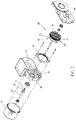
FIG. 2 is an exploded view showing the present invention. -
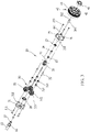
FIG. 3 is an exploded view showing a coaxial gear set according to the present invention. -
FIG. 4 is a cross-sectional view showing the present invention in an assembled form. -
FIG. 5 is a cross-sectional view of the present invention taken along line 5-5 ofFIG. 4 . -
FIG. 6 is a cross-sectional view of the present invention taken along line 6-6 ofFIG. 4 . - A structure of the present invention, as shown in
FIGS. 1 and2 , is made up of ahousing 10, atransmission axle 15 arranged at a center of thehousing 10, an internally-toothed ring track 18 arranged on an inner circumference of thehousing 10, and a coaxial gear set 20 arranged between thetransmission axle 15 and the internally-toothed ring track 18. - For a detailed structure of a preferred embodiment according to the present invention, reference being had to
FIGS. 1 and2 , thehousing 10 includes afirst mounting compartment 11 and asecond mounting compartment 12. Thetransmission axle 15 is rotatably arranged in thefirst mounting compartment 11 for mounting thecoaxial gear set 20 that is arranged on thetransmission axle 15. Thesecond mounting compartment 12 is provided for disposition of a driven member (not shown in the drawings) in meshing engagement with thecoaxial gear set 20. Thehousing 10 is provided, respectively at of a front end and a rear end thereof, with afirst cover 13 and asecond cover 14 fastened thereto and covering thereon for protection of internal components thereof. Two ends of thetransmission axle 15 are rotatably mounted, as being each supported by a bearing, to thehousing 10 and thefirst cover 13. The end of thetransmission axle 15 that extends through thehousing 10 is formed with amounting section 16 and acoupling section 17 for receiving the coaxial gear set 20 to mount thereon and to realize an operative coupling relationship therebetween. The internally-toothed ring track 18 is fixed to the inner circumference of thefirst mounting compartment 11 of thehousing 10 to receive the coaxial gear set 20 to mesh therewith. - For a detailed structure of the
coaxial gear set 20, reference being had toFIGS. 2 ,3 , and4 , thecoaxial gear set 20 comprises a modularized structure formed of asun gear 21, aplanetary gear set 30, and aoutput member 40, wherein thesun gear 21 and thetransmission axle 15 are arranged as an integrated unity structure or a combined structure, and in the present invention, thesun gear 21 and thetransmission axle 15 being arranged to form a combined structure is taken as a primary example. Thesun gear 21 is formed, in a center thereof, with acoupling hole 22 that is fit over themounting section 16 of thetransmission axle 15. Acoupling block 23 is inserted into and disposed in thecoupling hole 22 to engage with thecoupling section 17 of thetransmission axle 15. A fasteningmember 24 penetrates through and presses on thecoupling block 23 and is then fastened to the transmission axle 15 (as shown inFIG. 4 ), so that thecoaxial gear set 20 is selectively mounted to themounting section 16 of thetransmission axle 15 by means of thesun gear 21, and theplanetary gear set 30 is rotatably mounted on thesun gear 21 by means of a first bearing 25 and a second bearing 27 that are arranged at two ends of thesun gear 21. According to some embodiments, the first andsecond bearings planetary gear set 30 may alternatively arranged at two ends of thetransmission axle 15 that correspond to thesun gear 21. Further, at the two ends of thesun gear 21, afirst carrier frame 31 and asecond carrier frame 35, and also a plurality of steppedplanetary gears 33 that mesh with and surround thesun gear 21 are arranged, wherein thefirst carrier frame 31 is mounted by the first bearing 25 to one of the ends of thesun gear 21, and thesecond carrier frame 35 is provided, at a center thereof, with anaxle tube 36 for mounting theoutput member 40, and a free end of theaxle tube 36 is rotatably mounted, by means of a bearing, to the second cover 14 (as shown inFIG. 4 ). Theaxle tube 36 of thesecond carrier frame 35 is provided, at a center thereof, with a steppedmounting hole 360 that receives a mountingaxle 361 to penetrate therein and press thereon, such that an end of themounting axle 361 is mounted, by means of the second bearing 27, to an opposite one of the ends of thesun gear 21. Themounting axle 361 is formed with athrough hole 362, which receives a hand tool to insert therein for operating the fasteningmember 24 of thecoupling block 23 of thesun gear 21. Surfaces of the first andsecond carrier frames hole pillars fastening elements second carrier frames sun gear 21 to attach to each other as a unity. A plurality ofaxle bars 32 are arranged between the first andsecond carrier frames planetary gears 33. Each of theaxle bars 32 rotatably supports a corresponding one of the steppedplanetary gears 33 by means of at least one bearing 321. Each of the steppedplanetary gears 33 includes a first toothed portion 331 (as shown inFIG. 5 ) that simultaneously mesh with both thesun gear 21 and the internally-toothed ring track 18, and each of the steppedplanetary gears 33 is provided with a second toothed portion 332 (as shown inFIG. 6 ) located at one side and integrated with thefirst toothed portion 331 to mesh with theoutput member 40, so that thesun gear 21 of thecoaxial gear set 20 may simultaneously drive the firsttoothed portions 331 of the steppedplanetary gears 33 to cause each of the steppedplanetary gears 33 to generate spinning in a reversed direction (relative to a rotation direction of thesun gear 21, this being applicable hereinafter), and at the same time, being constrained by the internally-toothed ring track 18, the steppedplanetary gears 33 are caused to simultaneously generate orbiting relative to thesun gear 21 in the same direction (as shown inFIG. 5 ) for driving the planetary gear set 30. Further, the secondtoothed portions 332 of the steppedplanetary gears 33 synchronously drive theoutput member 40 to generate an output of rotation in a reversed direction (as shown inFIG. 6 ), and due to the rotation of the planetary gear set 30 as the above-described orbiting in the same direction, a phenomenon of backward rotating is induced to thereby enhance an effect of reduction. Theoutput member 40 is rotatably mounted, by means of a third bearing 41, to theaxle tube 36 of thesecond carrier frame 35 of theplanetary gear set 30. Theoutput member 40 is formed, on an inner circumference thereof, with aninternal toothed circumference 42 that is engageable with the secondtoothed portions 332 of the steppedplanetary gears 33 of theplanetary gear set 30, and theoutput member 40 is formed, on an outer circumference thereof, with adriving wheel portion 45 that is engageable with the driven member (not shown in the drawings). Thedriving wheel portion 45 can be an externally toothed wheel or a frictional wheel, and in the present invention, an externally toothed wheel is taken as an example of thedriving wheel portion 45 of theoutput member 40. - As such, the first
toothed portions 331 of the steppedplanetary gears 33 of theplanetary gear set 30 are set in synchronous meshing engagement with the internally-toothed ring track 18, while the secondtoothed portions 332 that are integrally formed therewith are in direct meshing engagement with theinternal toothed circumference 42 of theoutput member 40, so as to form a short-axle-distance large-speed-ratio gear set structure. - An actual operation of the present invention will be described. As shown in
FIGS. 3 ,4 , and5 , since thecoaxial gear set 20 is arranged such that the planetary gear set 30 and theoutput member 40 are mounted on thesun gear 21, so that thecoaxial gear set 20 can be formed as a modularized structure for directly mounting on thetransmission axle 15, such that the firsttoothed portions 331 of the steppedplanetary gears 33 of the planetary gear set 30 of thecoaxial gear set 20 are in meshing engagement with the internally-toothed ring track 18 of thehousing 10, and, with the fasteningmember 24 of thecoupling block 23 of thesun gear 21 being fastened to thetransmission axle 15, thetransmission axle 15, when being driven, may synchronously drive thesun gear 21 of the coaxial gear set 20 to rotate in synchronization therewith, allowing thesun gear 21 to synchronously drive the planetary gear set 30 by means of the firsttoothed portions 331 of the steppedplanetary gears 33 to cause each of the steppedplanetary gears 33 of the planetary gear set 30 to generate spinning in a reversed direction (relative to the rotation direction of thesun gear 21, this being equally applied below), and due to being constrained by the internally-toothed ring track 18 that is fixed in position, the first andsecond carrier frames planetary gear set 30 are caused to drive each of the steppedplanetary gears 33 to generate orbiting about thesun gear 21 synchronously and in the same direction (as shown inFIG. 5 ). Thesecond toothed portion 332 of each of the steppedplanetary gears 33, being in meshing engagement with theinternal toothed circumference 42 of theoutput member 40, may synchronously drive theoutput member 40 to generate reversed-direction rotation (as shown inFIG. 6 ). Due to the rotation of the planetary gear set 30 as orbiting synchronously and in the same direction, theplanetary gear set 30 is caused to generate a phenomenon of backward rotation, and this could enhance the effect of speed reduction. And, theoutput member 40, due to being coupled, by means of thedriving wheel portion 45 of the outer circumference thereof, with the driven member, may drive the driven member (not shown in the drawings). - Based on the design and description provided above, the present invention provides that the
coaxial gear set 20 is mounted on thetransmission axle 15 of thehousing 10, and the firsttoothed portion 331 of each of the steppedplanetary gears 33 of theplanetary gear set 30 are synchronously in meshing engagement with both thesun gear 21 and the internally-toothed ring track 18, and the secondtoothed portion 332 of each of the steppedplanetary gears 33 is individually set in meshing engagement with theinternal toothed circumference 42 of theoutput member 40, so as to achieve dual inputs and single output, and thus forming a short-axle-distance structure, allowing for size reduction. Further, the planetary gear set 30, when driving theoutput member 40, can rotate backward in a reversed direction to achieve a large speed ratio to further enhance the effect of speed reduction, and also to reduce interference, allowing the entire operation to be smoother and also helping reduce vibration and noise, thereby making the entire assembly structure of the reduction mechanism more secured and enhancing degree of meshing engagement to extend the service life thereof.
Claims (9)
- A short-axle-distance large-speed-ratio gear set structure, comprising:a housing (10);a transmission axle (15), which is rotatably mounted in the housing (10), the transmission axle (15) being provided with a sun gear (21);an internally-toothed ring track (18), which is fixed to the housing (10);a planetary gear set (30), which comprises a first carrier frame (31) and a second carrier frame (35) that are opposite to each other, a plurality of stepped planetary gears (33) being rotatably arranged between the first and second carrier frames (31, 35) and around an outer circumference of the sun gear (21), each of the stepped planetary gears (33) comprising a first toothed portion (331) synchronously meshing with the sun gear (21) and the internally-toothed ring track (18), each of the stepped planetary gears (33) further comprising a second toothed portion (332) that is rotatable in unison with the first toothed portion (331); andan output member (40), which has an inner circumference that is formed with an internal toothed circumference (42) engageable with the second toothed portion (332) of each of the stepped planetary gears (33), the output member (40) having an outer circumference that is formed with a driving wheel portion (45) for driving purposes.
- The short-axle-distance large-speed-ratio gear set structure according to claim 1, wherein the housing (10) comprises at least a first mounting compartment (11) for mounting the transmission axle (15), the housing (10) having a front end and a rear end that are respectively covered by a first cover (13) and a second cover (14) mounted thereto, two ends of the transmission axle (15) being rotatably mounted, as being each supported by a bearing, between the housing (10) and the first cover (13).
- The short-axle-distance large-speed-ratio gear set structure according to claim 1, wherein one end of the transmission axle (15) is formed with a mounting section (16) and a coupling section (17), and the sun gear (21) is formed, in a center thereof, with a coupling hole (22) that is fit over the mounting section (16), a coupling block (23) being inserted into and disposed in the coupling hole (22) to engage with the coupling section (17) of the transmission axle (15), a fastening member (24) penetrating through and pressing on the coupling block (23) to then fasten to the transmission axle (15).
- The short-axle-distance large-speed-ratio gear set structure according to claim 1, wherein the second carrier frame (35) of the planetary gear set (30) is provided, at a center thereof, with an axle tube (36) for mounting the output member (40), the axle tube (36) rotatably supporting the output member (40) by means of a third bearing (41).
- The short-axle-distance large-speed-ratio gear set structure according to claim 4, wherein the axle tube (36) of the second carrier frame (35) is provided, at a center thereof, with a stepped mounting hole (360) that receives a mounting axle (361) to penetrate therein, one end of the mounting axle (361) being rotatably mounted on an opposite end of the sun gear (21), wherein the mounting axle (361) is formed with a through hole (362) for receiving a hand tool to insert and operate therein.
- The short-axle-distance large-speed-ratio gear set structure according to claim 1, wherein surfaces of the first and second carrier frames (31, 35) of the planetary gear set (30) that face each other are respectively provided with a plurality of counterbored-hole pillars (310, 350), which are set in abutting engagement with each other and respectively receive threaded fastening elements (311, 351) to penetrate therethrough for mutually fastening to each other, so as to have the first and second carrier frames (31, 35) to attach to each other as a unity.
- The short-axle-distance large-speed-ratio gear set structure according to claim 1, wherein a plurality of axle bars (32) are arranged between the first and second carrier frames (31, 35) for mounting the stepped planetary gears (33), and each of the axle bars (32) rotatably supports a corresponding one of the stepped planetary gears (33) by means of at least one bearing (321).
- The short-axle-distance large-speed-ratio gear set structure according to claim 1, wherein the driving wheel portion (45) on the outer circumference of the output member (40) includes an externally toothed wheel or a frictional wheel.
- The short-axle-distance large-speed-ratio gear set structure according to any one of claims 1-8, wherein the first and second carrier frames (31, 35) of the planetary gear set (30) are rotatably mounted, by means of a first bearing (25) and a second bearing (27) arranged at centers thereof, to two ends of the sun gear (21), such that the sun gear (21), the planetary gear set (30), and the output member (40) are assembled together as a modularized coaxial gear set (20).
Applications Claiming Priority (1)
| Application Number | Priority Date | Filing Date | Title |
|---|---|---|---|
| TW109145760A TWI764462B (en) | 2020-12-23 | 2020-12-23 | Short-wheelbase and high-speed ratio gear set structure |
Publications (3)
| Publication Number | Publication Date |
|---|---|
| EP4019804A1 true EP4019804A1 (en) | 2022-06-29 |
| EP4019804C0 EP4019804C0 (en) | 2025-07-23 |
| EP4019804B1 EP4019804B1 (en) | 2025-07-23 |
Family
ID=79021584
Family Applications (1)
| Application Number | Title | Priority Date | Filing Date |
|---|---|---|---|
| EP21216185.5A Active EP4019804B1 (en) | 2020-12-23 | 2021-12-21 | Short-axle large-speed-ratio gear set structure |
Country Status (5)
| Country | Link |
|---|---|
| US (1) | US11578785B2 (en) |
| EP (1) | EP4019804B1 (en) |
| JP (2) | JP3236956U (en) |
| CN (2) | CN114658809B (en) |
| TW (1) | TWI764462B (en) |
Families Citing this family (1)
| Publication number | Priority date | Publication date | Assignee | Title |
|---|---|---|---|---|
| TWI764462B (en) * | 2020-12-23 | 2022-05-11 | 姚立和 | Short-wheelbase and high-speed ratio gear set structure |
Citations (3)
| Publication number | Priority date | Publication date | Assignee | Title |
|---|---|---|---|---|
| US2891767A (en) * | 1954-12-17 | 1959-06-23 | Euclid Crane & Hoist Company | Hoist with gear reduction |
| WO2013043822A2 (en) * | 2011-09-22 | 2013-03-28 | The Timken Company | Compact planetary gear system with stiffened carrier |
| DE102019114801A1 (en) * | 2019-06-03 | 2020-12-03 | Schaeffler Technologies AG & Co. KG | Electric final drive with a planetary gear |
Family Cites Families (23)
| Publication number | Priority date | Publication date | Assignee | Title |
|---|---|---|---|---|
| US1417797A (en) * | 1918-06-14 | 1922-05-30 | Cook | Speed-changing gear |
| JPS5241766A (en) * | 1975-09-30 | 1977-03-31 | Teijin Seiki Co Ltd | Planetary gear type transmission |
| JPS5754752U (en) * | 1980-09-16 | 1982-03-30 | ||
| JPS5923144A (en) * | 1982-07-28 | 1984-02-06 | Fuji Tekkosho:Kk | Gear of planetary gear transmission |
| JP3796931B2 (en) * | 1997-11-21 | 2006-07-12 | マツダ株式会社 | Rotation phase controller |
| JP3825554B2 (en) * | 1998-02-25 | 2006-09-27 | ヤンマー株式会社 | Work vehicle |
| JP2002250408A (en) * | 2001-02-23 | 2002-09-06 | Asmo Co Ltd | Motor actuator |
| US7100722B2 (en) * | 2002-08-29 | 2006-09-05 | Peerless-Winsmith, Inc. | Wheel assembly including a DC motor mounted within the HUB and drive connected to the wheel |
| TWM348169U (en) * | 2008-07-24 | 2009-01-01 | Sheng-Bo Wang | Speed-reduction device |
| TWM454479U (en) * | 2010-05-10 | 2013-06-01 | Univ Nat Formosa | Planetary gear speed-reduction device |
| TWM426686U (en) * | 2011-09-20 | 2012-04-11 | Hwa Kai Entpr Co Ltd De | Planetary gearbox structure |
| JP2016080069A (en) | 2014-10-16 | 2016-05-16 | 株式会社ジェイテクト | Planetary gear set |
| DE102017120985A1 (en) * | 2016-09-14 | 2018-03-15 | Borgwarner Inc. | ELECTRIC VEHICLE DRIVE SYSTEM |
| TWM543309U (en) * | 2017-01-04 | 2017-06-11 | Anjet Machinery Co Ltd | Shell moving type vertical planetary gear reducer |
| US11174782B2 (en) * | 2017-02-10 | 2021-11-16 | Pratt & Whitney Canada Corp. | Planetary gearbox for gas turbine engine |
| JP2018173033A (en) * | 2017-03-31 | 2018-11-08 | 株式会社 神崎高級工機製作所 | Engine start power generation unit and hydraulic circuit |
| JP6442549B2 (en) * | 2017-04-11 | 2018-12-19 | 安捷機械有限公司 | Case-driven planetary gear reduction mechanism for vertical mixer |
| CN207843216U (en) * | 2017-12-29 | 2018-09-11 | 宁波麦思动力系统有限公司 | Transmission device, driving device and the electric vehicle with driving device |
| US10876596B1 (en) * | 2018-06-29 | 2020-12-29 | Hydro-Gear Limited Partnership | Electric motor with compound planetary gear drive |
| TWI671171B (en) * | 2018-10-18 | 2019-09-11 | 龍崴股份有限公司 | Electric and pneumatic tool transmission structure |
| CN210566056U (en) * | 2019-08-09 | 2020-05-19 | 赵必成 | Speed reducer |
| TWI764462B (en) * | 2020-12-23 | 2022-05-11 | 姚立和 | Short-wheelbase and high-speed ratio gear set structure |
| TWM612179U (en) * | 2020-12-23 | 2021-05-21 | 姚立和 | Short wheel base and high speed ratio gear group structure |
-
2020
- 2020-12-23 TW TW109145760A patent/TWI764462B/en active
-
2021
- 2021-12-20 CN CN202111564579.0A patent/CN114658809B/en active Active
- 2021-12-20 CN CN202123212668.7U patent/CN217271695U/en not_active Withdrawn - After Issue
- 2021-12-21 EP EP21216185.5A patent/EP4019804B1/en active Active
- 2021-12-22 US US17/558,607 patent/US11578785B2/en active Active
- 2021-12-22 JP JP2021004922U patent/JP3236956U/en active Active
- 2021-12-22 JP JP2021208699A patent/JP7316625B2/en active Active
Patent Citations (3)
| Publication number | Priority date | Publication date | Assignee | Title |
|---|---|---|---|---|
| US2891767A (en) * | 1954-12-17 | 1959-06-23 | Euclid Crane & Hoist Company | Hoist with gear reduction |
| WO2013043822A2 (en) * | 2011-09-22 | 2013-03-28 | The Timken Company | Compact planetary gear system with stiffened carrier |
| DE102019114801A1 (en) * | 2019-06-03 | 2020-12-03 | Schaeffler Technologies AG & Co. KG | Electric final drive with a planetary gear |
Also Published As
| Publication number | Publication date |
|---|---|
| EP4019804C0 (en) | 2025-07-23 |
| CN114658809A (en) | 2022-06-24 |
| EP4019804B1 (en) | 2025-07-23 |
| JP2022100298A (en) | 2022-07-05 |
| US20220196117A1 (en) | 2022-06-23 |
| JP3236956U (en) | 2022-04-01 |
| US11578785B2 (en) | 2023-02-14 |
| CN217271695U (en) | 2022-08-23 |
| JP7316625B2 (en) | 2023-07-28 |
| TWI764462B (en) | 2022-05-11 |
| TW202225582A (en) | 2022-07-01 |
| CN114658809B (en) | 2025-10-31 |
Similar Documents
| Publication | Publication Date | Title |
|---|---|---|
| KR20000071452A (en) | Driving apparatus | |
| JPH10266948A (en) | Tandem type pump with auxiliary pump | |
| EP4027030B1 (en) | Coupling structure and modularized coaxial gear train reduction mechanism using same | |
| JP2003278849A (en) | Reduction gear and reduction gear series | |
| US11578785B2 (en) | Short-axle-distance large-speed-ratio gear set structure | |
| US11686372B2 (en) | Modularized coaxial gear set reduction mechanism | |
| JP2866249B2 (en) | Speed reducer series with internal meshing planetary gear structure | |
| JP3100286B2 (en) | Geared motor series | |
| JP3034766B2 (en) | Geared motor series | |
| KR100579705B1 (en) | Planetary gear reducer | |
| CN213831995U (en) | Motor speed reduction output mechanism and middle motor | |
| CN213064584U (en) | Double-shaft synchronous output permanent magnet direct current motor | |
| JP2002323095A (en) | Planetary gear transmission | |
| JP2003287104A (en) | Torque converter | |
| CN107701667B (en) | Composite speed reducer | |
| JPH11207558A (en) | Machine tool headstock | |
| CN113996380B (en) | Built-in speed reduction crusher | |
| CN224229187U (en) | Two-stage planetary gear reducer | |
| TWM612179U (en) | Short wheel base and high speed ratio gear group structure | |
| CN218761166U (en) | Planetary gear speed reducing motor | |
| CN213899814U (en) | High-torque-output and high-integration hub power module | |
| CN222026221U (en) | Pure electric reduction device, drive assembly and vehicle thereof | |
| CN222487180U (en) | Food processor with speed change function | |
| CN220523189U (en) | Speed reducer | |
| CN220646642U (en) | Helical tooth planetary reducer |
Legal Events
| Date | Code | Title | Description |
|---|---|---|---|
| PUAI | Public reference made under article 153(3) epc to a published international application that has entered the european phase |
Free format text: ORIGINAL CODE: 0009012 |
|
| STAA | Information on the status of an ep patent application or granted ep patent |
Free format text: STATUS: THE APPLICATION HAS BEEN PUBLISHED |
|
| AK | Designated contracting states |
Kind code of ref document: A1 Designated state(s): AL AT BE BG CH CY CZ DE DK EE ES FI FR GB GR HR HU IE IS IT LI LT LU LV MC MK MT NL NO PL PT RO RS SE SI SK SM TR |
|
| STAA | Information on the status of an ep patent application or granted ep patent |
Free format text: STATUS: REQUEST FOR EXAMINATION WAS MADE |
|
| 17P | Request for examination filed |
Effective date: 20221227 |
|
| RBV | Designated contracting states (corrected) |
Designated state(s): AL AT BE BG CH CY CZ DE DK EE ES FI FR GB GR HR HU IE IS IT LI LT LU LV MC MK MT NL NO PL PT RO RS SE SI SK SM TR |
|
| STAA | Information on the status of an ep patent application or granted ep patent |
Free format text: STATUS: EXAMINATION IS IN PROGRESS |
|
| 17Q | First examination report despatched |
Effective date: 20231107 |
|
| GRAP | Despatch of communication of intention to grant a patent |
Free format text: ORIGINAL CODE: EPIDOSNIGR1 |
|
| STAA | Information on the status of an ep patent application or granted ep patent |
Free format text: STATUS: GRANT OF PATENT IS INTENDED |
|
| RIC1 | Information provided on ipc code assigned before grant |
Ipc: F16H 57/08 20060101ALN20250204BHEP Ipc: F16H 57/00 20120101ALN20250204BHEP Ipc: F16H 57/021 20120101ALN20250204BHEP Ipc: F16H 57/02 20120101ALN20250204BHEP Ipc: F16H 1/28 20060101AFI20250204BHEP |
|
| RAP3 | Party data changed (applicant data changed or rights of an application transferred) |
Owner name: YAO, LI-HO |
|
| RIN1 | Information on inventor provided before grant (corrected) |
Inventor name: HSIEH, PI-JEN Inventor name: TIEN, CHI-CHEN Inventor name: HSIEH, PEI-SHENG Inventor name: LIEN, NORMAN Inventor name: YAO, LI-HO |
|
| INTG | Intention to grant announced |
Effective date: 20250220 |
|
| GRAS | Grant fee paid |
Free format text: ORIGINAL CODE: EPIDOSNIGR3 |
|
| GRAA | (expected) grant |
Free format text: ORIGINAL CODE: 0009210 |
|
| STAA | Information on the status of an ep patent application or granted ep patent |
Free format text: STATUS: THE PATENT HAS BEEN GRANTED |
|
| REG | Reference to a national code |
Ref country code: DE Ref legal event code: R081 Ref document number: 602021034532 Country of ref document: DE Owner name: YAO, LI-HO, TW Free format text: FORMER OWNER: LI-HO, YAO, TAIPEI CITY, TW |
|
| AK | Designated contracting states |
Kind code of ref document: B1 Designated state(s): AL AT BE BG CH CY CZ DE DK EE ES FI FR GB GR HR HU IE IS IT LI LT LU LV MC MK MT NL NO PL PT RO RS SE SI SK SM TR |
|
| REG | Reference to a national code |
Ref country code: GB Ref legal event code: FG4D |
|
| REG | Reference to a national code |
Ref country code: CH Ref legal event code: EP |
|
| REG | Reference to a national code |
Ref country code: IE Ref legal event code: FG4D |
|
| REG | Reference to a national code |
Ref country code: DE Ref legal event code: R096 Ref document number: 602021034532 Country of ref document: DE |
|
| U01 | Request for unitary effect filed |
Effective date: 20250806 |
|
| U07 | Unitary effect registered |
Designated state(s): AT BE BG DE DK EE FI FR IT LT LU LV MT NL PT RO SE SI Effective date: 20250819 |
|
| PG25 | Lapsed in a contracting state [announced via postgrant information from national office to epo] |
Ref country code: IS Free format text: LAPSE BECAUSE OF FAILURE TO SUBMIT A TRANSLATION OF THE DESCRIPTION OR TO PAY THE FEE WITHIN THE PRESCRIBED TIME-LIMIT Effective date: 20251123 |
|
| PG25 | Lapsed in a contracting state [announced via postgrant information from national office to epo] |
Ref country code: NO Free format text: LAPSE BECAUSE OF FAILURE TO SUBMIT A TRANSLATION OF THE DESCRIPTION OR TO PAY THE FEE WITHIN THE PRESCRIBED TIME-LIMIT Effective date: 20251023 |
|
| PG25 | Lapsed in a contracting state [announced via postgrant information from national office to epo] |
Ref country code: HR Free format text: LAPSE BECAUSE OF FAILURE TO SUBMIT A TRANSLATION OF THE DESCRIPTION OR TO PAY THE FEE WITHIN THE PRESCRIBED TIME-LIMIT Effective date: 20250723 |
|
| PG25 | Lapsed in a contracting state [announced via postgrant information from national office to epo] |
Ref country code: GR Free format text: LAPSE BECAUSE OF FAILURE TO SUBMIT A TRANSLATION OF THE DESCRIPTION OR TO PAY THE FEE WITHIN THE PRESCRIBED TIME-LIMIT Effective date: 20251024 |
|
| PG25 | Lapsed in a contracting state [announced via postgrant information from national office to epo] |
Ref country code: PL Free format text: LAPSE BECAUSE OF FAILURE TO SUBMIT A TRANSLATION OF THE DESCRIPTION OR TO PAY THE FEE WITHIN THE PRESCRIBED TIME-LIMIT Effective date: 20250723 |
|
| PG25 | Lapsed in a contracting state [announced via postgrant information from national office to epo] |
Ref country code: RS Free format text: LAPSE BECAUSE OF FAILURE TO SUBMIT A TRANSLATION OF THE DESCRIPTION OR TO PAY THE FEE WITHIN THE PRESCRIBED TIME-LIMIT Effective date: 20251023 |
|
| PG25 | Lapsed in a contracting state [announced via postgrant information from national office to epo] |
Ref country code: ES Free format text: LAPSE BECAUSE OF FAILURE TO SUBMIT A TRANSLATION OF THE DESCRIPTION OR TO PAY THE FEE WITHIN THE PRESCRIBED TIME-LIMIT Effective date: 20250723 |
|
| PG25 | Lapsed in a contracting state [announced via postgrant information from national office to epo] |
Ref country code: SM Free format text: LAPSE BECAUSE OF FAILURE TO SUBMIT A TRANSLATION OF THE DESCRIPTION OR TO PAY THE FEE WITHIN THE PRESCRIBED TIME-LIMIT Effective date: 20250723 |
|
| PG25 | Lapsed in a contracting state [announced via postgrant information from national office to epo] |
Ref country code: CZ Free format text: LAPSE BECAUSE OF FAILURE TO SUBMIT A TRANSLATION OF THE DESCRIPTION OR TO PAY THE FEE WITHIN THE PRESCRIBED TIME-LIMIT Effective date: 20250723 |
|
| PG25 | Lapsed in a contracting state [announced via postgrant information from national office to epo] |
Ref country code: SK Free format text: LAPSE BECAUSE OF FAILURE TO SUBMIT A TRANSLATION OF THE DESCRIPTION OR TO PAY THE FEE WITHIN THE PRESCRIBED TIME-LIMIT Effective date: 20250723 |
|
| PLBE | No opposition filed within time limit |
Free format text: ORIGINAL CODE: 0009261 |
|
| STAA | Information on the status of an ep patent application or granted ep patent |
Free format text: STATUS: NO OPPOSITION FILED WITHIN TIME LIMIT |
|
| REG | Reference to a national code |
Ref country code: CH Ref legal event code: L10 Free format text: ST27 STATUS EVENT CODE: U-0-0-L10-L00 (AS PROVIDED BY THE NATIONAL OFFICE) Effective date: 20260604 |
|
| 26N | No opposition filed |
Effective date: 20260424 |
|
| PG25 | Lapsed in a contracting state [announced via postgrant information from national office to epo] |
Ref country code: MC Free format text: LAPSE BECAUSE OF FAILURE TO SUBMIT A TRANSLATION OF THE DESCRIPTION OR TO PAY THE FEE WITHIN THE PRESCRIBED TIME-LIMIT Effective date: 20250723 |
|
| PGFP | Annual fee paid to national office [announced via postgrant information from national office to epo] |
Ref country code: GB Payment date: 20260618 Year of fee payment: 5 |
|
| REG | Reference to a national code |
Ref country code: CH Ref legal event code: H13 Free format text: ST27 STATUS EVENT CODE: U-0-0-H10-H13 (AS PROVIDED BY THE NATIONAL OFFICE) Effective date: 20260723 |
|
| U21 | Renewal fee for the european patent with unitary effect paid with additional fee |
Year of fee payment: 5 Effective date: 20260622 |