EP4019775A1 - Gear pump with gear including etched surfaces - Google Patents
Gear pump with gear including etched surfaces Download PDFInfo
- Publication number
- EP4019775A1 EP4019775A1 EP21206565.0A EP21206565A EP4019775A1 EP 4019775 A1 EP4019775 A1 EP 4019775A1 EP 21206565 A EP21206565 A EP 21206565A EP 4019775 A1 EP4019775 A1 EP 4019775A1
- Authority
- EP
- European Patent Office
- Prior art keywords
- gear
- radially outwardly
- facing surface
- outwardly facing
- chamfered portion
- Prior art date
- Legal status (The legal status is an assumption and is not a legal conclusion. Google has not performed a legal analysis and makes no representation as to the accuracy of the status listed.)
- Pending
Links
- 239000000446 fuel Substances 0.000 claims description 17
- 239000012530 fluid Substances 0.000 description 13
- 239000000463 material Substances 0.000 description 12
- 229910000906 Bronze Inorganic materials 0.000 description 8
- 239000010974 bronze Substances 0.000 description 8
- KUNSUQLRTQLHQQ-UHFFFAOYSA-N copper tin Chemical compound [Cu].[Sn] KUNSUQLRTQLHQQ-UHFFFAOYSA-N 0.000 description 8
- 238000005461 lubrication Methods 0.000 description 4
- 239000000314 lubricant Substances 0.000 description 3
- XAGFODPZIPBFFR-UHFFFAOYSA-N aluminium Chemical compound [Al] XAGFODPZIPBFFR-UHFFFAOYSA-N 0.000 description 2
- 229910052782 aluminium Inorganic materials 0.000 description 2
- 230000020169 heat generation Effects 0.000 description 2
- 230000001050 lubricating effect Effects 0.000 description 2
- 238000000034 method Methods 0.000 description 2
- 230000009467 reduction Effects 0.000 description 2
- 238000012546 transfer Methods 0.000 description 2
- 238000003466 welding Methods 0.000 description 2
- 229910000831 Steel Inorganic materials 0.000 description 1
- 230000008901 benefit Effects 0.000 description 1
- 239000002826 coolant Substances 0.000 description 1
- 230000003247 decreasing effect Effects 0.000 description 1
- 230000003993 interaction Effects 0.000 description 1
- 238000010329 laser etching Methods 0.000 description 1
- 238000012423 maintenance Methods 0.000 description 1
- 238000005259 measurement Methods 0.000 description 1
- 238000012986 modification Methods 0.000 description 1
- 230000004048 modification Effects 0.000 description 1
- 230000008569 process Effects 0.000 description 1
- 230000002035 prolonged effect Effects 0.000 description 1
- 239000010959 steel Substances 0.000 description 1
Images


Classifications
-
- F—MECHANICAL ENGINEERING; LIGHTING; HEATING; WEAPONS; BLASTING
- F04—POSITIVE - DISPLACEMENT MACHINES FOR LIQUIDS; PUMPS FOR LIQUIDS OR ELASTIC FLUIDS
- F04C—ROTARY-PISTON, OR OSCILLATING-PISTON, POSITIVE-DISPLACEMENT MACHINES FOR LIQUIDS; ROTARY-PISTON, OR OSCILLATING-PISTON, POSITIVE-DISPLACEMENT PUMPS
- F04C2/00—Rotary-piston machines or pumps
- F04C2/08—Rotary-piston machines or pumps of intermeshing-engagement type, i.e. with engagement of co-operating members similar to that of toothed gearing
- F04C2/082—Details specially related to intermeshing engagement type machines or pumps
- F04C2/084—Toothed wheels
-
- F—MECHANICAL ENGINEERING; LIGHTING; HEATING; WEAPONS; BLASTING
- F04—POSITIVE - DISPLACEMENT MACHINES FOR LIQUIDS; PUMPS FOR LIQUIDS OR ELASTIC FLUIDS
- F04C—ROTARY-PISTON, OR OSCILLATING-PISTON, POSITIVE-DISPLACEMENT MACHINES FOR LIQUIDS; ROTARY-PISTON, OR OSCILLATING-PISTON, POSITIVE-DISPLACEMENT PUMPS
- F04C2/00—Rotary-piston machines or pumps
- F04C2/08—Rotary-piston machines or pumps of intermeshing-engagement type, i.e. with engagement of co-operating members similar to that of toothed gearing
- F04C2/12—Rotary-piston machines or pumps of intermeshing-engagement type, i.e. with engagement of co-operating members similar to that of toothed gearing of other than internal-axis type
- F04C2/14—Rotary-piston machines or pumps of intermeshing-engagement type, i.e. with engagement of co-operating members similar to that of toothed gearing of other than internal-axis type with toothed rotary pistons
- F04C2/18—Rotary-piston machines or pumps of intermeshing-engagement type, i.e. with engagement of co-operating members similar to that of toothed gearing of other than internal-axis type with toothed rotary pistons with similar tooth forms
-
- F—MECHANICAL ENGINEERING; LIGHTING; HEATING; WEAPONS; BLASTING
- F04—POSITIVE - DISPLACEMENT MACHINES FOR LIQUIDS; PUMPS FOR LIQUIDS OR ELASTIC FLUIDS
- F04C—ROTARY-PISTON, OR OSCILLATING-PISTON, POSITIVE-DISPLACEMENT MACHINES FOR LIQUIDS; ROTARY-PISTON, OR OSCILLATING-PISTON, POSITIVE-DISPLACEMENT PUMPS
- F04C2210/00—Fluid
- F04C2210/10—Fluid working
- F04C2210/1044—Fuel
-
- F—MECHANICAL ENGINEERING; LIGHTING; HEATING; WEAPONS; BLASTING
- F04—POSITIVE - DISPLACEMENT MACHINES FOR LIQUIDS; PUMPS FOR LIQUIDS OR ELASTIC FLUIDS
- F04C—ROTARY-PISTON, OR OSCILLATING-PISTON, POSITIVE-DISPLACEMENT MACHINES FOR LIQUIDS; ROTARY-PISTON, OR OSCILLATING-PISTON, POSITIVE-DISPLACEMENT PUMPS
- F04C2210/00—Fluid
- F04C2210/20—Fluid liquid, i.e. incompressible
- F04C2210/203—Fuel
-
- F—MECHANICAL ENGINEERING; LIGHTING; HEATING; WEAPONS; BLASTING
- F04—POSITIVE - DISPLACEMENT MACHINES FOR LIQUIDS; PUMPS FOR LIQUIDS OR ELASTIC FLUIDS
- F04C—ROTARY-PISTON, OR OSCILLATING-PISTON, POSITIVE-DISPLACEMENT MACHINES FOR LIQUIDS; ROTARY-PISTON, OR OSCILLATING-PISTON, POSITIVE-DISPLACEMENT PUMPS
- F04C2240/00—Components
- F04C2240/30—Casings or housings
-
- F—MECHANICAL ENGINEERING; LIGHTING; HEATING; WEAPONS; BLASTING
- F04—POSITIVE - DISPLACEMENT MACHINES FOR LIQUIDS; PUMPS FOR LIQUIDS OR ELASTIC FLUIDS
- F04C—ROTARY-PISTON, OR OSCILLATING-PISTON, POSITIVE-DISPLACEMENT MACHINES FOR LIQUIDS; ROTARY-PISTON, OR OSCILLATING-PISTON, POSITIVE-DISPLACEMENT PUMPS
- F04C2240/00—Components
- F04C2240/50—Bearings
-
- F—MECHANICAL ENGINEERING; LIGHTING; HEATING; WEAPONS; BLASTING
- F04—POSITIVE - DISPLACEMENT MACHINES FOR LIQUIDS; PUMPS FOR LIQUIDS OR ELASTIC FLUIDS
- F04C—ROTARY-PISTON, OR OSCILLATING-PISTON, POSITIVE-DISPLACEMENT MACHINES FOR LIQUIDS; ROTARY-PISTON, OR OSCILLATING-PISTON, POSITIVE-DISPLACEMENT PUMPS
- F04C2250/00—Geometry
Definitions
- Exemplary embodiments pertain to the art of gear pumps, more specifically to a gear pump having etched gear surfaces.
- gears are supported by bearings that promote rotation. As the gears rotate, gear teeth mesh. The meshing of the gear teeth leads to an inter-tooth decreasing volume causing flow and downstream restrictions that generate pressure in a fluid.
- the fluid is passed through a conduit and, in the case of fuel, often times to an engine.
- the bearings are often formed from leaded bronze. Leaded bronze can withstand prolonged exposure to fuel and possesses a conformability and thermal conductivity that resists galling and friction welding.
- a gear for a pump including a gear body defining a root circle, and a plurality of gear teeth extending from the gear body radially outwardly of the root circle.
- Each of the plurality of gear teeth have a tip portion, a leading edge, a trailing edge, a circular thickness defined between the leading edge and the trailing edge, a first radially outwardly facing surface and a second radially outwardly facing surface.
- At least one of the first radially outwardly facing surface and the second radially outwardly facing surface includes a chamfered portion that extends from the leading edge toward the trailing edge across a portion of the circular thickness.
- a fuel pump including a housing having an interior, an inlet, and an outlet.
- a stationary bearing is mounted in the interior.
- a pressure loaded bearing is positioned in the interior opposite the stationary bearing.
- a gear is rotatably supported between the pressure loaded bearing and the stationary bearing.
- the gear includes a gear body having a root circle, and a plurality of gear teeth extending from the gear body radially outwardly of the root circle.
- Each of the plurality of gear teeth have a tip portion, a leading edge, a trailing edge, a circular thickness defined between the leading edge and the trailing edge, a first radially outwardly facing surface and a second radially outwardly facing surface.
- At least one of the first radially outwardly facing surface and the second radially outwardly facing surface includes a chamfered portion that extends from the leading edge toward the trailing edge across a portion of the circular thickness.
- Fuel pump 10 includes a housing 14 having an interior 18. Housing 14 includes an inlet 20 that leads fluid, such as fuel, into interior 18 and an outlet 22 that may direct the fluid from housing 14.
- a gear system 24 is disposed in interior 18. Gear system 24 is selectively activated in order to create a force that motivates the fluid from inlet 20 through outlet 22.
- gear system 24 includes a drive pressure loaded bearing or bushing 28 mounted in housing 14.
- a drive stationary bearing or bushing 30 is arranged axially opposite drive pressure loaded bearing 28.
- a drive gear 32 is mounted to a drive shaft 34 that is rotatably supported between drive pressure loaded bearing 28 and drive stationary bearing 30. That is, drive pressure loaded bearing 28 includes an opening 38 that receives a first end (not separately labeled) of drive shaft 34 and drive stationary bearing 30 includes an opening 40 that receives a second end (also not separately labeled) of drive shaft 34.
- Drive shaft 34 is connected to a motive source, such as a motor (not shown), and driven to rotate drive gear 32.
- drive pressure loaded bearing 28 and drive stationary bearing 30 are formed from a material such as leaded bronze. However, it should be understood that other materials, such as aluminum, other bronze variants, or other materials that are compatible with the fluid and PV's may also be used.
- Gear system 24 also includes a driven pressure loaded bearing or bushing 46 mounted in housing 14.
- a driven stationary bearing or bushing 48 is arranged axially opposite driven pressure loaded bearing 46.
- a driven gear 50 is mounted to a driven shaft 54 that is rotatably supported between driven pressure loaded bearing 46 and driven stationary bearing 48. That is, driven pressure loaded bearing 46 includes an opening portion 58 that receives a first end portion (not separately labeled) of driven shaft 54 and driven stationary bearing 48 includes an opening portion 60 that receives a second end portion (also not separately labeled) of driven shaft 54. Driven shaft 54 is rotated through an interaction between drive gear 32 and driven gear 50.
- driven pressure loaded bearing 46 and driven stationary bearing 48 are formed from a material such as leaded bronze. However, it should be understood that other materials, such as aluminum, other bronze variants, or other materials that are compatible with the fluid and PV's may also be used.
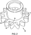
- drive gear 32 includes a gear body 71 that may be press-fit onto drive shaft 34 or machined from a common barstock. Of course, drive gear 32 could also be mounted to drive shaft 34 through a key or through a brazed connection.
- Gear body 71 includes a root circle 78 from which radially outwardly project a plurality of gear teeth, one of which is indicated at 84.
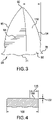
- each gear tooth 84 includes a base portion 90 positioned at root circle 78, a tip portion 92, a leading edge 94, and a trailing edge 96.
- Each gear tooth 84 also includes a first radially outwardly facing surface 99 and a second, opposing, radially outwardly facing surface 104.
- a circular thickness 108 is defined between leading edge 94 and trailing edge 96.
- the gears are a steel, but could be made from any number of other materials.
- gear tooth 84 includes a chamfered portion 116 that extends from leading edge 94 toward trailing edge 96 across a portion of circular thickness 108.
- chamfered portion 116 extends across about 43% of the circular thickness 108 so as to define a roll off width 120.
- chamfered portion 116 extends across about 40% of circular thickness 108.
- chamfered portion 116can range from about 15% to about 50% of the tooth circular thickness containing a chamfered portion.
- Chamfered portion 116 includes a height of between about 2 and about 4 light bands (between about 0.00058 mm and about 0.000116 mm). At this point, it should be understood that while shown on first radially outwardly facing surface 99 second radially outwardly facing surface 104 may also include a chamfered portion.
- Chamfered portion 116 may include a surface flatness of about 2.54 microns. The particular size and shape of the chamfered portion may vary and may be tailored to a particular tooth shape. Chamfered portion 116 forms an edge break that enhances and retains a surface film of lubricant (fuel) that increases service life of the pump, allows for increased pressures and speeds as well as the use of non-traditional bearing and gear material couples. It should be appreciated that the chamfered portion improves fluid entrainment results in an increase in fluid film. The increase in fluid film can results in a film region that exceeds a boundary layer or mixed film layer into full hydrodynamic lubrication which improves the load carrying capability of the gear and bearing material couple, improves heat transfer, and reduces friction and heat generation. Chamfered portion 116 may be formed through various laser etching processes that ensure high repeatability and maintenance of tolerances.
- Gear 130 may take the form of a drive gear or a driven gear.
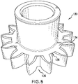
- gear 130 includes a gear body 134 having a root circle 136.
- each gear tooth 138 includes a base portion 144 at root circle 136 and a tip portion 146.
- Each gear tooth 138 also includes a leading edge 148 and a trailing edge 150 between which is defined a circular thickness 154.
- gear tooth 138 includes a first chamfered portion 158 that extends from leading edge 148 toward trailing edge 150 across about 15% of circular thickness 154.
- Gear tooth 138 also includes a second chamfered portion 160 that extends from trailing edge 150 toward leading edge 148 across about 15% of circular thickness 154.
- Each chamfered portion 158 and 160 includes a height of between about 2 and about 4 light bands (between about 0.00058 mm and about 0.000116 mm) and a surface flatness of about 1 micron.
- first radially outwardly facing surface 99 second radially outwardly facing surface 104 may also include a chamfered portion.
- Each chamfered portion 158, 160 forms an edge break, which depending upon a direction of rotation, enhances and retains a surface film of lubricant (fuel) that increases service life of the pump, allows for increased pressures and speeds as well as the use of non-traditional bearing and gear material couples.
- Chamfered portions 158 and 160 improve fluid entrainment that results in an increase in fluid film generated. The increase in the fluid film can bring the film region out of a boundary layer or mixed film layer into full hydrodynamic lubrication which improves the load carrying capability of the gear and bearing material couple, improves heat transfer, and reduces friction and heat generation.
Landscapes
- Engineering & Computer Science (AREA)
- Mechanical Engineering (AREA)
- General Engineering & Computer Science (AREA)
- Rotary Pumps (AREA)
- Details And Applications Of Rotary Liquid Pumps (AREA)
Abstract
Description
- Exemplary embodiments pertain to the art of gear pumps, more specifically to a gear pump having etched gear surfaces.
- Many pumps, including those used to provide a motive force to fuel, employ rotating gears. These gears are supported by bearings that promote rotation. As the gears rotate, gear teeth mesh. The meshing of the gear teeth leads to an inter-tooth decreasing volume causing flow and downstream restrictions that generate pressure in a fluid. The fluid is passed through a conduit and, in the case of fuel, often times to an engine. In fuel applications, the bearings are often formed from leaded bronze. Leaded bronze can withstand prolonged exposure to fuel and possesses a conformability and thermal conductivity that resists galling and friction welding.
- Surface properties of leaded bronze bearings have a limited PV value which is determined by multiplying a specific bearing load, or pressure (p), by sliding speed (v). The fuel, in addition to being passed through the pump, acts primarily as a coolant and a lubricant for pump components. As fuel gets hot, its viscosity drops; as fuel get cold, its viscosity increases. There is a general decrease in viscosity at higher temperatures, which results in a reduction in lubricating film thickness. The reduction in lubricating film thickness can lead to increased wear. Also, vapor filled cavities on gear tooth surfaces reduce surface contact with pump components which in turn lowers the lubrication benefit of fuel. Thus, fuel pumps that employ leaded bronze bearings have operational pressure, temperature, and speed limits. Accordingly, industry would more than welcome a fuel pump having components that resist galling and friction welding, while also being able to operate at higher temperatures and pressure ranges without loss of lubrication.
- Disclosed is a gear for a pump including a gear body defining a root circle, and a plurality of gear teeth extending from the gear body radially outwardly of the root circle. Each of the plurality of gear teeth have a tip portion, a leading edge, a trailing edge, a circular thickness defined between the leading edge and the trailing edge, a first radially outwardly facing surface and a second radially outwardly facing surface. At least one of the first radially outwardly facing surface and the second radially outwardly facing surface includes a chamfered portion that extends from the leading edge toward the trailing edge across a portion of the circular thickness.
- Also disclosed is a fuel pump including a housing having an interior, an inlet, and an outlet. A stationary bearing is mounted in the interior. A pressure loaded bearing is positioned in the interior opposite the stationary bearing. A gear is rotatably supported between the pressure loaded bearing and the stationary bearing. The gear includes a gear body having a root circle, and a plurality of gear teeth extending from the gear body radially outwardly of the root circle. Each of the plurality of gear teeth have a tip portion, a leading edge, a trailing edge, a circular thickness defined between the leading edge and the trailing edge, a first radially outwardly facing surface and a second radially outwardly facing surface. At least one of the first radially outwardly facing surface and the second radially outwardly facing surface includes a chamfered portion that extends from the leading edge toward the trailing edge across a portion of the circular thickness.
- The following descriptions should not be considered limiting in any way. With reference to the accompanying drawings, like elements are numbered alike:
-
FIG. 1 depicts a gear pump including gear teeth having a chamfered portion, in accordance with an exemplary embodiment; -
FIG. 2 depicts a perspective view of a gear from the gear pump ofFIG. 1 , in accordance with an exemplary aspect; -
FIG. 3 depicts a plane view showing a chamfered portion of a gear tooth of the gear fromFIG. 2 ; -
FIG. 4 is a partial end view of the gear tooth ofFIG. 3 showing a roll off width and a height of the chamfered portion; -
FIG. 5 depicts a perspective view of a gear from the gear pump, in accordance with another exemplary aspect; and -
FIG. 6 depicts a plane view showing chamfered portions of a gear tooth of the gear fromFIG. 5 . - A detailed description of one or more embodiments of the disclosed apparatus and method are presented herein by way of exemplification and not limitation with reference to the Figures.
- A fuel pump, in accordance with an exemplary aspect, is indicated generally at 10 in
FIG. 1 .Fuel pump 10 includes ahousing 14 having aninterior 18.Housing 14 includes aninlet 20 that leads fluid, such as fuel, intointerior 18 and anoutlet 22 that may direct the fluid fromhousing 14. Agear system 24 is disposed ininterior 18.Gear system 24 is selectively activated in order to create a force that motivates the fluid frominlet 20 throughoutlet 22. - In an embodiment,
gear system 24 includes a drive pressure loaded bearing or bushing 28 mounted inhousing 14. A drive stationary bearing or bushing 30 is arranged axially opposite drive pressure loadedbearing 28. Adrive gear 32 is mounted to adrive shaft 34 that is rotatably supported between drive pressure loaded bearing 28 and drivestationary bearing 30. That is, drive pressure loadedbearing 28 includes anopening 38 that receives a first end (not separately labeled) ofdrive shaft 34 and drivestationary bearing 30 includes an opening 40 that receives a second end (also not separately labeled) ofdrive shaft 34.Drive shaft 34 is connected to a motive source, such as a motor (not shown), and driven to rotatedrive gear 32. In an embodiment, drive pressure loaded bearing 28 and drivestationary bearing 30 are formed from a material such as leaded bronze. However, it should be understood that other materials, such as aluminum, other bronze variants, or other materials that are compatible with the fluid and PV's may also be used. -
Gear system 24 also includes a driven pressure loaded bearing or bushing 46 mounted inhousing 14. A driven stationary bearing or bushing 48 is arranged axially opposite driven pressure loaded bearing 46. A drivengear 50 is mounted to a drivenshaft 54 that is rotatably supported between driven pressure loaded bearing 46 and drivenstationary bearing 48. That is, driven pressure loaded bearing 46 includes anopening portion 58 that receives a first end portion (not separately labeled) of drivenshaft 54 and drivenstationary bearing 48 includes anopening portion 60 that receives a second end portion (also not separately labeled) of drivenshaft 54.Driven shaft 54 is rotated through an interaction betweendrive gear 32 and drivengear 50. In an embodiment, driven pressure loaded bearing 46 and drivenstationary bearing 48 are formed from a material such as leaded bronze. However, it should be understood that other materials, such as aluminum, other bronze variants, or other materials that are compatible with the fluid and PV's may also be used. - Referring to
FIG. 2 ,drive gear 32 includes agear body 71 that may be press-fit ontodrive shaft 34 or machined from a common barstock. Of course,drive gear 32 could also be mounted to driveshaft 34 through a key or through a brazed connection.Gear body 71 includes aroot circle 78 from which radially outwardly project a plurality of gear teeth, one of which is indicated at 84. As shown inFIG. 3 , eachgear tooth 84 includes abase portion 90 positioned atroot circle 78, atip portion 92, a leadingedge 94, and atrailing edge 96. Eachgear tooth 84 also includes a first radially outwardly facingsurface 99 and a second, opposing, radially outwardly facingsurface 104. Acircular thickness 108 is defined between leadingedge 94 andtrailing edge 96. Typically, the gears are a steel, but could be made from any number of other materials. - In an exemplary embodiment shown in
FIG. 4 ,gear tooth 84 includes a chamferedportion 116 that extends from leadingedge 94 toward trailingedge 96 across a portion ofcircular thickness 108. In an embodiment, chamferedportion 116 extends across about 43% of thecircular thickness 108 so as to define a roll offwidth 120. In another embodiment, chamferedportion 116 extends across about 40% ofcircular thickness 108. In yet other embodiments, chamfered portion 116can range from about 15% to about 50% of the tooth circular thickness containing a chamfered portion.Chamfered portion 116 includes a height of between about 2 and about 4 light bands (between about 0.00058 mm and about 0.000116 mm). At this point, it should be understood that while shown on first radially outwardly facingsurface 99 second radially outwardly facingsurface 104 may also include a chamfered portion. -
Chamfered portion 116 may include a surface flatness of about 2.54 microns. The particular size and shape of the chamfered portion may vary and may be tailored to a particular tooth shape.Chamfered portion 116 forms an edge break that enhances and retains a surface film of lubricant (fuel) that increases service life of the pump, allows for increased pressures and speeds as well as the use of non-traditional bearing and gear material couples. It should be appreciated that the chamfered portion improves fluid entrainment results in an increase in fluid film. The increase in fluid film can results in a film region that exceeds a boundary layer or mixed film layer into full hydrodynamic lubrication which improves the load carrying capability of the gear and bearing material couple, improves heat transfer, and reduces friction and heat generation.Chamfered portion 116 may be formed through various laser etching processes that ensure high repeatability and maintenance of tolerances. - Reference will now follow to
FIG. 5 in describing agear 130 in accordance with another exemplary aspect.Gear 130 may take the form of a drive gear or a driven gear. In the embodiment shown,gear 130 includes agear body 134 having aroot circle 136. A plurality of gear teeth, one of which is indicated at 138, extends radially outwardly fromroot circle 136. As shown inFIG. 6 , each gear tooth 138 includes abase portion 144 atroot circle 136 and atip portion 146. Each gear tooth 138 also includes aleading edge 148 and a trailingedge 150 between which is defined acircular thickness 154. - In an exemplary aspect, gear tooth 138 includes a first chamfered
portion 158 that extends from leadingedge 148 toward trailingedge 150 across about 15% ofcircular thickness 154. Gear tooth 138 also includes a second chamfered portion 160 that extends from trailingedge 150 toward leadingedge 148 across about 15% ofcircular thickness 154. Each chamferedportion 158 and 160 includes a height of between about 2 and about 4 light bands (between about 0.00058 mm and about 0.000116 mm) and a surface flatness of about 1 micron. At this point, it should be understood that while shown on first radially outwardly facingsurface 99 second radially outwardly facingsurface 104 may also include a chamfered portion. By providing chamfered portions on both the leading and trailing edges ofgear 130 may be used in either rotational direction. - Each chamfered
portion 158, 160 forms an edge break, which depending upon a direction of rotation, enhances and retains a surface film of lubricant (fuel) that increases service life of the pump, allows for increased pressures and speeds as well as the use of non-traditional bearing and gear material couples.Chamfered portions 158 and 160 improve fluid entrainment that results in an increase in fluid film generated. The increase in the fluid film can bring the film region out of a boundary layer or mixed film layer into full hydrodynamic lubrication which improves the load carrying capability of the gear and bearing material couple, improves heat transfer, and reduces friction and heat generation. - The terminology used herein is for the purpose of describing particular embodiments only and is not intended to be limiting of the present disclosure. As used herein, the singular forms "a", "an" and "the" are intended to include the plural forms as well, unless the context clearly indicates otherwise. The term "about" is intended to include the degree of error associated with measurement of the particular quantity based upon the equipment available at the time of filing the application. It will be further understood that the terms "comprises" and/or "comprising," when used in this specification, specify the presence of stated features, integers, steps, operations, elements, and/or components, but do not preclude the presence or addition of one or more other features, integers, steps, operations, element components, and/or groups thereof.
- While the present disclosure has been described with reference to an exemplary embodiment or embodiments, it will be understood by those skilled in the art that various changes may be made and equivalents may be substituted for elements thereof without departing from the scope of the claims. In addition, many modifications may be made to adapt a particular situation or material to the teachings of the present disclosure without departing from the scope of the claims. Therefore, it is intended that the present disclosure not be limited to the particular embodiment disclosed as the best mode contemplated for carrying out this present disclosure, but that the present disclosure will include all embodiments falling within the scope of the claims.
Claims (11)
- A gear (32;130) for a pump (10) comprising:a gear body defining a root circle (78; 136); anda plurality of gear teeth (84;138) extending from the gear body radially outwardly of the root circle, each of the plurality of gear teeth having a tip portion (92;146), a leading edge (94;148), a trailing edge (96;150), a circular thickness (108;154) defined between the leading edge and the trailing edge, a first radially outwardly facing surface (99) and a second radially outwardly facing surface (104), at least one of the first radially outwardly facing surface and the second radially outwardly facing surface including a chamfered portion (158) that extends from the leading edge toward the trailing edge across a portion of the circular thickness.
- The gear according to claim 1, wherein the portion comprises at least 15% of the circular thickness.
- The gear according to claim 2, wherein the portion comprises at least 40% of the circular thickness.
- The gear according to claim 3, wherein the portion comprises at least 43% of the circular thickness.
- The gear according to any preceding claim, wherein the chamfered portion is formed on each of the first radially outwardly facing surface and the second radially outwardly facing surface.
- The gear according to any preceding claim, wherein the chamfered portion includes a first chamfered portion extending from the leading edge toward the trailing edge across a first portion of the circular thickness and a second chamfered portion (160) extending from the trailing edge toward the leading edge across a second portion of the circular thickness.
- The gear according to claim 6, wherein the first portion comprises about 15% of the circular thickness and the second portion comprises about 15% of the circular thickness.
- The gear according to any preceding claim, wherein the chamfered portion extends from the root circle to the tip portion of each of the plurality of gear teeth.
- The gear according to any preceding claim, wherein the chamfered portion includes a height of at least about 2 light bands.
- The gear according to claim 9, wherein the height of the chamfered portion is about 3 light bands.
- A fuel pump (10) comprising:a housing (14) including an interior (18), an inlet (20), and an outlet (22);a stationary bearing (30) mounted in the interior;a pressure loaded bearing (28) positioned in the interior opposite the stationary bearing; andthe gear (32;130) according to any preceding claim rotatably supported between the pressure loaded bearing and the stationary bearing
Applications Claiming Priority (1)
| Application Number | Priority Date | Filing Date | Title |
|---|---|---|---|
| US17/132,534 US11624360B2 (en) | 2020-12-23 | 2020-12-23 | Gear pump with gear including etched surfaces |
Publications (1)
| Publication Number | Publication Date |
|---|---|
| EP4019775A1 true EP4019775A1 (en) | 2022-06-29 |
Family
ID=78528772
Family Applications (1)
| Application Number | Title | Priority Date | Filing Date |
|---|---|---|---|
| EP21206565.0A Pending EP4019775A1 (en) | 2020-12-23 | 2021-11-04 | Gear pump with gear including etched surfaces |
Country Status (2)
| Country | Link |
|---|---|
| US (1) | US11624360B2 (en) |
| EP (1) | EP4019775A1 (en) |
Families Citing this family (2)
| Publication number | Priority date | Publication date | Assignee | Title |
|---|---|---|---|---|
| US11662026B2 (en) | 2021-08-16 | 2023-05-30 | Hamilton Sandstrand Corporation | Seal with surface indents |
| US11713716B2 (en) * | 2021-08-16 | 2023-08-01 | Hamilton Sundstrand Corporation | Gear and bearing indents to induce fluid film |
Citations (8)
| Publication number | Priority date | Publication date | Assignee | Title |
|---|---|---|---|---|
| GB574364A (en) * | 1943-06-09 | 1946-01-02 | Frank Robert Bell | Improvements in or relating to rotary pumps and engines of the gear-wheel type |
| JPS51109401U (en) * | 1975-03-01 | 1976-09-03 | ||
| RU2074986C1 (en) * | 1994-07-26 | 1997-03-10 | Акционерное общество закрытого типа "Инженерный центр "Феникс" | Gear type hydraulic machine |
| EP1832370B1 (en) * | 2006-03-09 | 2008-10-01 | Winergy AG | Process of manufacturing involute gear tooth system |
| WO2009098773A1 (en) * | 2008-02-08 | 2009-08-13 | Shimadzu Corporation | Gear wheel pump or motor |
| DE102012205406A1 (en) * | 2012-04-03 | 2013-10-10 | Robert Bosch Gmbh | Hydrostatic displacement machine with curved engagement line and flank line return |
| US20140322060A1 (en) * | 2011-12-06 | 2014-10-30 | Sumitomo Precision Products Co., Ltd. | Fluid-pressure apparatus |
| WO2017143340A1 (en) * | 2016-02-18 | 2017-08-24 | Purdue Research Foundation | Pressure compensated external gear machine |
Family Cites Families (12)
| Publication number | Priority date | Publication date | Assignee | Title |
|---|---|---|---|---|
| US4728201A (en) | 1986-12-17 | 1988-03-01 | Kurt Manufacturing Company, Inc. | Low velocity energized gas particle bearing |
| US5164957A (en) | 1991-08-20 | 1992-11-17 | Westinghouse Electric Corp. | Energy beam director apparatus |
| CN1464810A (en) | 2000-09-25 | 2003-12-31 | 吉尔康有限公司 | Forming method of profile and profile |
| AT5886U1 (en) * | 2002-03-27 | 2003-01-27 | Plansee Ag | Sintered shift or sliding sleeve |
| DE10249818B4 (en) | 2002-10-24 | 2005-10-20 | Daimler Chrysler Ag | Surface of a body on which another body in a preferred sliding direction against each other can be slidably arranged |
| US6939093B2 (en) * | 2002-12-05 | 2005-09-06 | Joseph L. Arvin | Chamfer hob and method of use thereof |
| DE102005027048A1 (en) * | 2005-06-10 | 2006-12-14 | Gkn Sinter Metals Gmbh | Sintered tooth element with locally selective surface compaction |
| DE202006014930U1 (en) | 2006-09-28 | 2008-02-14 | Trw Automotive Gmbh | Hydraulic device |
| CN103920883B (en) * | 2007-09-07 | 2016-09-14 | Gkn烧结金属有限公司 | accurate powder metal component, assembly and method |
| EP3120027B1 (en) | 2014-03-21 | 2024-11-06 | CIRCOR Pumps North America, LLC | Gear pump with end plates or bearings having spiral grooves |
| US9488173B2 (en) * | 2014-07-31 | 2016-11-08 | Hamilton Sundstrand Corporation | Gear pump drive gear stationary bearing |
| DE102015201727A1 (en) * | 2015-02-02 | 2016-08-04 | Robert Bosch Gmbh | Internal gear pump for a hydraulic vehicle brake system and method of manufacturing the internal gear pump |
-
2020
- 2020-12-23 US US17/132,534 patent/US11624360B2/en active Active
-
2021
- 2021-11-04 EP EP21206565.0A patent/EP4019775A1/en active Pending
Patent Citations (8)
| Publication number | Priority date | Publication date | Assignee | Title |
|---|---|---|---|---|
| GB574364A (en) * | 1943-06-09 | 1946-01-02 | Frank Robert Bell | Improvements in or relating to rotary pumps and engines of the gear-wheel type |
| JPS51109401U (en) * | 1975-03-01 | 1976-09-03 | ||
| RU2074986C1 (en) * | 1994-07-26 | 1997-03-10 | Акционерное общество закрытого типа "Инженерный центр "Феникс" | Gear type hydraulic machine |
| EP1832370B1 (en) * | 2006-03-09 | 2008-10-01 | Winergy AG | Process of manufacturing involute gear tooth system |
| WO2009098773A1 (en) * | 2008-02-08 | 2009-08-13 | Shimadzu Corporation | Gear wheel pump or motor |
| US20140322060A1 (en) * | 2011-12-06 | 2014-10-30 | Sumitomo Precision Products Co., Ltd. | Fluid-pressure apparatus |
| DE102012205406A1 (en) * | 2012-04-03 | 2013-10-10 | Robert Bosch Gmbh | Hydrostatic displacement machine with curved engagement line and flank line return |
| WO2017143340A1 (en) * | 2016-02-18 | 2017-08-24 | Purdue Research Foundation | Pressure compensated external gear machine |
Also Published As
| Publication number | Publication date |
|---|---|
| US20220196013A1 (en) | 2022-06-23 |
| US11624360B2 (en) | 2023-04-11 |
Similar Documents
| Publication | Publication Date | Title |
|---|---|---|
| US11624360B2 (en) | Gear pump with gear including etched surfaces | |
| EP3299686A1 (en) | Sliding component | |
| EP3120027B1 (en) | Gear pump with end plates or bearings having spiral grooves | |
| EP2055954B1 (en) | Double gear pump | |
| CN101265917B (en) | Gear drive turbine compressor | |
| US9127674B2 (en) | High efficiency fixed displacement vane pump including a compression spring | |
| JPS6118001B2 (en) | ||
| US20170089389A1 (en) | Foil bearing | |
| US6991574B2 (en) | Dual level oil impeller for drive axle assembly | |
| CN111828822A (en) | Lubricating mechanism for bearings of electric motors for vehicles | |
| US20190338771A1 (en) | Variable displacement pump | |
| EP1165979B1 (en) | Hybrid bearing | |
| US8789657B2 (en) | Centrifugal lubricating apparatus | |
| JP4423803B2 (en) | Horizontal shaft type pump | |
| EP0310292A2 (en) | Bearing bush for a gear pump | |
| CN114162337A (en) | Windshield system for reducing oil-spraying lubrication wind resistance loss of high-speed spiral bevel gear | |
| CN102132074B (en) | Bevel friction ring gear | |
| WO2015098896A1 (en) | Bearing device and pump | |
| CN113286947A (en) | Pump with bearing lubrication system | |
| CN113323868B (en) | Liquid conveying system and wind driven generator gear box lubricating oil conveying system | |
| CN210919828U (en) | Bearing for fluid pump | |
| US20110073412A1 (en) | Axial fan compact bearing viscous pump | |
| EP3114350B1 (en) | Three-gear pump system for low viscosity fluids | |
| CN223984787U (en) | A bidirectional speed-increasing oil pump | |
| EP2103778A1 (en) | Rotary vane volumetric compressor or expender |
Legal Events
| Date | Code | Title | Description |
|---|---|---|---|
| PUAI | Public reference made under article 153(3) epc to a published international application that has entered the european phase |
Free format text: ORIGINAL CODE: 0009012 |
|
| STAA | Information on the status of an ep patent application or granted ep patent |
Free format text: STATUS: THE APPLICATION HAS BEEN PUBLISHED |
|
| AK | Designated contracting states |
Kind code of ref document: A1 Designated state(s): AL AT BE BG CH CY CZ DE DK EE ES FI FR GB GR HR HU IE IS IT LI LT LU LV MC MK MT NL NO PL PT RO RS SE SI SK SM TR |
|
| STAA | Information on the status of an ep patent application or granted ep patent |
Free format text: STATUS: REQUEST FOR EXAMINATION WAS MADE |
|
| 17P | Request for examination filed |
Effective date: 20221214 |
|
| RBV | Designated contracting states (corrected) |
Designated state(s): AL AT BE BG CH CY CZ DE DK EE ES FI FR GB GR HR HU IE IS IT LI LT LU LV MC MK MT NL NO PL PT RO RS SE SI SK SM TR |
|
| STAA | Information on the status of an ep patent application or granted ep patent |
Free format text: STATUS: EXAMINATION IS IN PROGRESS |
|
| 17Q | First examination report despatched |
Effective date: 20240912 |