EP4019442A1 - Transport device and recording device - Google Patents
Transport device and recording device Download PDFInfo
- Publication number
- EP4019442A1 EP4019442A1 EP21217311.6A EP21217311A EP4019442A1 EP 4019442 A1 EP4019442 A1 EP 4019442A1 EP 21217311 A EP21217311 A EP 21217311A EP 4019442 A1 EP4019442 A1 EP 4019442A1
- Authority
- EP
- European Patent Office
- Prior art keywords
- unit
- liquid
- filter
- flow path
- main body
- Prior art date
- Legal status (The legal status is an assumption and is not a legal conclusion. Google has not performed a legal analysis and makes no representation as to the accuracy of the status listed.)
- Granted
Links
Images


Classifications
-
- B—PERFORMING OPERATIONS; TRANSPORTING
- B41—PRINTING; LINING MACHINES; TYPEWRITERS; STAMPS
- B41J—TYPEWRITERS; SELECTIVE PRINTING MECHANISMS, i.e. MECHANISMS PRINTING OTHERWISE THAN FROM A FORME; CORRECTION OF TYPOGRAPHICAL ERRORS
- B41J11/00—Devices or arrangements of selective printing mechanisms, e.g. ink-jet printers or thermal printers, for supporting or handling copy material in sheet or web form
- B41J11/007—Conveyor belts or like feeding devices
-
- B—PERFORMING OPERATIONS; TRANSPORTING
- B65—CONVEYING; PACKING; STORING; HANDLING THIN OR FILAMENTARY MATERIAL
- B65H—HANDLING THIN OR FILAMENTARY MATERIAL, e.g. SHEETS, WEBS, CABLES
- B65H5/00—Feeding articles separated from piles; Feeding articles to machines
- B65H5/02—Feeding articles separated from piles; Feeding articles to machines by belts or chains, e.g. between belts or chains
- B65H5/021—Feeding articles separated from piles; Feeding articles to machines by belts or chains, e.g. between belts or chains by belts
-
- B—PERFORMING OPERATIONS; TRANSPORTING
- B01—PHYSICAL OR CHEMICAL PROCESSES OR APPARATUS IN GENERAL
- B01D—SEPARATION
- B01D35/00—Filtering devices having features not specifically covered by groups B01D24/00 - B01D33/00, or for applications not specifically covered by groups B01D24/00 - B01D33/00; Auxiliary devices for filtration; Filter housing constructions
- B01D35/02—Filters adapted for location in special places, e.g. pipe-lines, pumps, stop-cocks
-
- B—PERFORMING OPERATIONS; TRANSPORTING
- B01—PHYSICAL OR CHEMICAL PROCESSES OR APPARATUS IN GENERAL
- B01D—SEPARATION
- B01D35/00—Filtering devices having features not specifically covered by groups B01D24/00 - B01D33/00, or for applications not specifically covered by groups B01D24/00 - B01D33/00; Auxiliary devices for filtration; Filter housing constructions
- B01D35/14—Safety devices specially adapted for filtration; Devices for indicating clogging
- B01D35/157—Flow control valves: Damping or calibrated passages
-
- B—PERFORMING OPERATIONS; TRANSPORTING
- B08—CLEANING
- B08B—CLEANING IN GENERAL; PREVENTION OF FOULING IN GENERAL
- B08B13/00—Accessories or details of general applicability for machines or apparatus for cleaning
-
- B—PERFORMING OPERATIONS; TRANSPORTING
- B08—CLEANING
- B08B—CLEANING IN GENERAL; PREVENTION OF FOULING IN GENERAL
- B08B3/00—Cleaning by methods involving the use or presence of liquid or steam
- B08B3/04—Cleaning involving contact with liquid
- B08B3/10—Cleaning involving contact with liquid with additional treatment of the liquid or of the object being cleaned, e.g. by heat, by electricity or by vibration
- B08B3/14—Removing waste, e.g. labels, from cleaning liquid
-
- B—PERFORMING OPERATIONS; TRANSPORTING
- B41—PRINTING; LINING MACHINES; TYPEWRITERS; STAMPS
- B41J—TYPEWRITERS; SELECTIVE PRINTING MECHANISMS, i.e. MECHANISMS PRINTING OTHERWISE THAN FROM A FORME; CORRECTION OF TYPOGRAPHICAL ERRORS
- B41J29/00—Details of, or accessories for, typewriters or selective printing mechanisms not otherwise provided for
- B41J29/17—Cleaning arrangements
-
- B—PERFORMING OPERATIONS; TRANSPORTING
- B65—CONVEYING; PACKING; STORING; HANDLING THIN OR FILAMENTARY MATERIAL
- B65G—TRANSPORT OR STORAGE DEVICES, e.g. CONVEYORS FOR LOADING OR TIPPING, SHOP CONVEYOR SYSTEMS OR PNEUMATIC TUBE CONVEYORS
- B65G45/00—Lubricating, cleaning, or clearing devices
- B65G45/10—Cleaning devices
- B65G45/22—Cleaning devices comprising fluid applying means
-
- B—PERFORMING OPERATIONS; TRANSPORTING
- B65—CONVEYING; PACKING; STORING; HANDLING THIN OR FILAMENTARY MATERIAL
- B65G—TRANSPORT OR STORAGE DEVICES, e.g. CONVEYORS FOR LOADING OR TIPPING, SHOP CONVEYOR SYSTEMS OR PNEUMATIC TUBE CONVEYORS
- B65G45/00—Lubricating, cleaning, or clearing devices
- B65G45/10—Cleaning devices
- B65G45/26—Cleaning devices for gathering residue after cleaning
-
- B—PERFORMING OPERATIONS; TRANSPORTING
- B65—CONVEYING; PACKING; STORING; HANDLING THIN OR FILAMENTARY MATERIAL
- B65H—HANDLING THIN OR FILAMENTARY MATERIAL, e.g. SHEETS, WEBS, CABLES
- B65H5/00—Feeding articles separated from piles; Feeding articles to machines
- B65H5/22—Feeding articles separated from piles; Feeding articles to machines by air-blast or suction device
- B65H5/222—Feeding articles separated from piles; Feeding articles to machines by air-blast or suction device by suction devices
- B65H5/224—Feeding articles separated from piles; Feeding articles to machines by air-blast or suction device by suction devices by suction belts
-
- B—PERFORMING OPERATIONS; TRANSPORTING
- B08—CLEANING
- B08B—CLEANING IN GENERAL; PREVENTION OF FOULING IN GENERAL
- B08B1/00—Cleaning by methods involving the use of tools
- B08B1/10—Cleaning by methods involving the use of tools characterised by the type of cleaning tool
- B08B1/12—Brushes
-
- B—PERFORMING OPERATIONS; TRANSPORTING
- B08—CLEANING
- B08B—CLEANING IN GENERAL; PREVENTION OF FOULING IN GENERAL
- B08B1/00—Cleaning by methods involving the use of tools
- B08B1/10—Cleaning by methods involving the use of tools characterised by the type of cleaning tool
- B08B1/16—Rigid blades, e.g. scrapers; Flexible blades, e.g. wipers
- B08B1/165—Scrapers
-
- B—PERFORMING OPERATIONS; TRANSPORTING
- B08—CLEANING
- B08B—CLEANING IN GENERAL; PREVENTION OF FOULING IN GENERAL
- B08B1/00—Cleaning by methods involving the use of tools
- B08B1/30—Cleaning by methods involving the use of tools by movement of cleaning members over a surface
- B08B1/32—Cleaning by methods involving the use of tools by movement of cleaning members over a surface using rotary cleaning members
- B08B1/34—Cleaning by methods involving the use of tools by movement of cleaning members over a surface using rotary cleaning members rotating about an axis parallel to the surface
-
- B—PERFORMING OPERATIONS; TRANSPORTING
- B65—CONVEYING; PACKING; STORING; HANDLING THIN OR FILAMENTARY MATERIAL
- B65H—HANDLING THIN OR FILAMENTARY MATERIAL, e.g. SHEETS, WEBS, CABLES
- B65H2301/00—Handling processes for sheets or webs
- B65H2301/50—Auxiliary process performed during handling process
- B65H2301/53—Auxiliary process performed during handling process for acting on performance of handling machine
- B65H2301/531—Cleaning parts of handling machine
-
- B—PERFORMING OPERATIONS; TRANSPORTING
- B65—CONVEYING; PACKING; STORING; HANDLING THIN OR FILAMENTARY MATERIAL
- B65H—HANDLING THIN OR FILAMENTARY MATERIAL, e.g. SHEETS, WEBS, CABLES
- B65H2402/00—Constructional details of the handling apparatus
- B65H2402/40—Details of frames, housings or mountings of the whole handling apparatus
- B65H2402/44—Housings
-
- B—PERFORMING OPERATIONS; TRANSPORTING
- B65—CONVEYING; PACKING; STORING; HANDLING THIN OR FILAMENTARY MATERIAL
- B65H—HANDLING THIN OR FILAMENTARY MATERIAL, e.g. SHEETS, WEBS, CABLES
- B65H2601/00—Problem to be solved or advantage achieved
- B65H2601/30—Facilitating or easing
- B65H2601/32—Facilitating or easing entities relating to handling machine
- B65H2601/324—Removability or inter-changeability of machine parts, e.g. for maintenance
-
- B—PERFORMING OPERATIONS; TRANSPORTING
- B65—CONVEYING; PACKING; STORING; HANDLING THIN OR FILAMENTARY MATERIAL
- B65H—HANDLING THIN OR FILAMENTARY MATERIAL, e.g. SHEETS, WEBS, CABLES
- B65H2801/00—Application field
- B65H2801/03—Image reproduction devices
-
- B—PERFORMING OPERATIONS; TRANSPORTING
- B65—CONVEYING; PACKING; STORING; HANDLING THIN OR FILAMENTARY MATERIAL
- B65H—HANDLING THIN OR FILAMENTARY MATERIAL, e.g. SHEETS, WEBS, CABLES
- B65H2801/00—Application field
- B65H2801/03—Image reproduction devices
- B65H2801/06—Office-type machines, e.g. photocopiers
-
- B—PERFORMING OPERATIONS; TRANSPORTING
- B65—CONVEYING; PACKING; STORING; HANDLING THIN OR FILAMENTARY MATERIAL
- B65H—HANDLING THIN OR FILAMENTARY MATERIAL, e.g. SHEETS, WEBS, CABLES
- B65H2801/00—Application field
- B65H2801/03—Image reproduction devices
- B65H2801/15—Digital printing machines
Definitions
- the present disclosure relates to a transport device including a belt capable of transporting a medium, and a recording device including the transport device.
- This transport device includes an endless belt 5 configured to transport a recording medium P in a predetermined transport direction while supporting the recording medium P on a surface 5a, a brush roller 7 configured to clean the surface 5a, an ejection cylinder 9 configured to directly eject a cleaning liquid L onto the surface 5a of the endless belt 5 that passes through an ejection region S upstream of the brush roller 7 in the transport direction, a storage device 10 provided below at least the ejection region S and the ejection cylinder 9 and configured to collect and store the dripping cleaning liquid L, and a liquid feeding pump 12 configured to feed the cleaning liquid L stored in the storage device 10 to the ejection cylinder 9.
- the cleaning liquid L is filtered by a filter 12c in a process of circulating in a liquid feeding path.
- JP-A-2009-241285 In the transport device described in JP-A-2009-241285 , the filter 12c becomes dirty and thus needs to be replaced. However, JP-A-2009-241285 does not explain the replacement of the filter 12c.
- a transport device includes a transporting belt having a support face configured to support a medium and configured to transport the medium, a device main body in which the transporting belt is provided, and a cleaning unit configured to clean the support face with a liquid, in which the cleaning unit includes a storage unit in which the liquid is stored, a flow path member through which the liquid discharged from the storage unit and returned to the storage unit passes, and a filter unit detachably provided to the flow path member, and the filter unit is configured to be pulled out in a direction away from the device main body.
- a recording device includes a recording unit configured to perform recording on a medium, a transporting belt having a support face configured to support the medium and configured to transport the medium, a device main body in which the transporting belt is provided, and a cleaning unit configured to clean the support face with a liquid, in which the cleaning unit includes a storage unit in which the liquid is stored, a flow path member through which the liquid discharged from the storage unit and returned to the storage unit passes, and a filter unit detachably provided to the flow path member, and the filter unit is configured to be pulled out in a direction away from the device main body.
- a first aspect of a transport device includes a transporting belt having a support face configured to support a medium and configured to transport the medium, a device main body in which the transporting belt is provided, and a cleaning unit configured to clean the support face with a liquid, in which the cleaning unit includes a storage unit in which the liquid is stored, a flow path member through which the liquid discharged from the storage unit and returned to the storage unit passes, and a filter unit detachably provided to the flow path member, and the filter unit is configured to be pulled out in a direction away from the device main body.
- the “device main body” includes a structure in which, for example, a plurality of frames are combined.
- the filter unit can be pulled out in the direction away from the device main body.
- the filter unit by pulling out the filter unit in the direction away from the device main body, it is possible to move a filter to a position where it is easy to remove the filter from the filter unit.
- the workability of replacing the filter by the user can be improved.
- the transport device includes a pump configured to cause the liquid to flow to the storage unit, the filter unit, and the storage unit again, through the flow path member.
- the pump discharges the liquid from the storage unit, and resupplies the liquid after filtered by the filter unit to the storage unit. This allows the liquid to be reused.
- the transport device includes a valve configured to switch between a first state in which flow of the liquid is permitted and a second state in which the flow of the liquid is restricted, the pump located downstream of the valve in a flow direction of the liquid and being at least one pump, and a control unit configured to control the valve and the pump, in which the control unit, when the filter unit is pulled out from the device main body, switches the valve from the first state to the second state and then stops operating the pump.
- the liquid flowing through the flow path member may leak out.
- the control unit when the control unit determines that the filter unit has been pulled out from the device main body, the control unit switches the valve from the first state of flow allowance to the second state of flow restriction, and then stops operating the pump.
- the liquid is first restricted from flowing through the flow path member by the valve, and then stops operating the pump located downstream of the valve. Thereby, the liquid remaining in the flow path member can be removed, that is, the liquid can be drained.
- the transport device includes an accommodating unit configured to accommodate the filter.
- the filter is accommodated in the accommodating unit. Thereby, the filter can be protected from external forces.
- the accommodating unit in the fourth aspect accommodates the valve and the pump.
- the valve and the pump are accommodated in the accommodating unit together with the filter.
- the transport device includes an irradiation unit configured to emit light inside the accommodating unit.
- the transport device includes, in any one of the first to sixth aspects, a receiving unit configured to receive the liquid from a coupling portion between the flow path member and the filter unit.
- the transport device includes the receiving unit capable of receiving the liquid from the coupling portion between the flow path member and the filter unit.
- a recording device includes a recording unit configured to perform recording on a medium, a transporting belt having a support face configured to support the medium and configured to transport the medium, a device main body in which the transporting belt is provided, and a cleaning unit configured to clean the support face with a liquid, in which the cleaning unit includes a storage unit in which the liquid is stored, a flow path member through which the liquid discharged from the storage unit and returned to the storage unit passes, and a filter unit detachably provided to the flow path member, and the filter unit is configured to be pulled out in a direction away from the device main body.
- the same effects as those of the first aspect can be obtained as the recording device including the recording unit capable of performing recording on the medium and the transport device.
- FIGS. 1 to 3 a recording device including a transport device according to a first exemplary embodiment of the present disclosure will be described in detail with reference to FIGS. 1 to 3 .
- the three axes orthogonal to each other are the X-axis, the Y-axis, and the Z-axis, respectively, as illustrated in the figures.
- the Z-axis direction corresponds to the vertical direction (the direction in which gravity acts).
- the X-axis direction and the Y-axis direction correspond to the horizontal direction.
- the Y-axis direction corresponds to a medium transport direction
- the X-axis direction corresponds to a width direction of the medium intersecting the transport direction.
- a recording device 1 is an ink jet printer, and includes a recording unit 3 including an ejecting head for ejecting ink onto a medium P transported in a transport direction (Y-axis direction) F, and a transport device 5 for transporting the medium P.
- a recording unit 3 including an ejecting head for ejecting ink onto a medium P transported in a transport direction (Y-axis direction) F, and a transport device 5 for transporting the medium P.
- the transport device 5 of this embodiment includes a transporting belt 9 that has a support face 7 capable of supporting the medium P and is capable of transporting the medium P, a device main body 13 (refer to FIG. 2 ) in which the transporting belt 9 is provided, and a cleaning unit 14 that cleans the support face 7 with a liquid 16.
- the cleaning unit 14 includes a storage unit 18 in which the liquid 16 is stored, flow path members 15 and 17 through which the liquid 16 discharged from the storage unit and returned to the storage unit 18 passes, and a filter unit 21 detachably provided to the flow path members 15 and 17.
- the filter unit 21 is configured to be able to be pulled out in a direction away from the device main body 13.
- the transporting belt 9 is an endless belt that is stretched between a drive roller 4 and a driven roller 6.
- An adhesive layer 8 is provided on the support face 7 serving as the outer peripheral surface of the endless transporting belt 9.
- the medium P is attached to the adhesive layer 8 by an attaching member (not illustrated), and passes through a recording execution region of the recording unit 3 in an attached state.
- Ink is attached to the support face 7 of the transporting belt 9 due to the recording operation of the recording unit 3.
- the cleaning unit 14 for cleaning the support face 7 on which the ink is attached is arranged in the vicinity of the drive roller 4 as described above.
- the medium P is a common sheet-shaped recording medium, such as paper, fabric, or plastic film, for recording by an ink jet printer.
- the device main body 13 means a structure having a framework of the device as a main part, which is constituted of a plurality of frames 22.
- constituent members such as the recording unit 3, the transport device 5, and the cleaning unit 14 are attached to the device main body 13 as a basic structure. Further, the recording device 1 is covered with a housing (not illustrated) to configure an appearance.
- the cleaning unit 14 includes the storage unit 18 that stores the liquid 16 for cleaning, a brush roller 20 that is half immersed in the liquid 16, and a wiping unit 2 that wipes the support face 7 of the transporting belt 9 with a wiper 11.
- the wiping unit 2 is supported inside the storage unit 18.
- the cleaning unit 14 is arranged in the vicinity of the drive roller 4 for the transporting belt 9.
- the support face 7 of the transporting belt 9 is first brush-cleaned by the rotational contact of the brush roller 20. Subsequently, when the transporting belt 9 passes through on the wiping unit 2, the support face 7 of the transporting belt 9 is wiped by the wiper 11.
- the liquid 16 in the storage unit 18 gradually becomes dirty due to this cleaning and wiping.
- the flow path members 15 and 17 are coupled to the storage unit 18.
- the liquid 16 in the storage unit 18 is discharged to the outside of the storage unit 18 through the one flow path member 15 that is coupled to the bottom side of the storage unit 18, and is fed to the filter unit 21.
- the liquid 16 is filtered by a filter 23 of the filter unit 21 and converted into a purified liquid 162, and is returned to the storage unit 18 from above through the other flow path member 17.
- the liquid 16 before being filtered by the filter unit 21 is referred to here as a dirty liquid 161 in contrast to the purified liquid 162.
- the filter unit 21 is detachably coupled to the flow path members 15 and 17.
- the filter unit 21 is configured to be able to be pulled out in the direction away from the device main body 13 (X-axis direction), that is, in the width direction of the transporting belt 9.
- the filter unit 21 is configured to be able to be pulled out in the width direction of the transporting belt 9 for the transporting belt 9.
- pumps 25 and 31 are provided in a liquid flow path created by the flow path members 15 and 17 to cause the liquid 16 to flow.
- the pumps 25 and 31 cause the liquid 16 to flow via the flow path members 15 and 17 into the storage unit 18, the filter unit 21, and again the storage unit 18.
- two pumps 25 and 31 are provided, but the number of pumps may be one or three or more instead of two, depending on the capacity of the pumps.
- a supply head 27, such as a nozzle, is provided at a portion where the purified liquid 162 after filtered by the filter unit 21 is supplied from the flow path member 17 into the storage unit 18.
- a valve 29, such as an electromagnetic valve, is provided in the liquid flow path.
- the valve 29 can switch between a first state in which the flow of the liquid 16 is permitted and a second state in which the flow of the liquid 16 is restricted.
- the pump 31 is located downstream of the valve 29 in the flow direction of the liquid 16. In this embodiment, the pump 31 is attached to the device main body 13.
- the filter unit 21 includes an accommodating unit 37 that accommodates the filter 23.
- the accommodating unit 37 is configured to accommodate further the valve 29 and the one pump 25.
- the valve 29 and the pump 25 are respectively arranged at the upper edge portion of the accommodating unit 37.
- the pump 31 may also be accommodated in the accommodating unit 37 without being attached to the device main body 13. In that case, the arrangement of the valve 29 also needs to be changed so that the pump 31 is located downstream of the valve 29.
- control unit 33 The operation of the valve 29 and the operations of the pumps 25 and 31 are controlled by the control unit 33.
- the control unit 33 is configured to switch the valve 29 from the first state to the second state to restrict the flow of the liquid 16 and then stop the operation of the pump 31 located downstream of the valve 29.
- Whether the filter unit 21 is pulled out from the device main body 13 is determined by providing a dedicated detection sensor (not illustrated).
- an optical sensor may be employed.
- the optical sensor include a light emitting diode (LED) as a light emitting element and a phototransistor as a photodetector.
- the detection sensor is fixed to the device main body 13. Specifically, in a state in which the filter unit 21 is accommodated in the device main body 13, the light emitting element is arranged so as to face the photodetector with the filter unit 21 interposed therebetween. In addition, in the state in which the filter unit 21 is accommodated in the device main body 13, the positional relationship between the filter unit 21 and the detection sensor is adjusted so that the filter unit 21 is located in the middle of the path of the light emitted from the light emitting element.
- the path of the light preferably intersects the moving direction of the filter unit 21.
- the control unit 33 can determine that the filter unit 21 is accommodated in the device main body 13 by detecting that the light emitted from the light emitting element is blocked by the filter unit 21 by using the detection sensor.
- the filter unit 21 moves out from the path of the light emitted from the light emitting element so that the light is incident on the photodetector.
- the control unit 33 can determine that the filter unit 21 is pulled out in the direction away from the device main body 13 due to the light emitted from the light emitting element being incident on the photodetector.
- the detection sensor is a transmissive optical sensor
- the detection sensor can be a reflective optical sensor.
- the light emitting element is provided on the same side as the photodetector. Then, based on the presence or absence of the reflected light from the filter unit 21, the control unit 33 can determine whether the filter unit 21 is pulled out from the device main body 13.
- the determination may be performed by switch operation by the user instead of the dedicated detection sensor.
- the switch is electrically coupled to the control unit 33.
- a touch panel may be provided on the recording device 1 (transport device 5), and the user may input that the filter unit 21 is pulled out in the direction away from the device main body 13 via the touch panel.
- the touch panel is electrically coupled to the control unit 33.
- the filter unit 21 is provided with a pair of protruding bars 24 and 24 that are long in the pull-out direction (X-axis direction) on a bottom surface of the accommodating unit 37.
- the pair of protruding bars 24 and 24 are guided in a state of being fitted to a pair of rails 26 and 26, each of which has a long recessed groove.
- the filter unit 21 is configured to be movable in the pull-out direction.
- the flow path members 15 and 17, respectively, are formed of flexible tubes and have coil portions 28 and 30, respectively, in the middle.
- the presence of the coil portions 28 and 30 allows the flow path members 15 and 17 to be extended and contracted.
- the coil portions 28 and 30 extend, and when the filter unit 21 moves toward the device main body 13, the coil portions 28 and 30 contract.
- the flow path members 15 and 17 may be preset to longer lengths so that the flow path members 15 and 17 are not stretched when the filter portion 21 is pulled out.
- an irradiation unit 39 that emits light is provided inside the accommodating unit 37.
- the irradiation unit 39 is used as illumination that brightens the coupling portions between the flow path members 15 and 17 and the filter 23.
- the irradiation unit 39 for example, an LED lamp or a light bulb capable of emitting visible light can be used.
- the control unit 33 determines that the filter unit 21 has been pulled out from the device main body 13, the irradiation unit 39 may start emitting visible light. In other words, when the filter unit 21 is pulled out from the device main body 13, the control unit 33 may start emitting visible light by the irradiation unit 39. As a result, the power consumption of the irradiation unit 39 can be reduced.
- receiving units 35 and 35 capable of receiving the liquid 16 from the respective coupling portions between the flow path members 15 and 17 and the filter 23 are provided.
- the receiving units 35 and 35 each serve as a catch pan for the leaked liquid 16, and preferably have an absorber (not illustrated) that absorbs the liquid.
- the receiving unit 35 and the absorber are preferably replaceable.
- the control unit 33 determines that the filter unit 21 has been pulled out from the device main body 13, the control unit 33 switches the valve 29 from the first state of flow allowance to the second state of flow restriction, and then stops the operation of the pump 31 located downstream of the valve 29.
- the fluid 16 is first restricted from flowing the flow path members 15 and 17 by the valve 29, and then the operation of the pump 31 located downstream of the valve 29 is stopped, so that the liquid 16 remaining in the flow path members 15 and 17 can be removed, that is, the liquid can be drained. Accordingly, the risk of dirt due to liquid leakage can be reduced.
- the filter 23 is accommodated in the accommodating unit 37. In this way, it is possible to reduce the possibility that the filter 23 unintentionally disengages from the flow path members 15 and 17 due to the external force acting on the filter 23 when the user inadvertently touches the filter 23, for example. In other words, the filter 23 can be protected from the external force.
- the filter 23, the valve 29, and the pump 25 are accommodated in the accommodating unit 37. In this way, maintenance is facilitated by collecting the filter 23, the valve 29, and the pump 25 in one place.
- the receiving units 35 and 35 capable of receiving the liquid 16 from the coupling portions of the respective flow path members 15 and 17 and the filter unit 21 are provided. As a result, when the filter 23 is removed from the flow path members 15 and 17, the liquid 16 that may leak from the coupling portions is received by the respective receiving units 35 and 35, so that it is possible to suppress that the surroundings become dirty.
- the recording device 1 including the transport device 5 according to the exemplary embodiment of the present disclosure is based on the configuration described above. However, as a matter of course, partial configurations may be modified or omitted without departing from the gist of the disclosure of the present application.
- a detection unit that detects the level of dirt of the filter 23 may be provided.
- the detection sensor may not be an optical sensor.
- the detection sensor may be an ultrasonic sensor or a mechanical sensor such as a microswitch.
Landscapes
- Engineering & Computer Science (AREA)
- Mechanical Engineering (AREA)
- Chemical & Material Sciences (AREA)
- Chemical Kinetics & Catalysis (AREA)
- Ink Jet (AREA)
- Feeding Of Articles By Means Other Than Belts Or Rollers (AREA)
Abstract
Description
- The present application is based on, and claims priority from
JP Application Serial Number 2020-216435, filed December 25, 2020 - The present disclosure relates to a transport device including a belt capable of transporting a medium, and a recording device including the transport device.
- An example of this type of transport device is described in
JP-A-2009-241285 endless belt 5 configured to transport a recording medium P in a predetermined transport direction while supporting the recording medium P on a surface 5a, abrush roller 7 configured to clean the surface 5a, anejection cylinder 9 configured to directly eject a cleaning liquid L onto the surface 5a of theendless belt 5 that passes through an ejection region S upstream of thebrush roller 7 in the transport direction, a storage device 10 provided below at least the ejection region S and theejection cylinder 9 and configured to collect and store the dripping cleaning liquid L, and a liquid feeding pump 12 configured to feed the cleaning liquid L stored in the storage device 10 to theejection cylinder 9. - The cleaning liquid L is filtered by a filter 12c in a process of circulating in a liquid feeding path.
- In the transport device described in
JP-A-2009-241285 JP-A-2009-241285 - In order to solve the problems described above, a transport device according to the present disclosure includes a transporting belt having a support face configured to support a medium and configured to transport the medium, a device main body in which the transporting belt is provided, and a cleaning unit configured to clean the support face with a liquid, in which the cleaning unit includes a storage unit in which the liquid is stored, a flow path member through which the liquid discharged from the storage unit and returned to the storage unit passes, and a filter unit detachably provided to the flow path member, and the filter unit is configured to be pulled out in a direction away from the device main body.
- Further, a recording device according to the present disclosure includes a recording unit configured to perform recording on a medium, a transporting belt having a support face configured to support the medium and configured to transport the medium, a device main body in which the transporting belt is provided, and a cleaning unit configured to clean the support face with a liquid, in which the cleaning unit includes a storage unit in which the liquid is stored, a flow path member through which the liquid discharged from the storage unit and returned to the storage unit passes, and a filter unit detachably provided to the flow path member, and the filter unit is configured to be pulled out in a direction away from the device main body.
-
-
FIG. 1 is a schematic side view of a main part of a recording device including a transport device according to a first exemplary embodiment of the present disclosure. -
FIG. 2 is an enlarged cross-sectional view of a main part of a cleaning unit according to the first exemplary embodiment as viewed from the X-axis direction. -
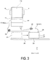
FIG. 3 is a schematic enlarged cross-sectional view of the main part of the cleaning unit according to the first exemplary embodiment as viewed from the Y-axis direction. - Hereinafter, the present disclosure will be schematically described first.
- In order to solve the problems described above, a first aspect of a transport device according to the present disclosure includes a transporting belt having a support face configured to support a medium and configured to transport the medium, a device main body in which the transporting belt is provided, and a cleaning unit configured to clean the support face with a liquid, in which the cleaning unit includes a storage unit in which the liquid is stored, a flow path member through which the liquid discharged from the storage unit and returned to the storage unit passes, and a filter unit detachably provided to the flow path member, and the filter unit is configured to be pulled out in a direction away from the device main body.
- Here, the "device main body" includes a structure in which, for example, a plurality of frames are combined.
- According to this aspect, the filter unit can be pulled out in the direction away from the device main body. As a result, by pulling out the filter unit in the direction away from the device main body, it is possible to move a filter to a position where it is easy to remove the filter from the filter unit. Thus, the workability of replacing the filter by the user can be improved.
- In the first aspect, the transport device according to a second aspect of the present disclosure includes a pump configured to cause the liquid to flow to the storage unit, the filter unit, and the storage unit again, through the flow path member.
- According to this aspect, the pump discharges the liquid from the storage unit, and resupplies the liquid after filtered by the filter unit to the storage unit. This allows the liquid to be reused.
- In the second aspect, the transport device according to a third aspect of the present disclosure includes a valve configured to switch between a first state in which flow of the liquid is permitted and a second state in which the flow of the liquid is restricted, the pump located downstream of the valve in a flow direction of the liquid and being at least one pump, and a control unit configured to control the valve and the pump, in which the control unit, when the filter unit is pulled out from the device main body, switches the valve from the first state to the second state and then stops operating the pump.
- When the filter unit is pulled out from the device main body and the filter is removed from the flow path member, the liquid flowing through the flow path member may leak out.
- According to this aspect, when the control unit determines that the filter unit has been pulled out from the device main body, the control unit switches the valve from the first state of flow allowance to the second state of flow restriction, and then stops operating the pump. Thus, the liquid is first restricted from flowing through the flow path member by the valve, and then stops operating the pump located downstream of the valve. Thereby, the liquid remaining in the flow path member can be removed, that is, the liquid can be drained.
- In the third aspect, the transport device according to a fourth aspect of the present disclosure includes an accommodating unit configured to accommodate the filter.
- According to this aspect, the filter is accommodated in the accommodating unit. Thereby, the filter can be protected from external forces.
- In the transport device according to a fifth aspect of the present disclosure, the accommodating unit in the fourth aspect accommodates the valve and the pump.
- According to this aspect, the valve and the pump are accommodated in the accommodating unit together with the filter. By collecting the filter unit, the valve, and the pump in one place in this way, maintenance is easy.
- In the fourth aspect or the fifth aspect, the transport device according to a sixth aspect of the present disclosure includes an irradiation unit configured to emit light inside the accommodating unit.
- According to this aspect, visibility when removing the filter is improved.
- The transport device according to a seventh aspect of the present disclosure includes, in any one of the first to sixth aspects, a receiving unit configured to receive the liquid from a coupling portion between the flow path member and the filter unit.
- According to this aspect, the transport device includes the receiving unit capable of receiving the liquid from the coupling portion between the flow path member and the filter unit. As a result, when the filter is removed from the flow path member, the liquid that may leak from the coupling portion is received by the receiving unit, so that it is possible to suppress that the surroundings become dirty.
- A recording device according to an eighth aspect of the present disclosure includes a recording unit configured to perform recording on a medium, a transporting belt having a support face configured to support the medium and configured to transport the medium, a device main body in which the transporting belt is provided, and a cleaning unit configured to clean the support face with a liquid, in which the cleaning unit includes a storage unit in which the liquid is stored, a flow path member through which the liquid discharged from the storage unit and returned to the storage unit passes, and a filter unit detachably provided to the flow path member, and the filter unit is configured to be pulled out in a direction away from the device main body.
- According to this aspect, the same effects as those of the first aspect can be obtained as the recording device including the recording unit capable of performing recording on the medium and the transport device.
- Hereinafter, a recording device including a transport device according to a first exemplary embodiment of the present disclosure will be described in detail with reference to
FIGS. 1 to 3 . - In the following description, the three axes orthogonal to each other are the X-axis, the Y-axis, and the Z-axis, respectively, as illustrated in the figures. The Z-axis direction corresponds to the vertical direction (the direction in which gravity acts). The X-axis direction and the Y-axis direction correspond to the horizontal direction. Here, the Y-axis direction corresponds to a medium transport direction, and the X-axis direction corresponds to a width direction of the medium intersecting the transport direction.
- As illustrated in
FIG. 1 , a recording device 1 according to this embodiment is an ink jet printer, and includes a recording unit 3 including an ejecting head for ejecting ink onto a medium P transported in a transport direction (Y-axis direction) F, and atransport device 5 for transporting the medium P. - As illustrated in
FIGS. 1 and2 , thetransport device 5 of this embodiment includes atransporting belt 9 that has asupport face 7 capable of supporting the medium P and is capable of transporting the medium P, a device main body 13 (refer toFIG. 2 ) in which thetransporting belt 9 is provided, and acleaning unit 14 that cleans thesupport face 7 with aliquid 16. - The
cleaning unit 14 includes astorage unit 18 in which theliquid 16 is stored,flow path members liquid 16 discharged from the storage unit and returned to thestorage unit 18 passes, and afilter unit 21 detachably provided to theflow path members filter unit 21 is configured to be able to be pulled out in a direction away from the device main body 13. - Components of the
transport device 5 will be described below. - As illustrated in
FIG. 1 , thetransporting belt 9 is an endless belt that is stretched between adrive roller 4 and a drivenroller 6. Anadhesive layer 8 is provided on thesupport face 7 serving as the outer peripheral surface of theendless transporting belt 9. The medium P is attached to theadhesive layer 8 by an attaching member (not illustrated), and passes through a recording execution region of the recording unit 3 in an attached state. Ink is attached to thesupport face 7 of thetransporting belt 9 due to the recording operation of the recording unit 3. Thecleaning unit 14 for cleaning thesupport face 7 on which the ink is attached is arranged in the vicinity of thedrive roller 4 as described above. - The medium P is a common sheet-shaped recording medium, such as paper, fabric, or plastic film, for recording by an ink jet printer.
- The device main body 13 means a structure having a framework of the device as a main part, which is constituted of a plurality of frames 22.
- In the recording device 1, constituent members such as the recording unit 3, the
transport device 5, and thecleaning unit 14 are attached to the device main body 13 as a basic structure. Further, the recording device 1 is covered with a housing (not illustrated) to configure an appearance. - The
cleaning unit 14 includes thestorage unit 18 that stores the liquid 16 for cleaning, abrush roller 20 that is half immersed in the liquid 16, and a wiping unit 2 that wipes thesupport face 7 of the transportingbelt 9 with awiper 11. The wiping unit 2 is supported inside thestorage unit 18. - As illustrated in
FIG. 1 , thecleaning unit 14 is arranged in the vicinity of thedrive roller 4 for the transportingbelt 9. Thesupport face 7 of the transportingbelt 9 is first brush-cleaned by the rotational contact of thebrush roller 20. Subsequently, when the transportingbelt 9 passes through on the wiping unit 2, thesupport face 7 of the transportingbelt 9 is wiped by thewiper 11. The liquid 16 in the storage unit 18gradually becomes dirty due to this cleaning and wiping. - As described above, the
flow path members storage unit 18. The liquid 16 in thestorage unit 18 is discharged to the outside of thestorage unit 18 through the oneflow path member 15 that is coupled to the bottom side of thestorage unit 18, and is fed to thefilter unit 21. The liquid 16 is filtered by afilter 23 of thefilter unit 21 and converted into apurified liquid 162, and is returned to thestorage unit 18 from above through the otherflow path member 17. The liquid 16 before being filtered by thefilter unit 21 is referred to here as adirty liquid 161 in contrast to the purifiedliquid 162. - The
filter unit 21 is detachably coupled to theflow path members - In addition, as illustrated in
FIGS. 2 and3 , thefilter unit 21 is configured to be able to be pulled out in the direction away from the device main body 13 (X-axis direction), that is, in the width direction of the transportingbelt 9. In other words, thefilter unit 21 is configured to be able to be pulled out in the width direction of the transportingbelt 9 for the transportingbelt 9. - In this embodiment, pumps 25 and 31 are provided in a liquid flow path created by the
flow path members pumps flow path members storage unit 18, thefilter unit 21, and again thestorage unit 18. In this embodiment, twopumps supply head 27, such as a nozzle, is provided at a portion where the purifiedliquid 162 after filtered by thefilter unit 21 is supplied from theflow path member 17 into thestorage unit 18. - In this embodiment, a
valve 29, such as an electromagnetic valve, is provided in the liquid flow path. Thevalve 29 can switch between a first state in which the flow of the liquid 16 is permitted and a second state in which the flow of the liquid 16 is restricted. Further, of thepumps pump 31 is located downstream of thevalve 29 in the flow direction of the liquid 16. In this embodiment, thepump 31 is attached to the device main body 13. - As illustrated in
FIG. 2 , thefilter unit 21 includes anaccommodating unit 37 that accommodates thefilter 23. Theaccommodating unit 37 is configured to accommodate further thevalve 29 and the onepump 25. Specifically, thevalve 29 and thepump 25 are respectively arranged at the upper edge portion of theaccommodating unit 37. - Note that the
pump 31 may also be accommodated in theaccommodating unit 37 without being attached to the device main body 13. In that case, the arrangement of thevalve 29 also needs to be changed so that thepump 31 is located downstream of thevalve 29. - The operation of the
valve 29 and the operations of thepumps control unit 33. In this embodiment, when thefilter unit 21 is pulled out from the device main body 13, thecontrol unit 33 is configured to switch thevalve 29 from the first state to the second state to restrict the flow of the liquid 16 and then stop the operation of thepump 31 located downstream of thevalve 29. - Whether the
filter unit 21 is pulled out from the device main body 13 is determined by providing a dedicated detection sensor (not illustrated). - As the detection sensor, for example, an optical sensor may be employed. Examples of the optical sensor include a light emitting diode (LED) as a light emitting element and a phototransistor as a photodetector. The detection sensor is fixed to the device main body 13. Specifically, in a state in which the
filter unit 21 is accommodated in the device main body 13, the light emitting element is arranged so as to face the photodetector with thefilter unit 21 interposed therebetween. In addition, in the state in which thefilter unit 21 is accommodated in the device main body 13, the positional relationship between thefilter unit 21 and the detection sensor is adjusted so that thefilter unit 21 is located in the middle of the path of the light emitted from the light emitting element. At this time, the path of the light preferably intersects the moving direction of thefilter unit 21. In other words, in the state in which thefilter unit 21 is accommodated in the device main body 13, the light emitted from the light emitting element is blocked by thefilter unit 21, whereby the light is set so as not enter the photodetector. Thecontrol unit 33 can determine that thefilter unit 21 is accommodated in the device main body 13 by detecting that the light emitted from the light emitting element is blocked by thefilter unit 21 by using the detection sensor. On the other hand, when thefilter unit 21 is pulled out in the direction away from the device main body 13, thefilter unit 21 moves out from the path of the light emitted from the light emitting element so that the light is incident on the photodetector. Thecontrol unit 33 can determine that thefilter unit 21 is pulled out in the direction away from the device main body 13 due to the light emitted from the light emitting element being incident on the photodetector. Although the above description is for the case in which the detection sensor is a transmissive optical sensor, the detection sensor can be a reflective optical sensor. In a case of the reflective optical sensor, the light emitting element is provided on the same side as the photodetector. Then, based on the presence or absence of the reflected light from thefilter unit 21, thecontrol unit 33 can determine whether thefilter unit 21 is pulled out from the device main body 13. - Note that the determination may be performed by switch operation by the user instead of the dedicated detection sensor. In this case, the switch is electrically coupled to the
control unit 33. Alternatively, a touch panel may be provided on the recording device 1 (transport device 5), and the user may input that thefilter unit 21 is pulled out in the direction away from the device main body 13 via the touch panel. In this case, the touch panel is electrically coupled to thecontrol unit 33. - As illustrated in
FIGS. 2 and3 , thefilter unit 21 is provided with a pair of protrudingbars accommodating unit 37. The pair of protrudingbars rails filter unit 21 is configured to be movable in the pull-out direction. - The
flow path members coil portions coil portions flow path members filter unit 21 is pulled out in the direction away from the device main body 13 (in the X-axis direction), thecoil portions filter unit 21 moves toward the device main body 13, thecoil portions - Note that, instead of the
coil portions flow path members flow path members filter portion 21 is pulled out. - In this embodiment, as illustrated in
FIG. 2 , anirradiation unit 39 that emits light is provided inside theaccommodating unit 37. Theirradiation unit 39 is used as illumination that brightens the coupling portions between theflow path members filter 23. As theirradiation unit 39, for example, an LED lamp or a light bulb capable of emitting visible light can be used. When thecontrol unit 33 determines that thefilter unit 21 has been pulled out from the device main body 13, theirradiation unit 39 may start emitting visible light. In other words, when thefilter unit 21 is pulled out from the device main body 13, thecontrol unit 33 may start emitting visible light by theirradiation unit 39. As a result, the power consumption of theirradiation unit 39 can be reduced. - Further, receiving
units flow path members filter 23 are provided. The receivingunits liquid 16, and preferably have an absorber (not illustrated) that absorbs the liquid. Furthermore, the receivingunit 35 and the absorber are preferably replaceable. - Next, based on
FIGS. 1 to 3 , the following effects can be obtained when thefilter 23 is replaced in the recording device 1 provided with thetransport device 5 according to the first exemplary embodiment. - (1) According to this embodiment, as illustrated in
FIG. 3 , thefilter unit 21 can be pulled out in the direction away from the device main body 13. As a result, by pulling out thefilter unit 21 in the direction away from the device main body 13, it is possible to move thefilter 23 to a position where the work for removing thefilter 23 from thefilter unit 21 can be easily performed. Thus, the workability of replacing thefilter 23 by the user can be improved. - (2) The
pumps storage unit 18, and resupply the purifiedliquid 162, which is the liquid 16 after the liquid 16 has been filtered by thefilter unit 21, to thestorage unit 18. This allows the liquid 16 to be reused. - (3) When the
filter unit 21 is pulled out from the device main body 13 and thefilter 23 is removed from theflow path members flow path members - According to this embodiment, when the
control unit 33 determines that thefilter unit 21 has been pulled out from the device main body 13, thecontrol unit 33 switches thevalve 29 from the first state of flow allowance to the second state of flow restriction, and then stops the operation of thepump 31 located downstream of thevalve 29. In this way, the fluid 16 is first restricted from flowing theflow path members valve 29, and then the operation of thepump 31 located downstream of thevalve 29 is stopped, so that the liquid 16 remaining in theflow path members - (4) The
filter 23 is accommodated in theaccommodating unit 37. In this way, it is possible to reduce the possibility that thefilter 23 unintentionally disengages from theflow path members filter 23 when the user inadvertently touches thefilter 23, for example. In other words, thefilter 23 can be protected from the external force. - (5) The
filter 23, thevalve 29, and thepump 25 are accommodated in theaccommodating unit 37. In this way, maintenance is facilitated by collecting thefilter 23, thevalve 29, and thepump 25 in one place. - (6) Since the
irradiation unit 39 that emits light is provided inside theaccommodating unit 37, the visibility when removing thefilter 23 is improved. - (7) The receiving
units flow path members filter unit 21 are provided. As a result, when thefilter 23 is removed from theflow path members respective receiving units - The recording device 1 including the
transport device 5 according to the exemplary embodiment of the present disclosure is based on the configuration described above. However, as a matter of course, partial configurations may be modified or omitted without departing from the gist of the disclosure of the present application. - For example, a detection unit that detects the level of dirt of the
filter 23 may be provided. - The detection sensor may not be an optical sensor. The detection sensor may be an ultrasonic sensor or a mechanical sensor such as a microswitch.
Claims (8)
- A transport device comprising:a transporting belt having a support face configured to support a medium and configured to transport the medium;a device main body in which the transporting belt is provided; anda cleaning unit configured to clean the support face with a liquid, whereinthe cleaning unit includesa storage unit in which the liquid is stored,a flow path member through which the liquid discharged from the storage unit and returned to the storage unit passes, anda filter unit including a filter detachably coupled to the flow path member, andthe filter unit is configured to be pulled out in a direction away from the device main body.
- The transport device according to claim 1, comprising
a pump configured to cause the liquid to flow to the storage unit, the filter unit, and the storage unit again, via the flow path member. - The transport device according to claim 2, comprising:a valve configured to switch between a first state in which the flow of the liquid is permitted and a second state in which the flow of the liquid is restricted;the pump located downstream of the valve in a flow direction of the liquid, the number of the pump being one or more; anda control unit configured to control the valve and the pump, whereinthe control unit, when the filter unit is pulled out from the device main body, switches the valve from the first state to the second state and then stops operation of the pump located downstream of the valve.
- The transport device according to any one of claims 1 to 3, wherein
the filter unit includes an accommodating unit configured to accommodate the filter. - The transport device according to claim 4, wherein
the accommodating unit accommodates the valve and the pump. - The transport device according to claim 4 or 5, comprising an irradiation unit configured to emit light inside the accommodating unit.
- The transport device according to any one of claims 1 to 6, comprising
a receiving unit configured to receive the liquid from a coupling portion between the flow path member and the filter. - A recording device comprising:a recording unit configured to perform recording on a medium;a transporting belt having a support face configured to support the medium and configured to transport the medium;a device main body in which the transporting belt is provided; anda cleaning unit configured to clean the support face with a liquid, whereinthe cleaning unit includesa storage unit in which the liquid is stored,a flow path member through which the liquid discharged from the storage unit and returned to the storage unit passes, anda filter unit detachably provided to the flow path member, andthe filter unit is configured to be pulled out in a direction away from the device main body.
Applications Claiming Priority (1)
| Application Number | Priority Date | Filing Date | Title |
|---|---|---|---|
| JP2020216435A JP7631796B2 (en) | 2020-12-25 | 2020-12-25 | Conveying device and recording device |
Publications (2)
| Publication Number | Publication Date |
|---|---|
| EP4019442A1 true EP4019442A1 (en) | 2022-06-29 |
| EP4019442B1 EP4019442B1 (en) | 2023-11-01 |
Family
ID=79021895
Family Applications (1)
| Application Number | Title | Priority Date | Filing Date |
|---|---|---|---|
| EP21217311.6A Active EP4019442B1 (en) | 2020-12-25 | 2021-12-23 | Transport device and recording device |
Country Status (4)
| Country | Link |
|---|---|
| US (1) | US12053993B2 (en) |
| EP (1) | EP4019442B1 (en) |
| JP (1) | JP7631796B2 (en) |
| CN (1) | CN114684636B (en) |
Families Citing this family (4)
| Publication number | Priority date | Publication date | Assignee | Title |
|---|---|---|---|---|
| EP3915905A1 (en) * | 2020-05-29 | 2021-12-01 | Bühler AG | Drive unit |
| JP2024122013A (en) * | 2023-02-28 | 2024-09-09 | セイコーエプソン株式会社 | Conveying device and recording device |
| JP7612128B1 (en) * | 2023-06-05 | 2025-01-10 | 京セラ株式会社 | Printing device |
| CN118873708B (en) * | 2024-09-24 | 2025-01-21 | 温州泰星皮革制品有限公司 | A leather belt processing and sterilization equipment |
Citations (4)
| Publication number | Priority date | Publication date | Assignee | Title |
|---|---|---|---|---|
| JP2002296921A (en) * | 2001-03-30 | 2002-10-09 | Kanegafuchi Chem Ind Co Ltd | Image forming device |
| US20090244247A1 (en) * | 2008-03-27 | 2009-10-01 | Brother Kogyo Kabushiki Kaisha | Inkjet Recording Apparatus |
| JP2009241285A (en) | 2008-03-28 | 2009-10-22 | Konica Minolta Ij Technologies Inc | Recording medium transport device and inkjet recorder |
| US20190275799A1 (en) * | 2018-03-07 | 2019-09-12 | Seiko Epson Corporation | Liquid ejecting apparatus and liquid ejecting apparatus maintenance method |
Family Cites Families (14)
| Publication number | Priority date | Publication date | Assignee | Title |
|---|---|---|---|---|
| US5751307A (en) * | 1994-04-12 | 1998-05-12 | Moore Business Forms, Inc. | Print cartridge cleaning apparatus and method using water and air |
| US7468082B2 (en) * | 2004-04-28 | 2008-12-23 | Gordon Robert R | Self cleaning gas filtering system and method |
| JP4389850B2 (en) * | 2005-07-22 | 2009-12-24 | コニカミノルタホールディングス株式会社 | Inkjet recording device |
| JP4811238B2 (en) * | 2006-11-06 | 2011-11-09 | コニカミノルタホールディングス株式会社 | Inkjet recording device |
| JP4309437B2 (en) * | 2007-03-07 | 2009-08-05 | 京セラミタ株式会社 | Inkjet recording device |
| JP5198975B2 (en) * | 2008-08-29 | 2013-05-15 | 株式会社ミマキエンジニアリング | Cleaning mechanism |
| JP2014172327A (en) * | 2013-03-11 | 2014-09-22 | Seiko Epson Corp | Recording device and recording method |
| JP6263879B2 (en) * | 2013-07-09 | 2018-01-24 | セイコーエプソン株式会社 | Liquid ejector |
| JP6296224B2 (en) * | 2013-10-04 | 2018-03-20 | セイコーエプソン株式会社 | Recording apparatus and conveying belt cleaning method |
| JP6322977B2 (en) * | 2013-11-29 | 2018-05-16 | セイコーエプソン株式会社 | Recording device |
| JP6013671B2 (en) * | 2014-10-15 | 2016-10-25 | オリンパス株式会社 | Cleaning tool for insertion equipment |
| CN105540313B (en) * | 2015-12-09 | 2016-12-07 | 北京巨维通科技有限公司 | A kind of haze filter of belt tension adjusting means |
| JP7127433B2 (en) * | 2018-08-30 | 2022-08-30 | セイコーエプソン株式会社 | LIQUID EJECTING DEVICE, MAINTENANCE METHOD OF LIQUID EJECTING DEVICE |
| JP7518475B2 (en) * | 2020-07-31 | 2024-07-18 | セイコーエプソン株式会社 | Recording device and method for reversely transporting a recording medium |
-
2020
- 2020-12-25 JP JP2020216435A patent/JP7631796B2/en active Active
-
2021
- 2021-12-22 US US17/558,743 patent/US12053993B2/en active Active
- 2021-12-22 CN CN202111578518.XA patent/CN114684636B/en active Active
- 2021-12-23 EP EP21217311.6A patent/EP4019442B1/en active Active
Patent Citations (4)
| Publication number | Priority date | Publication date | Assignee | Title |
|---|---|---|---|---|
| JP2002296921A (en) * | 2001-03-30 | 2002-10-09 | Kanegafuchi Chem Ind Co Ltd | Image forming device |
| US20090244247A1 (en) * | 2008-03-27 | 2009-10-01 | Brother Kogyo Kabushiki Kaisha | Inkjet Recording Apparatus |
| JP2009241285A (en) | 2008-03-28 | 2009-10-22 | Konica Minolta Ij Technologies Inc | Recording medium transport device and inkjet recorder |
| US20190275799A1 (en) * | 2018-03-07 | 2019-09-12 | Seiko Epson Corporation | Liquid ejecting apparatus and liquid ejecting apparatus maintenance method |
Also Published As
| Publication number | Publication date |
|---|---|
| JP2022101995A (en) | 2022-07-07 |
| US20220203732A1 (en) | 2022-06-30 |
| CN114684636A (en) | 2022-07-01 |
| EP4019442B1 (en) | 2023-11-01 |
| JP7631796B2 (en) | 2025-02-19 |
| US12053993B2 (en) | 2024-08-06 |
| CN114684636B (en) | 2026-05-05 |
Similar Documents
| Publication | Publication Date | Title |
|---|---|---|
| US12053993B2 (en) | Transport device and recording device | |
| JP5962661B2 (en) | Inkjet recording device | |
| JP5917083B2 (en) | Inkjet recording apparatus and maintenance method | |
| EP2325012A1 (en) | Ink supply circuit | |
| JP6682376B2 (en) | Inkjet recording device | |
| JP2013067032A (en) | Ink supply device of inkjet recording apparatus and ink supply method | |
| JP2005319650A (en) | Droplet ejection device and cartridge | |
| JP2020069676A (en) | Liquid jet device, maintenance method of the liquid jet device | |
| JP2019155597A (en) | Liquid injection device and maintenance method for liquid injection device | |
| JP2015168080A (en) | Liquid ejecting apparatus and maintenance method | |
| US20230321986A1 (en) | Liquid discharge apparatus, waste liquid collecting unit, and waste liquid collecting method | |
| JP6950510B2 (en) | Manufacturing method of flow path member, liquid injection device and flow path member | |
| KR20140029311A (en) | Apparatus for cleaning belt, apparatus for transfering medium and inkjet recording apparatus | |
| US20080316251A1 (en) | Print head cleaning device and ink-jet image forming apparatus having the same | |
| CN118144427A (en) | Liquid spraying device | |
| JP5440581B2 (en) | Inkjet recording device | |
| CN116766767A (en) | Liquid ejecting apparatus, waste liquid recovery unit, and waste liquid recovery method | |
| CN112644174B (en) | Liquid storage container and liquid ejecting apparatus | |
| US12528294B2 (en) | Liquid ejection device | |
| JP6379948B2 (en) | Liquid ejection device | |
| US20240326453A1 (en) | Control method of liquid discharge apparatus and liquid discharge apparatus | |
| JP7323029B2 (en) | LIQUID EJECTING DEVICE, MAINTENANCE METHOD OF LIQUID EJECTING DEVICE | |
| CN113771501B (en) | Liquid ejection device and control method of liquid ejection device | |
| JP6372080B2 (en) | Image forming apparatus | |
| CN109649007B (en) | liquid ejection device |
Legal Events
| Date | Code | Title | Description |
|---|---|---|---|
| PUAI | Public reference made under article 153(3) epc to a published international application that has entered the european phase |
Free format text: ORIGINAL CODE: 0009012 |
|
| STAA | Information on the status of an ep patent application or granted ep patent |
Free format text: STATUS: THE APPLICATION HAS BEEN PUBLISHED |
|
| AK | Designated contracting states |
Kind code of ref document: A1 Designated state(s): AL AT BE BG CH CY CZ DE DK EE ES FI FR GB GR HR HU IE IS IT LI LT LU LV MC MK MT NL NO PL PT RO RS SE SI SK SM TR |
|
| STAA | Information on the status of an ep patent application or granted ep patent |
Free format text: STATUS: REQUEST FOR EXAMINATION WAS MADE |
|
| 17P | Request for examination filed |
Effective date: 20221104 |
|
| RBV | Designated contracting states (corrected) |
Designated state(s): AL AT BE BG CH CY CZ DE DK EE ES FI FR GB GR HR HU IE IS IT LI LT LU LV MC MK MT NL NO PL PT RO RS SE SI SK SM TR |
|
| GRAP | Despatch of communication of intention to grant a patent |
Free format text: ORIGINAL CODE: EPIDOSNIGR1 |
|
| STAA | Information on the status of an ep patent application or granted ep patent |
Free format text: STATUS: GRANT OF PATENT IS INTENDED |
|
| INTG | Intention to grant announced |
Effective date: 20230524 |
|
| GRAS | Grant fee paid |
Free format text: ORIGINAL CODE: EPIDOSNIGR3 |
|
| GRAA | (expected) grant |
Free format text: ORIGINAL CODE: 0009210 |
|
| STAA | Information on the status of an ep patent application or granted ep patent |
Free format text: STATUS: THE PATENT HAS BEEN GRANTED |
|
| AK | Designated contracting states |
Kind code of ref document: B1 Designated state(s): AL AT BE BG CH CY CZ DE DK EE ES FI FR GB GR HR HU IE IS IT LI LT LU LV MC MK MT NL NO PL PT RO RS SE SI SK SM TR |
|
| REG | Reference to a national code |
Ref country code: GB Ref legal event code: FG4D |
|
| REG | Reference to a national code |
Ref country code: CH Ref legal event code: EP |
|
| REG | Reference to a national code |
Ref country code: IE Ref legal event code: FG4D |
|
| REG | Reference to a national code |
Ref country code: DE Ref legal event code: R096 Ref document number: 602021006426 Country of ref document: DE |
|
| REG | Reference to a national code |
Ref country code: LT Ref legal event code: MG9D |
|
| REG | Reference to a national code |
Ref country code: NL Ref legal event code: MP Effective date: 20231101 |
|
| PG25 | Lapsed in a contracting state [announced via postgrant information from national office to epo] |
Ref country code: GR Free format text: LAPSE BECAUSE OF FAILURE TO SUBMIT A TRANSLATION OF THE DESCRIPTION OR TO PAY THE FEE WITHIN THE PRESCRIBED TIME-LIMIT Effective date: 20240202 |
|
| PG25 | Lapsed in a contracting state [announced via postgrant information from national office to epo] |
Ref country code: IS Free format text: LAPSE BECAUSE OF FAILURE TO SUBMIT A TRANSLATION OF THE DESCRIPTION OR TO PAY THE FEE WITHIN THE PRESCRIBED TIME-LIMIT Effective date: 20240301 |
|
| PG25 | Lapsed in a contracting state [announced via postgrant information from national office to epo] |
Ref country code: LT Free format text: LAPSE BECAUSE OF FAILURE TO SUBMIT A TRANSLATION OF THE DESCRIPTION OR TO PAY THE FEE WITHIN THE PRESCRIBED TIME-LIMIT Effective date: 20231101 |
|
| REG | Reference to a national code |
Ref country code: AT Ref legal event code: MK05 Ref document number: 1627016 Country of ref document: AT Kind code of ref document: T Effective date: 20231101 |
|
| PG25 | Lapsed in a contracting state [announced via postgrant information from national office to epo] |
Ref country code: NL Free format text: LAPSE BECAUSE OF FAILURE TO SUBMIT A TRANSLATION OF THE DESCRIPTION OR TO PAY THE FEE WITHIN THE PRESCRIBED TIME-LIMIT Effective date: 20231101 |
|
| PG25 | Lapsed in a contracting state [announced via postgrant information from national office to epo] |
Ref country code: AT Free format text: LAPSE BECAUSE OF FAILURE TO SUBMIT A TRANSLATION OF THE DESCRIPTION OR TO PAY THE FEE WITHIN THE PRESCRIBED TIME-LIMIT Effective date: 20231101 |
|
| PG25 | Lapsed in a contracting state [announced via postgrant information from national office to epo] |
Ref country code: ES Free format text: LAPSE BECAUSE OF FAILURE TO SUBMIT A TRANSLATION OF THE DESCRIPTION OR TO PAY THE FEE WITHIN THE PRESCRIBED TIME-LIMIT Effective date: 20231101 |
|
| PG25 | Lapsed in a contracting state [announced via postgrant information from national office to epo] |
Ref country code: NL Free format text: LAPSE BECAUSE OF FAILURE TO SUBMIT A TRANSLATION OF THE DESCRIPTION OR TO PAY THE FEE WITHIN THE PRESCRIBED TIME-LIMIT Effective date: 20231101 Ref country code: LT Free format text: LAPSE BECAUSE OF FAILURE TO SUBMIT A TRANSLATION OF THE DESCRIPTION OR TO PAY THE FEE WITHIN THE PRESCRIBED TIME-LIMIT Effective date: 20231101 Ref country code: IS Free format text: LAPSE BECAUSE OF FAILURE TO SUBMIT A TRANSLATION OF THE DESCRIPTION OR TO PAY THE FEE WITHIN THE PRESCRIBED TIME-LIMIT Effective date: 20240301 Ref country code: GR Free format text: LAPSE BECAUSE OF FAILURE TO SUBMIT A TRANSLATION OF THE DESCRIPTION OR TO PAY THE FEE WITHIN THE PRESCRIBED TIME-LIMIT Effective date: 20240202 Ref country code: ES Free format text: LAPSE BECAUSE OF FAILURE TO SUBMIT A TRANSLATION OF THE DESCRIPTION OR TO PAY THE FEE WITHIN THE PRESCRIBED TIME-LIMIT Effective date: 20231101 Ref country code: BG Free format text: LAPSE BECAUSE OF FAILURE TO SUBMIT A TRANSLATION OF THE DESCRIPTION OR TO PAY THE FEE WITHIN THE PRESCRIBED TIME-LIMIT Effective date: 20240201 Ref country code: AT Free format text: LAPSE BECAUSE OF FAILURE TO SUBMIT A TRANSLATION OF THE DESCRIPTION OR TO PAY THE FEE WITHIN THE PRESCRIBED TIME-LIMIT Effective date: 20231101 Ref country code: PT Free format text: LAPSE BECAUSE OF FAILURE TO SUBMIT A TRANSLATION OF THE DESCRIPTION OR TO PAY THE FEE WITHIN THE PRESCRIBED TIME-LIMIT Effective date: 20240301 |
|
| PG25 | Lapsed in a contracting state [announced via postgrant information from national office to epo] |
Ref country code: SE Free format text: LAPSE BECAUSE OF FAILURE TO SUBMIT A TRANSLATION OF THE DESCRIPTION OR TO PAY THE FEE WITHIN THE PRESCRIBED TIME-LIMIT Effective date: 20231101 Ref country code: RS Free format text: LAPSE BECAUSE OF FAILURE TO SUBMIT A TRANSLATION OF THE DESCRIPTION OR TO PAY THE FEE WITHIN THE PRESCRIBED TIME-LIMIT Effective date: 20231101 Ref country code: PL Free format text: LAPSE BECAUSE OF FAILURE TO SUBMIT A TRANSLATION OF THE DESCRIPTION OR TO PAY THE FEE WITHIN THE PRESCRIBED TIME-LIMIT Effective date: 20231101 Ref country code: NO Free format text: LAPSE BECAUSE OF FAILURE TO SUBMIT A TRANSLATION OF THE DESCRIPTION OR TO PAY THE FEE WITHIN THE PRESCRIBED TIME-LIMIT Effective date: 20240201 Ref country code: LV Free format text: LAPSE BECAUSE OF FAILURE TO SUBMIT A TRANSLATION OF THE DESCRIPTION OR TO PAY THE FEE WITHIN THE PRESCRIBED TIME-LIMIT Effective date: 20231101 Ref country code: HR Free format text: LAPSE BECAUSE OF FAILURE TO SUBMIT A TRANSLATION OF THE DESCRIPTION OR TO PAY THE FEE WITHIN THE PRESCRIBED TIME-LIMIT Effective date: 20231101 |
|
| REG | Reference to a national code |
Ref country code: DE Ref legal event code: R119 Ref document number: 602021006426 Country of ref document: DE |
|
| PG25 | Lapsed in a contracting state [announced via postgrant information from national office to epo] |
Ref country code: DK Free format text: LAPSE BECAUSE OF FAILURE TO SUBMIT A TRANSLATION OF THE DESCRIPTION OR TO PAY THE FEE WITHIN THE PRESCRIBED TIME-LIMIT Effective date: 20231101 |
|
| PG25 | Lapsed in a contracting state [announced via postgrant information from national office to epo] |
Ref country code: CZ Free format text: LAPSE BECAUSE OF FAILURE TO SUBMIT A TRANSLATION OF THE DESCRIPTION OR TO PAY THE FEE WITHIN THE PRESCRIBED TIME-LIMIT Effective date: 20231101 |
|
| PG25 | Lapsed in a contracting state [announced via postgrant information from national office to epo] |
Ref country code: SK Free format text: LAPSE BECAUSE OF FAILURE TO SUBMIT A TRANSLATION OF THE DESCRIPTION OR TO PAY THE FEE WITHIN THE PRESCRIBED TIME-LIMIT Effective date: 20231101 |
|
| PG25 | Lapsed in a contracting state [announced via postgrant information from national office to epo] |
Ref country code: SM Free format text: LAPSE BECAUSE OF FAILURE TO SUBMIT A TRANSLATION OF THE DESCRIPTION OR TO PAY THE FEE WITHIN THE PRESCRIBED TIME-LIMIT Effective date: 20231101 Ref country code: SK Free format text: LAPSE BECAUSE OF FAILURE TO SUBMIT A TRANSLATION OF THE DESCRIPTION OR TO PAY THE FEE WITHIN THE PRESCRIBED TIME-LIMIT Effective date: 20231101 Ref country code: IT Free format text: LAPSE BECAUSE OF NON-PAYMENT OF DUE FEES Effective date: 20231223 Ref country code: EE Free format text: LAPSE BECAUSE OF FAILURE TO SUBMIT A TRANSLATION OF THE DESCRIPTION OR TO PAY THE FEE WITHIN THE PRESCRIBED TIME-LIMIT Effective date: 20231101 Ref country code: DK Free format text: LAPSE BECAUSE OF FAILURE TO SUBMIT A TRANSLATION OF THE DESCRIPTION OR TO PAY THE FEE WITHIN THE PRESCRIBED TIME-LIMIT Effective date: 20231101 Ref country code: CZ Free format text: LAPSE BECAUSE OF FAILURE TO SUBMIT A TRANSLATION OF THE DESCRIPTION OR TO PAY THE FEE WITHIN THE PRESCRIBED TIME-LIMIT Effective date: 20231101 |
|
| PG25 | Lapsed in a contracting state [announced via postgrant information from national office to epo] |
Ref country code: LU Free format text: LAPSE BECAUSE OF NON-PAYMENT OF DUE FEES Effective date: 20231223 |
|
| PG25 | Lapsed in a contracting state [announced via postgrant information from national office to epo] |
Ref country code: MC Free format text: LAPSE BECAUSE OF FAILURE TO SUBMIT A TRANSLATION OF THE DESCRIPTION OR TO PAY THE FEE WITHIN THE PRESCRIBED TIME-LIMIT Effective date: 20231101 |
|
| REG | Reference to a national code |
Ref country code: BE Ref legal event code: MM Effective date: 20231231 |
|
| PG25 | Lapsed in a contracting state [announced via postgrant information from national office to epo] |
Ref country code: MC Free format text: LAPSE BECAUSE OF FAILURE TO SUBMIT A TRANSLATION OF THE DESCRIPTION OR TO PAY THE FEE WITHIN THE PRESCRIBED TIME-LIMIT Effective date: 20231101 Ref country code: LU Free format text: LAPSE BECAUSE OF NON-PAYMENT OF DUE FEES Effective date: 20231223 |
|
| PLBE | No opposition filed within time limit |
Free format text: ORIGINAL CODE: 0009261 |
|
| STAA | Information on the status of an ep patent application or granted ep patent |
Free format text: STATUS: NO OPPOSITION FILED WITHIN TIME LIMIT |
|
| 26N | No opposition filed |
Effective date: 20240802 |
|
| REG | Reference to a national code |
Ref country code: IE Ref legal event code: MM4A |
|
| PG25 | Lapsed in a contracting state [announced via postgrant information from national office to epo] |
Ref country code: DE Free format text: LAPSE BECAUSE OF NON-PAYMENT OF DUE FEES Effective date: 20240702 Ref country code: IE Free format text: LAPSE BECAUSE OF NON-PAYMENT OF DUE FEES Effective date: 20231223 |
|
| PG25 | Lapsed in a contracting state [announced via postgrant information from national office to epo] |
Ref country code: BE Free format text: LAPSE BECAUSE OF NON-PAYMENT OF DUE FEES Effective date: 20231231 |
|
| PG25 | Lapsed in a contracting state [announced via postgrant information from national office to epo] |
Ref country code: FR Free format text: LAPSE BECAUSE OF NON-PAYMENT OF DUE FEES Effective date: 20240101 |
|
| PG25 | Lapsed in a contracting state [announced via postgrant information from national office to epo] |
Ref country code: SI Free format text: LAPSE BECAUSE OF FAILURE TO SUBMIT A TRANSLATION OF THE DESCRIPTION OR TO PAY THE FEE WITHIN THE PRESCRIBED TIME-LIMIT Effective date: 20231101 |
|
| PG25 | Lapsed in a contracting state [announced via postgrant information from national office to epo] |
Ref country code: SI Free format text: LAPSE BECAUSE OF FAILURE TO SUBMIT A TRANSLATION OF THE DESCRIPTION OR TO PAY THE FEE WITHIN THE PRESCRIBED TIME-LIMIT Effective date: 20231101 Ref country code: IE Free format text: LAPSE BECAUSE OF NON-PAYMENT OF DUE FEES Effective date: 20231223 Ref country code: FR Free format text: LAPSE BECAUSE OF NON-PAYMENT OF DUE FEES Effective date: 20240101 Ref country code: DE Free format text: LAPSE BECAUSE OF NON-PAYMENT OF DUE FEES Effective date: 20240702 Ref country code: BE Free format text: LAPSE BECAUSE OF NON-PAYMENT OF DUE FEES Effective date: 20231231 |
|
| PG25 | Lapsed in a contracting state [announced via postgrant information from national office to epo] |
Ref country code: IT Free format text: LAPSE BECAUSE OF NON-PAYMENT OF DUE FEES Effective date: 20231223 |
|
| PGRI | Patent reinstated in contracting state [announced from national office to epo] |
Ref country code: IT Effective date: 20240102 |
|
| PG25 | Lapsed in a contracting state [announced via postgrant information from national office to epo] |
Ref country code: IT Free format text: LAPSE BECAUSE OF NON-PAYMENT OF DUE FEES Effective date: 20231223 |
|
| PGRI | Patent reinstated in contracting state [announced from national office to epo] |
Ref country code: IT Effective date: 20240102 |
|
| PG25 | Lapsed in a contracting state [announced via postgrant information from national office to epo] |
Ref country code: RO Free format text: LAPSE BECAUSE OF FAILURE TO SUBMIT A TRANSLATION OF THE DESCRIPTION OR TO PAY THE FEE WITHIN THE PRESCRIBED TIME-LIMIT Effective date: 20231101 |
|
| PG25 | Lapsed in a contracting state [announced via postgrant information from national office to epo] |
Ref country code: FI Free format text: LAPSE BECAUSE OF FAILURE TO SUBMIT A TRANSLATION OF THE DESCRIPTION OR TO PAY THE FEE WITHIN THE PRESCRIBED TIME-LIMIT Effective date: 20231101 |
|
| PG25 | Lapsed in a contracting state [announced via postgrant information from national office to epo] |
Ref country code: CY Free format text: LAPSE BECAUSE OF FAILURE TO SUBMIT A TRANSLATION OF THE DESCRIPTION OR TO PAY THE FEE WITHIN THE PRESCRIBED TIME-LIMIT; INVALID AB INITIO Effective date: 20211223 |
|
| REG | Reference to a national code |
Ref country code: CH Ref legal event code: PL |
|
| PG25 | Lapsed in a contracting state [announced via postgrant information from national office to epo] |
Ref country code: CH Free format text: LAPSE BECAUSE OF NON-PAYMENT OF DUE FEES Effective date: 20241231 |
|
| PG25 | Lapsed in a contracting state [announced via postgrant information from national office to epo] |
Ref country code: TR Free format text: LAPSE BECAUSE OF FAILURE TO SUBMIT A TRANSLATION OF THE DESCRIPTION OR TO PAY THE FEE WITHIN THE PRESCRIBED TIME-LIMIT Effective date: 20231101 |
|
| PGFP | Annual fee paid to national office [announced via postgrant information from national office to epo] |
Ref country code: IT Payment date: 20251223 Year of fee payment: 5 |
|
| PG25 | Lapsed in a contracting state [announced via postgrant information from national office to epo] |
Ref country code: HU Free format text: LAPSE BECAUSE OF FAILURE TO SUBMIT A TRANSLATION OF THE DESCRIPTION OR TO PAY THE FEE WITHIN THE PRESCRIBED TIME-LIMIT; INVALID AB INITIO Effective date: 20211223 |