EP4019308B1 - Electric wheel hub - Google Patents
Electric wheel hub Download PDFInfo
- Publication number
- EP4019308B1 EP4019308B1 EP21203570.3A EP21203570A EP4019308B1 EP 4019308 B1 EP4019308 B1 EP 4019308B1 EP 21203570 A EP21203570 A EP 21203570A EP 4019308 B1 EP4019308 B1 EP 4019308B1
- Authority
- EP
- European Patent Office
- Prior art keywords
- bearing
- shaft
- cartridge
- shell
- disposed
- Prior art date
- Legal status (The legal status is an assumption and is not a legal conclusion. Google has not performed a legal analysis and makes no representation as to the accuracy of the status listed.)
- Active
Links
Images




Classifications
-
- B—PERFORMING OPERATIONS; TRANSPORTING
- B62—LAND VEHICLES FOR TRAVELLING OTHERWISE THAN ON RAILS
- B62M—RIDER PROPULSION OF WHEELED VEHICLES OR SLEDGES; POWERED PROPULSION OF SLEDGES OR SINGLE-TRACK CYCLES; TRANSMISSIONS SPECIALLY ADAPTED FOR SUCH VEHICLES
- B62M7/00—Motorcycles characterised by position of motor or engine
- B62M7/12—Motorcycles characterised by position of motor or engine with the engine beside or within the driven wheel
-
- B—PERFORMING OPERATIONS; TRANSPORTING
- B60—VEHICLES IN GENERAL
- B60K—ARRANGEMENT OR MOUNTING OF PROPULSION UNITS OR OF TRANSMISSIONS IN VEHICLES; ARRANGEMENT OR MOUNTING OF PLURAL DIVERSE PRIME-MOVERS IN VEHICLES; AUXILIARY DRIVES FOR VEHICLES; INSTRUMENTATION OR DASHBOARDS FOR VEHICLES; ARRANGEMENTS IN CONNECTION WITH COOLING, AIR INTAKE, GAS EXHAUST OR FUEL SUPPLY OF PROPULSION UNITS IN VEHICLES
- B60K7/00—Disposition of motor in, or adjacent to, traction wheel
- B60K7/0007—Disposition of motor in, or adjacent to, traction wheel the motor being electric
-
- B—PERFORMING OPERATIONS; TRANSPORTING
- B60—VEHICLES IN GENERAL
- B60B—VEHICLE WHEELS; CASTORS; AXLES FOR WHEELS OR CASTORS; INCREASING WHEEL ADHESION
- B60B27/00—Hubs
- B60B27/0015—Hubs for driven wheels
-
- B—PERFORMING OPERATIONS; TRANSPORTING
- B60—VEHICLES IN GENERAL
- B60B—VEHICLE WHEELS; CASTORS; AXLES FOR WHEELS OR CASTORS; INCREASING WHEEL ADHESION
- B60B27/00—Hubs
- B60B27/02—Hubs adapted to be rotatably arranged on axle
- B60B27/023—Hubs adapted to be rotatably arranged on axle specially adapted for bicycles
-
- B—PERFORMING OPERATIONS; TRANSPORTING
- B60—VEHICLES IN GENERAL
- B60B—VEHICLE WHEELS; CASTORS; AXLES FOR WHEELS OR CASTORS; INCREASING WHEEL ADHESION
- B60B27/00—Hubs
- B60B27/02—Hubs adapted to be rotatably arranged on axle
- B60B27/04—Hubs adapted to be rotatably arranged on axle housing driving means, e.g. sprockets
-
- B—PERFORMING OPERATIONS; TRANSPORTING
- B60—VEHICLES IN GENERAL
- B60K—ARRANGEMENT OR MOUNTING OF PROPULSION UNITS OR OF TRANSMISSIONS IN VEHICLES; ARRANGEMENT OR MOUNTING OF PLURAL DIVERSE PRIME-MOVERS IN VEHICLES; AUXILIARY DRIVES FOR VEHICLES; INSTRUMENTATION OR DASHBOARDS FOR VEHICLES; ARRANGEMENTS IN CONNECTION WITH COOLING, AIR INTAKE, GAS EXHAUST OR FUEL SUPPLY OF PROPULSION UNITS IN VEHICLES
- B60K1/00—Arrangement or mounting of electrical propulsion units
- B60K1/04—Arrangement or mounting of electrical propulsion units of the electric storage means for propulsion
-
- B—PERFORMING OPERATIONS; TRANSPORTING
- B60—VEHICLES IN GENERAL
- B60L—PROPULSION OF ELECTRICALLY-PROPELLED VEHICLES; SUPPLYING ELECTRIC POWER FOR AUXILIARY EQUIPMENT OF ELECTRICALLY-PROPELLED VEHICLES; ELECTRODYNAMIC BRAKE SYSTEMS FOR VEHICLES IN GENERAL; MAGNETIC SUSPENSION OR LEVITATION FOR VEHICLES; MONITORING OPERATING VARIABLES OF ELECTRICALLY-PROPELLED VEHICLES; ELECTRIC SAFETY DEVICES FOR ELECTRICALLY-PROPELLED VEHICLES
- B60L50/00—Electric propulsion with power supplied within the vehicle
- B60L50/50—Electric propulsion with power supplied within the vehicle using propulsion power supplied by batteries or fuel cells
- B60L50/60—Electric propulsion with power supplied within the vehicle using propulsion power supplied by batteries or fuel cells using power supplied by batteries
- B60L50/66—Arrangements of batteries
-
- B—PERFORMING OPERATIONS; TRANSPORTING
- B62—LAND VEHICLES FOR TRAVELLING OTHERWISE THAN ON RAILS
- B62J—CYCLE SADDLES OR SEATS; AUXILIARY DEVICES OR ACCESSORIES SPECIALLY ADAPTED TO CYCLES AND NOT OTHERWISE PROVIDED FOR, e.g. ARTICLE CARRIERS OR CYCLE PROTECTORS
- B62J43/00—Arrangements of batteries
- B62J43/10—Arrangements of batteries for propulsion
-
- B—PERFORMING OPERATIONS; TRANSPORTING
- B62—LAND VEHICLES FOR TRAVELLING OTHERWISE THAN ON RAILS
- B62J—CYCLE SADDLES OR SEATS; AUXILIARY DEVICES OR ACCESSORIES SPECIALLY ADAPTED TO CYCLES AND NOT OTHERWISE PROVIDED FOR, e.g. ARTICLE CARRIERS OR CYCLE PROTECTORS
- B62J43/00—Arrangements of batteries
- B62J43/10—Arrangements of batteries for propulsion
- B62J43/13—Arrangements of batteries for propulsion on rider-propelled cycles with additional electric propulsion
-
- B—PERFORMING OPERATIONS; TRANSPORTING
- B62—LAND VEHICLES FOR TRAVELLING OTHERWISE THAN ON RAILS
- B62J—CYCLE SADDLES OR SEATS; AUXILIARY DEVICES OR ACCESSORIES SPECIALLY ADAPTED TO CYCLES AND NOT OTHERWISE PROVIDED FOR, e.g. ARTICLE CARRIERS OR CYCLE PROTECTORS
- B62J43/00—Arrangements of batteries
- B62J43/20—Arrangements of batteries characterised by the mounting
-
- B—PERFORMING OPERATIONS; TRANSPORTING
- B62—LAND VEHICLES FOR TRAVELLING OTHERWISE THAN ON RAILS
- B62M—RIDER PROPULSION OF WHEELED VEHICLES OR SLEDGES; POWERED PROPULSION OF SLEDGES OR SINGLE-TRACK CYCLES; TRANSMISSIONS SPECIALLY ADAPTED FOR SUCH VEHICLES
- B62M6/00—Rider propulsion of wheeled vehicles with additional source of power, e.g. combustion engine or electric motor
- B62M6/40—Rider propelled cycles with auxiliary electric motor
- B62M6/60—Rider propelled cycles with auxiliary electric motor power-driven at axle parts
- B62M6/65—Rider propelled cycles with auxiliary electric motor power-driven at axle parts with axle and driving shaft arranged coaxially
-
- B—PERFORMING OPERATIONS; TRANSPORTING
- B62—LAND VEHICLES FOR TRAVELLING OTHERWISE THAN ON RAILS
- B62M—RIDER PROPULSION OF WHEELED VEHICLES OR SLEDGES; POWERED PROPULSION OF SLEDGES OR SINGLE-TRACK CYCLES; TRANSMISSIONS SPECIALLY ADAPTED FOR SUCH VEHICLES
- B62M6/00—Rider propulsion of wheeled vehicles with additional source of power, e.g. combustion engine or electric motor
- B62M6/80—Accessories, e.g. power sources; Arrangements thereof
- B62M6/90—Batteries
-
- H—ELECTRICITY
- H01—ELECTRIC ELEMENTS
- H01M—PROCESSES OR MEANS, e.g. BATTERIES, FOR THE DIRECT CONVERSION OF CHEMICAL ENERGY INTO ELECTRICAL ENERGY
- H01M50/00—Constructional details or processes of manufacture of the non-active parts of electrochemical cells other than fuel cells, e.g. hybrid cells
- H01M50/20—Mountings; Secondary casings or frames; Racks, modules or packs; Suspension devices; Shock absorbers; Transport or carrying devices; Holders
- H01M50/204—Racks, modules or packs for multiple batteries or multiple cells
- H01M50/207—Racks, modules or packs for multiple batteries or multiple cells characterised by their shape
- H01M50/213—Racks, modules or packs for multiple batteries or multiple cells characterised by their shape adapted for cells having curved cross-section, e.g. round or elliptic
-
- H—ELECTRICITY
- H01—ELECTRIC ELEMENTS
- H01M—PROCESSES OR MEANS, e.g. BATTERIES, FOR THE DIRECT CONVERSION OF CHEMICAL ENERGY INTO ELECTRICAL ENERGY
- H01M50/00—Constructional details or processes of manufacture of the non-active parts of electrochemical cells other than fuel cells, e.g. hybrid cells
- H01M50/20—Mountings; Secondary casings or frames; Racks, modules or packs; Suspension devices; Shock absorbers; Transport or carrying devices; Holders
- H01M50/244—Secondary casings; Racks; Suspension devices; Carrying devices; Holders characterised by their mounting method
-
- H—ELECTRICITY
- H01—ELECTRIC ELEMENTS
- H01M—PROCESSES OR MEANS, e.g. BATTERIES, FOR THE DIRECT CONVERSION OF CHEMICAL ENERGY INTO ELECTRICAL ENERGY
- H01M50/00—Constructional details or processes of manufacture of the non-active parts of electrochemical cells other than fuel cells, e.g. hybrid cells
- H01M50/20—Mountings; Secondary casings or frames; Racks, modules or packs; Suspension devices; Shock absorbers; Transport or carrying devices; Holders
- H01M50/249—Mountings; Secondary casings or frames; Racks, modules or packs; Suspension devices; Shock absorbers; Transport or carrying devices; Holders specially adapted for aircraft or vehicles, e.g. cars or trains
-
- H—ELECTRICITY
- H02—GENERATION; CONVERSION OR DISTRIBUTION OF ELECTRIC POWER
- H02K—DYNAMO-ELECTRIC MACHINES
- H02K11/00—Structural association of dynamo-electric machines with electric components or with devices for shielding, monitoring or protection
- H02K11/0094—Structural association with other electrical or electronic devices
-
- H—ELECTRICITY
- H02—GENERATION; CONVERSION OR DISTRIBUTION OF ELECTRIC POWER
- H02K—DYNAMO-ELECTRIC MACHINES
- H02K11/00—Structural association of dynamo-electric machines with electric components or with devices for shielding, monitoring or protection
- H02K11/30—Structural association with control circuits or drive circuits
-
- H—ELECTRICITY
- H02—GENERATION; CONVERSION OR DISTRIBUTION OF ELECTRIC POWER
- H02K—DYNAMO-ELECTRIC MACHINES
- H02K21/00—Synchronous motors having permanent magnets; Synchronous generators having permanent magnets
- H02K21/12—Synchronous motors having permanent magnets; Synchronous generators having permanent magnets with stationary armatures and rotating magnets
- H02K21/22—Synchronous motors having permanent magnets; Synchronous generators having permanent magnets with stationary armatures and rotating magnets with magnets rotating around the armatures, e.g. flywheel magnetos
-
- H—ELECTRICITY
- H02—GENERATION; CONVERSION OR DISTRIBUTION OF ELECTRIC POWER
- H02K—DYNAMO-ELECTRIC MACHINES
- H02K7/00—Arrangements for handling mechanical energy structurally associated with dynamo-electric machines, e.g. structural association with mechanical driving motors or auxiliary dynamo-electric machines
- H02K7/08—Structural association with bearings
- H02K7/085—Structural association with bearings radially supporting the rotary shaft at only one end of the rotor
-
- B—PERFORMING OPERATIONS; TRANSPORTING
- B60—VEHICLES IN GENERAL
- B60K—ARRANGEMENT OR MOUNTING OF PROPULSION UNITS OR OF TRANSMISSIONS IN VEHICLES; ARRANGEMENT OR MOUNTING OF PLURAL DIVERSE PRIME-MOVERS IN VEHICLES; AUXILIARY DRIVES FOR VEHICLES; INSTRUMENTATION OR DASHBOARDS FOR VEHICLES; ARRANGEMENTS IN CONNECTION WITH COOLING, AIR INTAKE, GAS EXHAUST OR FUEL SUPPLY OF PROPULSION UNITS IN VEHICLES
- B60K7/00—Disposition of motor in, or adjacent to, traction wheel
- B60K2007/0038—Disposition of motor in, or adjacent to, traction wheel the motor moving together with the wheel axle
-
- B—PERFORMING OPERATIONS; TRANSPORTING
- B60—VEHICLES IN GENERAL
- B60K—ARRANGEMENT OR MOUNTING OF PROPULSION UNITS OR OF TRANSMISSIONS IN VEHICLES; ARRANGEMENT OR MOUNTING OF PLURAL DIVERSE PRIME-MOVERS IN VEHICLES; AUXILIARY DRIVES FOR VEHICLES; INSTRUMENTATION OR DASHBOARDS FOR VEHICLES; ARRANGEMENTS IN CONNECTION WITH COOLING, AIR INTAKE, GAS EXHAUST OR FUEL SUPPLY OF PROPULSION UNITS IN VEHICLES
- B60K7/00—Disposition of motor in, or adjacent to, traction wheel
- B60K2007/0092—Disposition of motor in, or adjacent to, traction wheel the motor axle being coaxial to the wheel axle
-
- B—PERFORMING OPERATIONS; TRANSPORTING
- B60—VEHICLES IN GENERAL
- B60L—PROPULSION OF ELECTRICALLY-PROPELLED VEHICLES; SUPPLYING ELECTRIC POWER FOR AUXILIARY EQUIPMENT OF ELECTRICALLY-PROPELLED VEHICLES; ELECTRODYNAMIC BRAKE SYSTEMS FOR VEHICLES IN GENERAL; MAGNETIC SUSPENSION OR LEVITATION FOR VEHICLES; MONITORING OPERATING VARIABLES OF ELECTRICALLY-PROPELLED VEHICLES; ELECTRIC SAFETY DEVICES FOR ELECTRICALLY-PROPELLED VEHICLES
- B60L2220/00—Electrical machine types; Structures or applications thereof
- B60L2220/40—Electrical machine applications
- B60L2220/44—Wheel Hub motors, i.e. integrated in the wheel hub
-
- B—PERFORMING OPERATIONS; TRANSPORTING
- B60—VEHICLES IN GENERAL
- B60Y—INDEXING SCHEME RELATING TO ASPECTS CROSS-CUTTING VEHICLE TECHNOLOGY
- B60Y2200/00—Type of vehicle
- B60Y2200/10—Road Vehicles
- B60Y2200/13—Bicycles; Tricycles
-
- H—ELECTRICITY
- H01—ELECTRIC ELEMENTS
- H01M—PROCESSES OR MEANS, e.g. BATTERIES, FOR THE DIRECT CONVERSION OF CHEMICAL ENERGY INTO ELECTRICAL ENERGY
- H01M2220/00—Batteries for particular applications
- H01M2220/20—Batteries in motive systems, e.g. vehicle, ship, plane
-
- Y—GENERAL TAGGING OF NEW TECHNOLOGICAL DEVELOPMENTS; GENERAL TAGGING OF CROSS-SECTIONAL TECHNOLOGIES SPANNING OVER SEVERAL SECTIONS OF THE IPC; TECHNICAL SUBJECTS COVERED BY FORMER USPC CROSS-REFERENCE ART COLLECTIONS [XRACs] AND DIGESTS
- Y02—TECHNOLOGIES OR APPLICATIONS FOR MITIGATION OR ADAPTATION AGAINST CLIMATE CHANGE
- Y02E—REDUCTION OF GREENHOUSE GAS [GHG] EMISSIONS, RELATED TO ENERGY GENERATION, TRANSMISSION OR DISTRIBUTION
- Y02E60/00—Enabling technologies; Technologies with a potential or indirect contribution to GHG emissions mitigation
- Y02E60/10—Energy storage using batteries
Definitions
- the present invention relates to an electric wheel hub.
- the above-mentioned wheel hub motor has a complicated structure, many parts and components are interconnected, and it is difficult and time-consuming to dismantle and replace. Therefore, it needs a repairer who knows specific model of the wheel hub motor well to repair and/or replace the parts and components, which is inconvenient.
- the present invention is, therefore, arisen to obviate or at least mitigate the above-mentioned disadvantages.
- the main object of the present invention is to provide an electric wheel hub which can greatly simplify the difficulty of maintenance and/or replacement.
- an electric wheel hub including: a shell; a motor assembly, including a stator, a rotor and a shaft, the stator and the rotor being received in the shell and relatively rotatable, the rotor being connected and rotatable with the shell, the shaft defining an axial direction and a circumferential direction, the shaft being movable in the axial direction and disposed through the stator, the shaft and the stator being relatively non-rotatable in the circumferential direction; and a battery unit, received in the shell, electrically connected with the motor assembly.
- An electric wheel hub of the present invention includes a shell 1, a motor assembly 2 and a battery unit 3.
- the motor assembly 2 includes a stator 21, a rotor 27 and a shaft 28, the stator 21 and the rotor 27 are received in the shell 1 and relatively rotatable, and the rotor 27 is connected and rotatable with the shell 1.
- the shaft 28 defines an axial direction 41 and a circumferential direction 42, the shaft 28 is movable in the axial direction 41 and disposed through the stator 21, and the shaft 28 and the stator 21 are relatively non-rotatable in the circumferential direction 42.
- the battery unit 3 is received in the shell 1 and electrically connected with the motor assembly 2.
- the shaft 28 is detachably connected with the stator 21 so that the wheel hub can be quickly detached or installed without dismantling parts in the motor assembly 2, which is easy to uninstall/install and lowers the repairing cost.
- the electric wheel hub further includes a first bearing 63 and a second bearing 64
- the shell 1 includes a base 12 and a cover 11, and the cover 11 is detachably covered to the base 12.
- the cover 11 includes a first through hole 111
- the base 12 includes a second through hole 121
- the first bearing 63 is received in the first through hole 111
- the second bearing 64 is received in the second through hole 121
- the shaft 28 is disposed through the first bearing 63 and the second bearing 64 and protrusive out beyond opposing sides of the shell 1.
- the first bearing 63 and the second bearing 64 do not have to be detached as the shaft 28 is removed, which avoids loss of the first bearing 63 and the second bearing 64, and simplifies the detachment process.
- the motor assembly 2 does not have to be detached, which is easy and convenient.
- the shaft 28 further includes a first end portion 51, a connection portion 52, a flange 53 and a second end portion 55 in sequence.
- the first end portion 51 is disposed through the first bearing 63 and the cover 11, the second end portion 55 is disposed through the second bearing 64 and the base 12, and the connection portion 52 is connected with the stator 21.
- An intersection of the connection portion 52 and the first end portion 51 includes a stepped portion 521, the first bearing 63 is abutted against the cover 11 and the stepped portion 521 in the axial direction 41, and the second bearing 64 is abutted between the base 12 and the flange 53 between so as to improve stability of the first bearing 63 and the second bearing 64.
- the shaft 28 further includes an axle 57 and a plurality of first engaging portions 58, and the plurality of first engaging portions 58 are separately arranged on the axle 57 in the circumferential direction 42.
- the axle 57 includes the first end portion 51, the connection portion 52, the flange 53 and the second end portion 55, the connection portion 52 includes the plurality of first engaging portions 58, and the stator 21 includes a perforation 22 and a plurality of second engaging portions 23.
- the plurality of second engaging portions 23 are separately arranged around the perforation 22 in the circumferential direction 42.
- the axle 57 is disposed through the perforation 22.
- each said first engaging portion 58 and the plurality of second engaging portions 23 are engaged with each other so that the shaft 28 is detachable from the stator 21.
- One of each said first engaging portion 58 and the second engaging portion 23 is a first groove, and the other of each said first engaging portion 58 and the second engaging portion 23 is a first rib.
- each said first engaging portion 58 is a first rib, and each said second engaging portion 23 is a first groove.
- the shaft 28 further includes a third engaging portion 59
- the stator 21 further includes a fourth engaging portion 24, and the third engaging portion 59 and the fourth engaging portion 24 are engaged with each other.
- One of the third engaging portion 59 and the fourth engaging portion 24 is a second groove
- the other of the third engaging portion 59 and the fourth engaging portion 24 is a second rib, so that the shaft 28 and the stator 21 can be easily and accurately assembled.
- the second groove is not identical to the first groove, and the second rib is not identical to the first rib.
- the battery unit 3 includes a cartridge 31 and a plurality of batteries 32, and the plurality of batteries 32 are positionally received within the cartridge 31 so that it is easy to install and maintain and is stable. In other embodiments, the battery unit 3 may be provided without the cartridge 31.
- the cartridge 31 is preferably made of plastic material (such as ABS-PC material) which is of good insulation.
- the cartridge 31 is annular, the cartridge 31 is disposed around the motor assembly 2, and the plurality of batteries 32 are separately disposed around the motor assembly 2.
- the motor assembly 2 is inserted to a central portion of the cartridge 31, and the cartridge 31 is connected with the stator 21 and is not connected with the shell 1, so that the cartridge 31 is non-rotatable for providing good stability of the plurality of batteries 32.
- the stator 21 includes a frame 25 and a winding coil set 26, the winding coil set 26 is wound around the frame 25, the shaft 28 is disposed through the frame 25, the frame 25 includes the perforation 22, the plurality of second engaging portions 23 and the fourth engaging portion 24, and the cartridge 31 is connected with the frame 25.
- inner walls of the cartridge 31 and the shell 1 define at least one insertion portion 34 therebetween, and the at least one insertion portion 34 is configured for easy detachment of the cartridge 31 from the shell 1.
- the at least one insertion portion includes a plurality of insertion portions 34
- an outer circumferential wall of the cartridge 31 includes a plurality of openings 33
- the plurality of batteries 32 are partially exposed from the opening 33
- the plurality of openings 33 and the inner wall of the shell 1 form the plurality of the insertion portion 34.
- the plurality of batteries 32 can be observed from the plurality of openings 33, which helps to evaluate conditions of the plurality of batteries 32.
- the electric wheel hub further includes two end caps 7 configured to be respectively connected to two fork arms 91, the two end caps 7 are detachably disposed respectively around opposing ends of the shaft 28, and the shaft 28 is hollow and configured for a spindle 92 to be disposed therethrough.
- the shaft 28 which is hollow can lower the weight and increase compatibility for the spindle 92.
- various types of end caps can be used to receive various types of the spindles (having respective diameters of 9 mm, 12 mm and 15 mm, for example).
- each of the opposing ends of the shaft 28 includes a first positioning portion 56
- each of the two end caps 7 includes a second positioning portion 71
- the second positioning portion 71 and the first positioning portion 56 are engaged with each other so as to provide stable and accurate combination of the two end caps 7 and the shaft 28.
- One of the first positioning portion 56 and the second positioning portion 71 is a projection
- the other of the first positioning portion 56 and the second positioning portion 71 is a recess.
- each said third engaging portion 59 is one said second rib
- each said fourth engaging portion 24 is one said second groove.
- the second rib has a length more than 2 times a length of the first rib, which further enhances the structural strength of the combination.
- An electronic control unit 8 is disposed on the base 12, and the electronic control unit 8 is positioned to the second end portion 55 and abutted against the flange 53.
- the electronic control unit 8 is movable with the shaft 28 in the axial direction 41, so that the electronic control unit 8 can be individually replaced without dismantling the shell 1.
- the flange 53 includes a penetration hole 54 extending in the axial direction 41, and the penetration hole 54 is configured for arranged wires to electrically connect the electronic control unit 8 outside the shell 1 and the motor assembly 2 inside the shell 1.
- a side of the flange 53 facing toward the second through hole 121 includes a first annular member 61, and a side of the flange 53 facing toward the electronic control unit 8 includes a second annular member 62.
- the first annular member 61 prevents dust and/or mist form coming into the shell 1, and the second annular member 62 improves stability of the combination of the electronic control unit 8 and the shaft 28 and provides good buffering and shock-absorption.
- the maintenance and/or replacement frequency and difficulty of different components are taken into account, which allows the maintenance and/or replacement to be carried out without dismantling the motor assembly. As a result, it can greatly simplify the difficulty of maintenance and/or replacement.
Landscapes
- Engineering & Computer Science (AREA)
- Mechanical Engineering (AREA)
- Chemical & Material Sciences (AREA)
- Combustion & Propulsion (AREA)
- Transportation (AREA)
- Power Engineering (AREA)
- Electrochemistry (AREA)
- General Chemical & Material Sciences (AREA)
- Chemical Kinetics & Catalysis (AREA)
- Life Sciences & Earth Sciences (AREA)
- Sustainable Development (AREA)
- Sustainable Energy (AREA)
- Aviation & Aerospace Engineering (AREA)
- Arrangement Or Mounting Of Propulsion Units For Vehicles (AREA)
Description
- The present invention relates to an electric wheel hub.
- Bicycles were prevalent in many places. With the changes in lifestyles, the environmental awareness and the concept of physical fitness, bicycles are popularly used in daily lives. With development of technology, electric bicycles have been a booming trend, especially in cities. The electric bicycles can be roughly classified into types with hub motor and mid-mounted motor. The advantages of the type with hub motor are that it is compact and artistic in appearance, that the appearance of the bicycle is concise, that the price is low, that there is relatively lower level of requirement for the bicycle frame, and that there is relatively lower requirement for the chain, so the electric bicycles are popular around the world.
TW M580517 TW M580522 TW I701176 claim 1 is known fromUS 2012/083375 . - However, the above-mentioned wheel hub motor has a complicated structure, many parts and components are interconnected, and it is difficult and time-consuming to dismantle and replace. Therefore, it needs a repairer who knows specific model of the wheel hub motor well to repair and/or replace the parts and components, which is inconvenient.
- The present invention is, therefore, arisen to obviate or at least mitigate the above-mentioned disadvantages.
- The main object of the present invention is to provide an electric wheel hub which can greatly simplify the difficulty of maintenance and/or replacement.
- To achieve the above and other objects, an electric wheel hub is provided, including: a shell; a motor assembly, including a stator, a rotor and a shaft, the stator and the rotor being received in the shell and relatively rotatable, the rotor being connected and rotatable with the shell, the shaft defining an axial direction and a circumferential direction, the shaft being movable in the axial direction and disposed through the stator, the shaft and the stator being relatively non-rotatable in the circumferential direction; and a battery unit, received in the shell, electrically connected with the motor assembly.
- The present invention will become more obvious from the following description when taken in connection with the accompanying drawings, which show, for purpose of illustrations only, the preferred embodiment(s) in accordance with the present invention.
-
-
Fig. 1 is a drawing showing an application of a preferable embodiment of the present invention; -
Fig. 2 is a partial enlarged cross-sectional ofFig. 1 ; -
Fig. 3 is a stereogram of a preferable embodiment of the present invention; -
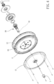
Fig. 4 is a partial breakdown drawing of a preferable embodiment of the present invention; -
Fig. 5 is a detailed breakdown drawing of a preferable embodiment of the present invention; -
Fig. 6 is a drawing showing a shaft, a frame and two end caps of a preferable embodiment of the present invention; -
Fig. 7 is a side view of the shaft and the frame combined according to a preferable embodiment of the present invention; and -
Fig. 8 is a drawing showing the shaft and the two end caps combined according to - Please refer to
Figs. 1 to 8 for a preferable embodiment of the present invention. An electric wheel hub of the present invention includes ashell 1, amotor assembly 2 and abattery unit 3. - The
motor assembly 2 includes astator 21, arotor 27 and ashaft 28, thestator 21 and therotor 27 are received in theshell 1 and relatively rotatable, and therotor 27 is connected and rotatable with theshell 1. Theshaft 28 defines anaxial direction 41 and acircumferential direction 42, theshaft 28 is movable in theaxial direction 41 and disposed through thestator 21, and theshaft 28 and thestator 21 are relatively non-rotatable in thecircumferential direction 42. Thebattery unit 3 is received in theshell 1 and electrically connected with themotor assembly 2. Theshaft 28 is detachably connected with thestator 21 so that the wheel hub can be quickly detached or installed without dismantling parts in themotor assembly 2, which is easy to uninstall/install and lowers the repairing cost. - Specifically, the electric wheel hub further includes a first bearing 63 and a second bearing 64, the
shell 1 includes abase 12 and acover 11, and thecover 11 is detachably covered to thebase 12. Thecover 11 includes a first throughhole 111, thebase 12 includes a second throughhole 121, the first bearing 63 is received in the first throughhole 111, the second bearing 64 is received in the second throughhole 121, and theshaft 28 is disposed through the first bearing 63 and the second bearing 64 and protrusive out beyond opposing sides of theshell 1. Since theshaft 28 is detachably connected to thestator 21, the first bearing 63 and the second bearing 64 do not have to be detached as theshaft 28 is removed, which avoids loss of the first bearing 63 and the second bearing 64, and simplifies the detachment process. To replace the first bearing 63 or the second bearing 64, themotor assembly 2 does not have to be detached, which is easy and convenient. - Specifically, the
shaft 28 further includes afirst end portion 51, aconnection portion 52, aflange 53 and asecond end portion 55 in sequence. Thefirst end portion 51 is disposed through the first bearing 63 and thecover 11, thesecond end portion 55 is disposed through thesecond bearing 64 and thebase 12, and theconnection portion 52 is connected with thestator 21. An intersection of theconnection portion 52 and thefirst end portion 51 includes astepped portion 521, the first bearing 63 is abutted against thecover 11 and thestepped portion 521 in theaxial direction 41, and the second bearing 64 is abutted between thebase 12 and theflange 53 between so as to improve stability of the first bearing 63 and the second bearing 64. - The
shaft 28 further includes anaxle 57 and a plurality of firstengaging portions 58, and the plurality of firstengaging portions 58 are separately arranged on theaxle 57 in thecircumferential direction 42. Theaxle 57 includes thefirst end portion 51, theconnection portion 52, theflange 53 and thesecond end portion 55, theconnection portion 52 includes the plurality of firstengaging portions 58, and thestator 21 includes aperforation 22 and a plurality of secondengaging portions 23. The plurality of secondengaging portions 23 are separately arranged around theperforation 22 in thecircumferential direction 42. Theaxle 57 is disposed through theperforation 22. The plurality of firstengaging portions 58 and the plurality of secondengaging portions 23 are engaged with each other so that theshaft 28 is detachable from thestator 21. One of each said first engagingportion 58 and the secondengaging portion 23 is a first groove, and the other of each said first engagingportion 58 and the secondengaging portion 23 is a first rib. For example, each said first engagingportion 58 is a first rib, and each said secondengaging portion 23 is a first groove. - Preferably, the
shaft 28 further includes a thirdengaging portion 59, thestator 21 further includes a fourthengaging portion 24, and the thirdengaging portion 59 and the fourthengaging portion 24 are engaged with each other. One of the thirdengaging portion 59 and the fourthengaging portion 24 is a second groove, and the other of the thirdengaging portion 59 and the fourthengaging portion 24 is a second rib, so that theshaft 28 and thestator 21 can be easily and accurately assembled. The second groove is not identical to the first groove, and the second rib is not identical to the first rib. - The
battery unit 3 includes acartridge 31 and a plurality ofbatteries 32, and the plurality ofbatteries 32 are positionally received within thecartridge 31 so that it is easy to install and maintain and is stable. In other embodiments, thebattery unit 3 may be provided without thecartridge 31. Thecartridge 31 is preferably made of plastic material (such as ABS-PC material) which is of good insulation. - In this embodiment, the
cartridge 31 is annular, thecartridge 31 is disposed around themotor assembly 2, and the plurality ofbatteries 32 are separately disposed around themotor assembly 2. Specifically, themotor assembly 2 is inserted to a central portion of thecartridge 31, and thecartridge 31 is connected with thestator 21 and is not connected with theshell 1, so that thecartridge 31 is non-rotatable for providing good stability of the plurality ofbatteries 32. - Specifically, the
stator 21 includes aframe 25 and a winding coil set 26, thewinding coil set 26 is wound around theframe 25, theshaft 28 is disposed through theframe 25, theframe 25 includes theperforation 22, the plurality of secondengaging portions 23 and the fourthengaging portion 24, and thecartridge 31 is connected with theframe 25. As a result, to replace thebattery unit 3, it needs only to withdraw theshaft 28 and open thecover 11, and thebattery unit 3 can be easily replaced without dismantling parts inside themotor assembly 2 and without dismantling the first bearing 63 and the second bearing 64. - Preferably, inner walls of the
cartridge 31 and theshell 1 define at least oneinsertion portion 34 therebetween, and the at least oneinsertion portion 34 is configured for easy detachment of thecartridge 31 from theshell 1. In this embodiment, the at least one insertion portion includes a plurality ofinsertion portions 34, an outer circumferential wall of thecartridge 31 includes a plurality ofopenings 33, the plurality ofbatteries 32 are partially exposed from theopening 33, and the plurality ofopenings 33 and the inner wall of theshell 1 form the plurality of theinsertion portion 34. The plurality ofbatteries 32 can be observed from the plurality ofopenings 33, which helps to evaluate conditions of the plurality ofbatteries 32. - The electric wheel hub further includes two
end caps 7 configured to be respectively connected to twofork arms 91, the twoend caps 7 are detachably disposed respectively around opposing ends of theshaft 28, and theshaft 28 is hollow and configured for aspindle 92 to be disposed therethrough. Theshaft 28 which is hollow can lower the weight and increase compatibility for thespindle 92. For example, various types of end caps can be used to receive various types of the spindles (having respective diameters of 9 mm, 12 mm and 15 mm, for example). - Preferably, each of the opposing ends of the
shaft 28 includes afirst positioning portion 56, each of the twoend caps 7 includes asecond positioning portion 71, and thesecond positioning portion 71 and thefirst positioning portion 56 are engaged with each other so as to provide stable and accurate combination of the twoend caps 7 and theshaft 28. One of thefirst positioning portion 56 and thesecond positioning portion 71 is a projection, and the other of thefirst positioning portion 56 and thesecond positioning portion 71 is a recess. - In this embodiment, each said third engaging
portion 59 is one said second rib, and each said fourth engagingportion 24 is one said second groove. In thecircumferential direction 42, the second rib has a length more than 2 times a length of the first rib, which further enhances the structural strength of the combination. - An
electronic control unit 8 is disposed on thebase 12, and theelectronic control unit 8 is positioned to thesecond end portion 55 and abutted against theflange 53. Theelectronic control unit 8 is movable with theshaft 28 in theaxial direction 41, so that theelectronic control unit 8 can be individually replaced without dismantling theshell 1. Theflange 53 includes apenetration hole 54 extending in theaxial direction 41, and thepenetration hole 54 is configured for arranged wires to electrically connect theelectronic control unit 8 outside theshell 1 and themotor assembly 2 inside theshell 1. A side of theflange 53 facing toward the second throughhole 121 includes a firstannular member 61, and a side of theflange 53 facing toward theelectronic control unit 8 includes a secondannular member 62. The firstannular member 61 prevents dust and/or mist form coming into theshell 1, and the secondannular member 62 improves stability of the combination of theelectronic control unit 8 and theshaft 28 and provides good buffering and shock-absorption. - In sum, in the design of the electric wheel hub, the maintenance and/or
replacement frequency and difficulty of different components are taken into account, which allows the maintenance and/or replacement to be carried out without dismantling the motor assembly. As a result, it can greatly simplify the difficulty of maintenance and/or replacement. - Although particular embodiments of the invention have been described in detail for purposes of illustration, various modifications and enhancements may be made without departing from the scope of the invention.
Claims (9)
- An electric wheel hub, including:a shell (1);a motor assembly (2), including a stator (21), a rotor (27) and a shaft (28), the stator (21) and the rotor (27) being received in the shell (1) and relatively rotatable, the rotor (27) being connected and rotatable with the shell (1), the shaft (28) defining an axial direction (41) and a circumferential direction (42), the shaft (28) being movable in the axial direction (41) and disposed through the stator (21), the shaft (28) and the stator (21) being relatively non-rotatable in the circumferential direction (42); anda battery unit (3), received in the shell (1), electrically connected with the motor assembly (2)characterized in thatthe electric wheel hub further includes two end caps (7) configured to be respectively connected to two fork arms (91), wherein the two end caps (7) are detachably disposed respectively around opposing ends of the shaft (28), and the shaft (28) is hollow and configured for a spindle (92) to be disposed therethrough.
- The electric wheel hub of claim 1, wherein the battery unit (3) includes a cartridge (31) and a plurality of batteries (32), and the plurality of batteries (32) are positionally received within the cartridge (31).
- The electric wheel hub of claim 2, wherein inner walls of the cartridge (31) and the shell (1) define at least one insertion portion (34) therebetween, and the at least one insertion portion (34) is configured for easy detachment of the cartridge (31) from the shell (1).
- The electric wheel hub of claim 2, wherein the cartridge (31) is disposed around the motor assembly (2), the cartridge (31) is connected with the stator (21) and is not connected with the shell (1), and the plurality of batteries (32) are disposed around the motor assembly (2) in intervals.
- The electric wheel hub of claim 1, further including a first bearing (63) and a second bearing (64), wherein the shell (1) includes a base (12) and a cover (11), the cover (11) is detachably covered to the base (12), the cover (11) includes a first through hole (111), the base (12) includes a second through hole (121), the first bearing (63) is received in the first through hole (111), the second bearing (64) is received in the second through hole (121), and the shaft (28) is disposed through the first bearing (63) and the second bearing (64) and protrusive out beyond opposing sides of the shell (1); the shaft (28) further includes a first end portion (51), a connection portion (52), a flange (53) and a second end portion (55) connected in sequence; the first end portion (51) is disposed through the first bearing (63) and the cover (11), the second end portion (55) is disposed through the second bearing (64) and the base (12), the connection portion (52) is connected with the stator (21), an intersection of the connection portion (52) and the first end portion (51) includes a stepped portion (521), the first bearing (63) is abutted against the cover (11) and the stepped portion (521) in the axial direction (41), and the second bearing (64) is abutted between the base (12) and the flange (53).
- The electric wheel hub of claim 1, wherein the shaft (28) further includes an axle (57) and a plurality of first engaging portions (58), the plurality of first engaging portions (58) are separately arranged on the axle (57) in the circumferential direction (42), the stator (21) includes a perforation (22) and a plurality of second engaging portions (23), the plurality of second engaging portions (23) are separately arranged around the perforation (22) in the circumferential direction (42), the axle (57) is disposed through the perforation (22), the plurality of first engaging portions (58) and the plurality of second engaging portions (23) are engaged with each other, one of each said first engaging portion (58) and each said second engaging portion (23) is a first groove, and the other of each said first engaging portion (58) and each said second engaging portion (23) is a first rib.
- The electric wheel hub of claim 6, wherein the shaft (28) further includes a third engaging portion (59), the stator (21) further includes a fourth engaging portion (24), the third engaging portion (59) and the fourth engaging portion (24) are engaged with each other, one of the third engaging portion (59) and the fourth engaging portion (24) is a second groove, and the other of the third engaging portion (59) and the fourth engaging portion (24) is a second rib; the second groove is not identical to the first groove, and the second rib is not identical to the first rib.
- The electric wheel hub of claim 1, wherein each of the opposing ends of the shaft (28) includes a first positioning portion (56), each of the two end caps (7) includes a second positioning portion (71), and the second positioning portion (71) and the first positioning portion (56) are engaged with each other; one of the first positioning portion (56) and the second positioning portion (71) is a projection, and the other of the first positioning portion (56) and the second positioning portion (71) is a recess.
- The electric wheel hub of claim 7, wherein the battery unit (3) includes a cartridge (31) and a plurality of batteries (32), and the plurality of batteries (32) are positionally received within the cartridge (31); inner walls of the cartridge (31) and the shell (1) define at least one insertion portion (34) therebetween, and the at least one insertion portion (34) is configured for easy detachment of the cartridge (31) from the shell (1); the cartridge (31) is disposed around the motor assembly (2), the cartridge (31) is connected with the stator (21) and is not connected with the shell (1), and the plurality of batteries (32) are disposed around the motor assembly (2) in intervals; the electric wheel hub further includes a first bearing (63) and a second bearing (64), the shell (1) includes a base (12) and a cover (11), the cover (11) is detachably covered to the base (12), the cover (11) includes a first through hole (111), the base (12) includes a second through hole (121), the first bearing (63) is received in the first through hole (111), the second bearing (64) is received in the second through hole (121), the shaft (28) is disposed through the first bearing (63) and the second bearing (64) and protrusive out beyond opposing sides of the shell (1); the shaft (28) further includes a first end portion (51), a connection portion (52), a flange (53) and a second end portion (55) connected in sequence; the first end portion (51) is disposed through the first bearing (63) and the cover (11), the second end portion (55) is disposed through the second bearing (64) and the base (12), the connection portion (52) is connected with the stator (21), an intersection of the connection portion (52) and the first end portion (51) includes a stepped portion (521), the first bearing (63) is abutted against the cover (11) and the stepped portion (521) in the axial direction (41), and the second bearing (64) is abutted between the base (12) and the flange (53); the electric wheel hub further includes two end caps (7) configured to be respectively connected to two fork arms (91), the two end caps (7) are detachably disposed around opposing ends of the shaft (28), and the shaft (28) is hollow and configured for a spindle (92) to be disposed therethrough; each of the opposing ends of the shaft (28) includes a first positioning portion (56), each of the two end caps (7) includes a second positioning portion (71), and the second positioning portion (71) and the first positioning portion (56) are engaged with each other; one of the first positioning portion (56) and the second positioning portion (71) is a projection, and the other of the first positioning portion (56) and the second positioning portion (71) is a recess; the cartridge (31) is made of plastic material; the cartridge (31) is annular, the motor assembly (2) is inserted to a central portion of the cartridge (31); the at least one insertion portion (34) includes a plurality of insertion portions (34), and an outer circumferential wall of the cartridge (31) includes a plurality of openings (33), the plurality of batteries (32) are partially exposed from the plurality of openings (33); an electronic control unit (8) is disposed on the base (12), and the electronic control unit (8) is positioned to the second end portion (55) and abutted against the flange (53); the flange (53) includes a penetration hole (54) extending in the axial direction (41); a side of the flange (53) facing toward the second through hole (121) includes a first annular member (61), and a side of the flange (53) facing toward the electronic control unit (8) includes a second annular member (62); each said first engaging portion (58) is one said first rib, each said second engaging portion (23)is one said first groove, each said third engaging portion (59) is one said second rib, each said fourth engaging portion (24) is one said second groove; in the circumferential direction (42), the second rib has a length more than 2 times a length of the first rib; the axle (57) includes the first end portion (51), the connection portion (52), the flange (53) and the second end portion (55), and the connection portion (52) includes the plurality of first engaging portions (58); the stator (21) includes a frame (25) and a winding coil set (26), the winding coil set (26) is wound around the frame (25), and the shaft (28) is disposed through the frame (25); the frame (25) includes the perforation (22), the plurality of second engaging portions (23) and the fourth engaging portion (24), and the cartridge (31) is connected with the frame (25).
Applications Claiming Priority (1)
| Application Number | Priority Date | Filing Date | Title |
|---|---|---|---|
| TW109146493A TWI760032B (en) | 2020-12-28 | 2020-12-28 | Electric wheel hub |
Publications (3)
| Publication Number | Publication Date |
|---|---|
| EP4019308A1 EP4019308A1 (en) | 2022-06-29 |
| EP4019308B1 true EP4019308B1 (en) | 2025-05-14 |
| EP4019308C0 EP4019308C0 (en) | 2025-05-14 |
Family
ID=78332558
Family Applications (1)
| Application Number | Title | Priority Date | Filing Date |
|---|---|---|---|
| EP21203570.3A Active EP4019308B1 (en) | 2020-12-28 | 2021-10-19 | Electric wheel hub |
Country Status (4)
| Country | Link |
|---|---|
| US (1) | US20220204133A1 (en) |
| EP (1) | EP4019308B1 (en) |
| CN (1) | CN114074742A (en) |
| TW (1) | TWI760032B (en) |
Families Citing this family (1)
| Publication number | Priority date | Publication date | Assignee | Title |
|---|---|---|---|---|
| NO346537B1 (en) * | 2021-02-11 | 2022-09-26 | Punda As | Wheel assembly for a unitractor and a unitractor comprising said wheel assembly |
Family Cites Families (30)
| Publication number | Priority date | Publication date | Assignee | Title |
|---|---|---|---|---|
| US5272938A (en) * | 1992-12-04 | 1993-12-28 | Hsu Chi Hsueh | Flat rim type motor drive mechanism for bicycles |
| US6787951B2 (en) * | 2001-10-01 | 2004-09-07 | Wavecrest Laboratories, Llc | Rotary electric motor having controller and power supply integrated therein |
| US6617746B1 (en) * | 2001-10-01 | 2003-09-09 | Wavecrest Laboratories, Llc | Rotary electric motor having axially aligned stator poles and/or rotor poles |
| CA2793287A1 (en) * | 2010-03-17 | 2011-09-22 | Propulsion Powercycle Inc. | Bicycle with electrical drive system |
| US20110259658A1 (en) * | 2010-04-22 | 2011-10-27 | Lin Hsiang Huang | Power output device for wheeled vehicle |
| JP5149938B2 (en) * | 2010-06-11 | 2013-02-20 | 株式会社シマノ | Bicycle hub with built-in motor |
| US8419581B2 (en) * | 2010-10-01 | 2013-04-16 | Chiu-Hsiang Lo | Hub motor for electric vehicles |
| US8419580B2 (en) * | 2010-10-01 | 2013-04-16 | Chiu-Hsiang Lo | Electric wheel for electric vehicles |
| DE102010062534A1 (en) * | 2010-12-07 | 2012-06-14 | Robert Bosch Gmbh | Electromotive drive device, in particular for a two-wheeler |
| ITMO20110060A1 (en) * | 2011-03-16 | 2012-09-17 | C R D Ct Ricerche Ducati Trent O S R L | WHEEL FOR ASSISTED RIDING BICYCLES |
| TWM421293U (en) * | 2011-07-11 | 2012-01-21 | Fairly Bike Mfg Co Ltd | Assembling structure for bicycle frame and electric hub |
| CN104755367B (en) * | 2012-12-05 | 2018-01-09 | 松下知识产权经营株式会社 | It is electronic to use hub unit and electric bicycle |
| ITMO20130111A1 (en) * | 2013-04-23 | 2014-10-24 | C R D Ct Ricerche Ducati Trent O S R L | WHEEL FOR ASSISTED RIDING BICYCLES |
| AT516540B1 (en) * | 2014-12-03 | 2016-09-15 | Babeluk Michael | RETROFITTING AND RETROFITTING A TWO-WHEEL |
| EP3233619B1 (en) * | 2014-12-17 | 2022-02-23 | Williams Advanced Engineering Limited | An electric drive wheel hub assembly for an electrically assisted vehicle and a vehicle incorporating the same |
| US9802673B2 (en) * | 2015-05-18 | 2017-10-31 | GM Global Technology Operations LLC | Electric bike powertrain with dual planetary gear sets and ring gear pedal reaction torque measurement |
| KR101685599B1 (en) * | 2016-07-08 | 2016-12-13 | 주식회사 에이치엔이 | The Electric bicycle battery-powered drive unit |
| US11091023B2 (en) * | 2016-07-29 | 2021-08-17 | Ford Global Technologies, Llc | Wheel assembly |
| CN107466279A (en) * | 2016-08-29 | 2017-12-12 | 深圳哥智行科技有限公司 | A kind of wheel hub of electric bicycle |
| TWI656043B (en) * | 2017-11-08 | 2019-04-11 | 財團法人工業技術研究院 | Electric wheel |
| TWI701176B (en) * | 2017-12-01 | 2020-08-11 | 英屬開曼群島商睿能創意公司 | Hub apparatus and wheel |
| TWM580517U (en) * | 2019-01-28 | 2019-07-11 | 太宇工業股份有限公司 | Replaceable hub system wheel set and bicycle having replaceable hub system wheel set |
| TWM580522U (en) | 2019-01-30 | 2019-07-11 | 莊浩于 | Dual power driven wheel hub |
| CN113474246B (en) * | 2019-02-28 | 2022-07-08 | 阿莫泰克有限公司 | Hub type driving device and electric bicycle using same |
| WO2021096143A1 (en) * | 2019-11-13 | 2021-05-20 | 주식회사 아모텍 | Hub-type electric driving device |
| KR102371546B1 (en) * | 2019-11-13 | 2022-03-08 | 주식회사 아모텍 | Electrically-driven Apparatus of Hub Type |
| TWM599256U (en) * | 2020-05-14 | 2020-08-01 | 黃志忠 | Anti-slip hollow shaft structure of bicycle hub and bicycle hub |
| TWI757014B (en) * | 2020-12-28 | 2022-03-01 | 秀育企業股份有限公司 | Electric wheel hub composite structure and disassembly method of the same |
| ES2998044T3 (en) * | 2021-09-16 | 2025-02-18 | Mahle Int Gmbh | Motor device for an electric bicycle |
| TWM625262U (en) * | 2021-12-15 | 2022-04-01 | 百鑽精研國際股份有限公司 | In-wheel motors and electric bicycle drives |
-
2020
- 2020-12-28 TW TW109146493A patent/TWI760032B/en active
-
2021
- 2021-09-27 CN CN202111133539.0A patent/CN114074742A/en active Pending
- 2021-10-12 US US17/499,321 patent/US20220204133A1/en not_active Abandoned
- 2021-10-19 EP EP21203570.3A patent/EP4019308B1/en active Active
Also Published As
| Publication number | Publication date |
|---|---|
| CN114074742A (en) | 2022-02-22 |
| TW202225021A (en) | 2022-07-01 |
| TWI760032B (en) | 2022-04-01 |
| US20220204133A1 (en) | 2022-06-30 |
| EP4019308C0 (en) | 2025-05-14 |
| EP4019308A1 (en) | 2022-06-29 |
Similar Documents
| Publication | Publication Date | Title |
|---|---|---|
| EP4019309B1 (en) | Electric wheel hub and method of disassembling the same | |
| US6225725B1 (en) | Manufacturing process of a divided type stator | |
| EP1536543B1 (en) | Rotor for external rotor-type permanent magnet motor | |
| EP4019308B1 (en) | Electric wheel hub | |
| JP2003034279A (en) | Bicycle hub shaft with dynamo | |
| CN202840784U (en) | Motor | |
| CN105391238A (en) | Geared motor and damper device | |
| JP6121115B2 (en) | Commutator | |
| US20240006941A1 (en) | Rotor and rotary electric machine | |
| JPH06311675A (en) | Split annular core | |
| KR101837863B1 (en) | Traction motor module and motor electricity bicycle | |
| CN109412297B (en) | Balanced-ring-free embedded servo motor rotor assembly and manufacturing method | |
| EP0552378A1 (en) | Stator/housing assembly of an electric motor | |
| KR20210023555A (en) | Assembly structure of resolver assembly for drive motor | |
| CN203522401U (en) | Motor | |
| KR101685202B1 (en) | Traction motor module and motor electricity bicycle | |
| CN212258550U (en) | Electric generator | |
| JP2023175187A (en) | Electric vehicle motor | |
| CN216146180U (en) | PM stepping motor concentric assembly structure | |
| CN209503325U (en) | Piece stator pack justifies welding tooling | |
| CN203301319U (en) | Rotation motor | |
| CN223702167U (en) | A hub housing for electric bicycles | |
| JP4372130B2 (en) | motor | |
| JP2005027384A (en) | Bracket in rotary electric machine | |
| CN113206555B (en) | Stator assembly, motor and electromechanical device |
Legal Events
| Date | Code | Title | Description |
|---|---|---|---|
| PUAI | Public reference made under article 153(3) epc to a published international application that has entered the european phase |
Free format text: ORIGINAL CODE: 0009012 |
|
| STAA | Information on the status of an ep patent application or granted ep patent |
Free format text: STATUS: THE APPLICATION HAS BEEN PUBLISHED |
|
| AK | Designated contracting states |
Kind code of ref document: A1 Designated state(s): AL AT BE BG CH CY CZ DE DK EE ES FI FR GB GR HR HU IE IS IT LI LT LU LV MC MK MT NL NO PL PT RO RS SE SI SK SM TR |
|
| STAA | Information on the status of an ep patent application or granted ep patent |
Free format text: STATUS: REQUEST FOR EXAMINATION WAS MADE |
|
| 17P | Request for examination filed |
Effective date: 20220729 |
|
| RBV | Designated contracting states (corrected) |
Designated state(s): AL AT BE BG CH CY CZ DE DK EE ES FI FR GB GR HR HU IE IS IT LI LT LU LV MC MK MT NL NO PL PT RO RS SE SI SK SM TR |
|
| STAA | Information on the status of an ep patent application or granted ep patent |
Free format text: STATUS: EXAMINATION IS IN PROGRESS |
|
| 17Q | First examination report despatched |
Effective date: 20241010 |
|
| GRAP | Despatch of communication of intention to grant a patent |
Free format text: ORIGINAL CODE: EPIDOSNIGR1 |
|
| STAA | Information on the status of an ep patent application or granted ep patent |
Free format text: STATUS: GRANT OF PATENT IS INTENDED |
|
| INTG | Intention to grant announced |
Effective date: 20250217 |
|
| GRAS | Grant fee paid |
Free format text: ORIGINAL CODE: EPIDOSNIGR3 |
|
| GRAA | (expected) grant |
Free format text: ORIGINAL CODE: 0009210 |
|
| STAA | Information on the status of an ep patent application or granted ep patent |
Free format text: STATUS: THE PATENT HAS BEEN GRANTED |
|
| AK | Designated contracting states |
Kind code of ref document: B1 Designated state(s): AL AT BE BG CH CY CZ DE DK EE ES FI FR GB GR HR HU IE IS IT LI LT LU LV MC MK MT NL NO PL PT RO RS SE SI SK SM TR |
|
| REG | Reference to a national code |
Ref country code: GB Ref legal event code: FG4D |
|
| REG | Reference to a national code |
Ref country code: CH Ref legal event code: EP |
|
| REG | Reference to a national code |
Ref country code: IE Ref legal event code: FG4D |
|
| U01 | Request for unitary effect filed |
Effective date: 20250515 |
|
| U07 | Unitary effect registered |
Designated state(s): AT BE BG DE DK EE FI FR IT LT LU LV MT NL PT RO SE SI Effective date: 20250521 |
|
| PG25 | Lapsed in a contracting state [announced via postgrant information from national office to epo] |
Ref country code: ES Free format text: LAPSE BECAUSE OF FAILURE TO SUBMIT A TRANSLATION OF THE DESCRIPTION OR TO PAY THE FEE WITHIN THE PRESCRIBED TIME-LIMIT Effective date: 20250514 |
|
| PG25 | Lapsed in a contracting state [announced via postgrant information from national office to epo] |
Ref country code: GR Free format text: LAPSE BECAUSE OF FAILURE TO SUBMIT A TRANSLATION OF THE DESCRIPTION OR TO PAY THE FEE WITHIN THE PRESCRIBED TIME-LIMIT Effective date: 20250815 Ref country code: NO Free format text: LAPSE BECAUSE OF FAILURE TO SUBMIT A TRANSLATION OF THE DESCRIPTION OR TO PAY THE FEE WITHIN THE PRESCRIBED TIME-LIMIT Effective date: 20250814 |
|
| PG25 | Lapsed in a contracting state [announced via postgrant information from national office to epo] |
Ref country code: PL Free format text: LAPSE BECAUSE OF FAILURE TO SUBMIT A TRANSLATION OF THE DESCRIPTION OR TO PAY THE FEE WITHIN THE PRESCRIBED TIME-LIMIT Effective date: 20250514 |
|
| PG25 | Lapsed in a contracting state [announced via postgrant information from national office to epo] |
Ref country code: HR Free format text: LAPSE BECAUSE OF FAILURE TO SUBMIT A TRANSLATION OF THE DESCRIPTION OR TO PAY THE FEE WITHIN THE PRESCRIBED TIME-LIMIT Effective date: 20250514 |
|
| PG25 | Lapsed in a contracting state [announced via postgrant information from national office to epo] |
Ref country code: RS Free format text: LAPSE BECAUSE OF FAILURE TO SUBMIT A TRANSLATION OF THE DESCRIPTION OR TO PAY THE FEE WITHIN THE PRESCRIBED TIME-LIMIT Effective date: 20250814 |
|
| U20 | Renewal fee for the european patent with unitary effect paid |
Year of fee payment: 5 Effective date: 20250915 |
|
| PG25 | Lapsed in a contracting state [announced via postgrant information from national office to epo] |
Ref country code: IS Free format text: LAPSE BECAUSE OF FAILURE TO SUBMIT A TRANSLATION OF THE DESCRIPTION OR TO PAY THE FEE WITHIN THE PRESCRIBED TIME-LIMIT Effective date: 20250914 |
|
| PG25 | Lapsed in a contracting state [announced via postgrant information from national office to epo] |
Ref country code: SM Free format text: LAPSE BECAUSE OF FAILURE TO SUBMIT A TRANSLATION OF THE DESCRIPTION OR TO PAY THE FEE WITHIN THE PRESCRIBED TIME-LIMIT Effective date: 20250514 |
|
| PG25 | Lapsed in a contracting state [announced via postgrant information from national office to epo] |
Ref country code: CZ Free format text: LAPSE BECAUSE OF FAILURE TO SUBMIT A TRANSLATION OF THE DESCRIPTION OR TO PAY THE FEE WITHIN THE PRESCRIBED TIME-LIMIT Effective date: 20250514 |
|
| PG25 | Lapsed in a contracting state [announced via postgrant information from national office to epo] |
Ref country code: SK Free format text: LAPSE BECAUSE OF FAILURE TO SUBMIT A TRANSLATION OF THE DESCRIPTION OR TO PAY THE FEE WITHIN THE PRESCRIBED TIME-LIMIT Effective date: 20250514 |
|
| PLBE | No opposition filed within time limit |
Free format text: ORIGINAL CODE: 0009261 |
|
| STAA | Information on the status of an ep patent application or granted ep patent |
Free format text: STATUS: NO OPPOSITION FILED WITHIN TIME LIMIT |
|
| REG | Reference to a national code |
Ref country code: CH Ref legal event code: L10 Free format text: ST27 STATUS EVENT CODE: U-0-0-L10-L00 (AS PROVIDED BY THE NATIONAL OFFICE) Effective date: 20260325 |
|
| 26N | No opposition filed |
Effective date: 20260217 |