EP4019293A2 - Tire - Google Patents
Tire Download PDFInfo
- Publication number
- EP4019293A2 EP4019293A2 EP21215883.6A EP21215883A EP4019293A2 EP 4019293 A2 EP4019293 A2 EP 4019293A2 EP 21215883 A EP21215883 A EP 21215883A EP 4019293 A2 EP4019293 A2 EP 4019293A2
- Authority
- EP
- European Patent Office
- Prior art keywords
- tire
- flipper
- rfid tag
- bead
- radial direction
- Prior art date
- Legal status (The legal status is an assumption and is not a legal conclusion. Google has not performed a legal analysis and makes no representation as to the accuracy of the status listed.)
- Granted
Links
Images



Classifications
-
- B—PERFORMING OPERATIONS; TRANSPORTING
- B60—VEHICLES IN GENERAL
- B60C—VEHICLE TYRES; TYRE INFLATION; TYRE CHANGING; CONNECTING VALVES TO INFLATABLE ELASTIC BODIES IN GENERAL; DEVICES OR ARRANGEMENTS RELATED TO TYRES
- B60C15/00—Tyre beads, e.g. ply turn-up or overlap
- B60C15/06—Flipper strips, fillers, or chafing strips and reinforcing layers for the construction of the bead
- B60C15/0628—Flipper strips, fillers, or chafing strips and reinforcing layers for the construction of the bead comprising a bead reinforcing layer
- B60C15/0632—Flipper strips, fillers, or chafing strips and reinforcing layers for the construction of the bead comprising a bead reinforcing layer using flippers in contact with and wrapped around the bead core and, at least partially, in contact with the bead filler
-
- B—PERFORMING OPERATIONS; TRANSPORTING
- B60—VEHICLES IN GENERAL
- B60C—VEHICLE TYRES; TYRE INFLATION; TYRE CHANGING; CONNECTING VALVES TO INFLATABLE ELASTIC BODIES IN GENERAL; DEVICES OR ARRANGEMENTS RELATED TO TYRES
- B60C19/00—Tyre parts or constructions not otherwise provided for
-
- G—PHYSICS
- G06—COMPUTING OR CALCULATING; COUNTING
- G06K—GRAPHICAL DATA READING; PRESENTATION OF DATA; RECORD CARRIERS; HANDLING RECORD CARRIERS
- G06K19/00—Record carriers for use with machines and with at least a part designed to carry digital markings
- G06K19/06—Record carriers for use with machines and with at least a part designed to carry digital markings characterised by the kind of the digital marking, e.g. shape, nature, code
- G06K19/067—Record carriers with conductive marks, printed circuits or semiconductor circuit elements, e.g. credit or identity cards also with resonating or responding marks without active components
- G06K19/07—Record carriers with conductive marks, printed circuits or semiconductor circuit elements, e.g. credit or identity cards also with resonating or responding marks without active components with integrated circuit chips
- G06K19/077—Constructional details, e.g. mounting of circuits in the carrier
- G06K19/0772—Physical layout of the record carrier
-
- G—PHYSICS
- G06—COMPUTING OR CALCULATING; COUNTING
- G06K—GRAPHICAL DATA READING; PRESENTATION OF DATA; RECORD CARRIERS; HANDLING RECORD CARRIERS
- G06K7/00—Methods or arrangements for sensing record carriers, e.g. for reading patterns
- G06K7/10—Methods or arrangements for sensing record carriers, e.g. for reading patterns by electromagnetic radiation, e.g. optical sensing; by corpuscular radiation
- G06K7/10009—Methods or arrangements for sensing record carriers, e.g. for reading patterns by electromagnetic radiation, e.g. optical sensing; by corpuscular radiation sensing by radiation using wavelengths larger than 0.1 mm, e.g. radio-waves or microwaves
-
- B—PERFORMING OPERATIONS; TRANSPORTING
- B60—VEHICLES IN GENERAL
- B60C—VEHICLE TYRES; TYRE INFLATION; TYRE CHANGING; CONNECTING VALVES TO INFLATABLE ELASTIC BODIES IN GENERAL; DEVICES OR ARRANGEMENTS RELATED TO TYRES
- B60C19/00—Tyre parts or constructions not otherwise provided for
- B60C2019/004—Tyre sensors other than for detecting tyre pressure
Definitions
- the present invention relates to a tire in which an electronic component is embedded.
- Patent Document 1 discloses a tire embedding an RF tag in the vicinity of a stiffener.
- Patent Document 1 Japanese Unexamined Patent Application, Publication No. 2016-37236
- Patent Document 1 According to the technology illustrated in Patent Document 1, it is possible to carry out production management, shipping management, usage history management, etc. of tires.
- the RF tag is arranged between the stiffener and side rubber, and a fiber layer such as a carcass ply does not exist between the RF tag and tire outer wall. Consequently, there is concern over the RF tag not being protected and becoming damaged in a case of the tire greatly distorting or a case of shock acting on the tire.
- the present invention has been made taking account of the above-mentioned problem, and an object thereof is to provide a tire which can protect an electronic component.
- a tire according to the present invention includes: a pair of beads having a bead core and a bead filler which extends to an outer side in a tire-radial direction of the bead core; a flipper which envelops at least part of the bead; a carcass ply which has a ply body extending from one bead to another bead, and a ply folding part which is folded back at the bead, and which envelopes the flipper; and an RFID tag as an electronic component embedded within the tire so as to make contact with the flipper.
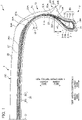
- FIG. 1 is a view showing a half section in a tire-width direction of a tire 1 according to the present embodiment.
- the basic structure of the tire 1 is left/right symmetric in the cross section of the tire-width direction; therefore, a cross-sectional view of the right half is shown herein.
- the reference symbol S1 is the tire equatorial plane.
- the tire equatorial plane S1 is a plane orthogonal to the tire rotation axis (tire meridian), and is positioned in the center of the tire-width direction.
- tire-width direction is a direction parallel to the tire rotation axis, and is the left/right direction of the paper plane of the cross-sectional view in FIG. 1 .
- it is illustrated as the tire-width direction X.
- inner side of tire-width direction is a direction approaching the tire equatorial plane S1, and is the left side of the paper plane in FIG. 1 .
- Outer side of tire-width direction is a direction distancing from the tire equatorial plane S1, and is the right side of the paper plane in FIG. 1 .
- tire-radial direction is a direction perpendicular to the tire rotation axis, and is the vertical direction in the paper plane of FIG. 1 .
- FIG. 1 it is illustrated as the tire-width direction X.
- inner side of tire-width direction is a direction approaching the tire equatorial plane S1, and is the left side of the paper plane in FIG. 1 .
- Outer side of tire-width direction is a direction dis
- tire-radial direction Y it is illustrated as the tire-radial direction Y.
- outer side of tire-radial direction is a direction distancing from the tire rotation axis, and is the upper side of the paper plane in FIG. 1 .
- Inner side of tire-radial direction is a direction approaching the tire rotation axis, and is the lower side of the paper plane in FIG. 1 .
- the cross-sectional view of FIG. 1 is a tire-width direction cross-sectional view (tire meridian axis cross-sectional view) in a state mounting the tire to a standard rim, and filling the standard internal pressure.
- standard rim indicates a rim serving as a standard decided by JATMA to correspond to the tire size.
- standard internal pressure is 180 kPa in the case of the tire being for a passenger vehicle, for example.
- the tire 1 is a tire for passenger cars, for example, and includes a pair of beads 11 provided at both sides in the tire-width direction, a sidewall 12 which extends from each of the beads 11 to the outer side in the tire-radial direction; and annular tread 13 which connects to the outer side in the tire-radial direction of each of the sidewalls 12 and extends in the circumferential direction of the tire constituting the tire tread (contact patch with road surface R) 13C.
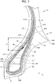
- FIG. 2 shows an enlarged cross-sectional view in the periphery in a tire-radial direction inside region of the bead 11 and sidewall 12 of the tire 1 of the present embodiment shown in FIG. 1 .
- the bead 11 includes a bead core 21, and bead filler 22 extending to the outer side in the tire-radial direction of the bead core 21.
- the bead core 21 is an annular member formed by wrapping around several times bead wires made of metal coated with rubber, and is a member which plays a role of fixing the tire 1 filled with air to the rim (not shown) of a wheel.
- the bead filler 22 is a rubber member of tapered tip shape, extending to the outer side in the tire-radial direction of the bead core 21.
- the bead filler 22 has a tire-radial direction outside end 22A and a tire-radial direction inside end 22B.
- the tire-radial direction inside end 22B of the bead filler 22 contacts with the tire-radial direction outside end 21A of the bead core 21.
- the bead filler 22 is a member provided in order to raise the rigidity of the bead peripheral part and to ensure high maneuverability and stability.
- the bead filler 22 is configured by rubber of higher hardness than the surrounding rubber members, for example.
- the modulus of rubber constituting the bead filler is higher than at least the modulus of rubber constituting the inner liner 29 described later and the rubber constituting the sidewall 30.
- a carcass ply 23 bridging between the pair of beads 11 is embedded inside of the tire 1.
- the carcass ply 23 configures a ply serving as the backbone of the tire 1, and is embedded within the tire 1, in a form passing through the pair of sidewalls 12 and the tread 13 between the pair of beads 11.
- the carcass ply 23 includes the ply body 24 which extends from one bead core 21 to the other bead core 21 and exists between the tread 13 and bead 11; and the ply folding part 25 which is folded back around the bead core 21.
- the ply folding part 25 is overlapped with the ply body 24 in the region of the sidewall 12.
- a ply folding part 25 has an end 25A.
- the end 25A of the ply folding part 25 is positioned in a region of the sidewall 12.
- the carcass ply 23 is configured by a plurality of ply cords extending in the tire-width direction.
- a plurality of ply cords is arranged side by side in a tire circumferential direction.
- This ply cord is configured by an insulated organic fiber cord such as polyester or polyamide, or the like, and is covered by topping rubber.
- the ply coating constituting the carcass ply 23 is arranged radially (radial direction) from the center of the tire 1.
- the tire 1 of the present embodiment is a so-called radial tire in which ply cords are arranged so as to extend radially.
- the carcass ply 23 of the present embodiment is a single-layer structure carcass ply 23 including one layer of a ply body 24.
- the carcass ply 23 may be a multi-layer structure carcass ply 23 including a plurality of layers of ply body 24.
- the bead 11 further includes a chamfer 31, and rim strip rubber 32 arranged at the tire-width direction outer side of the chamfer 31.
- the chafer 31 is provided so as to cover the carcass ply 23 provided around the bead core 21.
- the chafer 31 is provided so as to cover the inner side in the tire-width direction, inner side in the tire-radial direction and outer side in the tire-width direction of the carcass ply 23 at the periphery of the bead core 21.
- the chafer 31 has a first end 31A arranged on the inner side in the tire-width direction of the ply body 24, and a second end 31B arranged at the outer side in the tire-width direction of the ply folding part 25 of the carcass ply 23.
- the chafer 31 is configured from rubber into which fibers were kneaded, or rubber of high modulus, for example, and the relative strength is high among constituent members constituting the tire 1. For example, the strength is higher than the inner liner 29 and side-wall rubber 30 described later.
- the rim strip rubber 32 is a rubber member arranged on the outer side in the tire-width direction of the chafer 31 and the ply folding part 25 of the carcass ply 23, and upon the tire 1 being mounted to a wheel, the outer side in the tire-width direction thereof makes contact with the rim (not shown) of the wheel.
- the rim strip rubber 32 has a tire-radial direction outside end 32A and tire-radial direction inside end 32B. The outer side in the tire-radial direction of this rim strip rubber 32 connects to the side-wall rubber 30.
- the flipper 50 is arranged at the bead 11.
- the flipper 50 is a reinforced fiber layer provided so as to cover the bead core 21.
- the flipper 50 raises the rigidity of the bead overall.
- the pressure bonding property between the bead 11 and rid is high, which can thereby suppress rim deviation of the bead 11.
- the flipper 50 is arranged to as to be sandwiched between the bead core 21 and carcass ply 23 provided around the bead core 21.
- the flipper 50 includes a first portion 51 cover the inner side in the tire-width direction of the bead core 21, second portion 52 covering the inner side in the tire-radial direction, and third portion covering the outer side in the tire-width direction.
- the flipper 50 envelops at least part of the bead 11.
- the flipper 50 envelops at least part of the bead core 21 constituting the bead 11, by the first portion 51, second portion 52 and third portion 53.
- the flipper 50 envelops the bead core 21 constituting the bead 11, and the bead filler 22.
- the first portion 51 extends more to the outer side in the tire-radial direction than the bead core 21.
- a tire-radial direction outside end 51A of the first portion 51 is arranged more to the outer side in the tire-radial direction than the tire-radial direction outside end 22A of the bead filler 22.
- the first portion 51 is arranged so as to cover the inner side in the tire-width direction of the bead filler 22, in addition to the inner side in the tire-width direction of the bead core 21.
- the first portion 51 has a portion arranged to be sandwiched between the inner side in the tire-width direction of the bead core 21 and the ply body 24, and a portion arranged to be sandwiched between the inner side in the tire-width direction of the bead filler 22 and the ply body 24.
- the first portion 51 further includes: a portion arranged to be sandwiched between the ply body 24 and the third portion 53 of the flipper 50, and a portion arranged to be sandwiched between the ply body 24 and the ply folding part 25.
- the tire-radial direction outside end 51A of the first portion 51 is arranged at a tire-radial direction position of the sidewall 12 corresponding to a portion at which the tire inner cavity part is the widest in the tire-width direction.
- the tire-radial direction outside end 51A of the first portion 51 is preferably arranged at the tire-radial direction portion corresponding to a portion at which the tire inner cavity part is the widest in the tire-width direction, or more to the inner side in the tire-radial direction than this.
- the tire-radial direction outside end 51A of the first portion 51 may be arranged at a tire-radial direction position similarly to the tire-radial direction outside end 22A of the bead filler 22, or more to the inner side in the tire-radial direction than this. It is sufficient so long as the flipper 50 envelops at least part of the bead 11.
- the tire-radial direction position of the tire-radial direction outside end 51A of the first portion 51 is adjusted according to the rigidity demanded in the tire 1.
- the second portion 52 is arranged to be sandwiched between the inner side in the tire-radial direction of the bead core 21 and the carcass ply 23.
- the third portion 53 extends more to the outer side in the tire-radial direction than the bead core 21.
- the tire-radial direction outside end 53A of the third portion 53 is arranged more to the outer side in the tire-radial direction than the tire-radial direction outside end 22A of the bead filler 22.
- the third portion 53 is arranged so as to cover the outer side in the tire-width direction of the bead filler 22, in addition to the outer side in the tire-width direction of the bead core 21.
- the third portion 53 has a portion arranged to be sandwiched between the outer side in the tire-width direction of the bead core 21 and the ply folding part 25, and a portion arranged to be sandwiched between the outer side in the tire-width direction of the bead filler 22 and the ply folding part 25.
- the third portion 53 further has a portion arranged to be sandwiched between the ply folding part 25 and the first portion 51 of the flipper 50.
- the tire-radial direction outside end 53A of the third portion 53 is arranged more to the inner side in the tire-radial direction than the tire-radial direction position of the sidewall 12 corresponding to the portion at which the tire inner cavity part is widest in the tire-width direction.
- the tire-radial direction outside end 53A of the third portion 53 is preferably arranged at a tire-radial direction position corresponding to a portion at which the tire inner cavity part is widest in the tire-width direction, or more to the inner side in the tire-radial direction than this.
- the tire-radial direction outside end 53A of the third portion 53 may be arranged at a tire-radial direction position similarly to the tire-radial direction outside end 22A of the bead filler 22, or more to the inner side in the tire-radial direction than this. It is sufficient so long as the flipper 50 envelops at least part of the bead 11.
- the tire-radial direction position of the tire-radial direction outside end 53A of the third portion 53 is adjusted according to the rigidity demanded in the tire 1.
- the tire-radial direction outside end 51A of the first portion 51 is positioned more to the outer side in the tire-radial direction than the tire-radial direction outside end 53A of the third portion 53. Therefore, the tire-radial direction outside end 51A of the first portion 51 constitutes the tire-radial direction outside end of the flipper 50. It should be noted that the tire-radial direction outside end 53A of the third portion 53 may be located more to the outer side in the tire-radial direction than the tire-radial direction outside end 51A of the first portion 51. In this case, the tire-radial direction outside end 53A of the third portion 53 constitutes the tire-radial direction outside end of the flipper 50.
- the flipper 50 of the present embodiment is configured from an organic fiber cord layer containing insulative organic fibers such as polyester and polyamide.
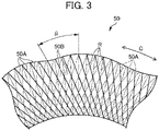
- FIG. 3 is a view for explaining the organic fiber cord layer constituting the flipper 50, and is a virtual view in the case of viewing the flipper 50 arranged within the tire 1 from the outer side in the tire-width direction towards the inner side in the tire-width direction.
- the flipper 50 is configured to include a plurality of cords 50A formed by twisting together a plurality of organic fibers, and rubber 50B as topping rubber integrating by coating the plurality of cords 50A.
- the plurality of cords 50A constituting the third portion 53 of the flipper 50 is shown by solid lines.
- the plurality of cords 50A constituting the flipper extends obliquely to the radial direction R, and is arranged at intervals in the tire circumferential direction C in the oblique state.
- the angle ⁇ formed by the radial direction R of the tire 1 and the extending direction of the cord 50A of the flipper 50 is preferably at least 20° and no more than 50°.
- the ply cords constituting the carcass ply 23 are arranged radially (radial direction) from the center of the tire 1. Consequently, in the present embodiment, the angle ⁇ formed by the extending direction of the ply cords of the carcass ply 23 and the extending direction of the cord 50A of the flipper 50 is at least 20° and no more than 50°.
- the flipper 50 is rolled back at the bead core 21. Consequently, the plurality of cords 50A constituting the first portion 51 of the flipper 50 slopes relative to the radial direction R as shown by the dashed line, in the opposite direction to the plurality of cords 50A constituting the third portion 53. Also in the first portion 51, the angle ⁇ formed by the radial direction R of the tire 1 and the extending direction of the cords 50A of the flipper 50 is preferably at least 20° and no more than 50°.
- the side-wall 12 includes the side-wall rubber 30 arranged on the outer side in the width direction of the carcass ply 23.
- the side-wall rubber 30 is a rubber member configuring the outer wall surface of the tire 1.
- the side-wall rubber 30 has a tire-radial direction outside end 30A and tire-radial direction inside end 30B.
- This side-wall rubber 30 is a portion which bends the most upon the tire 1 exhibiting a cushioning action, and usually flexible rubber having fatigue resistance is adopted therein.
- the tread 13 includes a steel belt 26 as a belt arranged on the outer side in the tire-radial direction of the carcass ply 23, a cap ply 27 arranged on the outer side in the tire-radial direction of the steel belt 26, and tread rubber 28 arranged on the outer side in the tire-radial direction of the cap ply 27.
- the steel belt 26 is configured by a plurality of steel cords covered by rubber. By providing the steel belts 26, the rigidity of the tire 1 is ensured, and the contact state of the road surface with the tread 13 improves.
- the two-layer structure steel belt (steel belt 261 on the inner side and steel belt 262 on the outer side) is provided; however, the number of steel belts 26 layered is not limited thereto. It should be noted that a belt made using a tire cord or the like made using aramid fiber may be used in place of the steel belt 26 made using steel belts. It should be noted that, in the two-layer structure steel belt 26 of the present embodiment, the steel belt 261 on the inner side is wider than the steel belt 262 on the outer side. Therefore, the tire-width direction outside end of the steel belt 261 on the inner side includes the tire-width direction outside end 26A of the steel belt 26.
- the cap ply 27 is a member arranged on the outer side in the tire-radial direction of the steel belt 26, and has a function as a belt reinforcement layer.
- the cap ply 27 is configured by an insulative organic fiber layer such as polyamide fiber, and is covered by topping rubber. By providing the cap ply 27, it is possible to achieve an improvement in durability and reduction in load noise while traveling.
- the tire-width direction outside end 27A of the cap ply 27 extends more to the outer side in the tire-width direction than the tire-width direction outside end 26A of the steel belt 26.
- the tread rubber 28 is a member constituting tire tread (contact patch with road surface R) 13C.
- the tread rubber 28 has a tire-width direction outside end 28A.
- a tread pattern (not shown) constituted by a plurality of grooves is provided to the tire tread 13C of the tread rubber 28.
- an inner liner 29 as a rubber layer constituting an inner wall surface of the tire 1 is provided to the tire inner cavity side of the carcass ply 23.
- the inner liner 29 is configured by air permeation resistant rubber, whereby the air inside the tire inner cavity is prevented from leaking to outside.
- the sidewall rubber 30 of the sidewall 12 extends towards the tread 13.
- the tread rubber 28 of the tread 13 extends towards the sidewall 12.
- the tread rubber 28 and sidewall rubber 30 enter a layered state, on the tire outer surface side of a partial region of the carcass ply 23.
- the sidewall rubber 30 and tread rubber 28 are in a layered state in order, on the tire outer surface side of the carcass ply 23.
- the rim strip rubber 32 and sidewall rubber 30 arranged on the outer side in the tire-radial direction of the rim strip rubber 32 are arranged.
- the tire-radial direction outside end 32A of the rim strip rubber 32 is arranged more to the outer side in the tire-radial direction than the tire-radial direction outside end 22A of the bead filler 22. It is thereby possible to more effectively suppress local deformation from occurring in the vicinity of the rim mounting part.
- a rim protector 33 which has an apex part 33A projecting to the outer side in the tire-width direction and continuously extending in a ring shape in the tire circumferential direction is provided in this transition region vicinity.
- the apex part 33A of the rim protector 33 is provided at a boundary portion between the rim strip rubber 32 and side-wall rubber 30.
- the position of the apex part 33A of the rim protector 33 matches the position of the tire-radial direction inside end 30B of the side-wall rubber 30.
- the rim protector 33 has a function of protecting the rim from external damage.
- the first end 31A of the chamfer 31 is arranged so as to be sandwiched between the ply body 24 of the carcass ply 23 and the inner liner 29.
- the second end 31B of the chamfer 31 is arranged so as to be sandwiched between the ply folding part 25 of the carcass ply 23 and the rim strip rubber 32.
- the ply folding part 25 extends until the tread 13. Then, the end 25A of the ply folding part 25 is arranged more to the inner side in the tire-width direction than the tire-width direction outside end 26A of the steel belt 26.
- the ply folding part 25 and steel belt 26 are in a layered state in order, on the tire outer surface side of the ply body 24. In this way, the ply folding part 25 and steel belt 26 have an overlapping portion in a member lamination direction from the tire inner cavity side towards the tire outer surface side. It is thereby possible to raise the rigidity of the tire overall.
- the ply folding part 25 and steel belt 26 do not necessarily have an overlapping portion in the member lamination direction from the tire inner cavity side toward the tire outer surface side.
- the flipper 50 and steel belt 26 do not have an overlapping portion in the member lamination direction from the tire inner cavity side toward the tire outer surface side. More specifically, the flipper 50 does not extend until the tread 13.
- the tire-radial direction outside end 51A of the flipper 50 is located at the sidewall 12. In other words, although the flipper 50 extends until the sidewall 12, it does not extend until the tread 13.
- the tire-width direction outside end 26A of the steel belt 26 of the tread 13 is located at the tread 13, and does not extend until the sidewall 12.
- An RFID tag 40 is embedded as an electrical component in the tire 1 of the present embodiment.
- the RFID tag 40 is a passive transponder equipped with an RFID chip and an antenna for performing communication with external equipment, and performs wireless communication with a reader (not illustrated) serving as the external equipment.
- a coil-shaped spring antenna, plate-shaped antenna, and various types of rod-shaped antennas can be used as the antenna.
- it may be an antenna formed by printing a predetermined pattern on a flexible substrate.
- the antenna is established at an antenna length optimized according to the frequency band, etc. to be used.
- identification information such as a manufacturing number and part number is stored.
- the RFID tag 40 is arranged so as to make contact with the flipper 50.
- the RFID tag 40 is hardly affected by distortion of the tire, etc. while travelling, due to the movement being restricted by the flipper 50 serving as a reinforced fiber layer. Consequently, it is possible to improve the durability of the RFID tag 40, without using additional components.
- the impact protection also improves. In other words, even if the tire receives external impact, since the carcass ply 23 as a fiber layer is present between the outer wall surface of the tire 1 and the RFID tag 40, it is possible to decrease the load on the RFID tag 40.
- the RFID tag 40 is arranged between the bead filler 22 and the flipper 50.
- the RFID tag 40 is provided between the bead filler 22 of high modulus and the flipper 50 which is a reinforced fiber layer, the periphery of the RFID tag 40 has little deformation, and stress hardly concentrates. Consequently, the RFID tag 40 is hardly damaged.
- the ply folding part 25 as a fiber layer and the third portion 53 of the flipper 50 as a reinforced fiber layer are present between the outer wall surface of the tire 1 and the RFID tag 40, it is possible to further decrease the load on the RFID tag 40.
- the RFID tag 40 is arranged between the inner side in the tire-width direction of the bead filler 22 and the first portion 51 of the flipper 50.
- the ply folding part 25 as a fiber layer, the third portion 53 of the flipper 50 as a reinforced fiber layer and the bead filler 22 are present between the outer wall surface of the tire 1 and the RFID tag 40. In this way, it is possible to further decrease the load on the RFID tag 40, by the RFID tag 40 being arranged at the inner side in the tire-width direction of the bead filler 22, and the distance from the outer wall surface of the tire 1 to the RFID tag 40 becoming farther.
- the RFID tag 40 is arranged more to an inner side in the tire-radial direction than the second end 31B of the chamfer 31. Even in the case of a force acting from outside, it is thereby possible to further decrease the load on the RFID tag 40. It should be noted that, in the present embodiment, the RFID tag 40 is arranged more to the outer side in the tire-radial direction than the first end 31A of the chamfer 31.
- the RFID tag 40 is preferably arranged at a position closer to the tire-radial direction outside end 22A than the tire-radial direction inside end 22B of the bead filler 22. More preferably, the RFID tag 40 has at least a part thereof arranged more to the outer side in the tire-radial direction than a position 10 mm to the inner side in the tire-radial direction from the tire-radial direction outside end 22A of the bead core. More preferably, the entire portion including the antenna of the RFID tag 40 is arranged more to the outer side in the tire-radial direction than a position 10 mm to the inner side in the tire-radial direction from the tire-radial direction outside end 22A of the bead core.
- the RFID tag 40 of the present embodiment is preferably arranged in an area range L1 of 10 mm from the tire-radial direction outside end 22A to the inner side in the tire-radial direction of the bead filler 22, as shown in FIGS. 1 and 2 .
- the RFID tag 40 preferably has at least a part which is arranged within a position 10 mm to the inner side in the tire-radial direction from the tire-radial direction outside end 22A of the bead filler 22.
- the RFID tag 40 preferably has at least a part which is arranged within a distance 2 mm to 10 mm to the inner side in the tire-radial direction from the tire-radial direction outside end 22A of the bead filler 22.
- FIG. 4 shows the result of examining the relationship of the communication distance relative to the separation distance of the RFID tag 40 from the tire-radial direction outside end 21A of the bead core 21.
- the communication distance on the vertical axis is a value indexing the communication distance with the longest communication distance as 100. It is sufficient if this value is at least 40, is preferably at least 60, and even more preferably at least 80.
- the bead core 21 is formed in a ring shape by laminating and winding a bead wire made of metal; therefore, it is a metal member having a particularly high possibility of adversely influencing communication. It is understood from FIG. 4 that the RFID tag 40 is better arranged at a position distanced as much as possible from the bead core 21. As shown in the present embodiment, it is possible to suppress the negative influence on communication, by arranging the RFID tag 40 in an area range L1 of 10 mm from the tire-radial direction outside end 22A of the bead filler 22. It is thereby possible to secure favorable communicability between the RFID tag 40 and an external reader.
- the RFID tag 40 of the present embodiment is installed in the tire constituent member before the vulcanization process in the manufacturing process of the tire 1. More specifically, the RFID tag 40 is installed in the bead filler 22 or flipper 50. At this time, the bead filler 22 and the topping rubber 50B of the flipper 50 are in the state of raw rubber prior to vulcanization. Consequently, using the adhesiveness of raw rubber, the RFD tag 40 is installed to the bead filler 22 or flipper 50. It should be noted that the RFID tag 40 may be installed using an adhesive or the like. Subsequently, the RFID tag 40 is inserted between the bead filler 22 and flipper 50. After inserted, the green tire in which each tire constituent member including the RFID tag 40 was assembled is vulcanized in the vulcanization step to produce the tire.
- the RFID tag 40 it is thereby possible to paste the RFID tag 40 to the flipper 50 as a reinforced fiber layer or the bead filler 22 covered by the raw rubber having rigidity and having adhesiveness, during tire production. Consequently, in the manufacturing process of the tire, the assembly work of the RFID tag 40 becomes easy.
- the RFID tag 40 embedded in the tire 1 often has a longitudinal direction if including an antenna, as shown as the RFID 40 in FIG. 8A described later.
- Such an RFID tag 40 is preferably embedded in the tire 1 so that the longitudinal direction thereof becomes the direction of the tangential line relative to the circumferential direction of the tire, for example, i.e. direction orthogonal to the paper plane in the cross-sectional views of FIGS. 1 and 2 .
- the RFID tag 40 is embedded in the tire as an electronic component
- the electronic component embedded in the tire is not limited to an RFID tag.
- it may be various electronic components such as a sensor which carries out wireless communication.
- the electronic component electrically contacts with a conductive member, a performance change in the electronic component arises, and there is a possibility of becoming difficult to maintain the characteristics of the electronic component.
- the electronic component may be damaged by excessive stress being applied. Consequently, even in the case of embedding various electronic components in a tire, it is possible to obtain the effects of the present invention.
- the electronic component may be a piezoelectric element or strain sensor.
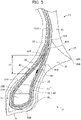
- FIG. 5 is an enlarged cross-sectional view of a half section in the tire-width direction of a tire 1 according to a first modified example of the present embodiment.
- the RFID tag 40 of the present modified example is arranged between the outer side in the tire-width direction of the bead filler 22 and the third portion 53 of the flipper 50.
- the RFID tag 40 is arranged so as to make contact with the flipper 50 Consequently, the RFID tag 40 is hardly affected by distortion of the tire, etc. while travelling, due to the movement being restricted by the flipper 50 serving as a reinforced fiber layer.
- the RFID tag 40 is arranged between the bead filler 22 of high modulus and the flipper 50 which is a reinforced fiber layer, the periphery of the RFID tag 40 has little deformation, and stress hardly concentrates. Consequently, the RFID tag 40 is hardly damaged.
- the RFID tag 40 is arranged at a position relatively close to the outer surface of the tire, the communication property between the outside and RFID tag 40 is good.
- FIG. 6 is an enlarged cross-sectional view of a half section in the tire-width direction of a tire 1 according to a second modified example of the present embodiment.
- the RFID tag 40 of the present modified example is arranged between the carcass ply 23 and the flipper 50. More specifically, the RFID tag 40 is arranged between the ply body 24 of the carcass ply 23 and the first portion 51 of the flipper 50.
- the RFID tag 40 is arranged so as to make contact with the flipper 50 Consequently, the RFID tag 40 is hardly affected by distortion of the tire, etc. while travelling, due to the movement being restricted by the flipper 50 serving as a reinforced fiber layer.
- the RFID tag 40 is provided between the carcass ply 23 as a fiber layer and the flipper 50 as a reinforced fiber layer, the periphery of the RFID tag 40 has little deformation, and stress hardly concentrates. Consequently, the RFID tag 40 is hardly damaged.
- the ply folding part 25 as a fiber layer, third portion 53 and first portion 51 of the flipper 50 as the reinforced fiber layer, and bead filler 22 are present.
- the RFID tag 40 being arranged at the inner side in the tire-width direction of the bead filler 22, and the distance from the outer wall surface of the tire 1 to the RFID tag 40 becoming farther.
- FIG. 7 is an enlarged cross-sectional view of a half section in the tire-width direction of a tire 1 according to a third modified example of the present embodiment.
- the RFID tag 40 of the present modified example is arranged between the carcass ply 23 and the flipper 50. More specifically, the RFID tag 40 is arranged between the ply folding part 25 of the carcass ply 23 and the third portion 53 of the flipper 50.
- the RFID tag 40 is arranged so as to make contact with the flipper 50 Consequently, the RFID tag 40 is hardly affected by distortion of the tire, etc. while travelling, due to the movement being restricted by the flipper 50 serving as a reinforced fiber layer.
- the RFID tag 40 is provided between the carcass ply 23 as a fiber layer and the flipper 50 as a reinforced fiber layer, the periphery of the RFID tag 40 has little deformation, and stress hardly concentrates. Consequently, the RFID tag 40 is hardly damaged.
- the RFID tag 40 is arranged at a position relatively close to the outer surface of the tire, the communication property between the outside and RFID tag 40 is favorable.
- the RFID tag 40 may be arranged more to the outer side in the tire-radial direction than the tire-radial direction outside end 22A of the bead filler 22.
- the flipper 50 may include an inner side part (first portion 51) covering the inner side in the tire-width direction of the bead core 21 and bead filler 22, and an outer side part (third portion 53) covering the outer side in the tire-width direction of the bead core 21 and bead filler 22, and the RFID tag 40 may be arranged between the inner side part (first portion 51) of the flipper 50 and the outer side part (third portion 53) of the flipper 50, more to the outer side in the tire-radial direction than the tire-radial direction outside end 22A of the bead filler 22.
- the inner side part (first portion 51) and outer side part (third portion 53) of the flipper 50 extend more to the outer side in the tire-radial direction than the tire-radial direction outside end 22A of the bead filler 22.
- the RFID tag 40 is arranged so as to make contact with the flipper 50. Consequently, the RFID tag 40 is hardly affected by distortion of the tire, etc. while travelling, due to the movement being restricted by the flipper 50 serving as a reinforced fiber layer.
- the RFID tag 40 is provided between the inner side part (first portion 51) and outer side part (third portion 53) of the flipper 50 which is a reinforced fiber layer, the periphery of the RFID tag 40 has little deformation, and stress hardly concentrates. Consequently, the RFID tag 40 is hardly damaged.
- the RFID tag 40 is hardly damaged.
- the RFID tag 40 is covered by a protective member 43 configured from a rubber sheet.
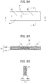
- FIG. 8A is a view showing the RFID tag 40 covered by the protective member 43 configured from a rubber sheet.
- the RFID tag 40 is covered and hidden by the rubber sheet 431 described later.
- FIG. 8B is a cross-sectional view along the line b-b in FIG. 8A
- FIG. 8C is a cross-sectional view along the line c-c in FIG. 8A .
- the RFID tag 40 is covered by the protective member 43, as shown in FIGS. 8A to 8C .
- the RFID tag 40 includes the RFID chip 41 and the antenna 42 for performing communication with external equipment.
- the antenna 42 a coil-shaped spring antenna, plate-shaped antenna, and various types of rod-shaped antennas can be used.
- it may be an antenna formed by printing a predetermined pattern on a flexible substrate.
- a coil-shaped spring antenna is the most preferable.
- the protective member 43 is configured from two rubber sheets 431, 432 which protect the RFID tag 40 by sandwiching.
- the protective member 43 is configured from rubber of predetermined modulus, for example.
- the modulus indicates 100% elongation modulus (M100) under a 23°C atmosphere, measured in accordance with "3.7 stress at a given elongation, S" of JIS K6251:2010.
- rubber at least having a higher modulus than the side wall rubber 30 is used.
- the modulus of the side wall rubber 30 as a reference, as the rubber used in the protective member 43, it is preferable to use rubber of a modulus 1.1 to 2 times.
- the protective member 43 may be configured from a short-fiber filler mixed rubber.
- the short-fiber filler for example, it is possible to use insulating short fibers like organic short fibers such as aramid short fibers and cellulose short fibers; inorganic short fibers such as ceramic short fibers as in alumina short fiber, and glass short fiber. By mixing such short-fiber fillers into rubber, it is possible to raise the strength of the rubber.
- a rubber sheet in the vulcanized state may be used as the protective member 43. The rubber sheet in a vulcanized state does not plastically deform as raw rubber, and thus can appropriately protect the RFID tag 40.
- an organic fiber layer from polyester fibers or polyamide fibers may be provided as the protective member 43. It is also possible to embed an organic fiber layer in the two rubber sheets 431, 432.
- the RFID tag 40 covered by the rubber sheets 431, 432 can be installed very easily. For example, at a desired position of each rubber member prior to vulcanization, it is possible to appropriately paste the RFID tag 40 covered by the rubber sheets 431, 432 using the adhesiveness of the raw rubber. In addition, by also establishing the rubber sheets 431, 432 as raw rubber prior to vulcanization, it is possible to more easily paste by employing the adhesiveness of the rubber sheets 431, 432 itself as well.
- the protective member 43 is not limited to the form configured by two rubber sheets 431, 432, and can adopt various forms.
- the rubber sheets constituting the protective member are covering at least part of the RFID tag 40, effects can be obtained such as an improvement in workability in the manufacturing process and stress mitigation.
- it may be a configuration wrapping one rubber sheet around the entire circumference of the RFID tag 40, or a configuration attaching the protective member in the form of a potting agent of high viscosity along the entire circumference of the RFID tag 40. Even if such a configuration, it will be possible to appropriately protect the RFID tag 40.
- the RFID tag 40 comes to be sandwiched between the carcass ply 23 and flipper 50, in a state covered by the protective member 43.
- the RFID tag 40 is protected by the existence of the protective member 43. Consequently, the durability of the RFID tag 40 further improves.
- the RFID tag 40 covered by the protective member 43 is embedded in the tire 1 so that the longitudinal direction thereof becomes the direction of the tangential line relative to the circumferential direction of the tire 1, i.e. direction orthogonal to the paper plane in the cross-sectional views of FIGS. 1 , 2 , and 5 to 7 .
- one surface of either one of the rubber sheets 431 and 432 is installed to the constituent members of the tire 1 prior to vulcanization.
- the RFID tag 40 is covered by the rubber sheets 431, 432.
- the workability in the manufacturing process thereby improves.
- effects such as mitigating the stress acting on the RFID tag 40 are obtained.
- the tire of the present invention can be adopted as various types of tires such as of a car, light truck, truck or bus; however, it is particularly suitable as a tire for a car. It should be noted that the present invention is not to be limited to the above-mentioned embodiment, and even if conducting modifications, improvements, etc. within a scope that can achieve the object of the present invention, will be encompassed in the scope of the present invention.
Landscapes
- Engineering & Computer Science (AREA)
- Mechanical Engineering (AREA)
- Physics & Mathematics (AREA)
- Health & Medical Sciences (AREA)
- Toxicology (AREA)
- General Physics & Mathematics (AREA)
- Theoretical Computer Science (AREA)
- Microelectronics & Electronic Packaging (AREA)
- Computer Hardware Design (AREA)
- Electromagnetism (AREA)
- General Health & Medical Sciences (AREA)
- Artificial Intelligence (AREA)
- Computer Vision & Pattern Recognition (AREA)
- Tires In General (AREA)
Abstract
Description
- The present invention relates to a tire in which an electronic component is embedded.
- Conventionally, a tire embedding an electronic component such as an RFID tag has been known. With such a tire, it is possible to carry out production management of the tire, usage history management, etc. by the RFID tag embedded in the tire and a reader as external equipment carrying out communication. For example, Patent Document 1 discloses a tire embedding an RF tag in the vicinity of a stiffener.
- Patent Document 1:
Japanese Unexamined Patent Application, Publication No. 2016-37236 - According to the technology illustrated in Patent Document 1, it is possible to carry out production management, shipping management, usage history management, etc. of tires. However, in the technology illustrated in Patent Document 1, the RF tag is arranged between the stiffener and side rubber, and a fiber layer such as a carcass ply does not exist between the RF tag and tire outer wall. Consequently, there is concern over the RF tag not being protected and becoming damaged in a case of the tire greatly distorting or a case of shock acting on the tire.
- The present invention has been made taking account of the above-mentioned problem, and an object thereof is to provide a tire which can protect an electronic component.
- A tire according to the present invention includes: a pair of beads having a bead core and a bead filler which extends to an outer side in a tire-radial direction of the bead core; a flipper which envelops at least part of the bead; a carcass ply which has a ply body extending from one bead to another bead, and a ply folding part which is folded back at the bead, and which envelopes the flipper; and an RFID tag as an electronic component embedded within the tire so as to make contact with the flipper.
- According to the present invention, it is possible to provide a tire which can protect an electronic component.
-
-
FIG. 1 is a view showing a half section in a tire-width direction of a tire according to a first embodiment; -
FIG. 2 is a partially enlarged cross-sectional view of the tire inFIG. 1 ; -
FIG. 3 is a view for explaining a flipper of the tire according to the above-mentioned embodiment; -
FIG. 4 is a view showing the relationship between the distance between a bead core and RFID tag, and the communication distance; -
FIG. 5 is a partially enlarged cross-sectional view of a tire according to a first modified example of the above embodiment;FIG. 6 is a partially enlarged cross-sectional view of a tire according to a second modified example of the above embodiment; -
FIG. 7 is a partially enlarged cross-sectional view of a tire according to a third modified example of the above embodiment;FIG. 8A is a view showing an RFID tag protected by a protective member in a tire according to a second embodiment;FIG. 8B is a view showing a cross section along the line b-b inFIG. 8A ; and -
FIG. 8C is a view showing a cross section along the line c-c inFIG. 8A . - Hereinafter, a first embodiment of the present invention will be explained while referencing the drawings.
FIG. 1 is a view showing a half section in a tire-width direction of a tire 1 according to the present embodiment. The basic structure of the tire 1 is left/right symmetric in the cross section of the tire-width direction; therefore, a cross-sectional view of the right half is shown herein. In the drawings, the reference symbol S1 is the tire equatorial plane. The tire equatorial plane S1 is a plane orthogonal to the tire rotation axis (tire meridian), and is positioned in the center of the tire-width direction. - Herein, tire-width direction is a direction parallel to the tire rotation axis, and is the left/right direction of the paper plane of the cross-sectional view in
FIG. 1 . InFIG. 1 , it is illustrated as the tire-width direction X. Then, inner side of tire-width direction is a direction approaching the tire equatorial plane S1, and is the left side of the paper plane inFIG. 1 . Outer side of tire-width direction is a direction distancing from the tire equatorial plane S1, and is the right side of the paper plane inFIG. 1 . In addition, tire-radial direction is a direction perpendicular to the tire rotation axis, and is the vertical direction in the paper plane ofFIG. 1 . InFIG. 1 , it is illustrated as the tire-radial direction Y. Then, outer side of tire-radial direction is a direction distancing from the tire rotation axis, and is the upper side of the paper plane inFIG. 1 . Inner side of tire-radial direction is a direction approaching the tire rotation axis, and is the lower side of the paper plane inFIG. 1 . - It should be noted that the cross-sectional view of
FIG. 1 is a tire-width direction cross-sectional view (tire meridian axis cross-sectional view) in a state mounting the tire to a standard rim, and filling the standard internal pressure. It should be noted that standard rim indicates a rim serving as a standard decided by JATMA to correspond to the tire size. In addition, standard internal pressure is 180 kPa in the case of the tire being for a passenger vehicle, for example. - It should be noted that the aforementioned contents similarly apply to
FIGS. 2 , and5 to 7 . - The tire 1 is a tire for passenger cars, for example, and includes a pair of
beads 11 provided at both sides in the tire-width direction, asidewall 12 which extends from each of thebeads 11 to the outer side in the tire-radial direction; andannular tread 13 which connects to the outer side in the tire-radial direction of each of thesidewalls 12 and extends in the circumferential direction of the tire constituting the tire tread (contact patch with road surface R) 13C. -
FIG. 2 shows an enlarged cross-sectional view in the periphery in a tire-radial direction inside region of thebead 11 andsidewall 12 of the tire 1 of the present embodiment shown inFIG. 1 . - The
bead 11 includes abead core 21, andbead filler 22 extending to the outer side in the tire-radial direction of thebead core 21. - The
bead core 21 is an annular member formed by wrapping around several times bead wires made of metal coated with rubber, and is a member which plays a role of fixing the tire 1 filled with air to the rim (not shown) of a wheel. - The
bead filler 22 is a rubber member of tapered tip shape, extending to the outer side in the tire-radial direction of thebead core 21. Thebead filler 22 has a tire-radial direction outsideend 22A and a tire-radial direction insideend 22B. The tire-radial direction insideend 22B of thebead filler 22 contacts with the tire-radial direction outsideend 21A of thebead core 21. Thebead filler 22 is a member provided in order to raise the rigidity of the bead peripheral part and to ensure high maneuverability and stability. Thebead filler 22 is configured by rubber of higher hardness than the surrounding rubber members, for example. The modulus of rubber constituting the bead filler is higher than at least the modulus of rubber constituting theinner liner 29 described later and the rubber constituting thesidewall 30. - A
carcass ply 23 bridging between the pair ofbeads 11 is embedded inside of the tire 1. Thecarcass ply 23 configures a ply serving as the backbone of the tire 1, and is embedded within the tire 1, in a form passing through the pair ofsidewalls 12 and thetread 13 between the pair ofbeads 11. - The
carcass ply 23 includes theply body 24 which extends from onebead core 21 to the otherbead core 21 and exists between thetread 13 andbead 11; and theply folding part 25 which is folded back around thebead core 21. In the present embodiment, theply folding part 25 is overlapped with theply body 24 in the region of thesidewall 12. Aply folding part 25 has anend 25A. In the present embodiment, theend 25A of theply folding part 25 is positioned in a region of thesidewall 12. - The
carcass ply 23 is configured by a plurality of ply cords extending in the tire-width direction. In addition, a plurality of ply cords is arranged side by side in a tire circumferential direction. This ply cord is configured by an insulated organic fiber cord such as polyester or polyamide, or the like, and is covered by topping rubber. In the present embodiment, the ply coating constituting thecarcass ply 23 is arranged radially (radial direction) from the center of the tire 1. In other words, the tire 1 of the present embodiment is a so-called radial tire in which ply cords are arranged so as to extend radially. - It should be noted that the carcass ply 23 of the present embodiment is a single-layer structure carcass ply 23 including one layer of a
ply body 24. However, the carcass ply 23 may be a multi-layer structure carcass ply 23 including a plurality of layers ofply body 24. - The
bead 11 further includes achamfer 31, andrim strip rubber 32 arranged at the tire-width direction outer side of thechamfer 31. - The
chafer 31 is provided so as to cover the carcass ply 23 provided around thebead core 21. In more detail, thechafer 31 is provided so as to cover the inner side in the tire-width direction, inner side in the tire-radial direction and outer side in the tire-width direction of the carcass ply 23 at the periphery of thebead core 21. Thechafer 31 has afirst end 31A arranged on the inner side in the tire-width direction of theply body 24, and asecond end 31B arranged at the outer side in the tire-width direction of theply folding part 25 of thecarcass ply 23. Thechafer 31 is configured from rubber into which fibers were kneaded, or rubber of high modulus, for example, and the relative strength is high among constituent members constituting the tire 1. For example, the strength is higher than theinner liner 29 and side-wall rubber 30 described later. - The
rim strip rubber 32 is a rubber member arranged on the outer side in the tire-width direction of thechafer 31 and theply folding part 25 of thecarcass ply 23, and upon the tire 1 being mounted to a wheel, the outer side in the tire-width direction thereof makes contact with the rim (not shown) of the wheel. Therim strip rubber 32 has a tire-radial direction outsideend 32A and tire-radial direction insideend 32B. The outer side in the tire-radial direction of thisrim strip rubber 32 connects to the side-wall rubber 30. - The
flipper 50 is arranged at thebead 11. Theflipper 50 is a reinforced fiber layer provided so as to cover thebead core 21. Theflipper 50 raises the rigidity of the bead overall. The pressure bonding property between thebead 11 and rid is high, which can thereby suppress rim deviation of thebead 11. Theflipper 50 is arranged to as to be sandwiched between thebead core 21 and carcass ply 23 provided around thebead core 21. In more detail, theflipper 50 includes afirst portion 51 cover the inner side in the tire-width direction of thebead core 21,second portion 52 covering the inner side in the tire-radial direction, and third portion covering the outer side in the tire-width direction. Theflipper 50 envelops at least part of thebead 11. In the present embodiment, theflipper 50 envelops at least part of thebead core 21 constituting thebead 11, by thefirst portion 51,second portion 52 andthird portion 53. In the present embodiment, theflipper 50 envelops thebead core 21 constituting thebead 11, and thebead filler 22. - The
first portion 51 extends more to the outer side in the tire-radial direction than thebead core 21. In the present embodiment, a tire-radial direction outsideend 51A of thefirst portion 51 is arranged more to the outer side in the tire-radial direction than the tire-radial direction outsideend 22A of thebead filler 22. Thefirst portion 51 is arranged so as to cover the inner side in the tire-width direction of thebead filler 22, in addition to the inner side in the tire-width direction of thebead core 21. - The
first portion 51 has a portion arranged to be sandwiched between the inner side in the tire-width direction of thebead core 21 and theply body 24, and a portion arranged to be sandwiched between the inner side in the tire-width direction of thebead filler 22 and theply body 24. In the present embodiment, thefirst portion 51 further includes: a portion arranged to be sandwiched between theply body 24 and thethird portion 53 of theflipper 50, and a portion arranged to be sandwiched between theply body 24 and theply folding part 25. - It should be noted that, in the present embodiment, the tire-radial direction outside
end 51A of thefirst portion 51 is arranged at a tire-radial direction position of thesidewall 12 corresponding to a portion at which the tire inner cavity part is the widest in the tire-width direction. In this way, the tire-radial direction outsideend 51A of thefirst portion 51 is preferably arranged at the tire-radial direction portion corresponding to a portion at which the tire inner cavity part is the widest in the tire-width direction, or more to the inner side in the tire-radial direction than this. In addition, the tire-radial direction outsideend 51A of thefirst portion 51 may be arranged at a tire-radial direction position similarly to the tire-radial direction outsideend 22A of thebead filler 22, or more to the inner side in the tire-radial direction than this. It is sufficient so long as theflipper 50 envelops at least part of thebead 11. The tire-radial direction position of the tire-radial direction outsideend 51A of thefirst portion 51 is adjusted according to the rigidity demanded in the tire 1. - The
second portion 52 is arranged to be sandwiched between the inner side in the tire-radial direction of thebead core 21 and thecarcass ply 23. - The
third portion 53 extends more to the outer side in the tire-radial direction than thebead core 21. In the present embodiment, the tire-radial direction outsideend 53A of thethird portion 53 is arranged more to the outer side in the tire-radial direction than the tire-radial direction outsideend 22A of thebead filler 22. Thethird portion 53 is arranged so as to cover the outer side in the tire-width direction of thebead filler 22, in addition to the outer side in the tire-width direction of thebead core 21. - The
third portion 53 has a portion arranged to be sandwiched between the outer side in the tire-width direction of thebead core 21 and theply folding part 25, and a portion arranged to be sandwiched between the outer side in the tire-width direction of thebead filler 22 and theply folding part 25. In the present embodiment, thethird portion 53 further has a portion arranged to be sandwiched between theply folding part 25 and thefirst portion 51 of theflipper 50. - It should be noted that, in the present embodiment, the tire-radial direction outside
end 53A of thethird portion 53 is arranged more to the inner side in the tire-radial direction than the tire-radial direction position of thesidewall 12 corresponding to the portion at which the tire inner cavity part is widest in the tire-width direction. The tire-radial direction outsideend 53A of thethird portion 53 is preferably arranged at a tire-radial direction position corresponding to a portion at which the tire inner cavity part is widest in the tire-width direction, or more to the inner side in the tire-radial direction than this. In addition, the tire-radial direction outsideend 53A of thethird portion 53 may be arranged at a tire-radial direction position similarly to the tire-radial direction outsideend 22A of thebead filler 22, or more to the inner side in the tire-radial direction than this. It is sufficient so long as theflipper 50 envelops at least part of thebead 11. The tire-radial direction position of the tire-radial direction outsideend 53A of thethird portion 53 is adjusted according to the rigidity demanded in the tire 1. - It should be noted that, in the present embodiment, the tire-radial direction outside
end 51A of thefirst portion 51 is positioned more to the outer side in the tire-radial direction than the tire-radial direction outsideend 53A of thethird portion 53. Therefore, the tire-radial direction outsideend 51A of thefirst portion 51 constitutes the tire-radial direction outside end of theflipper 50. It should be noted that the tire-radial direction outsideend 53A of thethird portion 53 may be located more to the outer side in the tire-radial direction than the tire-radial direction outsideend 51A of thefirst portion 51. In this case, the tire-radial direction outsideend 53A of thethird portion 53 constitutes the tire-radial direction outside end of theflipper 50. - The
flipper 50 of the present embodiment is configured from an organic fiber cord layer containing insulative organic fibers such as polyester and polyamide.FIG. 3 is a view for explaining the organic fiber cord layer constituting theflipper 50, and is a virtual view in the case of viewing theflipper 50 arranged within the tire 1 from the outer side in the tire-width direction towards the inner side in the tire-width direction. Theflipper 50 is configured to include a plurality ofcords 50A formed by twisting together a plurality of organic fibers, andrubber 50B as topping rubber integrating by coating the plurality ofcords 50A. InFIG. 3 , the plurality ofcords 50A constituting thethird portion 53 of theflipper 50 is shown by solid lines. - As shown in
FIG. 3 , the plurality ofcords 50A constituting the flipper extends obliquely to the radial direction R, and is arranged at intervals in the tire circumferential direction C in the oblique state. The angle θ formed by the radial direction R of the tire 1 and the extending direction of thecord 50A of theflipper 50 is preferably at least 20° and no more than 50°. It should be noted that, in the present embodiment, the ply cords constituting the carcass ply 23 are arranged radially (radial direction) from the center of the tire 1. Consequently, in the present embodiment, the angle θ formed by the extending direction of the ply cords of thecarcass ply 23 and the extending direction of thecord 50A of theflipper 50 is at least 20° and no more than 50°. - It should be noted that the
flipper 50 is rolled back at thebead core 21. Consequently, the plurality ofcords 50A constituting thefirst portion 51 of theflipper 50 slopes relative to the radial direction R as shown by the dashed line, in the opposite direction to the plurality ofcords 50A constituting thethird portion 53. Also in thefirst portion 51, the angle θ formed by the radial direction R of the tire 1 and the extending direction of thecords 50A of theflipper 50 is preferably at least 20° and no more than 50°. - The side-
wall 12 includes the side-wall rubber 30 arranged on the outer side in the width direction of thecarcass ply 23. - The side-
wall rubber 30 is a rubber member configuring the outer wall surface of the tire 1. The side-wall rubber 30 has a tire-radial direction outsideend 30A and tire-radial direction insideend 30B. This side-wall rubber 30 is a portion which bends the most upon the tire 1 exhibiting a cushioning action, and usually flexible rubber having fatigue resistance is adopted therein. - The
tread 13 includes asteel belt 26 as a belt arranged on the outer side in the tire-radial direction of thecarcass ply 23, acap ply 27 arranged on the outer side in the tire-radial direction of thesteel belt 26, and treadrubber 28 arranged on the outer side in the tire-radial direction of thecap ply 27. - The
steel belt 26 is configured by a plurality of steel cords covered by rubber. By providing thesteel belts 26, the rigidity of the tire 1 is ensured, and the contact state of the road surface with thetread 13 improves. In the present embodiment, the two-layer structure steel belt (steel belt 261 on the inner side andsteel belt 262 on the outer side) is provided; however, the number ofsteel belts 26 layered is not limited thereto. It should be noted that a belt made using a tire cord or the like made using aramid fiber may be used in place of thesteel belt 26 made using steel belts. It should be noted that, in the two-layerstructure steel belt 26 of the present embodiment, thesteel belt 261 on the inner side is wider than thesteel belt 262 on the outer side. Therefore, the tire-width direction outside end of thesteel belt 261 on the inner side includes the tire-width direction outsideend 26A of thesteel belt 26. - The cap ply 27 is a member arranged on the outer side in the tire-radial direction of the
steel belt 26, and has a function as a belt reinforcement layer. The cap ply 27 is configured by an insulative organic fiber layer such as polyamide fiber, and is covered by topping rubber. By providing thecap ply 27, it is possible to achieve an improvement in durability and reduction in load noise while traveling. In the present embodiment, the tire-width direction outsideend 27A of the cap ply 27 extends more to the outer side in the tire-width direction than the tire-width direction outsideend 26A of thesteel belt 26. - The
tread rubber 28 is a member constituting tire tread (contact patch with road surface R) 13C. Thetread rubber 28 has a tire-width direction outsideend 28A. A tread pattern (not shown) constituted by a plurality of grooves is provided to thetire tread 13C of thetread rubber 28. - In the
bead 11,sidewall 12 andtread 13, aninner liner 29 as a rubber layer constituting an inner wall surface of the tire 1 is provided to the tire inner cavity side of thecarcass ply 23. Theinner liner 29 is configured by air permeation resistant rubber, whereby the air inside the tire inner cavity is prevented from leaking to outside. - Herein, as shown in
FIG. 1 , thesidewall rubber 30 of thesidewall 12 extends towards thetread 13. On the other hand, thetread rubber 28 of thetread 13 extends towards thesidewall 12. As a result thereof, thetread rubber 28 andsidewall rubber 30 enter a layered state, on the tire outer surface side of a partial region of thecarcass ply 23. In more detail, in a region in which thesidewall rubber 30 and treadrubber 28 both exist, i.e. movement region of thesidewall 12 andtread 13, thesidewall rubber 30 and treadrubber 28 are in a layered state in order, on the tire outer surface side of thecarcass ply 23. - As shown in
FIGS. 1 and2 , on the outer side in the tire-width direction of thebead 11 and carcass ply 23 of thesidewall 12, therim strip rubber 32 andsidewall rubber 30 arranged on the outer side in the tire-radial direction of therim strip rubber 32 are arranged. Then, in the present embodiment, the tire-radial direction outsideend 32A of therim strip rubber 32 is arranged more to the outer side in the tire-radial direction than the tire-radial direction outsideend 22A of thebead filler 22. It is thereby possible to more effectively suppress local deformation from occurring in the vicinity of the rim mounting part. - In addition, as shown in
FIGS. 1 and2 , in the vicinity of the movement region of thebead 11 andsidewall 12, therim strip rubber 32 andsidewall rubber 30 enter a layered state in order on the tire outer surface side of thecarcass ply 23. In addition, arim protector 33 which has anapex part 33A projecting to the outer side in the tire-width direction and continuously extending in a ring shape in the tire circumferential direction is provided in this transition region vicinity. In the present embodiment, theapex part 33A of therim protector 33 is provided at a boundary portion between therim strip rubber 32 and side-wall rubber 30. In other words, the position of theapex part 33A of therim protector 33 matches the position of the tire-radial direction insideend 30B of the side-wall rubber 30. Therim protector 33 has a function of protecting the rim from external damage. - In addition, as shown in
FIGS. 1 and2 , thefirst end 31A of thechamfer 31 is arranged so as to be sandwiched between theply body 24 of thecarcass ply 23 and theinner liner 29. Thesecond end 31B of thechamfer 31 is arranged so as to be sandwiched between theply folding part 25 of thecarcass ply 23 and therim strip rubber 32. - In the present embodiment, as shown in
FIG. 1 , theply folding part 25 extends until thetread 13. Then, theend 25A of theply folding part 25 is arranged more to the inner side in the tire-width direction than the tire-width direction outsideend 26A of thesteel belt 26. In other words, in the tire-width direction outside region of thetread 13, theply folding part 25 andsteel belt 26 are in a layered state in order, on the tire outer surface side of theply body 24. In this way, theply folding part 25 andsteel belt 26 have an overlapping portion in a member lamination direction from the tire inner cavity side towards the tire outer surface side. It is thereby possible to raise the rigidity of the tire overall. However, theply folding part 25 andsteel belt 26 do not necessarily have an overlapping portion in the member lamination direction from the tire inner cavity side toward the tire outer surface side. - Herein, as shown in
FIG. 1 , theflipper 50 andsteel belt 26 do not have an overlapping portion in the member lamination direction from the tire inner cavity side toward the tire outer surface side. More specifically, theflipper 50 does not extend until thetread 13. In the present embodiment, the tire-radial direction outsideend 51A of theflipper 50 is located at thesidewall 12. In other words, although theflipper 50 extends until thesidewall 12, it does not extend until thetread 13. On the other hand, the tire-width direction outsideend 26A of thesteel belt 26 of thetread 13 is located at thetread 13, and does not extend until thesidewall 12. In this way, since thesteel belt 26 andflipper 50 do not have an overlapping portion, even in the case of a large load acting on the tire due to puncture or the like, and a great force acting on thesteel belt 26, it is possible to suppress this force from transmitting directly to theflipper 50. - An
RFID tag 40 is embedded as an electrical component in the tire 1 of the present embodiment. TheRFID tag 40 is a passive transponder equipped with an RFID chip and an antenna for performing communication with external equipment, and performs wireless communication with a reader (not illustrated) serving as the external equipment. As the antenna, a coil-shaped spring antenna, plate-shaped antenna, and various types of rod-shaped antennas can be used. For example, it may be an antenna formed by printing a predetermined pattern on a flexible substrate. The antenna is established at an antenna length optimized according to the frequency band, etc. to be used. In a storage part inside the RFID chip, identification information such as a manufacturing number and part number is stored. - As shown in
FIG. 1 andFIG. 2 , theRFID tag 40 is arranged so as to make contact with theflipper 50. According to this configuration, theRFID tag 40 is hardly affected by distortion of the tire, etc. while travelling, due to the movement being restricted by theflipper 50 serving as a reinforced fiber layer. Consequently, it is possible to improve the durability of theRFID tag 40, without using additional components. In addition, according to the present embodiment, the impact protection also improves. In other words, even if the tire receives external impact, since the carcass ply 23 as a fiber layer is present between the outer wall surface of the tire 1 and theRFID tag 40, it is possible to decrease the load on theRFID tag 40. - In the present embodiment, specifically, the
RFID tag 40 is arranged between thebead filler 22 and theflipper 50. In this way, since theRFID tag 40 is provided between thebead filler 22 of high modulus and theflipper 50 which is a reinforced fiber layer, the periphery of theRFID tag 40 has little deformation, and stress hardly concentrates. Consequently, theRFID tag 40 is hardly damaged. Then, since theply folding part 25 as a fiber layer and thethird portion 53 of theflipper 50 as a reinforced fiber layer are present between the outer wall surface of the tire 1 and theRFID tag 40, it is possible to further decrease the load on theRFID tag 40. - In the present embodiment, more specifically, the
RFID tag 40 is arranged between the inner side in the tire-width direction of thebead filler 22 and thefirst portion 51 of theflipper 50. In other words, theply folding part 25 as a fiber layer, thethird portion 53 of theflipper 50 as a reinforced fiber layer and thebead filler 22 are present between the outer wall surface of the tire 1 and theRFID tag 40. In this way, it is possible to further decrease the load on theRFID tag 40, by theRFID tag 40 being arranged at the inner side in the tire-width direction of thebead filler 22, and the distance from the outer wall surface of the tire 1 to theRFID tag 40 becoming farther. - It should be noted that, in the present embodiment, the
RFID tag 40 is arranged more to an inner side in the tire-radial direction than thesecond end 31B of thechamfer 31. Even in the case of a force acting from outside, it is thereby possible to further decrease the load on theRFID tag 40. It should be noted that, in the present embodiment, theRFID tag 40 is arranged more to the outer side in the tire-radial direction than thefirst end 31A of thechamfer 31. - As shown in
FIGS. 1 and2 , theRFID tag 40 is preferably arranged at a position closer to the tire-radial direction outsideend 22A than the tire-radial direction insideend 22B of thebead filler 22. More preferably, theRFID tag 40 has at least a part thereof arranged more to the outer side in the tire-radial direction than aposition 10 mm to the inner side in the tire-radial direction from the tire-radial direction outsideend 22A of the bead core. More preferably, the entire portion including the antenna of theRFID tag 40 is arranged more to the outer side in the tire-radial direction than aposition 10 mm to the inner side in the tire-radial direction from the tire-radial direction outsideend 22A of the bead core. For example, theRFID tag 40 of the present embodiment is preferably arranged in an area range L1 of 10 mm from the tire-radial direction outsideend 22A to the inner side in the tire-radial direction of thebead filler 22, as shown inFIGS. 1 and2 . In other words, theRFID tag 40 preferably has at least a part which is arranged within aposition 10 mm to the inner side in the tire-radial direction from the tire-radial direction outsideend 22A of thebead filler 22. For example, theRFID tag 40 preferably has at least a part which is arranged within a distance 2 mm to 10 mm to the inner side in the tire-radial direction from the tire-radial direction outsideend 22A of thebead filler 22. -
FIG. 4 shows the result of examining the relationship of the communication distance relative to the separation distance of theRFID tag 40 from the tire-radial direction outsideend 21A of thebead core 21. It should be noted that the communication distance on the vertical axis is a value indexing the communication distance with the longest communication distance as 100. It is sufficient if this value is at least 40, is preferably at least 60, and even more preferably at least 80. - The
bead core 21 is formed in a ring shape by laminating and winding a bead wire made of metal; therefore, it is a metal member having a particularly high possibility of adversely influencing communication. It is understood fromFIG. 4 that theRFID tag 40 is better arranged at a position distanced as much as possible from thebead core 21. As shown in the present embodiment, it is possible to suppress the negative influence on communication, by arranging theRFID tag 40 in an area range L1 of 10 mm from the tire-radial direction outsideend 22A of thebead filler 22. It is thereby possible to secure favorable communicability between theRFID tag 40 and an external reader. - Herein, the
RFID tag 40 of the present embodiment is installed in the tire constituent member before the vulcanization process in the manufacturing process of the tire 1. More specifically, theRFID tag 40 is installed in thebead filler 22 orflipper 50. At this time, thebead filler 22 and the toppingrubber 50B of theflipper 50 are in the state of raw rubber prior to vulcanization. Consequently, using the adhesiveness of raw rubber, theRFD tag 40 is installed to thebead filler 22 orflipper 50. It should be noted that theRFID tag 40 may be installed using an adhesive or the like. Subsequently, theRFID tag 40 is inserted between thebead filler 22 andflipper 50. After inserted, the green tire in which each tire constituent member including theRFID tag 40 was assembled is vulcanized in the vulcanization step to produce the tire. - In the present embodiment, it is thereby possible to paste the
RFID tag 40 to theflipper 50 as a reinforced fiber layer or thebead filler 22 covered by the raw rubber having rigidity and having adhesiveness, during tire production. Consequently, in the manufacturing process of the tire, the assembly work of theRFID tag 40 becomes easy. - It should be noted that the
RFID tag 40 embedded in the tire 1 often has a longitudinal direction if including an antenna, as shown as theRFID 40 inFIG. 8A described later. Such anRFID tag 40 is preferably embedded in the tire 1 so that the longitudinal direction thereof becomes the direction of the tangential line relative to the circumferential direction of the tire, for example, i.e. direction orthogonal to the paper plane in the cross-sectional views ofFIGS. 1 and2 . By embedding in this way, stress will hardly act on theRFID tag 40 when the tire 1 deforms. - It should be noted that, in the present embodiment, although the
RFID tag 40 is embedded in the tire as an electronic component, the electronic component embedded in the tire is not limited to an RFID tag. For example, it may be various electronic components such as a sensor which carries out wireless communication. In addition, when the electronic component electrically contacts with a conductive member, a performance change in the electronic component arises, and there is a possibility of becoming difficult to maintain the characteristics of the electronic component. In addition, there is a possibility of the electronic component being damaged by excessive stress being applied. Consequently, even in the case of embedding various electronic components in a tire, it is possible to obtain the effects of the present invention. For example, the electronic component may be a piezoelectric element or strain sensor. -
FIG. 5 is an enlarged cross-sectional view of a half section in the tire-width direction of a tire 1 according to a first modified example of the present embodiment. - As shown in
FIG. 5 , theRFID tag 40 of the present modified example is arranged between the outer side in the tire-width direction of thebead filler 22 and thethird portion 53 of theflipper 50. - Also in the present modified example, the
RFID tag 40 is arranged so as to make contact with theflipper 50 Consequently, theRFID tag 40 is hardly affected by distortion of the tire, etc. while travelling, due to the movement being restricted by theflipper 50 serving as a reinforced fiber layer. - In addition, in the present modified example, since the
RFID tag 40 is arranged between thebead filler 22 of high modulus and theflipper 50 which is a reinforced fiber layer, the periphery of theRFID tag 40 has little deformation, and stress hardly concentrates. Consequently, theRFID tag 40 is hardly damaged. - Then, in the present modified example, between the outer wall surface of the tire 1 and the
RFID tag 40, since theply folding part 25 as a fiber layer and thethird portion 53 of theflipper 50 as the reinforced fiber layer are present, it is possible to decrease the load on theRFID tag 40. - Then, in the present modified example, since the
RFID tag 40 is arranged at a position relatively close to the outer surface of the tire, the communication property between the outside andRFID tag 40 is good. -
FIG. 6 is an enlarged cross-sectional view of a half section in the tire-width direction of a tire 1 according to a second modified example of the present embodiment. - As shown in
FIG. 6 , theRFID tag 40 of the present modified example is arranged between thecarcass ply 23 and theflipper 50. More specifically, theRFID tag 40 is arranged between theply body 24 of thecarcass ply 23 and thefirst portion 51 of theflipper 50. - Also in the present modified example, the
RFID tag 40 is arranged so as to make contact with theflipper 50 Consequently, theRFID tag 40 is hardly affected by distortion of the tire, etc. while travelling, due to the movement being restricted by theflipper 50 serving as a reinforced fiber layer. - Then, in the present modified example, since the
RFID tag 40 is provided between the carcass ply 23 as a fiber layer and theflipper 50 as a reinforced fiber layer, the periphery of theRFID tag 40 has little deformation, and stress hardly concentrates. Consequently, theRFID tag 40 is hardly damaged. In addition, during vulcanization and during use, it is possible to prevent theRFID tag 40 from directly pressing the surrounding rubber members such as theinner liner 29 andbead filler 22. Consequently, the surrounding rubber members are hardly damaged. - Then, in the present modified example, between the outer wall surface of the tire 1 and the
RFID tag 40, theply folding part 25 as a fiber layer,third portion 53 andfirst portion 51 of theflipper 50 as the reinforced fiber layer, andbead filler 22 are present. In this way, it is possible to further decrease the load on theRFID tag 40, by theRFID tag 40 being arranged at the inner side in the tire-width direction of thebead filler 22, and the distance from the outer wall surface of the tire 1 to theRFID tag 40 becoming farther. -
FIG. 7 is an enlarged cross-sectional view of a half section in the tire-width direction of a tire 1 according to a third modified example of the present embodiment. - As shown in
FIG. 7 , theRFID tag 40 of the present modified example is arranged between thecarcass ply 23 and theflipper 50. More specifically, theRFID tag 40 is arranged between theply folding part 25 of thecarcass ply 23 and thethird portion 53 of theflipper 50. - Also in the present modified example, the
RFID tag 40 is arranged so as to make contact with theflipper 50 Consequently, theRFID tag 40 is hardly affected by distortion of the tire, etc. while travelling, due to the movement being restricted by theflipper 50 serving as a reinforced fiber layer. - Then, also in the present modified example, since the
RFID tag 40 is provided between the carcass ply 23 as a fiber layer and theflipper 50 as a reinforced fiber layer, the periphery of theRFID tag 40 has little deformation, and stress hardly concentrates. Consequently, theRFID tag 40 is hardly damaged. In addition, during vulcanization and during use, it is possible to prevent theRFID tag 40 from directly pressing the surrounding rubber members such as theinner liner 29 andbead filler 22. Consequently, the surrounding rubber members are hardly damaged. - Then, in the present modified example, between the outer wall surface of the tire 1 and the
RFID tag 40, since theply folding part 25 as a fiber layer is present, it is possible to decrease the load on theRFID tag 40. - Then, in the present modified example, since the
RFID tag 40 is arranged at a position relatively close to the outer surface of the tire, the communication property between the outside andRFID tag 40 is favorable. - It should be noted that the
RFID tag 40 may be arranged more to the outer side in the tire-radial direction than the tire-radial direction outsideend 22A of thebead filler 22. For example, theflipper 50 may include an inner side part (first portion 51) covering the inner side in the tire-width direction of thebead core 21 andbead filler 22, and an outer side part (third portion 53) covering the outer side in the tire-width direction of thebead core 21 andbead filler 22, and theRFID tag 40 may be arranged between the inner side part (first portion 51) of theflipper 50 and the outer side part (third portion 53) of theflipper 50, more to the outer side in the tire-radial direction than the tire-radial direction outsideend 22A of thebead filler 22. In this case, the inner side part (first portion 51) and outer side part (third portion 53) of theflipper 50 extend more to the outer side in the tire-radial direction than the tire-radial direction outsideend 22A of thebead filler 22. - Also in such a configuration, the
RFID tag 40 is arranged so as to make contact with theflipper 50. Consequently, theRFID tag 40 is hardly affected by distortion of the tire, etc. while travelling, due to the movement being restricted by theflipper 50 serving as a reinforced fiber layer. - Then, in such a configuration, since the
RFID tag 40 is provided between the inner side part (first portion 51) and outer side part (third portion 53) of theflipper 50 which is a reinforced fiber layer, the periphery of theRFID tag 40 has little deformation, and stress hardly concentrates. Consequently, theRFID tag 40 is hardly damaged. In addition, during vulcanization and during use, it is possible to prevent theRFID tag 40 from directly pressing the surrounding rubber members such as theinner liner 29 andbead filler 22. Consequently, the surrounding rubber members are hardly damaged. - Furthermore, if such a configuration, by a simple operation such as arranging the
RFID tag 40 at theflipper 50 and winding theflipper 50 on which theRFID tag 40 is arranged around thebead core 21 andbead filler 22 during production, it is possible to embed theRFID tag 40 in the tire so as to make contact with theflipper 50. - According to the tire 1 of the present embodiment, the following effects are exerted.
- (1) The tire 1 according to the present embodiment includes: a pair of
beads 11 having abead core 21 and abead filler 22 which extends to an outer side in a tire-radial direction of thebead core 21; aflipper 50 which envelops at least part of thebead core 21; acarcass ply 23 which has aply body 24 extending from onebead 11 to anotherbead 11, and aply folding part 25 which is folded back at thebead 11, and which envelopes theflipper 50; and theRFID tag 40 as an electronic component embedded within the tire so as to make contact with theflipper 50. In this way, since theRFID tag 40 is arranged in a state making contact with theflipper 50 which is the reinforcement fiber layer, it is possible to protect theRFID tag 40. - (2) The tire 1 according to the present embodiment includes: the
annular tread 12 which extends in the circumferential direction of the tire; a pair ofbeads 11 having abead core 21 and abead filler 22 which extends to an outer side in a tire-radial direction of thebead core 21; the carcass ply 23 having theply body 24 extending from onebead core 21 to theother bead core 21, and theply folding part 25 which is folded back around thebead core 21; theflipper 50 disposed between thebead core 21 and carcass ply 23; and theRFID tag 40 as an electronic component embedded within the tire so as to make contact with theflipper 50, in which thetread 13 has asteel belt 26 as a belt disposed on the outer side in the tire-radial direction of thecarcass ply 23, and theflipper 50 and thesteel belt 26 do not have an overlapping portion in the member lamination direction from the tire inner cavity side to the tire outer surface side. In this way, since theRFID tag 40 is arranged in a state making contact with theflipper 50 which is the reinforced fiber layer that does not have a portion overlapping with thesteel belt 26, it is possible to protect theRFID 40 even in a case of the tire greatly distorting and case of shock applying to the tire 1. - (3) The
RFID tag 40 according to the present embodiment is arranged between thebead filler 22 and theflipper 50. In this way, by theRFID tag 40 being arranged between thebead filler 22 of high modulus and theflipper 50, the deformation in the vicinity of theRFID tag 40 becomes small, and stress hardly concentrates. Consequently, theRFID tag 40 is hardly damaged. - (4) The
RFID tag 40 of the tire 1 according to the present embodiment is disposed between the inner side in the tire-width direction of thebead filler 22 and theflipper 50. In this way, by theRFID tag 40 being arranged at a position far from the outer surface of the tire 1, it is possible to further decrease the load on theRFID tag 40. - (5) The
RFID tag 40 of the tire 1 according to the present embodiment is disposed between the outer side in the tire-width direction of thebead filler 22 and theflipper 50. In this way, by theRFID tag 40 being arranged at a position close to the outer surface of the tire 1, the communication property between the outside and theRFID tag 40 becomes favorable. - (8) The
RFID tag 40 of the tire 1 according to the present embodiment is disposed between thecarcass ply 23 and theflipper 50. In this way, by theRFID tag 40 being arranged between thecarcass ply 23 andflipper 50, it is possible to prevent theRFID tag 40 from directly pressing the rubber structure of the tire, during vulcanization and during use. - (7) The
RFID tag 40 of the tire 1 according to the present embodiment is disposed between theply body 24 and theflipper 50. In this way, by theRFID tag 40 being arranged at a position far from the outer surface of the tire 1, it is possible to further decrease the load on theRFID tag 40. - (8) The
RFID tag 40 of the tire 1 according to the present embodiment is disposed between theply folding part 25 and theflipper 50. In this way, by theRFID tag 40 being arranged at a position close to the outer surface of the tire 1, the communication property between the outside and theRFID tag 40 becomes favorable. - (9) The
flipper 50 of the tire 1 according to the present embodiment includes: the inner side part (first portion 51) covering the inner side in the tire-width direction of thebead core 21 and thebead filler 22; and the outer side part (third portion 53) covering the outer side in the tire-width direction of thebead core 21 and thebead filler 22, in which theRFID tag 40 is disposed more to the outer side in the tire-radial direction than the tire-radial direction outsideend 22A of thebead filler 22, between the inner side part (first portion 51) of theflipper 50 and the outer side part (third portion 53) of theflipper 50. In this way, by theRFID tag 40 being arranged between the inner side part and outer side part of theflipper 50, it is possible to prevent theRFID tag 40 from directly pressing the rubber structure of the tire, during vulcanization and during use. - (10) The
RFID tag 40 of the tire 1 according to the present embodiment has at least a part disposed within aposition 10 mm from the tire-radial direction outsideend 22A of thebead filler 22 to the inner side in the tire-radial direction. It is thereby possible to secure the good communication property between the outside and theRFID tag 40. - (11) The
flipper 50 of the tire 1 according to the present embodiment contains an organic fiber cord layer. It is thereby possible to effectively reinforce thebead 11. - Next, a tire 1 according to a second embodiment will be explained while referencing
FIGS. 8A to 8C . It should be noted that, in the following explanation, the same reference symbols are assigned to configurations which are identical to the first embodiment, and detailed explanations thereof will be omitted. In the present embodiment, theRFID tag 40 is covered by aprotective member 43 configured from a rubber sheet. -
FIG. 8A is a view showing theRFID tag 40 covered by theprotective member 43 configured from a rubber sheet. InFIG. 8A , theRFID tag 40 is covered and hidden by therubber sheet 431 described later.FIG. 8B is a cross-sectional view along the line b-b inFIG. 8A, and FIG. 8C is a cross-sectional view along the line c-c inFIG. 8A . In the present embodiment, theRFID tag 40 is covered by theprotective member 43, as shown inFIGS. 8A to 8C . - The
RFID tag 40 includes theRFID chip 41 and theantenna 42 for performing communication with external equipment. As theantenna 42, a coil-shaped spring antenna, plate-shaped antenna, and various types of rod-shaped antennas can be used. For example, it may be an antenna formed by printing a predetermined pattern on a flexible substrate. When considering the communicability and flexibility, a coil-shaped spring antenna is the most preferable. - The
protective member 43 is configured from tworubber sheets RFID tag 40 by sandwiching. - The
protective member 43 is configured from rubber of predetermined modulus, for example. Herein, the modulus indicates 100% elongation modulus (M100) under a 23°C atmosphere, measured in accordance with "3.7 stress at a given elongation, S" of JIS K6251:2010. - As the rubber adopted in the
protective member 43, rubber at least having a higher modulus than theside wall rubber 30 is used. - For example, with the modulus of the
side wall rubber 30 as a reference, as the rubber used in theprotective member 43, it is preferable to use rubber of a modulus 1.1 to 2 times. - In addition, the
protective member 43 may be configured from a short-fiber filler mixed rubber. As the short-fiber filler, for example, it is possible to use insulating short fibers like organic short fibers such as aramid short fibers and cellulose short fibers; inorganic short fibers such as ceramic short fibers as in alumina short fiber, and glass short fiber. By mixing such short-fiber fillers into rubber, it is possible to raise the strength of the rubber. In addition, as theprotective member 43, a rubber sheet in the vulcanized state may be used. The rubber sheet in a vulcanized state does not plastically deform as raw rubber, and thus can appropriately protect theRFID tag 40. - In addition, as the
protective member 43, an organic fiber layer from polyester fibers or polyamide fibers may be provided. It is also possible to embed an organic fiber layer in the tworubber sheets - In this way, if configuring the
protective member 43 by the tworubber sheets RFID tag 40 including theprotective member 43, it is suitable upon embedding the tire 1. In addition, when assembling theRFID tag 40 to the constituent members of the tire 1 prior to vulcanization, theRFID tag 40 covered by therubber sheets RFID tag 40 covered by therubber sheets rubber sheets rubber sheets - However, the
protective member 43 is not limited to the form configured by tworubber sheets RFID tag 40, effects can be obtained such as an improvement in workability in the manufacturing process and stress mitigation. In addition, for example, it may be a configuration wrapping one rubber sheet around the entire circumference of theRFID tag 40, or a configuration attaching the protective member in the form of a potting agent of high viscosity along the entire circumference of theRFID tag 40. Even if such a configuration, it will be possible to appropriately protect theRFID tag 40. - It should be noted that, in the second modified example and third modified example shown in
FIG. 6 andFIG. 7 , for example, in the case of adopting the configuration protecting theRFID tag 40 by theprotective member 43, theRFID tag 40 comes to be sandwiched between thecarcass ply 23 andflipper 50, in a state covered by theprotective member 43. In this case, even in a situation where theRFID tag 40 is subjected to stress by thecarcass ply 23 andflipper 50 relatively moving, theRFID tag 40 is protected by the existence of theprotective member 43. Consequently, the durability of theRFID tag 40 further improves. - It should be noted that the
RFID tag 40 covered by theprotective member 43 is embedded in the tire 1 so that the longitudinal direction thereof becomes the direction of the tangential line relative to the circumferential direction of the tire 1, i.e. direction orthogonal to the paper plane in the cross-sectional views ofFIGS. 1 ,2 , and5 to 7 . In the manufacturing process, one surface of either one of therubber sheets - By establishing such a form, stress will hardly act on the
RFID tag 40, even when the tire 1 deforms. In addition, in the manufacturing process, the work of attaching theRFID tag 40 covered by theprotective member 43 becomes easy. - According to the tire 1 according to the present embodiment, the following effects is exerted in addition to the above (1) to (11).
- (12) In the present embodiment, the
RFID tag 40 is covered by therubber sheets RFID tag 40 are obtained. - It should be noted that the tire of the present invention can be adopted as various types of tires such as of a car, light truck, truck or bus; however, it is particularly suitable as a tire for a car. It should be noted that the present invention is not to be limited to the above-mentioned embodiment, and even if conducting modifications, improvements, etc. within a scope that can achieve the object of the present invention, will be encompassed in the scope of the present invention.
-
- 1
- tire
- 11
- bead
- 12
- sidewall
- 13
- tread
- 21
- bead core
- 22
- bead filler
- 22A
- tire-radial direction outside end
- 23
- carcass ply
- 24
- ply body
- 25
- ply folding part
- 26
- steel belt (belt)
- 27
- cap ply
- 28
- tread rubber
- 29
- inner liner
- 30
- sidewall rubber
- 31
- chamfer
- 32
- rim strip rubber
- 40
- RFID tag (electronic component)
- 50
- flipper
- 51
- first portion (inner side part)
- 52
- second portion
- 53
- third portion (outer side part)
Claims (10)
- A tire (1) comprising:a pair of beads (11) having a bead core (21) and a bead filler (22) which extends to an outer side in a tire-radial direction of the bead core (21);a flipper (50) which envelops at least part of the bead (11) ;a carcass ply (23) which has a ply body (24) extending from one bead (11) to another bead (11), and a ply folding part (25) which is folded back at the bead (11), and which envelopes the flipper (50); andan electronic component (40) embedded within the tire so as to make contact with the flipper (50).
- The tire (1) according to claim 1, wherein the electronic component (40) is disposed between the bead filler (22) and the flipper (50).
- The tire (1) according to claim 2, wherein the electronic component (40) is disposed between an inner side in a tire-width direction of the bead filler (22) and the flipper (50).
- The tire (1) according to claim 2, wherein the electronic component (40) is disposed between an outer side in a tire-width direction of the bead filler (22) and the flipper (50).
- The tire (1) according to claim 1, wherein the electronic component (40) is disposed between the carcass ply (23) and the flipper (50).
- The tire (1) according to claim 5, wherein the electronic component (40) is disposed between the ply body (24) and the flipper (50).
- The tire (1) according to claim 5, wherein the electronic component (40) is disposed between the ply folding part (25) and the flipper (50).
- The tire (1) according to claim 1, wherein the flipper (50) includes an inner side part (51) covering an inner side in the tire-width direction of the bead core (21) and the bead filler (22), and an outer side part (53) covering an outer side in the tire-width direction of the bead core (21) and the bead filler (22), and
wherein the electronic component (40) is disposed more to an outer side in the tire-radial direction than a tire-radial direction outside end of the bead filler (22), between the inner side part (51) of the flipper (50) and the outer side part (53) of the flipper (50). - The tire (1) according to any one of claims 1 to 7, wherein the electronic component (40) has at least a part which is disposed within a position which is 10 mm from the tire-radial direction outside end of the bead filler (22) to an inner side in the tire-radial direction.
- The tire according to any one of claims 1 to 9, wherein the flipper (50) contains an organic fiber cord layer.
Applications Claiming Priority (1)
| Application Number | Priority Date | Filing Date | Title |
|---|---|---|---|
| JP2020215689A JP7704523B2 (en) | 2020-12-24 | 2020-12-24 | tire |
Publications (3)
| Publication Number | Publication Date |
|---|---|
| EP4019293A2 true EP4019293A2 (en) | 2022-06-29 |
| EP4019293A3 EP4019293A3 (en) | 2022-07-27 |
| EP4019293B1 EP4019293B1 (en) | 2023-07-12 |
Family
ID=78957811
Family Applications (1)
| Application Number | Title | Priority Date | Filing Date |
|---|---|---|---|
| EP21215883.6A Active EP4019293B1 (en) | 2020-12-24 | 2021-12-20 | Tire |
Country Status (4)
| Country | Link |
|---|---|
| US (1) | US20220203781A1 (en) |
| EP (1) | EP4019293B1 (en) |
| JP (1) | JP7704523B2 (en) |
| CN (1) | CN114670591B (en) |
Families Citing this family (1)
| Publication number | Priority date | Publication date | Assignee | Title |
|---|---|---|---|---|
| JP2025143907A (en) * | 2024-03-19 | 2025-10-02 | 横浜ゴム株式会社 | pneumatic tires |
Citations (1)
| Publication number | Priority date | Publication date | Assignee | Title |
|---|---|---|---|---|
| JP2016037236A (en) | 2014-08-08 | 2016-03-22 | 株式会社ブリヂストン | tire |
Family Cites Families (16)
| Publication number | Priority date | Publication date | Assignee | Title |
|---|---|---|---|---|
| CA1065795A (en) * | 1975-05-22 | 1979-11-06 | Goodyear Tire And Rubber Company (The) | Treatment of tire making components |
| US5181975A (en) * | 1991-03-27 | 1993-01-26 | The Goodyear Tire & Rubber Company | Integrated circuit transponder with coil antenna in a pneumatic tire for use in tire identification |
| US5309971A (en) * | 1992-06-12 | 1994-05-10 | Michelin Recherche Et Technique S.A. | Tire flipper structure |
| JP4390894B2 (en) | 1999-02-26 | 2009-12-24 | 株式会社ブリヂストン | Pneumatic radial tire |
| US20100122757A1 (en) * | 2008-11-18 | 2010-05-20 | Robert Edward Lionetti | Tire and electronic device assembly |
| US8413700B2 (en) * | 2010-02-04 | 2013-04-09 | Bridgestone Americas Tire Operations, Llc | Tire having staggered turn-ups |
| US8977422B1 (en) * | 2013-11-06 | 2015-03-10 | The Goodyear Tire & Rubber Company | Accoustic/vibration sensor and tire assembly and method of construction thereof |
| US20170028793A1 (en) * | 2014-04-11 | 2017-02-02 | Bridgestone Corporation | Pneumatic tire |
| US20160107490A1 (en) * | 2014-10-16 | 2016-04-21 | Bridgestone Americas Tire Operations, Llc | Tire having embedded electronic device affixed with adhesive |
| DE102017209545A1 (en) * | 2017-06-07 | 2018-12-13 | Continental Reifen Deutschland Gmbh | vehicle tires |
| DE102017209551A1 (en) | 2017-06-07 | 2018-12-13 | Continental Reifen Deutschland Gmbh | vehicle tires |
| US20200207159A1 (en) * | 2017-07-11 | 2020-07-02 | Bridgestone Corporation | Heavy load tire |
| DE102018200556A1 (en) | 2018-01-15 | 2019-07-18 | Continental Reifen Deutschland Gmbh | Method for producing a transponder for a vehicle tire |
| JP6594505B1 (en) * | 2018-10-03 | 2019-10-23 | Toyo Tire株式会社 | Tire and tire manufacturing method |
| JP6594507B1 (en) * | 2018-10-03 | 2019-10-23 | Toyo Tire株式会社 | Tire and tire manufacturing method |
| JP7186067B2 (en) * | 2018-11-14 | 2022-12-08 | Toyo Tire株式会社 | Tire and tire manufacturing method |
-
2020
- 2020-12-24 JP JP2020215689A patent/JP7704523B2/en active Active
-
2021
- 2021-12-17 CN CN202111550298.XA patent/CN114670591B/en active Active
- 2021-12-20 US US17/555,887 patent/US20220203781A1/en not_active Abandoned
- 2021-12-20 EP EP21215883.6A patent/EP4019293B1/en active Active
Patent Citations (1)
| Publication number | Priority date | Publication date | Assignee | Title |
|---|---|---|---|---|
| JP2016037236A (en) | 2014-08-08 | 2016-03-22 | 株式会社ブリヂストン | tire |
Also Published As
| Publication number | Publication date |
|---|---|
| CN114670591A (en) | 2022-06-28 |
| JP2022101233A (en) | 2022-07-06 |
| JP7704523B2 (en) | 2025-07-08 |
| EP4019293A3 (en) | 2022-07-27 |
| EP4019293B1 (en) | 2023-07-12 |
| US20220203781A1 (en) | 2022-06-30 |
| CN114670591B (en) | 2025-02-28 |
Similar Documents
| Publication | Publication Date | Title |
|---|---|---|
| US12194788B2 (en) | Tire | |
| EP3632712B1 (en) | Tire | |
| EP3656584B1 (en) | Tire | |
| EP3632706B1 (en) | Tire and tire manufacturing method | |
| EP3632709B1 (en) | Tire and tire manufacturing method | |
| EP3988346B1 (en) | Tire | |
| EP4019291B1 (en) | Tire having an embedded electronic component and method of manufacturing the same | |
| EP3653406B1 (en) | Tire | |
| EP3632666A1 (en) | Tire manufacturing method | |
| EP3632708B1 (en) | Tire | |
| EP3730320B1 (en) | Tire | |
| US20200108669A1 (en) | Tire | |
| US20200110978A1 (en) | Tire | |
| EP3736120B1 (en) | Tire and tire manufacturing method | |
| JP7200149B2 (en) | tire | |
| US20200108574A1 (en) | Tire | |
| EP4019293B1 (en) | Tire |
Legal Events
| Date | Code | Title | Description |
|---|---|---|---|
| PUAI | Public reference made under article 153(3) epc to a published international application that has entered the european phase |
Free format text: ORIGINAL CODE: 0009012 |
|
| STAA | Information on the status of an ep patent application or granted ep patent |
Free format text: STATUS: REQUEST FOR EXAMINATION WAS MADE |
|
| PUAL | Search report despatched |
Free format text: ORIGINAL CODE: 0009013 |
|
| 17P | Request for examination filed |
Effective date: 20211223 |
|
| AK | Designated contracting states |
Kind code of ref document: A2 Designated state(s): AL AT BE BG CH CY CZ DE DK EE ES FI FR GB GR HR HU IE IS IT LI LT LU LV MC MK MT NL NO PL PT RO RS SE SI SK SM TR |
|
| AK | Designated contracting states |
Kind code of ref document: A3 Designated state(s): AL AT BE BG CH CY CZ DE DK EE ES FI FR GB GR HR HU IE IS IT LI LT LU LV MC MK MT NL NO PL PT RO RS SE SI SK SM TR |
|
| RIC1 | Information provided on ipc code assigned before grant |
Ipc: B60C 15/06 20060101ALI20220621BHEP Ipc: B60C 19/00 20060101AFI20220621BHEP |
|
| GRAP | Despatch of communication of intention to grant a patent |
Free format text: ORIGINAL CODE: EPIDOSNIGR1 |
|
| STAA | Information on the status of an ep patent application or granted ep patent |
Free format text: STATUS: GRANT OF PATENT IS INTENDED |
|
| INTG | Intention to grant announced |
Effective date: 20230328 |
|
| GRAS | Grant fee paid |
Free format text: ORIGINAL CODE: EPIDOSNIGR3 |
|
| GRAA | (expected) grant |
Free format text: ORIGINAL CODE: 0009210 |
|
| STAA | Information on the status of an ep patent application or granted ep patent |
Free format text: STATUS: THE PATENT HAS BEEN GRANTED |
|
| AK | Designated contracting states |
Kind code of ref document: B1 Designated state(s): AL AT BE BG CH CY CZ DE DK EE ES FI FR GB GR HR HU IE IS IT LI LT LU LV MC MK MT NL NO PL PT RO RS SE SI SK SM TR |
|
| REG | Reference to a national code |
Ref country code: CH Ref legal event code: EP |
|
| REG | Reference to a national code |
Ref country code: DE Ref legal event code: R096 Ref document number: 602021003456 Country of ref document: DE |
|
| REG | Reference to a national code |
Ref country code: IE Ref legal event code: FG4D |
|
| REG | Reference to a national code |
Ref country code: LT Ref legal event code: MG9D |
|
| REG | Reference to a national code |
Ref country code: NL Ref legal event code: MP Effective date: 20230712 |
|
| REG | Reference to a national code |
Ref country code: AT Ref legal event code: MK05 Ref document number: 1586760 Country of ref document: AT Kind code of ref document: T Effective date: 20230712 |
|
| PG25 | Lapsed in a contracting state [announced via postgrant information from national office to epo] |
Ref country code: NL Free format text: LAPSE BECAUSE OF FAILURE TO SUBMIT A TRANSLATION OF THE DESCRIPTION OR TO PAY THE FEE WITHIN THE PRESCRIBED TIME-LIMIT Effective date: 20230712 |
|
| PG25 | Lapsed in a contracting state [announced via postgrant information from national office to epo] |
Ref country code: GR Free format text: LAPSE BECAUSE OF FAILURE TO SUBMIT A TRANSLATION OF THE DESCRIPTION OR TO PAY THE FEE WITHIN THE PRESCRIBED TIME-LIMIT Effective date: 20231013 |
|
| PG25 | Lapsed in a contracting state [announced via postgrant information from national office to epo] |
Ref country code: ES Free format text: LAPSE BECAUSE OF FAILURE TO SUBMIT A TRANSLATION OF THE DESCRIPTION OR TO PAY THE FEE WITHIN THE PRESCRIBED TIME-LIMIT Effective date: 20230712 |
|
| PG25 | Lapsed in a contracting state [announced via postgrant information from national office to epo] |
Ref country code: IS Free format text: LAPSE BECAUSE OF FAILURE TO SUBMIT A TRANSLATION OF THE DESCRIPTION OR TO PAY THE FEE WITHIN THE PRESCRIBED TIME-LIMIT Effective date: 20231112 |
|
| PG25 | Lapsed in a contracting state [announced via postgrant information from national office to epo] |
Ref country code: SE Free format text: LAPSE BECAUSE OF FAILURE TO SUBMIT A TRANSLATION OF THE DESCRIPTION OR TO PAY THE FEE WITHIN THE PRESCRIBED TIME-LIMIT Effective date: 20230712 Ref country code: RS Free format text: LAPSE BECAUSE OF FAILURE TO SUBMIT A TRANSLATION OF THE DESCRIPTION OR TO PAY THE FEE WITHIN THE PRESCRIBED TIME-LIMIT Effective date: 20230712 Ref country code: PT Free format text: LAPSE BECAUSE OF FAILURE TO SUBMIT A TRANSLATION OF THE DESCRIPTION OR TO PAY THE FEE WITHIN THE PRESCRIBED TIME-LIMIT Effective date: 20231113 Ref country code: NO Free format text: LAPSE BECAUSE OF FAILURE TO SUBMIT A TRANSLATION OF THE DESCRIPTION OR TO PAY THE FEE WITHIN THE PRESCRIBED TIME-LIMIT Effective date: 20231012 Ref country code: LV Free format text: LAPSE BECAUSE OF FAILURE TO SUBMIT A TRANSLATION OF THE DESCRIPTION OR TO PAY THE FEE WITHIN THE PRESCRIBED TIME-LIMIT Effective date: 20230712 Ref country code: LT Free format text: LAPSE BECAUSE OF FAILURE TO SUBMIT A TRANSLATION OF THE DESCRIPTION OR TO PAY THE FEE WITHIN THE PRESCRIBED TIME-LIMIT Effective date: 20230712 Ref country code: IS Free format text: LAPSE BECAUSE OF FAILURE TO SUBMIT A TRANSLATION OF THE DESCRIPTION OR TO PAY THE FEE WITHIN THE PRESCRIBED TIME-LIMIT Effective date: 20231112 Ref country code: HR Free format text: LAPSE BECAUSE OF FAILURE TO SUBMIT A TRANSLATION OF THE DESCRIPTION OR TO PAY THE FEE WITHIN THE PRESCRIBED TIME-LIMIT Effective date: 20230712 Ref country code: GR Free format text: LAPSE BECAUSE OF FAILURE TO SUBMIT A TRANSLATION OF THE DESCRIPTION OR TO PAY THE FEE WITHIN THE PRESCRIBED TIME-LIMIT Effective date: 20231013 Ref country code: FI Free format text: LAPSE BECAUSE OF FAILURE TO SUBMIT A TRANSLATION OF THE DESCRIPTION OR TO PAY THE FEE WITHIN THE PRESCRIBED TIME-LIMIT Effective date: 20230712 Ref country code: ES Free format text: LAPSE BECAUSE OF FAILURE TO SUBMIT A TRANSLATION OF THE DESCRIPTION OR TO PAY THE FEE WITHIN THE PRESCRIBED TIME-LIMIT Effective date: 20230712 Ref country code: AT Free format text: LAPSE BECAUSE OF FAILURE TO SUBMIT A TRANSLATION OF THE DESCRIPTION OR TO PAY THE FEE WITHIN THE PRESCRIBED TIME-LIMIT Effective date: 20230712 |
|
| PG25 | Lapsed in a contracting state [announced via postgrant information from national office to epo] |
Ref country code: PL Free format text: LAPSE BECAUSE OF FAILURE TO SUBMIT A TRANSLATION OF THE DESCRIPTION OR TO PAY THE FEE WITHIN THE PRESCRIBED TIME-LIMIT Effective date: 20230712 |
|
| REG | Reference to a national code |
Ref country code: DE Ref legal event code: R097 Ref document number: 602021003456 Country of ref document: DE |
|
| PG25 | Lapsed in a contracting state [announced via postgrant information from national office to epo] |
Ref country code: SM Free format text: LAPSE BECAUSE OF FAILURE TO SUBMIT A TRANSLATION OF THE DESCRIPTION OR TO PAY THE FEE WITHIN THE PRESCRIBED TIME-LIMIT Effective date: 20230712 Ref country code: RO Free format text: LAPSE BECAUSE OF FAILURE TO SUBMIT A TRANSLATION OF THE DESCRIPTION OR TO PAY THE FEE WITHIN THE PRESCRIBED TIME-LIMIT Effective date: 20230712 Ref country code: EE Free format text: LAPSE BECAUSE OF FAILURE TO SUBMIT A TRANSLATION OF THE DESCRIPTION OR TO PAY THE FEE WITHIN THE PRESCRIBED TIME-LIMIT Effective date: 20230712 Ref country code: DK Free format text: LAPSE BECAUSE OF FAILURE TO SUBMIT A TRANSLATION OF THE DESCRIPTION OR TO PAY THE FEE WITHIN THE PRESCRIBED TIME-LIMIT Effective date: 20230712 Ref country code: CZ Free format text: LAPSE BECAUSE OF FAILURE TO SUBMIT A TRANSLATION OF THE DESCRIPTION OR TO PAY THE FEE WITHIN THE PRESCRIBED TIME-LIMIT Effective date: 20230712 Ref country code: SK Free format text: LAPSE BECAUSE OF FAILURE TO SUBMIT A TRANSLATION OF THE DESCRIPTION OR TO PAY THE FEE WITHIN THE PRESCRIBED TIME-LIMIT Effective date: 20230712 |
|
| PLBE | No opposition filed within time limit |
Free format text: ORIGINAL CODE: 0009261 |
|
| STAA | Information on the status of an ep patent application or granted ep patent |
Free format text: STATUS: NO OPPOSITION FILED WITHIN TIME LIMIT |
|
| PG25 | Lapsed in a contracting state [announced via postgrant information from national office to epo] |
Ref country code: IT Free format text: LAPSE BECAUSE OF FAILURE TO SUBMIT A TRANSLATION OF THE DESCRIPTION OR TO PAY THE FEE WITHIN THE PRESCRIBED TIME-LIMIT Effective date: 20230712 |
|
| 26N | No opposition filed |
Effective date: 20240415 |
|
| PG25 | Lapsed in a contracting state [announced via postgrant information from national office to epo] |
Ref country code: SI Free format text: LAPSE BECAUSE OF FAILURE TO SUBMIT A TRANSLATION OF THE DESCRIPTION OR TO PAY THE FEE WITHIN THE PRESCRIBED TIME-LIMIT Effective date: 20230712 |
|
| PG25 | Lapsed in a contracting state [announced via postgrant information from national office to epo] |
Ref country code: LU Free format text: LAPSE BECAUSE OF NON-PAYMENT OF DUE FEES Effective date: 20231220 |
|
| PG25 | Lapsed in a contracting state [announced via postgrant information from national office to epo] |
Ref country code: MC Free format text: LAPSE BECAUSE OF FAILURE TO SUBMIT A TRANSLATION OF THE DESCRIPTION OR TO PAY THE FEE WITHIN THE PRESCRIBED TIME-LIMIT Effective date: 20230712 |
|
| REG | Reference to a national code |
Ref country code: BE Ref legal event code: MM Effective date: 20231231 |
|
| PG25 | Lapsed in a contracting state [announced via postgrant information from national office to epo] |
Ref country code: MC Free format text: LAPSE BECAUSE OF FAILURE TO SUBMIT A TRANSLATION OF THE DESCRIPTION OR TO PAY THE FEE WITHIN THE PRESCRIBED TIME-LIMIT Effective date: 20230712 Ref country code: LU Free format text: LAPSE BECAUSE OF NON-PAYMENT OF DUE FEES Effective date: 20231220 |
|
| REG | Reference to a national code |
Ref country code: IE Ref legal event code: MM4A |
|
| PG25 | Lapsed in a contracting state [announced via postgrant information from national office to epo] |
Ref country code: IE Free format text: LAPSE BECAUSE OF NON-PAYMENT OF DUE FEES Effective date: 20231220 |
|
| PG25 | Lapsed in a contracting state [announced via postgrant information from national office to epo] |
Ref country code: BE Free format text: LAPSE BECAUSE OF NON-PAYMENT OF DUE FEES Effective date: 20231231 |
|
| PG25 | Lapsed in a contracting state [announced via postgrant information from national office to epo] |
Ref country code: FR Free format text: LAPSE BECAUSE OF NON-PAYMENT OF DUE FEES Effective date: 20231231 |
|
| PG25 | Lapsed in a contracting state [announced via postgrant information from national office to epo] |
Ref country code: IE Free format text: LAPSE BECAUSE OF NON-PAYMENT OF DUE FEES Effective date: 20231220 Ref country code: FR Free format text: LAPSE BECAUSE OF NON-PAYMENT OF DUE FEES Effective date: 20231231 Ref country code: BE Free format text: LAPSE BECAUSE OF NON-PAYMENT OF DUE FEES Effective date: 20231231 |
|
| PG25 | Lapsed in a contracting state [announced via postgrant information from national office to epo] |
Ref country code: BG Free format text: LAPSE BECAUSE OF FAILURE TO SUBMIT A TRANSLATION OF THE DESCRIPTION OR TO PAY THE FEE WITHIN THE PRESCRIBED TIME-LIMIT Effective date: 20230712 |
|
| PG25 | Lapsed in a contracting state [announced via postgrant information from national office to epo] |
Ref country code: BG Free format text: LAPSE BECAUSE OF FAILURE TO SUBMIT A TRANSLATION OF THE DESCRIPTION OR TO PAY THE FEE WITHIN THE PRESCRIBED TIME-LIMIT Effective date: 20230712 |
|
| PG25 | Lapsed in a contracting state [announced via postgrant information from national office to epo] |
Ref country code: CY Free format text: LAPSE BECAUSE OF FAILURE TO SUBMIT A TRANSLATION OF THE DESCRIPTION OR TO PAY THE FEE WITHIN THE PRESCRIBED TIME-LIMIT; INVALID AB INITIO Effective date: 20211220 |
|
| REG | Reference to a national code |
Ref country code: CH Ref legal event code: PL |
|
| PG25 | Lapsed in a contracting state [announced via postgrant information from national office to epo] |
Ref country code: CH Free format text: LAPSE BECAUSE OF NON-PAYMENT OF DUE FEES Effective date: 20241231 |
|
| PG25 | Lapsed in a contracting state [announced via postgrant information from national office to epo] |
Ref country code: TR Free format text: LAPSE BECAUSE OF FAILURE TO SUBMIT A TRANSLATION OF THE DESCRIPTION OR TO PAY THE FEE WITHIN THE PRESCRIBED TIME-LIMIT Effective date: 20230712 |
|
| PGFP | Annual fee paid to national office [announced via postgrant information from national office to epo] |
Ref country code: DE Payment date: 20251028 Year of fee payment: 5 |