EP4019277B1 - Non-pneumatic tire - Google Patents
Non-pneumatic tire Download PDFInfo
- Publication number
- EP4019277B1 EP4019277B1 EP21214650.0A EP21214650A EP4019277B1 EP 4019277 B1 EP4019277 B1 EP 4019277B1 EP 21214650 A EP21214650 A EP 21214650A EP 4019277 B1 EP4019277 B1 EP 4019277B1
- Authority
- EP
- European Patent Office
- Prior art keywords
- annular portion
- tire
- inner annular
- link part
- outer annular
- Prior art date
- Legal status (The legal status is an assumption and is not a legal conclusion. Google has not performed a legal analysis and makes no representation as to the accuracy of the status listed.)
- Active
Links
Images


Classifications
-
- B—PERFORMING OPERATIONS; TRANSPORTING
- B60—VEHICLES IN GENERAL
- B60C—VEHICLE TYRES; TYRE INFLATION; TYRE CHANGING; CONNECTING VALVES TO INFLATABLE ELASTIC BODIES IN GENERAL; DEVICES OR ARRANGEMENTS RELATED TO TYRES
- B60C7/00—Non-inflatable or solid tyres
- B60C7/10—Non-inflatable or solid tyres characterised by means for increasing resiliency
- B60C7/14—Non-inflatable or solid tyres characterised by means for increasing resiliency using springs
- B60C7/143—Non-inflatable or solid tyres characterised by means for increasing resiliency using springs having a lateral extension disposed in a plane parallel to the wheel axis
-
- B—PERFORMING OPERATIONS; TRANSPORTING
- B60—VEHICLES IN GENERAL
- B60C—VEHICLE TYRES; TYRE INFLATION; TYRE CHANGING; CONNECTING VALVES TO INFLATABLE ELASTIC BODIES IN GENERAL; DEVICES OR ARRANGEMENTS RELATED TO TYRES
- B60C7/00—Non-inflatable or solid tyres
- B60C7/10—Non-inflatable or solid tyres characterised by means for increasing resiliency
- B60C7/14—Non-inflatable or solid tyres characterised by means for increasing resiliency using springs
- B60C7/146—Non-inflatable or solid tyres characterised by means for increasing resiliency using springs extending substantially radially, e.g. like spokes
-
- B—PERFORMING OPERATIONS; TRANSPORTING
- B60—VEHICLES IN GENERAL
- B60C—VEHICLE TYRES; TYRE INFLATION; TYRE CHANGING; CONNECTING VALVES TO INFLATABLE ELASTIC BODIES IN GENERAL; DEVICES OR ARRANGEMENTS RELATED TO TYRES
- B60C7/00—Non-inflatable or solid tyres
-
- B—PERFORMING OPERATIONS; TRANSPORTING
- B60—VEHICLES IN GENERAL
- B60C—VEHICLE TYRES; TYRE INFLATION; TYRE CHANGING; CONNECTING VALVES TO INFLATABLE ELASTIC BODIES IN GENERAL; DEVICES OR ARRANGEMENTS RELATED TO TYRES
- B60C7/00—Non-inflatable or solid tyres
- B60C7/10—Non-inflatable or solid tyres characterised by means for increasing resiliency
- B60C7/102—Tyres built-up with separate rubber parts
Definitions
- the present invention relates to a non-pneumatic tire.
- a non-pneumatic tire has been known for which the occurrence of punctures, etc. is not a problem (refer to, for example, Japanese Unexamined Patent Application, Publication No. 2017-218132 ).
- a non-pneumatic tire has a structure in which a plurality of plate-shaped link parts arranged in the tire circumferential direction are connected between an outer annular portion and an inner annular portion provided concentrically inside the outer annular portion. The non-pneumatic tire deflects and deforms when subjected to a load from the vehicle by compressive force acting on the link parts provided in the contact area.
- Patent Document 1 Japanese Unexamined Patent Application, Publication No. 2017-218132
- Document US 2019/184748 A1 describes a non-pneumatic tire including an inner annular portion, an outer annular portion, and a plurality of connecting portions connecting the inner and outer annular portions to each other.
- the first and second connecting portions are arrayed along a tire circumferential direction.
- the first and second connecting portions have a plate thickness smaller than a plate width and have a plate thickness direction oriented to the tire circumferential direction.
- an inclination angle "K" of a centerline of each plate width of the first and second connecting portions to the tire width direction in intersecting portions of the first and second connecting portions when viewed from the tire circumferential direction satisfies a relationship of 30 ⁇ (H/S)0.7 ⁇ K ⁇ 75 ⁇ (H/S)0.7.
- Non-pneumatic tire including a support structure for supporting a load from a vehicle.
- the support structure includes an inner annular portion, an outer annular portion concentrically provided on an outer side of the inner annular portion, and a plurality of connecting portions which connect the inner annular portion and the outer annular portion to each other and are provided in a tire circumferential direction independently of one another, the plurality of connecting portions are configured such that elongated plate-like first connecting portions and elongated plate-like second connecting portions are arrayed along the tire circumferential direction, a plate thickness is smaller than a plate width, a plate thickness direction is oriented to the tire circumferential direction, and a plate thickness at a tire radial direction inner end coupled to the inner annular portion is larger than a plate thickness at a tire radial direction center portion.
- Non-pneumatic tire including a support structure for supporting a load from a vehicle.
- the support structure includes an inner annular portion, an outer annular portion concentrically provided outside the inner annular portion, and a plurality of connecting portions which connect the inner annular portion and the outer annular portion to each other and are provided in a tire circumferential direction independently of one another, and the plurality of connecting portions are configured such that elongated plate-like first connecting portions and elongated plate-like second connecting portions are arrayed along the tire circumferential direction, the first connecting portions being extended from one side in a tire width direction of the inner annular portion to other side in a tire width direction of the outer annular portion, and the second connecting portions being extended from other side.
- Document US 2019/070902 A1 describes a non-pneumatic tire wherein, at least one of a first connecting portions extends in such fashion as to be directed from one side in a tire width direction of an inner annular portion to the other side in a tire width direction of an outer annular portion, at least one of a second connecting portions extends in such fashion as to be directed from the other side in the tire width direction of the inner annular portion to the one side in the tire width direction of the outer annular portion, such that, the at least one second connecting portion appears to intersect the at least one first connecting portion, and that a maximum dimension in a tire radial direction of at least one of the closed spaces is greater than or equal to a maximum dimension in the tire width direction of the at least one closed space.
- Non-pneumatic tire including a support structure for supporting a load from a vehicle.
- the support structure includes an inner annular portion, an outer annular portion concentrically provided on an outer side of the inner annular portion, and a plurality of connecting portions which connect the inner annular portion and the outer annular portion to each other and are provided in a tire circumferential direction independently of one another, the plurality of connecting portions are configured such that elongated plate-like first connecting portions and elongated plate-like second connecting portions are arrayed along the tire circumferential direction, an angle ⁇ and an angle ⁇ , the angles being formed by an inner circumferential surface of the outer annular portion and both side surfaces of each of the connecting portions, both surfaces facing the tire circumferential direction, are 75° or more and 120° or less.
- the distance between link parts adjacent to each other in the tire circumferential direction is larger at the outer annular side and smaller at the inner annular side due to the circumferential length difference between the outer annular portion and the inner annular portion. Therefore, as the number of link parts increases, it becomes difficult to maintain the distance between adjacent link parts.
- the present invention has been made in view of the above problems, and an object thereof is to provide a non-pneumatic tire capable of improving the strength of connection sites between an inner annular portion and link parts, while maintaining a distance between adjacent link parts on an inner annular portion side, and improving the durability of the link parts.
- a non-pneumatic tire capable of improving the strength of connection sites between an inner annular portion and link parts while maintaining a distance between adjacent link parts on an inner annular portion side, and improving the durability of the link parts.
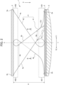
- FIG. 1 is a front view showing a non-pneumatic tire according to an exemplary embodiment of the present invention.
- FIG. 2 is a cross-sectional view taken along the line A-A in FIG. 1 .
- FIG. 3 is a cross-sectional view taken along the line B-B in FIG. 2 .
- a non-pneumatic tire 1 includes an outer annular portion 2, an inner annular portion 3 provided concentrically inside the outer annular portion 2, and a plurality of link parts 4 that each connect the outer annular portion 2 and the inner annular portion 3, and are provided independently along the tire circumferential direction D.
- the outer annular portion 2 has the outer periphery including a tread 5 provided thereon.
- the tread 5 is provided with a tread pattern similar to that of a conventional pneumatic tire.
- the outer annular portion 2 and the inner annular portion 3 will be described. It should be noted that, in the following, the thicknesses of the outer annular portion 2 and the inner annular portion 3 each refer to the plate thickness in the direction along the tire radial direction X shown in FIGS. 1 and 2 . The widths of the outer annular portion 2 and the inner annular portion 3 each refer to the width in the direction along the tire width direction Y shown in FIG. 2 .
- the outer annular portion 2 has a constant thickness in the circumferential direction and the width direction from the viewpoint of improving the uniformity.
- the thickness of the outer annular portion 2 is not particularly limited; however, from the viewpoint of reducing weight and improving durability while sufficiently transmitting the force from the link parts 4, it is preferable that the thickness of the outer annular portion 2 is 2% or more and 7% or less, and more preferably 2% or more and 5% or less, of the tire cross-sectional height H shown in FIG. 2 .
- the inner diameter of the outer annular portion 2 is appropriately determined in accordance with the application or the like.
- the inner diameter of the outer annular portion 2 may be 420 mm or more and 750 mm or less.
- the width of the outer annular portion 2 is appropriately determined in accordance with the application or the like.
- the width of the outer annular portion 2 may be 100 mm or more and 300 mm or less.
- the inner annular portion 3 has a constant thickness in the circumferential direction and the width direction from the viewpoint of improving the uniformity.
- the inner circumferential surface of the inner annular portion 3 may include irregularities or the like for retaining the fitting property for mounting with the axle and rim.
- the thickness of the inner annular portion 3 is not particularly limited; however, from the viewpoint of improving the weight reduction and durability while sufficiently transmitting a force to the link parts 4, it is preferable that the thickness of the inner annular portion 3 be 2% or more and 7% or less, and more preferably 3% or more and 6% or less, of the tire cross-sectional height H shown in FIG. 2 .
- the inner diameter of the inner annular portion 3 is appropriately determined in accordance with the dimensions and the like of the rim and the axle to which the non-pneumatic tire 1 is mounted.
- the inner diameter of the inner annular portion 3 may be 250 mm or more and 500 mm or less.
- the width of the inner annular portion 3 is appropriately determined according to the application, the length of the axle, and the like. For example, when assuming substitution of general pneumatic tires, the width of the inner annular portion 3 may be 100 mm or more and 300 mm or less.
- the link parts 4 are each a member serving as a spoke in the non-pneumatic tire 1 and connecting the outer annular portion 2 and the inner annular portion 3 so as to maintain a constant interval.
- the plurality of link parts 4 are independently arranged at regular intervals along the tire circumferential direction D. As shown in FIG. 1 , the plurality of link parts 4 extend linearly in the radial direction along the tire radial direction X when the non-pneumatic tire 1 is viewed in the unloaded state from the front direction along the tire rotation axis.
- the link part 4 is made of an elastic material.
- Elastic material refers to, for example, a material in which tensile modulus calculated from the tensile stress at 10% elongation is 100 MPa or less when subjected to a tensile test in accordance with JIS K7321. More specifically, from the viewpoint of imparting moderate stiffness while maintaining adequate durability, it is preferable that the tensile modulus is 5 MPa or more and 100 MPa or less, and more preferably 7 MPa or more and 50 MPa or less.
- Examples of the elastic material used as the base material of the link part 4 include thermoplastic elastomers, crosslinked rubbers, and other resins.
- thermoplastic elastomer examples include polyester elastomer, polyolefin elastomer, polyamide elastomer, polystyrene elastomer, polyvinyl chloride elastomer, and polyurethane elastomer.
- any natural rubber and synthetic rubber can be used.
- the synthetic rubber include styrene butadiene rubber (SBR), butadiene rubber (BR), isoprene rubber (IIR), nitrile rubber (NBR), hydrogenated nitrile rubber (hydrogenated NBR), chloroprene rubber (CR), ethylene propylene rubber (EPDM), fluororubber, silicon rubber, acrylic rubber, and urethane rubber. Two or more of these rubber materials may be used in combination if necessary.
- thermoplastic resins examples include polyethylene resins, polystyrene resins, and polyvinyl chloride resins.
- thermosetting resins include, for example, epoxy resins, phenolic resins, polyurethane resins, silicon resins, polyimide resins, and melamine resins.
- a polyurethane resin is preferably used for the link parts 4 from the viewpoint of molding, processability and cost.
- a foam material can also be used as the elastic material.
- those obtained by foaming the above-mentioned thermoplastic elastomer, crosslinked rubber, or other resins can be used.
- the link parts 4 may be formed integrally with the outer annular portion 2 and the inner annular portion 3 using the same resin material.
- the plurality of link parts 4 are configured such that a first link part 41 and a second link part 42 are alternately arranged along the tire circumferential direction D.
- the first link part 41 extends from one side Y1 in the tire width direction Y of the outer annular portion 2 toward the other side Y2 in the tire width direction Y of the inner annular portion 3.
- the second link part 42 extends from the other side Y2 in the tire width direction Y of the outer annular portion 2 toward the one side Y1 in the tire width direction Y of the inner annular portion 3.
- the first link part 41 and the second link part 42 adjacent to each other in the tire circumferential direction D are arranged so as to intersect in a substantially X-shape, when viewed in the tire circumferential direction D.
- the first link part 41 and the second link part 42 as viewed in the tire radial direction X are parallel or substantially parallel to the tire width direction Y, and extend in a direction perpendicular or substantially perpendicular to the tire equatorial plane S.
- the first link part 41 and the second link part 42 as viewed from the tire circumferential direction D have the same shape, and are symmetrical with respect to the tire equatorial plane S. Therefore, the specific shape of each link part 4 will be described using the first link part 41.
- the tire equatorial plane S refers to a plane perpendicular or substantially perpendicular to the tire rotation axis (tire meridian), and a plane located at the center in the tire width direction Y.
- the link part 4 has an elongated plate shape extending obliquely toward the inner annular portion 3 from the outer annular portion 2. As shown in FIGS. 2 and 3 , the link part 4 has a plate width W (Wr, Wt) which is smaller than the plate thickness T, and the plate thickness direction PT is along the tire circumferential direction D. That is, the link part 4 has a plate shape extending in the tire radial direction X and the tire width direction Y. It should be noted that the plate thickness T of the link part 4 refers to the thickness of the link part 4 along the tire circumferential direction D.
- the plate width W of the link part 4 refers to a width of the link part 4 in the direction along the tire width direction Y.
- the link part 4 has such an elongated plate shape that, even in a case of a thin plate thickness T, it is still possible to improve the durability of the link part 4 having the thin plate thickness T by setting a wide plate width W. Furthermore, by increasing the number of the first link parts 41 and the second link parts 42 while reducing the plate thickness T, it is possible to reduce the gap between the link parts 4 and 4 adjacent to each other in the tire circumferential direction D while maintaining the rigidity of the entire tire. This makes it possible to reduce the ground pressure dispersion while the tire is rolling. Further detailed configuration of the plate thickness T and the plate width W of the link part 4 will be described later.
- the link part 4 has a shape in which a connecting portion 401 with the outer annular portion 2 and a connecting portion 402 with the inner annular portion 3 gently spread along the tire width direction Y, respectively.
- the connecting portion 401 with the outer annular portion 2 of the first link part 41 is provided over a half area of the outer annular portion 2 in the tire width direction.
- the one side Y1 of the connecting portion 401 of the first link part 41 extends to an end portion 2a of the one side Y1 of the outer annular portion 2.
- the other side Y2 of the connecting portion 401 of the first link part 41 extends to the tire equatorial plane S disposed in the middle of the outer annular portion 2 in the tire width direction.
- the other side Y2 of the connecting portion 401 of the first link part 41 extends to an end portion 3b of the other side Y2 of the inner annular portion 3.
- the one side Y1 of the connecting portion 402 of the first link part 41 extends to the tire equatorial plane S disposed in the middle of the inner annular portion 3 in the tire width direction.
- the other side Y2 of the connecting portion 401 of the second link part 42 extends to an end portion 2b of the other side Y2 of the outer annular portion 2.
- the one side Y1 of the connecting portion 401 of the second link part 42 extends to the tire equatorial plane S disposed in the middle of the outer annular portion 2 in the tire width direction.
- the one side Y1 of the connecting portion 402 of the second link part 42 extends to an end portion 3a of the one side Y1 of the inner annular portion 3.
- the other side Y2 of the connecting portion 402 of the second link part 42 extends to the tire equatorial plane S disposed in the middle of the tire width direction of the inner annular portion 3.
- the pitch p between the first link part 41 and the second link part 42 adjacent to each other in the tire circumferential direction D is preferably constant and small in the tire circumferential direction D. More specifically, the pitch p is preferably 1 mm or more and 10 mm or less, and more preferably 1 mm or more and 5 mm or less. When the pitch p is greater than 10 mm, the ground pressure tends to become uneven in the tire circumferential direction D, and the vehicle external sound may be generated.
- the number of the link parts 4 provided in the non-pneumatic tire 1 is preferably 80 or more and 300 or less, and more preferably 100 or more and 200 or less from the viewpoint of the improvement in weight reduction, power transmission, and durability while sufficiently supporting the load from the vehicle.
- FIG. 1 shows an example in which 50 pieces of first link parts 41 and 50 pieces of second link parts 42 are provided.
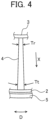
- the plate thickness T of the link part 4 differs between in the vicinity of the outer annular portion 2 and in the vicinity of the inner annular portion 3. More specifically, the plate thickness T of the link part 4 is smaller toward the inner annular portion 3 of the plate thickness Tr than the plate thickness Tt of the outer annular portion 2. Therefore, even when the plate thickness of the link part 4 becomes large as a whole, or even when increasing the number of link parts 4 along the tire circumferential direction D, it is possible to maintain the distance between the link parts 4 and 4 adjacent to each other in the tire circumferential direction D in the inner annular portion 3.
- the plate thicknesses Tt and Tr are not limited specifically; however, for example, the plate thickness Tt of the link part 4 in the vicinity of the outer annular portion 2 may be, for example, 18% or more and 22% or less of the tire cross-sectional height H, and the plate thickness Tr in the vicinity of the inner annular portion 3 of the link part 4 may be, for example, 13% or more and 17% or less of the tire cross-sectional height H.
- the plate width W of the link part 4 differs between the vicinity of the outer annular portion 2 and the vicinity of the inner annular portion 3. More specifically, in relation to the plate width W of the link part 4, the plate width Wr in the vicinity of the inner annular portion 3 is larger than the plate width Wt in the vicinity of the outer annular portion 2. Therefore, even when the plate thickness Tr in the vicinity of the inner annular portion 3 is smaller than the plate thickness Tt in the vicinity of the outer annular portion 2, it is still possible to reduce the difference in the respective cross-sectional areas when the link part 4 is cut in a plane perpendicular or substantially perpendicular to the tire radial direction X in the vicinity of the outer annular portion 2 and in the vicinity of the inner annular portion 3. This makes it possible to improve the strength of the connection sites between the inner annular portion 3 and the link part 4 in the vicinity of the inner annular portion 3 at which the plate thickness Tr becomes small, and to improve the durability of the link part 4.
- the plate width Wt in the vicinity of the outer annular portion 2 and the plate width Wr in the vicinity of the inner annular portion 3 of the link part 4 each refer to a plate width of the portion to be deflected, and refer to a plate width at a position as close as possible to the outer annular portion 2 and the inner annular portion 3 when a load is applied to the link part 4. As shown in FIG.
- the plate width Wt in the vicinity of the outer annular portion 2 of the link part 4 is located closer to the inner annular portion 3 than the connecting portion 401, and refers to a portion adjacent to the connecting portion 401. This portion is located in the vicinity of the outer annular portion 2 relative to the position which is half of the tire cross-sectional height H.
- the plate width Wr of the link part 4 in the vicinity of the inner annular portion 3 is located closer to the outer annular portion 2 than the connecting portion 402, and refers to a width of a portion adjacent to the connecting portion 402. This portion is located in the vicinity of the inner annular portion 3 relative to the position which is half of the tire cross-sectional height H.
- the plate width W of the link part 4 shown in FIG. 2 gradually increases toward the inner annular portion 3 from the outer annular portion 2. More specifically, an inner line 4a and an outer line 4b in the tire width direction Y in the link part 4 are provided so as to extend in the tire width direction Y at a constant ratio from the vicinity of the connecting portion 401 with the outer annular portion 2 toward the vicinity of the connecting portion 402 with the inner annular portion 3. With such a configuration, it is possible to make the cross-sectional area of the link part 4 substantially uniform over the entire tire cross-sectional height H.
- the inner line 4a is defined as a line making the intersection angle ⁇ 1 between the outer annular portion 2 and the inner line 4a to be an obtuse angle
- the outer line 4b is defined as a line making the intersection angle ⁇ 2 between the outer annular portion 2 and the outer line 4b to be an acute angle. Therefore, in the first link part 41 shown in FIG.
- the inner line 4a is a line of the other side Y2 in the tire width direction Y
- the outer line 4b is a line of the one side Y1 in the tire width direction Y
- the inner line 4a is a line of the one side Y1 in the tire width direction Y
- the outer line 4b is a line of the other side Y2 in the tire width direction Y.
- the plate width W of the link part 4 may gradually increase from the middle portion in the tire radial direction X in the link part 4 toward the inner annular portion 3.
- the plate width Wt in the vicinity of the outer annular portion 2 with respect to the position which is half of the tire cross-sectional height H is a constant width
- the plate width Wr in the vicinity of the inner annular portion 3 with respect to the position which is half of the tire cross-sectional height H increases toward the inner annular portion 3 with respect to the position which is half of the tire cross-sectional height H.
- the plate width W of the link part 4 may gradually increase from the vicinity of the outer annular portion 2 toward the vicinity of the inner annular portion 3.
- the plate width Wr of the link part 4 in the vicinity of the inner annular portion 3 increases stepwise.
- the outer line 4b may also be formed in a stepped manner.
- the plate width W of the link part 4 may increase in a stepwise manner by forming the inner line 4a and the outer line 4b of the link part 4 in a stepwise manner over the entire tire cross-sectional height H.
- the method of increasing the plate width Wr of the link part 4 in the vicinity of the inner annular portion 3 is not limited to those for changing the angle and shape of both the inner line 4a and the outer line 4b of the link part 4, and may change the angle and shape of only one of the inner line 4a and the outer line 4b.
- the plate width Wr of the link part 4 in the vicinity of the inner annular portion 3 is formed larger.
- the plate width Wr of the link part 4 in the vicinity of the inner annular portion 3 may be formed to be large without changing the shape of the inner line 4a of the link part 4.
Landscapes
- Engineering & Computer Science (AREA)
- Mechanical Engineering (AREA)
- Tires In General (AREA)
Description
- The present invention relates to a non-pneumatic tire.
- In recent years, a non-pneumatic tire has been known for which the occurrence of punctures, etc. is not a problem (refer to, for example,
Japanese Unexamined Patent Application, Publication No. 2017-218132
Patent Document 1:Japanese Unexamined Patent Application, Publication No. 2017-218132 - Document
US 2019/184748 A1 describes a non-pneumatic tire including an inner annular portion, an outer annular portion, and a plurality of connecting portions connecting the inner and outer annular portions to each other. The first and second connecting portions are arrayed along a tire circumferential direction. The first and second connecting portions have a plate thickness smaller than a plate width and have a plate thickness direction oriented to the tire circumferential direction. When "S" is a length in the tire width direction and "H" is a height in a tire radial direction in the first and second connecting portions, an inclination angle "K" of a centerline of each plate width of the first and second connecting portions to the tire width direction in intersecting portions of the first and second connecting portions when viewed from the tire circumferential direction satisfies a relationship of 30×(H/S)0.7 ≤ K ≤ 75×(H/S)0.7. - Document
US 2019/070904 A1 describes a non-pneumatic tire including a support structure for supporting a load from a vehicle. The support structure includes an inner annular portion, an outer annular portion concentrically provided on an outer side of the inner annular portion, and a plurality of connecting portions which connect the inner annular portion and the outer annular portion to each other and are provided in a tire circumferential direction independently of one another, the plurality of connecting portions are configured such that elongated plate-like first connecting portions and elongated plate-like second connecting portions are arrayed along the tire circumferential direction, a plate thickness is smaller than a plate width, a plate thickness direction is oriented to the tire circumferential direction, and a plate thickness at a tire radial direction inner end coupled to the inner annular portion is larger than a plate thickness at a tire radial direction center portion. - Document
US 2019/070905 A1 describes a non-pneumatic tire including a support structure for supporting a load from a vehicle. The support structure includes an inner annular portion, an outer annular portion concentrically provided outside the inner annular portion, and a plurality of connecting portions which connect the inner annular portion and the outer annular portion to each other and are provided in a tire circumferential direction independently of one another, and the plurality of connecting portions are configured such that elongated plate-like first connecting portions and elongated plate-like second connecting portions are arrayed along the tire circumferential direction, the first connecting portions being extended from one side in a tire width direction of the inner annular portion to other side in a tire width direction of the outer annular portion, and the second connecting portions being extended from other side. - Document
US 2019/070902 A1 describes a non-pneumatic tire wherein, at least one of a first connecting portions extends in such fashion as to be directed from one side in a tire width direction of an inner annular portion to the other side in a tire width direction of an outer annular portion, at least one of a second connecting portions extends in such fashion as to be directed from the other side in the tire width direction of the inner annular portion to the one side in the tire width direction of the outer annular portion, such that, the at least one second connecting portion appears to intersect the at least one first connecting portion, and that a maximum dimension in a tire radial direction of at least one of the closed spaces is greater than or equal to a maximum dimension in the tire width direction of the at least one closed space. - Document
US 2019/070903 A1 describes a non-pneumatic tire including a support structure for supporting a load from a vehicle. The support structure includes an inner annular portion, an outer annular portion concentrically provided on an outer side of the inner annular portion, and a plurality of connecting portions which connect the inner annular portion and the outer annular portion to each other and are provided in a tire circumferential direction independently of one another, the plurality of connecting portions are configured such that elongated plate-like first connecting portions and elongated plate-like second connecting portions are arrayed along the tire circumferential direction, an angle α and an angle β, the angles being formed by an inner circumferential surface of the outer annular portion and both side surfaces of each of the connecting portions, both surfaces facing the tire circumferential direction, are 75° or more and 120° or less. - In such a non-pneumatic tire, the distance between link parts adjacent to each other in the tire circumferential direction is larger at the outer annular side and smaller at the inner annular side due to the circumferential length difference between the outer annular portion and the inner annular portion. Therefore, as the number of link parts increases, it becomes difficult to maintain the distance between adjacent link parts. On the other hand, when the link parts along the tire circumferential direction are made thinner on the inner annular portion side than on the outer annular portion side in order to maintain the distance between the adjacent link parts, the strength of the link parts differs between the connection sites with the outer annular portion and the connection sites with the inner annular portion, such that the durability of the link parts is lowered, and the link parts may break when the repeated stress while the tire is rolling is applied to the link parts. Therefore, conventional non-pneumatic tires address improving the strength of the connection sites between the inner annular portion and the link parts and improving the durability of the link parts while maintaining the distance between the adjacent link parts on the inner annular portion side.
- The present invention has been made in view of the above problems, and an object thereof is to provide a non-pneumatic tire capable of improving the strength of connection sites between an inner annular portion and link parts, while maintaining a distance between adjacent link parts on an inner annular portion side, and improving the durability of the link parts.
- The claimed invention is defined by the features set forth in the appended independent claim. Additional embodiments of the claimed invention are defined by the dependent claims.
- According to an exemplary embodiment of the present invention, it is possible to provide a non-pneumatic tire capable of improving the strength of connection sites between an inner annular portion and link parts while maintaining a distance between adjacent link parts on an inner annular portion side, and improving the durability of the link parts.
-
-
FIG. 1 is a front view showing a non-pneumatic tire according to an exemplary embodiment of the present invention. -
FIG. 2 is a cross-sectional view taken along the line A-A inFIG. 1 . The embodiment ofFIG. 2 is not encompassed by the wording of the claims but is considered as useful for understanding the invention. -
FIG. 3 is a cross-sectional view taken along the line B-B inFIG. 2 . -
FIG. 4 is a diagram for explaining the thickness of a link part along a tire circumferential direction. -
FIG. 5 is a cross-sectional view showing a link part of a non-pneumatic tire according to another exemplary embodiment of the present invention. -
FIG. 6 is a cross-sectional view showing a link part of a non-pneumatic tire according to yet another exemplary embodiment of the present invention. - Exemplary embodiments of the present invention will be described below with reference to the drawings.
FIG. 1 is a front view showing a non-pneumatic tire according to an exemplary embodiment of the present invention.FIG. 2 is a cross-sectional view taken along the line A-A inFIG. 1 .FIG. 3 is a cross-sectional view taken along the line B-B inFIG. 2 . Anon-pneumatic tire 1 includes an outerannular portion 2, an innerannular portion 3 provided concentrically inside the outerannular portion 2, and a plurality oflink parts 4 that each connect the outerannular portion 2 and the innerannular portion 3, and are provided independently along the tire circumferential direction D. The outerannular portion 2 has the outer periphery including atread 5 provided thereon. Thetread 5 is provided with a tread pattern similar to that of a conventional pneumatic tire. - First, the outer
annular portion 2 and the innerannular portion 3 will be described. It should be noted that, in the following, the thicknesses of the outerannular portion 2 and the innerannular portion 3 each refer to the plate thickness in the direction along the tire radial direction X shown inFIGS. 1 and2 . The widths of the outerannular portion 2 and the innerannular portion 3 each refer to the width in the direction along the tire width direction Y shown inFIG. 2 . - The outer
annular portion 2 has a constant thickness in the circumferential direction and the width direction from the viewpoint of improving the uniformity. The thickness of the outerannular portion 2 is not particularly limited; however, from the viewpoint of reducing weight and improving durability while sufficiently transmitting the force from thelink parts 4, it is preferable that the thickness of the outerannular portion 2 is 2% or more and 7% or less, and more preferably 2% or more and 5% or less, of the tire cross-sectional height H shown inFIG. 2 . - The inner diameter of the outer
annular portion 2 is appropriately determined in accordance with the application or the like. For example, when assuming substitution of general pneumatic tires, the inner diameter of the outerannular portion 2 may be 420 mm or more and 750 mm or less. - The width of the outer
annular portion 2 is appropriately determined in accordance with the application or the like. For example, when assuming substitution of general pneumatic tires, the width of the outerannular portion 2 may be 100 mm or more and 300 mm or less. - The inner
annular portion 3 has a constant thickness in the circumferential direction and the width direction from the viewpoint of improving the uniformity. Although not shown, the inner circumferential surface of the innerannular portion 3 may include irregularities or the like for retaining the fitting property for mounting with the axle and rim. The thickness of the innerannular portion 3 is not particularly limited; however, from the viewpoint of improving the weight reduction and durability while sufficiently transmitting a force to thelink parts 4, it is preferable that the thickness of the innerannular portion 3 be 2% or more and 7% or less, and more preferably 3% or more and 6% or less, of the tire cross-sectional height H shown inFIG. 2 . - The inner diameter of the inner
annular portion 3 is appropriately determined in accordance with the dimensions and the like of the rim and the axle to which thenon-pneumatic tire 1 is mounted. For example, when assuming the substitution of general pneumatic tires, the inner diameter of the innerannular portion 3 may be 250 mm or more and 500 mm or less. - The width of the inner
annular portion 3 is appropriately determined according to the application, the length of the axle, and the like. For example, when assuming substitution of general pneumatic tires, the width of the innerannular portion 3 may be 100 mm or more and 300 mm or less. - The
link parts 4 are each a member serving as a spoke in thenon-pneumatic tire 1 and connecting the outerannular portion 2 and the innerannular portion 3 so as to maintain a constant interval. The plurality oflink parts 4 are independently arranged at regular intervals along the tire circumferential direction D. As shown inFIG. 1 , the plurality oflink parts 4 extend linearly in the radial direction along the tire radial direction X when thenon-pneumatic tire 1 is viewed in the unloaded state from the front direction along the tire rotation axis. - The
link part 4 is made of an elastic material. Elastic material refers to, for example, a material in which tensile modulus calculated from the tensile stress at 10% elongation is 100 MPa or less when subjected to a tensile test in accordance with JIS K7321. More specifically, from the viewpoint of imparting moderate stiffness while maintaining adequate durability, it is preferable that the tensile modulus is 5 MPa or more and 100 MPa or less, and more preferably 7 MPa or more and 50 MPa or less. - Examples of the elastic material used as the base material of the
link part 4 include thermoplastic elastomers, crosslinked rubbers, and other resins. - Examples of the thermoplastic elastomer include polyester elastomer, polyolefin elastomer, polyamide elastomer, polystyrene elastomer, polyvinyl chloride elastomer, and polyurethane elastomer.
- As the rubber material constituting the crosslinked rubber, any natural rubber and synthetic rubber can be used. Examples of the synthetic rubber include styrene butadiene rubber (SBR), butadiene rubber (BR), isoprene rubber (IIR), nitrile rubber (NBR), hydrogenated nitrile rubber (hydrogenated NBR), chloroprene rubber (CR), ethylene propylene rubber (EPDM), fluororubber, silicon rubber, acrylic rubber, and urethane rubber. Two or more of these rubber materials may be used in combination if necessary.
- Examples of other resins include thermoplastic resins and thermosetting resins. Examples of the thermoplastic resin include polyethylene resins, polystyrene resins, and polyvinyl chloride resins. The thermosetting resins include, for example, epoxy resins, phenolic resins, polyurethane resins, silicon resins, polyimide resins, and melamine resins.
- Among the above-mentioned elastic materials, a polyurethane resin is preferably used for the
link parts 4 from the viewpoint of molding, processability and cost. It should be noted that a foam material can also be used as the elastic material. In other words, those obtained by foaming the above-mentioned thermoplastic elastomer, crosslinked rubber, or other resins can be used. Furthermore, when the outerannular portion 2 and the innerannular portion 3 are made of resin, thelink parts 4 may be formed integrally with the outerannular portion 2 and the innerannular portion 3 using the same resin material. - The plurality of
link parts 4 are configured such that afirst link part 41 and asecond link part 42 are alternately arranged along the tire circumferential direction D. As shown inFIG. 2 , thefirst link part 41 extends from one side Y1 in the tire width direction Y of the outerannular portion 2 toward the other side Y2 in the tire width direction Y of the innerannular portion 3. Thesecond link part 42 extends from the other side Y2 in the tire width direction Y of the outerannular portion 2 toward the one side Y1 in the tire width direction Y of the innerannular portion 3. Thefirst link part 41 and thesecond link part 42 adjacent to each other in the tire circumferential direction D are arranged so as to intersect in a substantially X-shape, when viewed in the tire circumferential direction D. Thefirst link part 41 and thesecond link part 42 as viewed in the tire radial direction X are parallel or substantially parallel to the tire width direction Y, and extend in a direction perpendicular or substantially perpendicular to the tire equatorial plane S. - As shown in
FIG. 2 , thefirst link part 41 and thesecond link part 42 as viewed from the tire circumferential direction D have the same shape, and are symmetrical with respect to the tire equatorial plane S. Therefore, the specific shape of eachlink part 4 will be described using thefirst link part 41. It should be noted that the tire equatorial plane S refers to a plane perpendicular or substantially perpendicular to the tire rotation axis (tire meridian), and a plane located at the center in the tire width direction Y. - The
link part 4 has an elongated plate shape extending obliquely toward the innerannular portion 3 from the outerannular portion 2. As shown inFIGS. 2 and3 , thelink part 4 has a plate width W (Wr, Wt) which is smaller than the plate thickness T, and the plate thickness direction PT is along the tire circumferential direction D. That is, thelink part 4 has a plate shape extending in the tire radial direction X and the tire width direction Y. It should be noted that the plate thickness T of thelink part 4 refers to the thickness of thelink part 4 along the tire circumferential direction D. The plate width W of thelink part 4 refers to a width of thelink part 4 in the direction along the tire width direction Y. Thelink part 4 has such an elongated plate shape that, even in a case of a thin plate thickness T, it is still possible to improve the durability of thelink part 4 having the thin plate thickness T by setting a wide plate width W. Furthermore, by increasing the number of thefirst link parts 41 and thesecond link parts 42 while reducing the plate thickness T, it is possible to reduce the gap between thelink parts link part 4 will be described later. - As shown in
FIG. 2 , thelink part 4 has a shape in which a connectingportion 401 with the outerannular portion 2 and a connectingportion 402 with the innerannular portion 3 gently spread along the tire width direction Y, respectively. The connectingportion 401 with the outerannular portion 2 of thefirst link part 41 is provided over a half area of the outerannular portion 2 in the tire width direction. - That is, the one side Y1 of the connecting
portion 401 of thefirst link part 41 extends to anend portion 2a of the one side Y1 of the outerannular portion 2. The other side Y2 of the connectingportion 401 of thefirst link part 41 extends to the tire equatorial plane S disposed in the middle of the outerannular portion 2 in the tire width direction. The other side Y2 of the connectingportion 401 of thefirst link part 41 extends to anend portion 3b of the other side Y2 of the innerannular portion 3. The one side Y1 of the connectingportion 402 of thefirst link part 41 extends to the tire equatorial plane S disposed in the middle of the innerannular portion 3 in the tire width direction. - Similarly, the other side Y2 of the connecting
portion 401 of thesecond link part 42 extends to anend portion 2b of the other side Y2 of the outerannular portion 2. The one side Y1 of the connectingportion 401 of thesecond link part 42 extends to the tire equatorial plane S disposed in the middle of the outerannular portion 2 in the tire width direction. The one side Y1 of the connectingportion 402 of thesecond link part 42 extends to anend portion 3a of the one side Y1 of the innerannular portion 3. The other side Y2 of the connectingportion 402 of thesecond link part 42 extends to the tire equatorial plane S disposed in the middle of the tire width direction of the innerannular portion 3. - The pitch p between the
first link part 41 and thesecond link part 42 adjacent to each other in the tire circumferential direction D is preferably constant and small in the tire circumferential direction D. More specifically, the pitch p is preferably 1 mm or more and 10 mm or less, and more preferably 1 mm or more and 5 mm or less. When the pitch p is greater than 10 mm, the ground pressure tends to become uneven in the tire circumferential direction D, and the vehicle external sound may be generated. - The number of the
link parts 4 provided in thenon-pneumatic tire 1 is preferably 80 or more and 300 or less, and more preferably 100 or more and 200 or less from the viewpoint of the improvement in weight reduction, power transmission, and durability while sufficiently supporting the load from the vehicle.FIG. 1 shows an example in which 50 pieces offirst link parts 41 and 50 pieces ofsecond link parts 42 are provided. - As shown in
FIG. 4 , the plate thickness T of thelink part 4 differs between in the vicinity of the outerannular portion 2 and in the vicinity of the innerannular portion 3. More specifically, the plate thickness T of thelink part 4 is smaller toward the innerannular portion 3 of the plate thickness Tr than the plate thickness Tt of the outerannular portion 2. Therefore, even when the plate thickness of thelink part 4 becomes large as a whole, or even when increasing the number oflink parts 4 along the tire circumferential direction D, it is possible to maintain the distance between thelink parts annular portion 3. The plate thicknesses Tt and Tr are not limited specifically; however, for example, the plate thickness Tt of thelink part 4 in the vicinity of the outerannular portion 2 may be, for example, 18% or more and 22% or less of the tire cross-sectional height H, and the plate thickness Tr in the vicinity of the innerannular portion 3 of thelink part 4 may be, for example, 13% or more and 17% or less of the tire cross-sectional height H. - As shown in
FIG. 2 , the plate width W of thelink part 4 differs between the vicinity of the outerannular portion 2 and the vicinity of the innerannular portion 3. More specifically, in relation to the plate width W of thelink part 4, the plate width Wr in the vicinity of the innerannular portion 3 is larger than the plate width Wt in the vicinity of the outerannular portion 2. Therefore, even when the plate thickness Tr in the vicinity of the innerannular portion 3 is smaller than the plate thickness Tt in the vicinity of the outerannular portion 2, it is still possible to reduce the difference in the respective cross-sectional areas when thelink part 4 is cut in a plane perpendicular or substantially perpendicular to the tire radial direction X in the vicinity of the outerannular portion 2 and in the vicinity of the innerannular portion 3. This makes it possible to improve the strength of the connection sites between the innerannular portion 3 and thelink part 4 in the vicinity of the innerannular portion 3 at which the plate thickness Tr becomes small, and to improve the durability of thelink part 4. - It should be noted that the plate width Wt in the vicinity of the outer
annular portion 2 and the plate width Wr in the vicinity of the innerannular portion 3 of thelink part 4 each refer to a plate width of the portion to be deflected, and refer to a plate width at a position as close as possible to the outerannular portion 2 and the innerannular portion 3 when a load is applied to thelink part 4. As shown inFIG. 2 , when the connectingportion 401 between thelink part 4 and the outerannular portion 2, and the connectingportion 402 between thelink part 4 and the innerannular portion 3 each have a shape extending in the tire width direction Y, the plate width Wt in the vicinity of the outerannular portion 2 of thelink part 4 is located closer to the innerannular portion 3 than the connectingportion 401, and refers to a portion adjacent to the connectingportion 401. This portion is located in the vicinity of the outerannular portion 2 relative to the position which is half of the tire cross-sectional height H. Furthermore, the plate width Wr of thelink part 4 in the vicinity of the innerannular portion 3 is located closer to the outerannular portion 2 than the connectingportion 402, and refers to a width of a portion adjacent to the connectingportion 402. This portion is located in the vicinity of the innerannular portion 3 relative to the position which is half of the tire cross-sectional height H. - The plate width W of the
link part 4 shown inFIG. 2 gradually increases toward the innerannular portion 3 from the outerannular portion 2. More specifically, aninner line 4a and anouter line 4b in the tire width direction Y in thelink part 4 are provided so as to extend in the tire width direction Y at a constant ratio from the vicinity of the connectingportion 401 with the outerannular portion 2 toward the vicinity of the connectingportion 402 with the innerannular portion 3. With such a configuration, it is possible to make the cross-sectional area of thelink part 4 substantially uniform over the entire tire cross-sectional height H. - It should be noted that, when viewing the
link part 4 extending obliquely from the outerannular portion 2 toward the innerannular portion 3 in the tire circumferential direction D, as shown inFIG. 2 , theinner line 4a is defined as a line making the intersection angle θ1 between the outerannular portion 2 and theinner line 4a to be an obtuse angle, and theouter line 4b is defined as a line making the intersection angle θ2 between the outerannular portion 2 and theouter line 4b to be an acute angle. Therefore, in thefirst link part 41 shown inFIG. 2 , theinner line 4a is a line of the other side Y2 in the tire width direction Y, and theouter line 4b is a line of the one side Y1 in the tire width direction Y. In thesecond link part 42, theinner line 4a is a line of the one side Y1 in the tire width direction Y, and theouter line 4b is a line of the other side Y2 in the tire width direction Y. - As shown in
FIG. 5 , the plate width W of thelink part 4 may gradually increase from the middle portion in the tire radial direction X in thelink part 4 toward the innerannular portion 3. In thelink part 4 shown inFIG. 5 , while the plate width Wt in the vicinity of the outerannular portion 2 with respect to the position which is half of the tire cross-sectional height H is a constant width, the plate width Wr in the vicinity of the innerannular portion 3 with respect to the position which is half of the tire cross-sectional height H increases toward the innerannular portion 3 with respect to the position which is half of the tire cross-sectional height H. With such a configuration, it is possible to prevent breakage of thelink part 4 in the vicinity of the innerannular portion 3 without impairing the ease of deformation of thelink part 4 in the vicinity of the outerannular portion 2. - As shown in
FIG. 6 , the plate width W of thelink part 4 may gradually increase from the vicinity of the outerannular portion 2 toward the vicinity of the innerannular portion 3. In thelink part 4 shown inFIG. 6 , by only theinner line 4a in the vicinity of the innerannular portion 3 being formed in a stepped shape with respect to the position which is half of the tire cross-sectional height H, the plate width Wr of thelink part 4 in the vicinity of the innerannular portion 3 increases stepwise. However, theouter line 4b may also be formed in a stepped manner. In addition, the plate width W of thelink part 4 may increase in a stepwise manner by forming theinner line 4a and theouter line 4b of thelink part 4 in a stepwise manner over the entire tire cross-sectional height H. - It should be noted that the method of increasing the plate width Wr of the
link part 4 in the vicinity of the innerannular portion 3 is not limited to those for changing the angle and shape of both theinner line 4a and theouter line 4b of thelink part 4, and may change the angle and shape of only one of theinner line 4a and theouter line 4b. For example, inFIG. 6 , by theinner line 4a being formed in a stepped shape without changing the shape of theouter line 4b of thelink part 4, the plate width Wr of thelink part 4 in the vicinity of the innerannular portion 3 is formed larger. On the contrary, the plate width Wr of thelink part 4 in the vicinity of the innerannular portion 3 may be formed to be large without changing the shape of theinner line 4a of thelink part 4. - According to the
non-pneumatic tire 1 of the present exemplary embodiments, the following advantageous effects are obtained. - According to the non-pneumatic tire as set forth in the appended independent claim, it is possible to maintain the distance between the
link parts annular portion 3 in the tire circumferential direction D, even when the plate thickness T of thelink part 4 increases as a whole, or the number oflink parts 4 along the tire circumferential direction D increases. Furthermore, even when the plate thickness Tr in the vicinity of the innerannular portion 3 is smaller than the plate thickness Tt in the vicinity of the outerannular portion 2, it is still possible to reduce the difference in the respective cross-sectional areas when thelink part 4 is cut in a plane perpendicular or substantially perpendicular to the tire radial direction X in the vicinity of the outerannular portion 2 and in the vicinity of the innerannular portion 3. This makes it possible to improve the strength of the connection sites between the innerannular portion 3 and thelink part 4 at which the plate thickness Tr becomes small, and to improve the durability of thelink part 4. - (3) With a non-pneumatic tire further comprising the additional features of
claim 2 it is possible to prevent breakage of thelink parts 4 in the vicinity of the innerannular portion 3 without impairing the ease of deformation of thelink parts 4 in the vicinity of the outerannular portion 2. -
- 1 non-pneumatic tire
- 2 outer annular portion
- 3 inner annular portion
- 4 link part
- 41 first link part
- 42 second link part
- 5 tread
- D tire circumferential direction
- T plate thickness
- Tt plate thickness in the vicinity of outer annular portion
- Tr plate thickness in the vicinity of inner annular portion
- W plate width
- Wt plate width in the vicinity of outer annular portion
- Wr plate width in the vicinity of inner annular portion
- X tire radial direction
- Y tire width direction
- Y1 one side
- Y2 other side
Claims (2)
- A non-pneumatic tire (1) comprising:an outer annular portion (2) having an outer periphery including a tread (5) provided thereon;an inner annular portion (3) provided inside the outer annular portion (2); anda plurality of link parts (4) that each connect the outer annular portion (2) and the inner annular portion (3), and are provided along a tire circumferential direction (D),wherein the plurality of link parts (4) include first link parts (41) and second link parts (42) that are alternately provided along the tire circumferential direction (D), the first link parts (41) each extending from one side (Y1) in a tire width direction (Y) of the outer annular portion (2) toward one other side (Y2) in the tire width direction (Y) of the inner annular portion (3), the second link parts (42) each extending from the other side (Y2) in the tire width direction (Y) of the outer annular portion (2) toward the one side (Y1) in the tire width direction (Y) of the inner annular portion (3),wherein the plurality of link parts (4) each have a thickness (T) in the tire circumferential direction (D) which decreases continuously from the outer annular portion (2) toward the inner annular portion (3),wherein the plurality of link parts (4) each have a first connecting portion (401) with the outer annular portion (2) and a second connecting portion (402) with the inner annular portion (3),wherein in the second connecting portion (402) the width of each link part (4) decreases from a contact end of each of the link parts (4) with the inner annular portion (3) to a radial outer end of the second connecting portion (402),wherein in the first connecting portion (401) the width of each link part (4) decreases from a contact end of each of the link parts (4) with the outer annular portion (2) to a radial inner end of the first connecting portion (401),wherein the width (Wt) of each of the plurality of link parts (4) is constant from a position which is half of the tire cross-sectional height (H) up to the radial inner end of the first connecting portion (401),characterized in thata width (Wr) of each of the plurality of link parts (4) increases from a position which is half of the tire cross-sectional height (H) up to the radial outer end of the second connecting portion (402).
- The non-pneumatic tire (1) according to claim 1, wherein the width (Wr) of each of the plurality of link parts (4) increases gradually or in a stepwise manner from the position which is half of the tire cross-sectional height (H) up to the radial outer end of the second connecting portion (402).
Applications Claiming Priority (1)
| Application Number | Priority Date | Filing Date | Title |
|---|---|---|---|
| JP2020219328A JP7712762B2 (en) | 2020-12-28 | 2020-12-28 | Non-pneumatic tires |
Publications (2)
| Publication Number | Publication Date |
|---|---|
| EP4019277A1 EP4019277A1 (en) | 2022-06-29 |
| EP4019277B1 true EP4019277B1 (en) | 2023-11-08 |
Family
ID=78916657
Family Applications (1)
| Application Number | Title | Priority Date | Filing Date |
|---|---|---|---|
| EP21214650.0A Active EP4019277B1 (en) | 2020-12-28 | 2021-12-15 | Non-pneumatic tire |
Country Status (4)
| Country | Link |
|---|---|
| US (1) | US20220203766A1 (en) |
| EP (1) | EP4019277B1 (en) |
| JP (1) | JP7712762B2 (en) |
| CN (1) | CN114683771B (en) |
Families Citing this family (2)
| Publication number | Priority date | Publication date | Assignee | Title |
|---|---|---|---|---|
| EP4393721B1 (en) * | 2022-12-26 | 2025-04-02 | Toyo Tire Corporation | Non-pneumatic tire |
| US20250319723A1 (en) * | 2024-04-15 | 2025-10-16 | Triangle Tyre Co. Ltd. | Non-Pneumatic Tire |
Family Cites Families (19)
| Publication number | Priority date | Publication date | Assignee | Title |
|---|---|---|---|---|
| US8631844B2 (en) * | 2005-06-13 | 2014-01-21 | Millenworks | Variable compliance wheel |
| JP4674253B2 (en) * | 2008-11-28 | 2011-04-20 | 東洋ゴム工業株式会社 | Non-pneumatic tire |
| JP5624736B2 (en) * | 2009-07-22 | 2014-11-12 | 株式会社ブリヂストン | Non pneumatic tire |
| JP6025498B2 (en) * | 2012-10-18 | 2016-11-16 | 東洋ゴム工業株式会社 | Non-pneumatic tire |
| JP6092046B2 (en) * | 2013-08-22 | 2017-03-08 | 東洋ゴム工業株式会社 | Non-pneumatic tire |
| JP6358733B2 (en) * | 2013-10-10 | 2018-07-18 | 株式会社ブリヂストン | Non pneumatic tire |
| JP6159234B2 (en) * | 2013-11-25 | 2017-07-05 | 東洋ゴム工業株式会社 | Non-pneumatic tire |
| JP6383294B2 (en) * | 2015-01-13 | 2018-08-29 | 住友ゴム工業株式会社 | Airless tire |
| JP6529833B2 (en) * | 2015-06-16 | 2019-06-12 | Toyo Tire株式会社 | Non pneumatic tire |
| JP6529834B2 (en) * | 2015-06-17 | 2019-06-12 | Toyo Tire株式会社 | Non pneumatic tire |
| JP6701997B2 (en) | 2016-06-10 | 2020-05-27 | 住友ゴム工業株式会社 | Non-pneumatic tire |
| JP6926820B2 (en) * | 2017-08-24 | 2021-08-25 | セイコーエプソン株式会社 | 3D modeling device and 3D modeling method |
| JP6981102B2 (en) * | 2017-08-24 | 2021-12-15 | 住友ゴム工業株式会社 | Airless tire |
| JP2019043503A (en) * | 2017-09-07 | 2019-03-22 | Toyo Tire株式会社 | Non pneumatic tire |
| JP2019043505A (en) * | 2017-09-07 | 2019-03-22 | Toyo Tire株式会社 | Non pneumatic tire |
| JP6964471B2 (en) * | 2017-09-07 | 2021-11-10 | Toyo Tire株式会社 | Non-pneumatic tire |
| JP6964470B2 (en) * | 2017-09-07 | 2021-11-10 | Toyo Tire株式会社 | Non-pneumatic tire |
| JP7004562B2 (en) * | 2017-12-14 | 2022-02-10 | Toyo Tire株式会社 | Non-pneumatic tires |
| JP7180427B2 (en) * | 2019-02-06 | 2022-11-30 | 住友ゴム工業株式会社 | airless tire |
-
2020
- 2020-12-28 JP JP2020219328A patent/JP7712762B2/en active Active
-
2021
- 2021-12-15 US US17/551,891 patent/US20220203766A1/en not_active Abandoned
- 2021-12-15 EP EP21214650.0A patent/EP4019277B1/en active Active
- 2021-12-22 CN CN202111579430.XA patent/CN114683771B/en active Active
Also Published As
| Publication number | Publication date |
|---|---|
| JP2022104243A (en) | 2022-07-08 |
| JP7712762B2 (en) | 2025-07-24 |
| CN114683771A (en) | 2022-07-01 |
| US20220203766A1 (en) | 2022-06-30 |
| CN114683771B (en) | 2025-01-07 |
| EP4019277A1 (en) | 2022-06-29 |
Similar Documents
| Publication | Publication Date | Title |
|---|---|---|
| JP4674253B2 (en) | Non-pneumatic tire | |
| EP4019277B1 (en) | Non-pneumatic tire | |
| JP2010126070A (en) | Non-pneumatic tire | |
| JP6964471B2 (en) | Non-pneumatic tire | |
| JP2019043505A (en) | Non pneumatic tire | |
| JP2019104438A (en) | Non-pneumatic tire | |
| EP3789210B1 (en) | Non-pneumatic tire | |
| EP4046821B1 (en) | Airless tire | |
| EP4019278B1 (en) | Non-pneumatic tire | |
| JP7561026B2 (en) | NON-PNEUMATIC TIRE AND METHOD FOR MANUFACTURING NON-PNEUMATIC TIRE | |
| EP4393721B1 (en) | Non-pneumatic tire | |
| JP7603444B2 (en) | Non-pneumatic tires | |
| EP4046823B1 (en) | Airless tire | |
| EP4046822B1 (en) | Airless tire | |
| JP7842552B2 (en) | Non-pneumatic tires | |
| JP7603445B2 (en) | Non-pneumatic tires | |
| JP7780313B2 (en) | Non-pneumatic tires | |
| JP2023094277A (en) | non-pneumatic tires | |
| JP2024092304A (en) | Non-pneumatic tires | |
| JP2024110133A (en) | Non-pneumatic tires | |
| JP2024162731A (en) | Non-pneumatic tires | |
| JP2024110132A (en) | Non-pneumatic tires | |
| JP2023084406A (en) | non-pneumatic tires | |
| JP2023079445A (en) | non-pneumatic tires | |
| JP2023085966A (en) | Non-pneumatic tire |
Legal Events
| Date | Code | Title | Description |
|---|---|---|---|
| PUAI | Public reference made under article 153(3) epc to a published international application that has entered the european phase |
Free format text: ORIGINAL CODE: 0009012 |
|
| STAA | Information on the status of an ep patent application or granted ep patent |
Free format text: STATUS: REQUEST FOR EXAMINATION WAS MADE |
|
| 17P | Request for examination filed |
Effective date: 20211216 |
|
| AK | Designated contracting states |
Kind code of ref document: A1 Designated state(s): AL AT BE BG CH CY CZ DE DK EE ES FI FR GB GR HR HU IE IS IT LI LT LU LV MC MK MT NL NO PL PT RO RS SE SI SK SM TR |
|
| STAA | Information on the status of an ep patent application or granted ep patent |
Free format text: STATUS: EXAMINATION IS IN PROGRESS |
|
| 17Q | First examination report despatched |
Effective date: 20230221 |
|
| GRAP | Despatch of communication of intention to grant a patent |
Free format text: ORIGINAL CODE: EPIDOSNIGR1 |
|
| STAA | Information on the status of an ep patent application or granted ep patent |
Free format text: STATUS: GRANT OF PATENT IS INTENDED |
|
| INTG | Intention to grant announced |
Effective date: 20230728 |
|
| GRAS | Grant fee paid |
Free format text: ORIGINAL CODE: EPIDOSNIGR3 |
|
| GRAA | (expected) grant |
Free format text: ORIGINAL CODE: 0009210 |
|
| STAA | Information on the status of an ep patent application or granted ep patent |
Free format text: STATUS: THE PATENT HAS BEEN GRANTED |
|
| AK | Designated contracting states |
Kind code of ref document: B1 Designated state(s): AL AT BE BG CH CY CZ DE DK EE ES FI FR GB GR HR HU IE IS IT LI LT LU LV MC MK MT NL NO PL PT RO RS SE SI SK SM TR |
|
| REG | Reference to a national code |
Ref country code: GB Ref legal event code: FG4D |
|
| REG | Reference to a national code |
Ref country code: CH Ref legal event code: EP |
|
| REG | Reference to a national code |
Ref country code: DE Ref legal event code: R096 Ref document number: 602021006642 Country of ref document: DE |
|
| REG | Reference to a national code |
Ref country code: IE Ref legal event code: FG4D |
|
| REG | Reference to a national code |
Ref country code: LT Ref legal event code: MG9D |
|
| REG | Reference to a national code |
Ref country code: NL Ref legal event code: MP Effective date: 20231108 |
|
| PG25 | Lapsed in a contracting state [announced via postgrant information from national office to epo] |
Ref country code: GR Free format text: LAPSE BECAUSE OF FAILURE TO SUBMIT A TRANSLATION OF THE DESCRIPTION OR TO PAY THE FEE WITHIN THE PRESCRIBED TIME-LIMIT Effective date: 20240209 |
|
| PG25 | Lapsed in a contracting state [announced via postgrant information from national office to epo] |
Ref country code: IS Free format text: LAPSE BECAUSE OF FAILURE TO SUBMIT A TRANSLATION OF THE DESCRIPTION OR TO PAY THE FEE WITHIN THE PRESCRIBED TIME-LIMIT Effective date: 20240308 |
|
| PG25 | Lapsed in a contracting state [announced via postgrant information from national office to epo] |
Ref country code: LT Free format text: LAPSE BECAUSE OF FAILURE TO SUBMIT A TRANSLATION OF THE DESCRIPTION OR TO PAY THE FEE WITHIN THE PRESCRIBED TIME-LIMIT Effective date: 20231108 |
|
| REG | Reference to a national code |
Ref country code: AT Ref legal event code: MK05 Ref document number: 1629313 Country of ref document: AT Kind code of ref document: T Effective date: 20231108 |
|
| PG25 | Lapsed in a contracting state [announced via postgrant information from national office to epo] |
Ref country code: NL Free format text: LAPSE BECAUSE OF FAILURE TO SUBMIT A TRANSLATION OF THE DESCRIPTION OR TO PAY THE FEE WITHIN THE PRESCRIBED TIME-LIMIT Effective date: 20231108 |
|
| PG25 | Lapsed in a contracting state [announced via postgrant information from national office to epo] |
Ref country code: AT Free format text: LAPSE BECAUSE OF FAILURE TO SUBMIT A TRANSLATION OF THE DESCRIPTION OR TO PAY THE FEE WITHIN THE PRESCRIBED TIME-LIMIT Effective date: 20231108 |
|
| PG25 | Lapsed in a contracting state [announced via postgrant information from national office to epo] |
Ref country code: ES Free format text: LAPSE BECAUSE OF FAILURE TO SUBMIT A TRANSLATION OF THE DESCRIPTION OR TO PAY THE FEE WITHIN THE PRESCRIBED TIME-LIMIT Effective date: 20231108 |
|
| PG25 | Lapsed in a contracting state [announced via postgrant information from national office to epo] |
Ref country code: NL Free format text: LAPSE BECAUSE OF FAILURE TO SUBMIT A TRANSLATION OF THE DESCRIPTION OR TO PAY THE FEE WITHIN THE PRESCRIBED TIME-LIMIT Effective date: 20231108 Ref country code: LT Free format text: LAPSE BECAUSE OF FAILURE TO SUBMIT A TRANSLATION OF THE DESCRIPTION OR TO PAY THE FEE WITHIN THE PRESCRIBED TIME-LIMIT Effective date: 20231108 Ref country code: IS Free format text: LAPSE BECAUSE OF FAILURE TO SUBMIT A TRANSLATION OF THE DESCRIPTION OR TO PAY THE FEE WITHIN THE PRESCRIBED TIME-LIMIT Effective date: 20240308 Ref country code: GR Free format text: LAPSE BECAUSE OF FAILURE TO SUBMIT A TRANSLATION OF THE DESCRIPTION OR TO PAY THE FEE WITHIN THE PRESCRIBED TIME-LIMIT Effective date: 20240209 Ref country code: ES Free format text: LAPSE BECAUSE OF FAILURE TO SUBMIT A TRANSLATION OF THE DESCRIPTION OR TO PAY THE FEE WITHIN THE PRESCRIBED TIME-LIMIT Effective date: 20231108 Ref country code: BG Free format text: LAPSE BECAUSE OF FAILURE TO SUBMIT A TRANSLATION OF THE DESCRIPTION OR TO PAY THE FEE WITHIN THE PRESCRIBED TIME-LIMIT Effective date: 20240208 Ref country code: AT Free format text: LAPSE BECAUSE OF FAILURE TO SUBMIT A TRANSLATION OF THE DESCRIPTION OR TO PAY THE FEE WITHIN THE PRESCRIBED TIME-LIMIT Effective date: 20231108 Ref country code: PT Free format text: LAPSE BECAUSE OF FAILURE TO SUBMIT A TRANSLATION OF THE DESCRIPTION OR TO PAY THE FEE WITHIN THE PRESCRIBED TIME-LIMIT Effective date: 20240308 |
|
| PG25 | Lapsed in a contracting state [announced via postgrant information from national office to epo] |
Ref country code: SE Free format text: LAPSE BECAUSE OF FAILURE TO SUBMIT A TRANSLATION OF THE DESCRIPTION OR TO PAY THE FEE WITHIN THE PRESCRIBED TIME-LIMIT Effective date: 20231108 Ref country code: RS Free format text: LAPSE BECAUSE OF FAILURE TO SUBMIT A TRANSLATION OF THE DESCRIPTION OR TO PAY THE FEE WITHIN THE PRESCRIBED TIME-LIMIT Effective date: 20231108 Ref country code: PL Free format text: LAPSE BECAUSE OF FAILURE TO SUBMIT A TRANSLATION OF THE DESCRIPTION OR TO PAY THE FEE WITHIN THE PRESCRIBED TIME-LIMIT Effective date: 20231108 Ref country code: NO Free format text: LAPSE BECAUSE OF FAILURE TO SUBMIT A TRANSLATION OF THE DESCRIPTION OR TO PAY THE FEE WITHIN THE PRESCRIBED TIME-LIMIT Effective date: 20240208 Ref country code: LV Free format text: LAPSE BECAUSE OF FAILURE TO SUBMIT A TRANSLATION OF THE DESCRIPTION OR TO PAY THE FEE WITHIN THE PRESCRIBED TIME-LIMIT Effective date: 20231108 Ref country code: HR Free format text: LAPSE BECAUSE OF FAILURE TO SUBMIT A TRANSLATION OF THE DESCRIPTION OR TO PAY THE FEE WITHIN THE PRESCRIBED TIME-LIMIT Effective date: 20231108 |
|
| PG25 | Lapsed in a contracting state [announced via postgrant information from national office to epo] |
Ref country code: DK Free format text: LAPSE BECAUSE OF FAILURE TO SUBMIT A TRANSLATION OF THE DESCRIPTION OR TO PAY THE FEE WITHIN THE PRESCRIBED TIME-LIMIT Effective date: 20231108 |
|
| PG25 | Lapsed in a contracting state [announced via postgrant information from national office to epo] |
Ref country code: CZ Free format text: LAPSE BECAUSE OF FAILURE TO SUBMIT A TRANSLATION OF THE DESCRIPTION OR TO PAY THE FEE WITHIN THE PRESCRIBED TIME-LIMIT Effective date: 20231108 |
|
| PG25 | Lapsed in a contracting state [announced via postgrant information from national office to epo] |
Ref country code: SK Free format text: LAPSE BECAUSE OF FAILURE TO SUBMIT A TRANSLATION OF THE DESCRIPTION OR TO PAY THE FEE WITHIN THE PRESCRIBED TIME-LIMIT Effective date: 20231108 |
|
| PG25 | Lapsed in a contracting state [announced via postgrant information from national office to epo] |
Ref country code: SM Free format text: LAPSE BECAUSE OF FAILURE TO SUBMIT A TRANSLATION OF THE DESCRIPTION OR TO PAY THE FEE WITHIN THE PRESCRIBED TIME-LIMIT Effective date: 20231108 Ref country code: SK Free format text: LAPSE BECAUSE OF FAILURE TO SUBMIT A TRANSLATION OF THE DESCRIPTION OR TO PAY THE FEE WITHIN THE PRESCRIBED TIME-LIMIT Effective date: 20231108 Ref country code: RO Free format text: LAPSE BECAUSE OF FAILURE TO SUBMIT A TRANSLATION OF THE DESCRIPTION OR TO PAY THE FEE WITHIN THE PRESCRIBED TIME-LIMIT Effective date: 20231108 Ref country code: IT Free format text: LAPSE BECAUSE OF FAILURE TO SUBMIT A TRANSLATION OF THE DESCRIPTION OR TO PAY THE FEE WITHIN THE PRESCRIBED TIME-LIMIT Effective date: 20231108 Ref country code: EE Free format text: LAPSE BECAUSE OF FAILURE TO SUBMIT A TRANSLATION OF THE DESCRIPTION OR TO PAY THE FEE WITHIN THE PRESCRIBED TIME-LIMIT Effective date: 20231108 Ref country code: DK Free format text: LAPSE BECAUSE OF FAILURE TO SUBMIT A TRANSLATION OF THE DESCRIPTION OR TO PAY THE FEE WITHIN THE PRESCRIBED TIME-LIMIT Effective date: 20231108 Ref country code: CZ Free format text: LAPSE BECAUSE OF FAILURE TO SUBMIT A TRANSLATION OF THE DESCRIPTION OR TO PAY THE FEE WITHIN THE PRESCRIBED TIME-LIMIT Effective date: 20231108 |
|
| REG | Reference to a national code |
Ref country code: DE Ref legal event code: R097 Ref document number: 602021006642 Country of ref document: DE |
|
| PG25 | Lapsed in a contracting state [announced via postgrant information from national office to epo] |
Ref country code: LU Free format text: LAPSE BECAUSE OF NON-PAYMENT OF DUE FEES Effective date: 20231215 |
|
| PG25 | Lapsed in a contracting state [announced via postgrant information from national office to epo] |
Ref country code: MC Free format text: LAPSE BECAUSE OF FAILURE TO SUBMIT A TRANSLATION OF THE DESCRIPTION OR TO PAY THE FEE WITHIN THE PRESCRIBED TIME-LIMIT Effective date: 20231108 |
|
| REG | Reference to a national code |
Ref country code: BE Ref legal event code: MM Effective date: 20231231 |
|
| PG25 | Lapsed in a contracting state [announced via postgrant information from national office to epo] |
Ref country code: MC Free format text: LAPSE BECAUSE OF FAILURE TO SUBMIT A TRANSLATION OF THE DESCRIPTION OR TO PAY THE FEE WITHIN THE PRESCRIBED TIME-LIMIT Effective date: 20231108 Ref country code: LU Free format text: LAPSE BECAUSE OF NON-PAYMENT OF DUE FEES Effective date: 20231215 |
|
| PLBE | No opposition filed within time limit |
Free format text: ORIGINAL CODE: 0009261 |
|
| STAA | Information on the status of an ep patent application or granted ep patent |
Free format text: STATUS: NO OPPOSITION FILED WITHIN TIME LIMIT |
|
| REG | Reference to a national code |
Ref country code: IE Ref legal event code: MM4A |
|
| PG25 | Lapsed in a contracting state [announced via postgrant information from national office to epo] |
Ref country code: IE Free format text: LAPSE BECAUSE OF NON-PAYMENT OF DUE FEES Effective date: 20231215 |
|
| PG25 | Lapsed in a contracting state [announced via postgrant information from national office to epo] |
Ref country code: BE Free format text: LAPSE BECAUSE OF NON-PAYMENT OF DUE FEES Effective date: 20231231 |
|
| 26N | No opposition filed |
Effective date: 20240809 |
|
| PG25 | Lapsed in a contracting state [announced via postgrant information from national office to epo] |
Ref country code: FR Free format text: LAPSE BECAUSE OF NON-PAYMENT OF DUE FEES Effective date: 20240108 |
|
| PG25 | Lapsed in a contracting state [announced via postgrant information from national office to epo] |
Ref country code: SI Free format text: LAPSE BECAUSE OF FAILURE TO SUBMIT A TRANSLATION OF THE DESCRIPTION OR TO PAY THE FEE WITHIN THE PRESCRIBED TIME-LIMIT Effective date: 20231108 |
|
| PG25 | Lapsed in a contracting state [announced via postgrant information from national office to epo] |
Ref country code: SI Free format text: LAPSE BECAUSE OF FAILURE TO SUBMIT A TRANSLATION OF THE DESCRIPTION OR TO PAY THE FEE WITHIN THE PRESCRIBED TIME-LIMIT Effective date: 20231108 Ref country code: IE Free format text: LAPSE BECAUSE OF NON-PAYMENT OF DUE FEES Effective date: 20231215 Ref country code: FR Free format text: LAPSE BECAUSE OF NON-PAYMENT OF DUE FEES Effective date: 20240108 Ref country code: BE Free format text: LAPSE BECAUSE OF NON-PAYMENT OF DUE FEES Effective date: 20231231 |
|
| PG25 | Lapsed in a contracting state [announced via postgrant information from national office to epo] |
Ref country code: FI Free format text: LAPSE BECAUSE OF FAILURE TO SUBMIT A TRANSLATION OF THE DESCRIPTION OR TO PAY THE FEE WITHIN THE PRESCRIBED TIME-LIMIT Effective date: 20231108 |
|
| PG25 | Lapsed in a contracting state [announced via postgrant information from national office to epo] |
Ref country code: CY Free format text: LAPSE BECAUSE OF FAILURE TO SUBMIT A TRANSLATION OF THE DESCRIPTION OR TO PAY THE FEE WITHIN THE PRESCRIBED TIME-LIMIT; INVALID AB INITIO Effective date: 20211215 |
|
| REG | Reference to a national code |
Ref country code: CH Ref legal event code: PL |
|
| PG25 | Lapsed in a contracting state [announced via postgrant information from national office to epo] |
Ref country code: CH Free format text: LAPSE BECAUSE OF NON-PAYMENT OF DUE FEES Effective date: 20241231 |
|
| PG25 | Lapsed in a contracting state [announced via postgrant information from national office to epo] |
Ref country code: TR Free format text: LAPSE BECAUSE OF FAILURE TO SUBMIT A TRANSLATION OF THE DESCRIPTION OR TO PAY THE FEE WITHIN THE PRESCRIBED TIME-LIMIT Effective date: 20231108 |
|
| PGFP | Annual fee paid to national office [announced via postgrant information from national office to epo] |
Ref country code: DE Payment date: 20251028 Year of fee payment: 5 |