EP4019226A1 - Thermoformteil - Google Patents
Thermoformteil Download PDFInfo
- Publication number
- EP4019226A1 EP4019226A1 EP21214633.6A EP21214633A EP4019226A1 EP 4019226 A1 EP4019226 A1 EP 4019226A1 EP 21214633 A EP21214633 A EP 21214633A EP 4019226 A1 EP4019226 A1 EP 4019226A1
- Authority
- EP
- European Patent Office
- Prior art keywords
- surface area
- finished product
- semi
- thermoformed part
- pressing
- Prior art date
- Legal status (The legal status is an assumption and is not a legal conclusion. Google has not performed a legal analysis and makes no representation as to the accuracy of the status listed.)
- Granted
Links
Images
Classifications
-
- B—PERFORMING OPERATIONS; TRANSPORTING
- B29—WORKING OF PLASTICS; WORKING OF SUBSTANCES IN A PLASTIC STATE IN GENERAL
- B29C—SHAPING OR JOINING OF PLASTICS; SHAPING OF MATERIAL IN A PLASTIC STATE, NOT OTHERWISE PROVIDED FOR; AFTER-TREATMENT OF THE SHAPED PRODUCTS, e.g. REPAIRING
- B29C43/00—Compression moulding, i.e. applying external pressure to flow the moulding material; Apparatus therefor
- B29C43/02—Compression moulding, i.e. applying external pressure to flow the moulding material; Apparatus therefor of articles of definite length, i.e. discrete articles
- B29C43/021—Compression moulding, i.e. applying external pressure to flow the moulding material; Apparatus therefor of articles of definite length, i.e. discrete articles characterised by the shape of the surface
-
- B—PERFORMING OPERATIONS; TRANSPORTING
- B29—WORKING OF PLASTICS; WORKING OF SUBSTANCES IN A PLASTIC STATE IN GENERAL
- B29C—SHAPING OR JOINING OF PLASTICS; SHAPING OF MATERIAL IN A PLASTIC STATE, NOT OTHERWISE PROVIDED FOR; AFTER-TREATMENT OF THE SHAPED PRODUCTS, e.g. REPAIRING
- B29C43/00—Compression moulding, i.e. applying external pressure to flow the moulding material; Apparatus therefor
- B29C43/32—Component parts, details or accessories; Auxiliary operations
- B29C43/52—Heating or cooling
-
- B—PERFORMING OPERATIONS; TRANSPORTING
- B29—WORKING OF PLASTICS; WORKING OF SUBSTANCES IN A PLASTIC STATE IN GENERAL
- B29C—SHAPING OR JOINING OF PLASTICS; SHAPING OF MATERIAL IN A PLASTIC STATE, NOT OTHERWISE PROVIDED FOR; AFTER-TREATMENT OF THE SHAPED PRODUCTS, e.g. REPAIRING
- B29C51/00—Shaping by thermoforming, i.e. shaping sheets or sheet like preforms after heating, e.g. shaping sheets in matched moulds or by deep-drawing; Apparatus therefor
- B29C51/26—Component parts, details or accessories; Auxiliary operations
- B29C51/266—Auxiliary operations after the thermoforming operation
-
- B—PERFORMING OPERATIONS; TRANSPORTING
- B29—WORKING OF PLASTICS; WORKING OF SUBSTANCES IN A PLASTIC STATE IN GENERAL
- B29C—SHAPING OR JOINING OF PLASTICS; SHAPING OF MATERIAL IN A PLASTIC STATE, NOT OTHERWISE PROVIDED FOR; AFTER-TREATMENT OF THE SHAPED PRODUCTS, e.g. REPAIRING
- B29C51/00—Shaping by thermoforming, i.e. shaping sheets or sheet like preforms after heating, e.g. shaping sheets in matched moulds or by deep-drawing; Apparatus therefor
- B29C51/26—Component parts, details or accessories; Auxiliary operations
- B29C51/42—Heating or cooling
- B29C51/421—Heating or cooling of preforms, specially adapted for thermoforming
- B29C51/422—Heating or cooling of preforms, specially adapted for thermoforming to produce a temperature differential
-
- B—PERFORMING OPERATIONS; TRANSPORTING
- B29—WORKING OF PLASTICS; WORKING OF SUBSTANCES IN A PLASTIC STATE IN GENERAL
- B29C—SHAPING OR JOINING OF PLASTICS; SHAPING OF MATERIAL IN A PLASTIC STATE, NOT OTHERWISE PROVIDED FOR; AFTER-TREATMENT OF THE SHAPED PRODUCTS, e.g. REPAIRING
- B29C65/00—Joining or sealing of preformed parts, e.g. welding of plastics materials; Apparatus therefor
- B29C65/48—Joining or sealing of preformed parts, e.g. welding of plastics materials; Apparatus therefor using adhesives, i.e. using supplementary joining material; solvent bonding
-
- B—PERFORMING OPERATIONS; TRANSPORTING
- B29—WORKING OF PLASTICS; WORKING OF SUBSTANCES IN A PLASTIC STATE IN GENERAL
- B29C—SHAPING OR JOINING OF PLASTICS; SHAPING OF MATERIAL IN A PLASTIC STATE, NOT OTHERWISE PROVIDED FOR; AFTER-TREATMENT OF THE SHAPED PRODUCTS, e.g. REPAIRING
- B29C66/00—General aspects of processes or apparatus for joining preformed parts
- B29C66/01—General aspects dealing with the joint area or with the area to be joined
- B29C66/02—Preparation of the material, in the area to be joined, prior to joining or welding
- B29C66/022—Mechanical pre-treatments, e.g. reshaping
- B29C66/0222—Mechanical pre-treatments, e.g. reshaping without removal of material, e.g. cleaning by air blowing or using brushes
-
- B—PERFORMING OPERATIONS; TRANSPORTING
- B29—WORKING OF PLASTICS; WORKING OF SUBSTANCES IN A PLASTIC STATE IN GENERAL
- B29C—SHAPING OR JOINING OF PLASTICS; SHAPING OF MATERIAL IN A PLASTIC STATE, NOT OTHERWISE PROVIDED FOR; AFTER-TREATMENT OF THE SHAPED PRODUCTS, e.g. REPAIRING
- B29C66/00—General aspects of processes or apparatus for joining preformed parts
- B29C66/01—General aspects dealing with the joint area or with the area to be joined
- B29C66/05—Particular design of joint configurations
- B29C66/303—Particular design of joint configurations the joint involving an anchoring effect
- B29C66/3032—Particular design of joint configurations the joint involving an anchoring effect making use of protrusions or cavities belonging to at least one of the parts to be joined
-
- B—PERFORMING OPERATIONS; TRANSPORTING
- B29—WORKING OF PLASTICS; WORKING OF SUBSTANCES IN A PLASTIC STATE IN GENERAL
- B29C—SHAPING OR JOINING OF PLASTICS; SHAPING OF MATERIAL IN A PLASTIC STATE, NOT OTHERWISE PROVIDED FOR; AFTER-TREATMENT OF THE SHAPED PRODUCTS, e.g. REPAIRING
- B29C66/00—General aspects of processes or apparatus for joining preformed parts
- B29C66/50—General aspects of joining tubular articles; General aspects of joining long products, i.e. bars or profiled elements; General aspects of joining single elements to tubular articles, hollow articles or bars; General aspects of joining several hollow-preforms to form hollow or tubular articles
- B29C66/51—Joining tubular articles, profiled elements or bars; Joining single elements to tubular articles, hollow articles or bars; Joining several hollow-preforms to form hollow or tubular articles
- B29C66/53—Joining single elements to tubular articles, hollow articles or bars
- B29C66/532—Joining single elements to the wall of tubular articles, hollow articles or bars
-
- B—PERFORMING OPERATIONS; TRANSPORTING
- B29—WORKING OF PLASTICS; WORKING OF SUBSTANCES IN A PLASTIC STATE IN GENERAL
- B29C—SHAPING OR JOINING OF PLASTICS; SHAPING OF MATERIAL IN A PLASTIC STATE, NOT OTHERWISE PROVIDED FOR; AFTER-TREATMENT OF THE SHAPED PRODUCTS, e.g. REPAIRING
- B29C66/00—General aspects of processes or apparatus for joining preformed parts
- B29C66/70—General aspects of processes or apparatus for joining preformed parts characterised by the composition, physical properties or the structure of the material of the parts to be joined; Joining with non-plastics material
- B29C66/73—General aspects of processes or apparatus for joining preformed parts characterised by the composition, physical properties or the structure of the material of the parts to be joined; Joining with non-plastics material characterised by the intensive physical properties of the material of the parts to be joined, by the optical properties of the material of the parts to be joined, by the extensive physical properties of the parts to be joined, by the state of the material of the parts to be joined or by the material of the parts to be joined being a thermoplastic or a thermoset
- B29C66/739—General aspects of processes or apparatus for joining preformed parts characterised by the composition, physical properties or the structure of the material of the parts to be joined; Joining with non-plastics material characterised by the intensive physical properties of the material of the parts to be joined, by the optical properties of the material of the parts to be joined, by the extensive physical properties of the parts to be joined, by the state of the material of the parts to be joined or by the material of the parts to be joined being a thermoplastic or a thermoset characterised by the material of the parts to be joined being a thermoplastic or a thermoset
- B29C66/7392—General aspects of processes or apparatus for joining preformed parts characterised by the composition, physical properties or the structure of the material of the parts to be joined; Joining with non-plastics material characterised by the intensive physical properties of the material of the parts to be joined, by the optical properties of the material of the parts to be joined, by the extensive physical properties of the parts to be joined, by the state of the material of the parts to be joined or by the material of the parts to be joined being a thermoplastic or a thermoset characterised by the material of the parts to be joined being a thermoplastic or a thermoset characterised by the material of at least one of the parts being a thermoplastic
-
- B—PERFORMING OPERATIONS; TRANSPORTING
- B29—WORKING OF PLASTICS; WORKING OF SUBSTANCES IN A PLASTIC STATE IN GENERAL
- B29C—SHAPING OR JOINING OF PLASTICS; SHAPING OF MATERIAL IN A PLASTIC STATE, NOT OTHERWISE PROVIDED FOR; AFTER-TREATMENT OF THE SHAPED PRODUCTS, e.g. REPAIRING
- B29C35/00—Heating, cooling or curing, e.g. crosslinking or vulcanising; Apparatus therefor
- B29C35/16—Cooling
- B29C2035/1616—Cooling using liquids
-
- B—PERFORMING OPERATIONS; TRANSPORTING
- B29—WORKING OF PLASTICS; WORKING OF SUBSTANCES IN A PLASTIC STATE IN GENERAL
- B29C—SHAPING OR JOINING OF PLASTICS; SHAPING OF MATERIAL IN A PLASTIC STATE, NOT OTHERWISE PROVIDED FOR; AFTER-TREATMENT OF THE SHAPED PRODUCTS, e.g. REPAIRING
- B29C43/00—Compression moulding, i.e. applying external pressure to flow the moulding material; Apparatus therefor
- B29C43/32—Component parts, details or accessories; Auxiliary operations
- B29C43/52—Heating or cooling
- B29C2043/525—Heating or cooling at predetermined points for local melting, curing or bonding
-
- B—PERFORMING OPERATIONS; TRANSPORTING
- B29—WORKING OF PLASTICS; WORKING OF SUBSTANCES IN A PLASTIC STATE IN GENERAL
- B29C—SHAPING OR JOINING OF PLASTICS; SHAPING OF MATERIAL IN A PLASTIC STATE, NOT OTHERWISE PROVIDED FOR; AFTER-TREATMENT OF THE SHAPED PRODUCTS, e.g. REPAIRING
- B29C2791/00—Shaping characteristics in general
- B29C2791/001—Shaping in several steps
-
- B—PERFORMING OPERATIONS; TRANSPORTING
- B29—WORKING OF PLASTICS; WORKING OF SUBSTANCES IN A PLASTIC STATE IN GENERAL
- B29C—SHAPING OR JOINING OF PLASTICS; SHAPING OF MATERIAL IN A PLASTIC STATE, NOT OTHERWISE PROVIDED FOR; AFTER-TREATMENT OF THE SHAPED PRODUCTS, e.g. REPAIRING
- B29C51/00—Shaping by thermoforming, i.e. shaping sheets or sheet like preforms after heating, e.g. shaping sheets in matched moulds or by deep-drawing; Apparatus therefor
-
- B—PERFORMING OPERATIONS; TRANSPORTING
- B29—WORKING OF PLASTICS; WORKING OF SUBSTANCES IN A PLASTIC STATE IN GENERAL
- B29L—INDEXING SCHEME ASSOCIATED WITH SUBCLASS B29C, RELATING TO PARTICULAR ARTICLES
- B29L2031/00—Other particular articles
- B29L2031/762—Household appliances
- B29L2031/7622—Refrigerators
Definitions
- the invention relates to a thermoformed part, in particular an inner container for a refrigerator and/or freezer.
- thermoforming a semi-finished product that can consist of a thermoplastic material.
- a so-called plastic circuit board is first heated in a heating station to a temperature at which the plastic can be plastically deformed.
- the blank heated in this way is transferred to a tool station and shaped there by applying a pressure difference by pressing in a tool, for example a die or a stamp.
- thermoformed part produced in this way and an adhesive or also a foam comes into contact with the thermoformed part during foaming.
- an adhesive that is tailored to the composition of the thermoformed part, which ensures a stable connection over the life of the product.
- thermoformed parts are also essential structural elements (e.g. when used in refrigerators and/or freezers), so that they should have the highest possible mechanical and/or chemical stability.
- thermoformed part the person skilled in the art is also striving at the same time to minimize the resources when creating such a thermoformed part and also in the subsequent work steps associated with the thermoformed part in order to reduce costs.
- thermoformed part that has all the features of one of the independent claims. Further advantageous configurations of the thermoformed part can be found in the dependent claims.
- thermoformed part according to the invention which can in particular represent an inner container for a refrigerator and/or freezer, comprises a molded part formed from a semi-finished product by thermoforming, which is characterized in that the molded part has a geometrically indeterminate shape in a surface area, the surface area having a non-smooth, non-corrugated and non-directional shape.
- the roughness of the surface area differs from that which is present in an area adjacent to the surface area.
- thermoformed part Due to the specific design of the surface area of the thermoformed part, its surface area increases, so that better adhesion of adhesives or foaming can be achieved.
- the enlarged surface offers more space for applying an adhesive connection, so that a smaller adhesive surface or an adhesive that does not adhere as strongly can be used to achieve the required adhesive strength.
- the advantage of the present invention is that no further fillers or filling materials are required and a surface change or a thickening of the material is possible using the same material from which the thermoformed part is made.
- the surface area has an accumulation of irregularly distributed elevations and depressions, preferably with a surface structure that is modeled on woodchip wallpaper or an orange skin.
- the elevations can be of different sizes and/or of different heights.
- the texture of the surface area is in somewhat random, or at least has the appearance of a random, non-repeating pattern.
- the indentations can be of different sizes and/or different depths. The same applies to the depressions of the surface area as to the elevations of the surface area, so that regularity does not have to be present here either.
- thermoformed part in particular an inner container for a refrigerator and/or freezer, which has a molded part formed from a semi-finished product by thermoforming.
- the molded part has a geometrically defined shape in a surface area, wherein the surface area is raised compared to the adjacent areas of the molded part, but does not differ therefrom in terms of surface structure and quality.
- the changed geometry caused by the elevation in the surface area results in improved mechanical and/or chemical stability of the thermoformed part.
- the roughness of the surface area differs from that which is present in areas adjacent to the surface area.
- the thickness of the molded part is greater in the surface area compared to areas adjacent thereto.
- the surface area has the configuration of a raised honeycomb structure.
- the semi-finished product which is typically made of plastic, is heated and, when it has reached a temperature that allows plastic deformation, it is shaped using a stamp or die.
- the stamp or die is pressed onto the heated semi-finished product with high pressure so that the semi-finished product is brought into the desired shape.
- a counter-surface for the stamp is also provided, into which the other flat side of the semi-finished product that does not interact with the stamp or the die is pressed, so that the semi-finished product achieves a desired, predetermined shape.
- thermoformed part a temperature gradient is also generated in the semi-finished plastic product before or during molding of the semi-finished plastic product, with the spatial arrangement of the temperature gradient being matched to the pressing process of the stamp and/or by is introduced into the pressing process, preferably by pressing in a stamp which has a temperature gradient on its pressing surface that runs over its flat side. Accordingly, it can be provided that different areas of the stamp have different temperatures.
- the variation of the temperature over the surface of the semi-finished product to be formed or being formed allows the differently tempered Areas of the semi-finished product react differently to the same pressure. If, for example, it is desired to thicken the diameter of the molded part, a corresponding area of the semi-finished product can be heated more, so that this part of the semi-finished product can be pushed more easily into the thicker part during the pressing process.
- the temperature gradient is provided by applying a fluid, e.g. a cooling fluid, to the not yet deformed semi-finished plastic product, preferably by wetting its surface, with the cooling fluid being applied to a region of the semi-finished plastic product which, after molding, corresponds to the surface area of the molding having the geometrically indeterminate shape.
- a fluid e.g. a cooling fluid
- the fluid is applied to the semi-finished product that has already been heated, whereas it is also possible that the fluid is applied to the semi-finished product that has not yet been heated and the heating is carried out by a correspondingly hot stamp or a correspondingly hot die in the semi-finished product is introduced.
- the fluid is also heated, which then contributes to the desired configuration of the surface area with its geometrically indeterminate shape, for example by evaporating the fluid or the like.
- a stamp used during the pressing process or a stamp counter-surface has a non-smooth, non-grooved and non-directional shape. This shape of the stamp or the die and/or the corresponding counter-shape can also contribute to achieving the desired geometrically indeterminate shape.
- the temperature in the area of the semi-finished product which corresponds to the surface area with the geometrically undefined surface after forming, is above the melting point of the semi-finished product and is reached before or during the pressing process, wherein the geometrically indeterminate shape of the surface area is preferably created when a stamp carrying out the pressing process is lifted.
- the temperature can be so high in certain areas of the semi-finished product that the semi-finished product liquefies there, with the indefinite shape then preferably occurring in the surface area when the punch or die is lifted.
- a further shaping step is carried out in order to form the surface area with the geometrically determined shape, preferably by a tool which is provided in addition to the tool carrying out the pressing process.
- thermoformed part that has already been formed is possible with another tool in order to obtain the geometrically determined shape.
- the invention also relates to a refrigerator and/or freezer with a thermoformed part as the inner container according to one of the variants discussed above.
- the invention also relates to a refrigerator and/or freezer with a thermoformed part as the inner container, which has been produced using one of the methods of one of the above variants.
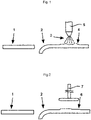
- thermoformed part 1 shows a schematic representation of the production of a thermoformed part.
- a semi-finished product 1 which is usually made of plastic and is in the form of a circuit board or a plate, the final thermoformed part 2 is obtained.
- the semi-finished product 1 is heated before a pressing process or during the pressing process, so that the semi-finished product 1 made of plastic can be plastically deformed.
- This can be achieved in various ways, for example by placing the semi-finished product 1 in an oven or exposing it to infrared radiation.
- the stamp used for forming or for carrying out the pressing process or the die used for this purpose itself brings about the increase in temperature of the semi-finished product 1 required for forming.
- the punch or the die is heated to such an extent that when it comes into contact with the semi-finished product 1, the semi-finished product 1 is brought to the required temperature, so that a subsequent application of pressure produces the desired deformation.
- the nozzle valve system 5 shown is designed to apply a fluid 3, for example water or the like, to the semi-finished product 1. If the reshaping is now carried out by placing the stamp and exerting the compressive force, the desired geometrically indeterminate shape 4 of the surface area can thereby be produced.
- a fluid for example water or the like
- the geometrically determined shape 6 can be achieved by a (tempered) stamp or die or with an additional tool 7 that is used only after the semi-finished product 1 has been first formed.
- a (tempered) stamp or die or with an additional tool 7 that is used only after the semi-finished product 1 has been first formed.
- additional tool 7 For example lets the geometrically defined form achieved in this way can be described by a honeycomb structure or other raised partial areas.
Landscapes
- Engineering & Computer Science (AREA)
- Mechanical Engineering (AREA)
- Blow-Moulding Or Thermoforming Of Plastics Or The Like (AREA)
Abstract
Description
- Die Erfindung betrifft ein Thermoformteil, insbesondere einen Innenbehälter für ein Kühl- und/oder Gefriergerät.
- Im Rahmen der Herstellung von Kühl- und/oder Gefriergeräten ist es bekannt, die Geräteinnenbehälter durch Thermoformen eines Halbzeugs, die aus einem thermoplastischen Kunststoff bestehen können, herzustellen. Dabei wird eine sogenannte Kunststoffplatine zunächst in einer Aufwärmstation auf eine Temperatur erwärmt, bei welcher sich der Kunststoff plastisch verformen lässt. Die so erwärmte Platine wird an eine Werkzeugstation weitergegeben und dort unter Anlegen einer Druckdifferenz mittels Einpressen eines Werkzeugs, beispielsweise eine Matrize oder eine Stempels, geformt.
- In der weiteren Verarbeitung ist es möglich, dass unterschiedliche Bauteile an das so erzeugte Thermoformteil angebracht werden und ein Kleber oder auch ein Schaum beim Verschäumen mit dem Thermoformteil in Kontakt kommt. Um beispielsweise das Ankleben von Bauteilen an dem Thermoformteil durchzuführen, ist auf einen auf die Zusammensetzung des Thermoformteils abgestimmten Kleber zu achten, der eine über die Produktlebensdauer stabile Verbindung gewährleistet.
- Darüber hinaus stellen Thermoformteile auch wesentliche strukturelle Elemente (bspw. bei einer Nutzung in Kühl- und/oder Gefriergeräten) dar, sodass diese eine möglichst hohe mechanische und/oder chemische Stabilität aufweisen sollen.
- Es ist jedoch auch das gleichzeitige Bestreben des Fachmanns, die Ressourcen beim Erstellen eines solchen Thermoformteils und auch bei den mit den Thermoformteil in Zusammenhang stehenden nachgelagerten Arbeitsschritten zu minimieren, um Kosten zu senken.
- Dies gelingt mit einem Thermoformteil, das sämtliche Merkmale eines der unabhängigen Ansprüche aufweist. Weitere vorteilhafte Ausgestaltungen des Thermoformteils finden sich dabei in den abhängigen Ansprüchen.
- Das erfindungsgemäße Thermoformteil, das insbesondere einen Innenbehälter für ein Kühl- und/oder Gefriergerät darstellen kann, umfasst dabei ein aus einem Halbzeug durch Thermoformen gebildetes Formteil, das dadurch gekennzeichnet, dass das Formteil in einem Oberflächenbereich eine geometrisch unbestimmte Form aufweist, wobei der Oberflächenbereich eine nicht-glatte, nichtrillige und ungerichtete Gestalt besitzt.
- Dabei kann auch vorgesehen sein, dass die Rauheit des Oberflächenbereichs sich von derjenigen unterscheidet, die in einem angrenzenden zu dem Oberflächenbereich vorgesehenen Bereich vorliegt.
- Durch die spezifische Ausgestaltung des Oberflächenbereichs des Thermoformteils vergrößert sich dessen Oberfläche, sodass eine bessere Haftung von Klebern oder einer Verschäumung erreichbar ist. Die dabei vergrößerte Oberfläche bietet mehr Platz zum Ansetzen einer Klebeverbindung, sodass zum Erreichen einer erforderlichen Klebekraft eine geringere Klebefläche oder ein nicht so stark haftendes Klebemittel Verwendung finden kann.
- Vorteilhaft an der vorliegenden Erfindung ist, dass keine weiteren Füllstoffe oder Füllmaterialien erforderlich sind und eine Oberflächenänderung bzw. eine Materialaufdickung durch denselben Werkstoff, aus dem auch das Thermoformteil ist, möglich ist.
- Nach einer vorteilhaften Modifikation der vorliegenden Erfindung kann vorgesehen sein, dass der Oberflächenbereich eine Ansammlung von unregelmäßig verteilten Erhebungen und Vertiefungen aufweist, vorzugsweise mit einer Oberflächenstruktur, die einer Raufasertapete oder einer Orangenhaut nachempfunden ist.
- Durch das Vorsehen von unregelmäßig verteilten Erhebungen und Vertiefungen wird der gewünschte Effekt erreicht, dass die dabei zur Verfügung stehende Oberfläche, die beispielsweise mit einem später aufgetragenen Klebstoff in Verbindung kommt, vergrößert wird. Die Struktur des Oberflächenbereichs und/oder dessen optische Erscheinung lässt sich am besten mit einer Raufasertapete bzw. der Haut eine Orange beschreiben, da hierbei ebenfalls unregelmäßig verteilte Erhebungen und/oder Vertiefungen vorgesehen sind, die diesen Oberflächen ihre charakteristische Prägung verleihen.
- Insbesondere bei nachfolgenden Arbeitsschritten, bspw. einem Einbringen von Schaum in einen Zwischenwandbereich eines Kühl- und/oder Gefriergeräts, bei dem der Innenbehälter durch das Thermoformteil gebildet ist, ist es von großem Vorteil, wenn der dabei eingebrachte Schaum die verschiedenen Bestandteile fest miteinander verklebt. So ist es dann möglich, auf andere Befestigungsmittel zu verzichten oder eine Stabilität des Kühl- und/oder Gefriergeräts zu erreichen, die vorher nicht erreichbar war.
- Dabei kann ferner vorgesehen sein, dass die Erhebungen unterschiedlich groß und/oder unterschiedlich hoch ausgeprägt sein können. Wie bei einem ungerichteten Erscheinungsbild üblich, ist die Struktur des Oberflächenbereichs in gewissem Maße zufällig oder besitzt zumindest die Erscheinung eines zufälligen, sich nicht wiederholenden Musters.
- Demnach kann es nach der Erfindung auch vorgesehen sein, dass die Vertiefungen unterschiedlich groß und/oder unterschiedlich tief ausgeprägt sein können. Es gilt also hier für die Vertiefungen des Oberflächenbereichs dasselbe wie für die Erhebungen des Oberflächenbereichs, sodass auch hier eine Regelmäßigkeit nicht vorhanden sein muss.
- Darüber hinaus betrifft die Erfindung ein Thermoformteil, insbesondere einen Innenbehälter für ein Kühl- und/oder Gefriergerät, welches ein aus einem Halbzeug durch Thermoformen gebildetes Formteil aufweist. Das Formteil weist in einem Oberflächenbereich eine geometrisch bestimmte Form auf, wobei der Oberflächenbereich gegenüber hierzu angrenzenden Bereichen des Formteils erhaben ist, sich aber in der Oberflächenstruktur und -beschaffenheit hiervon nicht unterscheidet.
- Durch die veränderte Geometrie, hervorgerufen durch die Erhebung in dem Oberflächenbereich ergibt sich eine verbesserte mechanische und/oder chemische Stabilität des Thermoformteils.
- Dabei kann auch vorgesehen sein, dass die Rauheit des Oberflächenbereichs sich von derjenigen unterscheidet, die in angrenzenden Bereichen zu dem Oberflächenbereich vorliegen.
- Nach einer optionalen Modifikation der vorliegenden Erfindung kann vorgesehen sein, dass die Dicke des Formteils in dem Oberflächenbereich gegenüber hierzu angrenzenden Bereichen größer ist.
- Weiter kann hierbei vorgesehen sein, dass der Oberflächenbereich die Ausgestaltung einer erhabenen Wabenstruktur besitzt.
- Die Erfindung betrifft ferner ein Verfahren zum Herstellen eines Thermoformteils nach einer der vorstehend diskutierten Varianten, wobei das Verfahren die nachfolgenden Schritte umfasst:
- Erwärmen eines Kunststoff-Halbzeugs auf eine Temperatur, die ein plastisches Umformen zulässt, und
- Pressen des Kunststoff-Halbzeugs durch Aufbringen einer Druckkraft, vorzugsweise durch Einpressen eines Stempels oder einer Matrize.
- Dabei wird das typischerweise aus Kunststoff bestehende Halbzeug erwärmt und, wenn es eine Temperatur erreicht hat, die ein plastisches Umformen erlaubt, durch einen Stempel oder eine Matrize geformt. Dabei wird der Stempel bzw. die Matrize mit hohem Druck auf das erwärmte Halbzeug aufgepresst, sodass das Halbzeug in die gewünschte Form gebracht wird. In der Regel ist dabei auch eine Stempel-Gegenfläche vorgesehen, in welche die andere, nicht mit dem Stempel bzw. der Matrize zusammenwirkende flächige Seite des Halbzeugs eingepresst wird, so dass das Halbzeug eine gewünschte vorgegebene Form erreicht.
- Um nun die spezifische Form eines Oberflächenbereichs des so gebildeten Formteils zu erreichen, gibt es verschiedene Ansätze.
- Zum einen kann nach der Erfindung vorgesehen sein, dass beim Herstellen des Thermoformteils ferner ein Temperaturgradient in dem Kunststoff-Halbzeug vor oder während einem Formen des Kunststoff-Halbzeugs erzeugt wird, wobei die räumliche Anordnung des Temperaturgradienten auf den Pressvorgang des Stempels abgestimmt und/oder durch den Pressvorgang eingebracht wird, vorzugsweise durch Einpressen eines Stempels der an seiner Pressfläche einen über seine flächige Seite verlaufenden Temperaturgradienten aufweist. Demnach kann also vorgesehen sein, dass unterschiedliche Bereiche des Stempels unterschiedliche Temperaturen aufweisen.
- Die Variation der Temperatur über die Fläche des zu formenden oder in der Formung befindlichen Halbzeugs ermöglicht, dass die unterschiedlich temperierten Bereiche des Halbzeugs auf identischen Druck unterschiedlich reagieren. Ist es beispielsweise gewünscht eine Verdickung im Durchmesser des Formteils hervorzurufen, kann eine entsprechende Fläche des Halbzeug stärker erwärmt werden, sodass beim Pressvorgang diese Teils des Halbzeug leichter in den dickeren Teil gedrängt werden können.
- Weiter kann nach der Erfindung vorgesehen sein, dass das Vorsehen des Temperaturgradienten durch Aufbringen eines Fluids, bspw. eines Kühlfluids auf das noch nicht verformte Kunststoff-Halbzeug, vorzugsweise durch Benetzen von dessen Oberfläche erfolgt, wobei das Kühlfluid auf einem Bereich des Kunststoff-Halbzeugs aufgebracht wird, der nach einem Formen dem Oberflächenbereich des Formteils entspricht, der die geometrisch unbestimmte Form besitzt.
- Dabei kann vorgesehen sein, dass das Fluid auf das bereits erwärmte Halbzeug aufgebracht wird, wohingegen es jedoch auch möglich ist, dass das Fluid auf das noch nicht erwärmte Halbzeug aufgebracht wird und die Erwärmung durch einen entsprechend heißen Stempel oder eine entsprechend heiße Matrize in das Halbzeug eingebracht wird. Vorteilhafterweise wird dabei auch das Fluid erwärmt, wobei dies dann, beispielsweise durch ein Verdampfen des Fluids oder dergleichen zu der gewünschten Gestaltung des Oberflächenbereichs mit seiner geometrisch unbestimmten Form beiträgt.
- Weiter kann vorgesehen sein, dass ein beim Pressvorgang genutzter Stempel oder eine Stempel-Gegenfläche eine nicht-glatte, nichtrillige und ungerichtete Gestalt aufweist. Diese Form des Stempels bzw. der Matrize und/oder der entsprechenden Gegenform kann ebenfalls dazu beitragen, dass die gewünschte geometrisch unbestimmte Form erreicht wird.
- Ferner kann bei dem Verfahren vorgesehen sein, dass die Temperatur in dem Bereich des Halbzeugs, das nach der Umformung dem Oberflächenbereich mit der geometrisch unbestimmten Oberfläche entspricht, oberhalb des Schmelzpunkts des Halbzeugs liegt und vor oder während den Pressvorgang erreicht wird, wobei vorzugsweise bei einem Abheben eines den Pressvorgang durchführenden Stempels die geometrisch unbestimmte Form des Oberflächenbereichs entsteht.
- Die Temperatur kann dabei in bestimmten Bereichen des Halbzeugs so hoch werden, dass sich das Halbzeug dort verflüssigt, wobei es dann vorzugsweise bei einem Abheben des Stempels oder der Matrize zu der unbestimmten Form in dem Oberflächenbereich kommt.
- Nach der Erfindung kann ferner vorgesehen sein, dass nach einem Pressvorgang ein weiterer Formungsschritt ausgeführt wird, um den Oberflächenbereich mit der geometrisch bestimmten Form zu bilden, vorzugsweise durch ein Werkzeug, das zusätzlich zu dem den Pressvorgang durchführenden Werkzeug vorgesehen ist.
- Demnach ist also auch nach einem Pressvorgang das weitere Bearbeiten des bereits verformten Thermoformteils durch ein weiteres Werkzeug möglich, um die geometrisch bestimmte Form zu erlangen.
- Die Erfindung betrifft ferner ein Kühl- und/oder Gefriergerät mit einem Thermoformteil als Innenbehälter nach einer der vorstehend diskutierten Varianten.
- Die Erfindung betrifft ferner Kühl- und/oder Gefriergerät mit einem Thermoformteil als Innenbehälter, dass nach einem der Verfahren einer der vorstehenden Varianten hergestellt worden ist.
- Weitere Vorteile, Merkmale und Einzelheiten der Erfindung werden anhand der Figurenbeschreibung ersichtlich. Dabei zeigen:
- Fig. 1:
- eine schematische Darstellung zur Herstellung eines erfindungsgemäßen Thermoformteils mit einem Oberflächenbereich, der eine geometrisch unbestimmte Form aufweist, und
- Fig. 2:
- eine schematische Darstellung zur Herstellung eines erfindungsgemäßen Thermoformteils mit einem Oberflächenbereich, der eine geometrisch bestimmte Form aufweist.
-
Fig. 1 zeigt eine schematische Darstellung zur Herstellung eines Thermoformteils. Ausgehend von einem Halbzeug 1, das in der Regel aus Kunststoff besteht und in der Form einer Platine oder einer Platte vorliegt, wird das finale Thermoformteil 2 gewonnen. - Hierzu ist es von Vorteil, dass das Halbzeug 1 vor einem Pressvorgang oder bei dem Pressvorgang erwärmt wird, sodass sich das aus Kunststoff bestehende Halbzeug 1 plastisch verformen lässt. Dies kann auf verschiedene Arten erreicht werden, beispielsweise durch Einbringen des Halbzeugs 1 in einen Ofen oder einem Aussetzen einer Infrarotstrahlung. Weiter ist es darüber hinaus möglich, dass der zum Umformen bzw. zum Ausführen des Pressvorgangs genutzte Stempel oder die hierfür herangezogene Matrize selbst die zur Umformung erforderliche Temperaturerhöhung des Halbzeug 1 bewirkt. Dabei wird der Stempel oder die Matrize so stark erhitzt, dass bei einem Kontaktieren mit dem Halbzeug 1 dieses vollständig auf die erforderliche Temperatur gebracht wird, sodass ein anschließendes Ausüben von Druck die gewünschte Umformung erzeugt.
- Das dargestellte Düsenventilsystem 5 ist dazu ausgelegt, ein Fluid 3, beispielsweise Wasser oder dergleichen, auf das Halbzeug 1 aufzubringen. Wird nun durch Aufsetzen des Stempels und Ausüben der Druckkraft die Umformung vorgenommen, kann dadurch die gewünschte geometrisch unbestimmte Form 4 des Oberflächenbereichs erzeugt werden.
-
Fig. 2 zeigt eine schematische Darstellung zur Herstellung eines Thermoformteils, bei der ein Oberflächenbereich eine geometrisch bestimmte Form 6 aufweist. Dabei kann die geometrisch bestimmte Form 6 durch einen (temperierten) Stempel bzw. Matrize oder aber mit einem Zusatzwerkzeug 7 erreicht werden, das erst nach einem ersten Umformen des Halbzeug 1 zum Einsatz kommt. Beispielsweise lässt sich die dadurch erreichte geometrisch bestimmte Form durch eine Wabenstruktur oder andere erhabene partielle Bereiche beschreiben.
Claims (15)
- Thermoformteil (2), insbesondere Innenbehälter für ein Kühl- und/oder Gefriergerät, umfassend:ein aus einem Halbzeug (1) durch Thermoformen gebildetes Formteil (2),dadurch gekennzeichnet, dassdas Formteil (2) in einem Oberflächenbereich (4) eine geometrisch unbestimmte Form aufweist, wobeider Oberflächenbereich (4) eine nicht-glatte, nichtrillige und ungerichtete Gestalt besitzt.
- Thermoformteil (2) nach dem vorhergehenden Anspruch 1, wobei der Oberflächenbereich (4) eine Ansammlung von unregelmäßig verteilten Erhebungen und Vertiefungen aufweist, vorzugsweise mit einer Oberflächenstruktur, die einer Raufasertapete oder einer Orangenhaut nachempfunden ist.
- Thermoformteil (2) nach dem vorhergehenden Anspruch 2, wobei die Erhebungen unterschiedlich groß ausgeprägt sein können und/oder unterschiedlich hoch ausgeprägt sein können.
- Thermoformteil (2) nach einem der vorhergehenden Ansprüche 2 oder 3, wobei die Vertiefungen unterschiedlich groß ausgeprägt sein können und/oder unterschiedlich tief ausgeprägt sein können.
- Thermoformteil (2), insbesondere Innenbehälter für ein Kühl- und/oder Gefriergerät, umfassend:ein aus einem Halbzeug (1) durch Thermoformen gebildetes Formteil (2),dadurch gekennzeichnet, dassdas Formteil (2) in einem Oberflächenbereich eine geometrisch bestimmte Form aufweist, wobeider Oberflächenbereich (6) gegenüber hierzu angrenzenden Bereichen des Formteils (2) erhaben ist, sich aber in der Oberflächenstruktur und -beschaffenheit hiervon nicht unterscheidet.
- Thermoformteil (2) nach dem vorhergehenden Anspruch, wobei die Dicke des Formteils (2) in dem Oberflächenbereich (6) gegenüber hierzu angrenzenden Bereichen größer ist.
- Thermoformteil (2) nach einem der vorhergehenden Ansprüche 5 oder 6, wobei der Oberflächenbereich (6) die Ausgestaltung einer erhabenen Wabenstruktur besitzt.
- Verfahren zum Herstellen eines Thermoformteils (2) nach einem der vorhergehenden Ansprüche, wobei das Verfahren die nachfolgenden Schritte umfasst:Erwärmen eines Kunststoff-Halbzeugs (1) auf eine Temperatur, die ein plastisches Umformen zulässt, undPressen des Kunststoff-Halbzeugs (1) durch Aufbringen einer Druckkraft, vorzugsweise durch Einpressen eines Stempels.
- Verfahren nach dem vorhergehenden Anspruch 8, ferner umfassen die Schritte:Erzeugen eines Temperaturgradienten in dem Kunststoff-Halbzeug (1) vor oder während einem Formen des Kunststoff-Halbzeugs (1),wobei die räumliche Anordnung des Temperaturgradienten auf den Pressvorgang abgestimmt und/oder durch den Pressvorgang eingebracht wird, vorzugsweise durch Einpressen eines Stempels der an seiner Pressfläche einen Temperaturgradienten aufweist.
- Verfahren nach einem der vorhergehenden Ansprüche 8 oder 9, ferner umfassend die Schritte:Aufbringen eines Fluids (3), bspw. Kühlfluids, auf das noch nicht verformte Kunststoff-Halbzeug (1), vorzugsweise durch Benetzen von dessen Oberfläche, wobeidas Kühlfluid (3) auf einem Bereich des Kunststoff-Halbzeugs (1) aufgebracht wird, der nach einem Formen dem Oberflächenbereich des Formteils (2) entspricht, der die geometrisch unbestimmte Form besitzt.
- Verfahren nach einem der vorhergehenden Ansprüche 8 bis 10 zum Herstellen eines Thermoformteils (2) nach den Ansprüchen 1 bis 4, wobei
ein beim Pressvorgang genutzter Stempel oder eine Stempel-Gegenfläche eine nicht-glatte, nichtrillige und ungerichtete Gestalt aufweist. - Verfahren nach einem der vorhergehenden Ansprüche 8 bis 11 zum Herstellen eines Thermoformteils (2) nach den Ansprüchen 1 bis 4, wobei die Temperatur in dem Bereich des Halbzeug, das nach der Umformung dem Oberflächenbereichs mit der geometrisch unbestimmten Fläche entspricht, oberhalb des Schmelzpunkts des Halbzeugs liegt und vor oder während den Pressvorgang erreicht wird, wobei vorzugsweise bei einem Abheben eines den Pressvorgang durchführenden Stempels die geometrisch unbestimmte Form des Oberflächenbereichs entsteht.
- Verfahren nach einem der vorhergehenden Ansprüche 8 bis 11 zum Herstellen eines Thermoformteils (2) nach den Ansprüchen 5 bis 7, wobei
nach einem Pressvorgang ein weiterer Formungsschritt ausgeführt wird, um den Oberflächenbereich mit der geometrisch bestimmten Form zu bilden, vorzugsweise durch ein Werkzeug (7), das zusätzlich zu dem den Pressvorgang durchführenden Werkzeug vorgesehen ist. - Kühl- und/oder Gefriergerät mit einem Thermoformteil als Innenbehälter nach einem der vorhergehenden Ansprüche 1-7.
- Kühl- und/oder Gefriergerät mit einem Thermoformteil als Innenbehälter, dass nach einem der Verfahren nach den Ansprüchen 8-13 hergestellt worden ist.
Applications Claiming Priority (1)
| Application Number | Priority Date | Filing Date | Title |
|---|---|---|---|
| DE102020134732.4A DE102020134732A1 (de) | 2020-12-22 | 2020-12-22 | Thermoformteil |
Publications (2)
| Publication Number | Publication Date |
|---|---|
| EP4019226A1 true EP4019226A1 (de) | 2022-06-29 |
| EP4019226B1 EP4019226B1 (de) | 2025-07-30 |
Family
ID=79024539
Family Applications (1)
| Application Number | Title | Priority Date | Filing Date |
|---|---|---|---|
| EP21214633.6A Active EP4019226B1 (de) | 2020-12-22 | 2021-12-15 | Thermoformteil |
Country Status (2)
| Country | Link |
|---|---|
| EP (1) | EP4019226B1 (de) |
| DE (1) | DE102020134732A1 (de) |
Citations (3)
| Publication number | Priority date | Publication date | Assignee | Title |
|---|---|---|---|---|
| EP0937180A1 (de) * | 1996-11-08 | 1999-08-25 | The Procter & Gamble Company | Dreidimensionale bahnförmige materialen und verfahren und vorrichtung zu ihrer herstellung |
| EP2345860A2 (de) * | 2009-12-04 | 2011-07-20 | BSH Bosch und Siemens Hausgeräte GmbH | Kältegerät, insbesondere Haushaltskältegerät, sowie Verfahren zur Herstellung eines solchen Kältegerätes |
| WO2013174741A1 (de) * | 2012-05-23 | 2013-11-28 | BSH Bosch und Siemens Hausgeräte GmbH | Kältegerät mit türinnenplatte |
Family Cites Families (7)
| Publication number | Priority date | Publication date | Assignee | Title |
|---|---|---|---|---|
| US6749794B2 (en) | 2001-08-13 | 2004-06-15 | R + S Technik Gmbh | Method and apparatus for molding components with molded-in surface texture |
| DE10313495A1 (de) | 2003-03-25 | 2004-10-14 | Fagerdala Deutschland Gmbh | Kunststoff-Hohlkörper und Verfahren zu dessen Herstellung |
| DE102005001099B4 (de) | 2005-01-08 | 2009-02-19 | Frimo Group Gmbh | Verfahren und Vorrichtung zur Herstellung einer thermogeformten und mit einer Oberflächennarbung versehenen Kunststofffolie |
| EP1704978A1 (de) | 2005-03-22 | 2006-09-27 | ArvinMeritor GmbH | Folien-Tiefzieh- oder Folien-Schäumform und deren Herstellungsverfahren sowie Verfahren zum Herstellen eines Verbundbauteils |
| DE102005062078B4 (de) | 2005-12-22 | 2009-10-22 | Peguform Gmbh | Verfahren zur Herstellung von Kunststoffteilen mit einer Oberflächenstruktur, verfahrensgemäß hergestellte Kunststoffteile sowie Formwerkzeuge zu ihrer Herstellung |
| DE102011008722A1 (de) | 2011-01-17 | 2012-07-19 | Liebherr-Hausgeräte Ochsenhausen GmbH | Haushaltsgerät |
| EP2829828B1 (de) * | 2013-07-25 | 2016-06-29 | Electrolux Appliances Aktiebolag | Verfahren zum Herstellen einer Kühlvorrichtung |
-
2020
- 2020-12-22 DE DE102020134732.4A patent/DE102020134732A1/de active Pending
-
2021
- 2021-12-15 EP EP21214633.6A patent/EP4019226B1/de active Active
Patent Citations (3)
| Publication number | Priority date | Publication date | Assignee | Title |
|---|---|---|---|---|
| EP0937180A1 (de) * | 1996-11-08 | 1999-08-25 | The Procter & Gamble Company | Dreidimensionale bahnförmige materialen und verfahren und vorrichtung zu ihrer herstellung |
| EP2345860A2 (de) * | 2009-12-04 | 2011-07-20 | BSH Bosch und Siemens Hausgeräte GmbH | Kältegerät, insbesondere Haushaltskältegerät, sowie Verfahren zur Herstellung eines solchen Kältegerätes |
| WO2013174741A1 (de) * | 2012-05-23 | 2013-11-28 | BSH Bosch und Siemens Hausgeräte GmbH | Kältegerät mit türinnenplatte |
Also Published As
| Publication number | Publication date |
|---|---|
| EP4019226B1 (de) | 2025-07-30 |
| DE102020134732A1 (de) | 2022-06-23 |
Similar Documents
| Publication | Publication Date | Title |
|---|---|---|
| EP3105038B1 (de) | Verfahren zur herstellung eines verbundbauteils | |
| EP1646492B1 (de) | Innenausstattungskomponenten von kraftfahrzeugen mit einem definierten oberflächenprofil | |
| DE102013114245B3 (de) | Verfahren und Vorrichtung zur Herstellung warmumgeformter Radschüsseln | |
| WO2012085070A1 (de) | Verfahren zur herstellung von oberflächenendbearbeiteten leichtbauteilen mit hohem naturfaseranteil und integrierten befestigungselementen | |
| DE102004054228A1 (de) | Verfahren und Vorrichtung zur Herstellung eines Verbundteils | |
| DE102011055654A1 (de) | Herstellverfahren für ein Verbundblechteil mit metallischem Bereich | |
| DE102009038896B4 (de) | Verfahren zur Herstellung eines aus einem ersten und zweiten Bauteil gefügten Strukturbauteils sowie Vorrichtung zur Durchführung des Verfahrens | |
| DE19959654A1 (de) | Verfahren zur Herstellung von Innenausstattungskomponenten von Kraftfahrzeugen | |
| EP0657265A1 (de) | Verfahren zur Herstellung flächiger kaschierter Teile unter Verwendung von Gitterförmigen Vorformlingen | |
| EP4019226B1 (de) | Thermoformteil | |
| DE102015203642A1 (de) | Verfahren zur Herstellung eines Bauteils durch Umformen eines mehrlagigen flächigen Halbzeugs mit weicher Kernlage und hiermit hergestelltes Bauteil | |
| DE19505523A1 (de) | Verfahren und Vorrichtung zur Herstellung eines flächigen Verkleidungselementes | |
| EP1268099B1 (de) | Verfahren zum herstellen von bauteilen mittels eines fliessfähigen wirkmediums sowie eines formwerkzeugs | |
| DE102012104316A1 (de) | Verfahren zur Fertigung eines Bauteils | |
| DE102013110761B4 (de) | Verfahren zum Herstellen eines metallischen Verbundbauteils und metallisches Verbundbauteil | |
| AT512204B1 (de) | Formteil und thermoformverfahren zur herstellung eines mehrere schichten aufweisenden formteils | |
| EP0011132A1 (de) | Verfahren zur Herstellung von Formkörpern aus kaschierten Polyurethan-Hartschaumstoffplatten | |
| DE4423551A1 (de) | Preß-Formgebungsverfahren sowie Vorrichtung zur Durchführung des Verfahrens | |
| DE2929992C2 (de) | ||
| DE102015225363A1 (de) | Verfahren zur Herstellung eines Zierelements für ein Fahrzeug | |
| DE102016108290B3 (de) | Schweisswerkzeug und verfahren zum verschweissen von kunststoffteilen | |
| DE102013214536A1 (de) | Verfahren zur Bearbeitung eines aus einem Faser-Kunststoff-Verbund gebildeten Bauteils | |
| DE4040925A1 (de) | Verfahren und vorrichtung zum herstellen von formteilen aus ebenen zuschnitten oder vorformteilen aus mit bindemitteln versehenen zellulose- oder lignozellulose-wirrfaservliesen | |
| DE102008056307A1 (de) | Vorrichtung und Verfahren zur Herstellung von Formbauteilen durch Formgebung von Prepregs | |
| DE102021104122A1 (de) | Verfahren zur Herstellung eines Dekorformteils |
Legal Events
| Date | Code | Title | Description |
|---|---|---|---|
| PUAI | Public reference made under article 153(3) epc to a published international application that has entered the european phase |
Free format text: ORIGINAL CODE: 0009012 |
|
| STAA | Information on the status of an ep patent application or granted ep patent |
Free format text: STATUS: THE APPLICATION HAS BEEN PUBLISHED |
|
| AK | Designated contracting states |
Kind code of ref document: A1 Designated state(s): AL AT BE BG CH CY CZ DE DK EE ES FI FR GB GR HR HU IE IS IT LI LT LU LV MC MK MT NL NO PL PT RO RS SE SI SK SM TR |
|
| STAA | Information on the status of an ep patent application or granted ep patent |
Free format text: STATUS: REQUEST FOR EXAMINATION WAS MADE |
|
| 17P | Request for examination filed |
Effective date: 20221229 |
|
| GRAP | Despatch of communication of intention to grant a patent |
Free format text: ORIGINAL CODE: EPIDOSNIGR1 |
|
| STAA | Information on the status of an ep patent application or granted ep patent |
Free format text: STATUS: GRANT OF PATENT IS INTENDED |
|
| RIC1 | Information provided on ipc code assigned before grant |
Ipc: F25D 23/06 20060101ALN20250226BHEP Ipc: B29L 31/00 20060101ALN20250226BHEP Ipc: B29C 65/48 20060101ALI20250226BHEP Ipc: B29C 65/00 20060101ALI20250226BHEP Ipc: B29C 51/00 20060101ALI20250226BHEP Ipc: B29C 35/16 20060101ALI20250226BHEP Ipc: B29C 43/52 20060101ALI20250226BHEP Ipc: B29C 43/02 20060101ALI20250226BHEP Ipc: B29C 59/02 20060101ALI20250226BHEP Ipc: B29C 51/42 20060101ALI20250226BHEP Ipc: B29C 51/26 20060101AFI20250226BHEP |
|
| RIC1 | Information provided on ipc code assigned before grant |
Ipc: F25D 23/06 20060101ALN20250311BHEP Ipc: B29L 31/00 20060101ALN20250311BHEP Ipc: B29C 65/48 20060101ALI20250311BHEP Ipc: B29C 65/00 20060101ALI20250311BHEP Ipc: B29C 51/00 20060101ALI20250311BHEP Ipc: B29C 35/16 20060101ALI20250311BHEP Ipc: B29C 43/52 20060101ALI20250311BHEP Ipc: B29C 43/02 20060101ALI20250311BHEP Ipc: B29C 59/02 20060101ALI20250311BHEP Ipc: B29C 51/42 20060101ALI20250311BHEP Ipc: B29C 51/26 20060101AFI20250311BHEP |
|
| INTG | Intention to grant announced |
Effective date: 20250321 |
|
| GRAS | Grant fee paid |
Free format text: ORIGINAL CODE: EPIDOSNIGR3 |
|
| GRAA | (expected) grant |
Free format text: ORIGINAL CODE: 0009210 |
|
| STAA | Information on the status of an ep patent application or granted ep patent |
Free format text: STATUS: THE PATENT HAS BEEN GRANTED |
|
| AK | Designated contracting states |
Kind code of ref document: B1 Designated state(s): AL AT BE BG CH CY CZ DE DK EE ES FI FR GB GR HR HU IE IS IT LI LT LU LV MC MK MT NL NO PL PT RO RS SE SI SK SM TR |
|
| REG | Reference to a national code |
Ref country code: GB Ref legal event code: FG4D Free format text: NOT ENGLISH |
|
| REG | Reference to a national code |
Ref country code: CH Ref legal event code: EP |
|
| REG | Reference to a national code |
Ref country code: DE Ref legal event code: R096 Ref document number: 502021008139 Country of ref document: DE |
|
| REG | Reference to a national code |
Ref country code: IE Ref legal event code: FG4D Free format text: LANGUAGE OF EP DOCUMENT: GERMAN |
|
| REG | Reference to a national code |
Ref country code: NL Ref legal event code: MP Effective date: 20250730 |
|
| PG25 | Lapsed in a contracting state [announced via postgrant information from national office to epo] |
Ref country code: PT Free format text: LAPSE BECAUSE OF FAILURE TO SUBMIT A TRANSLATION OF THE DESCRIPTION OR TO PAY THE FEE WITHIN THE PRESCRIBED TIME-LIMIT Effective date: 20251202 |
|
| PG25 | Lapsed in a contracting state [announced via postgrant information from national office to epo] |
Ref country code: IS Free format text: LAPSE BECAUSE OF FAILURE TO SUBMIT A TRANSLATION OF THE DESCRIPTION OR TO PAY THE FEE WITHIN THE PRESCRIBED TIME-LIMIT Effective date: 20251130 |
|
| PG25 | Lapsed in a contracting state [announced via postgrant information from national office to epo] |
Ref country code: NO Free format text: LAPSE BECAUSE OF FAILURE TO SUBMIT A TRANSLATION OF THE DESCRIPTION OR TO PAY THE FEE WITHIN THE PRESCRIBED TIME-LIMIT Effective date: 20251030 |
|
| REG | Reference to a national code |
Ref country code: LT Ref legal event code: MG9D |
|
| PGFP | Annual fee paid to national office [announced via postgrant information from national office to epo] |
Ref country code: AT Payment date: 20260113 Year of fee payment: 5 |
|
| PG25 | Lapsed in a contracting state [announced via postgrant information from national office to epo] |
Ref country code: FI Free format text: LAPSE BECAUSE OF FAILURE TO SUBMIT A TRANSLATION OF THE DESCRIPTION OR TO PAY THE FEE WITHIN THE PRESCRIBED TIME-LIMIT Effective date: 20250730 |
|
| PG25 | Lapsed in a contracting state [announced via postgrant information from national office to epo] |
Ref country code: NL Free format text: LAPSE BECAUSE OF FAILURE TO SUBMIT A TRANSLATION OF THE DESCRIPTION OR TO PAY THE FEE WITHIN THE PRESCRIBED TIME-LIMIT Effective date: 20250730 Ref country code: HR Free format text: LAPSE BECAUSE OF FAILURE TO SUBMIT A TRANSLATION OF THE DESCRIPTION OR TO PAY THE FEE WITHIN THE PRESCRIBED TIME-LIMIT Effective date: 20250730 |
|
| PG25 | Lapsed in a contracting state [announced via postgrant information from national office to epo] |
Ref country code: GR Free format text: LAPSE BECAUSE OF FAILURE TO SUBMIT A TRANSLATION OF THE DESCRIPTION OR TO PAY THE FEE WITHIN THE PRESCRIBED TIME-LIMIT Effective date: 20251031 |
|
| PG25 | Lapsed in a contracting state [announced via postgrant information from national office to epo] |
Ref country code: SE Free format text: LAPSE BECAUSE OF FAILURE TO SUBMIT A TRANSLATION OF THE DESCRIPTION OR TO PAY THE FEE WITHIN THE PRESCRIBED TIME-LIMIT Effective date: 20250730 |
|
| PG25 | Lapsed in a contracting state [announced via postgrant information from national office to epo] |
Ref country code: LV Free format text: LAPSE BECAUSE OF FAILURE TO SUBMIT A TRANSLATION OF THE DESCRIPTION OR TO PAY THE FEE WITHIN THE PRESCRIBED TIME-LIMIT Effective date: 20250730 |
|
| PG25 | Lapsed in a contracting state [announced via postgrant information from national office to epo] |
Ref country code: PL Free format text: LAPSE BECAUSE OF FAILURE TO SUBMIT A TRANSLATION OF THE DESCRIPTION OR TO PAY THE FEE WITHIN THE PRESCRIBED TIME-LIMIT Effective date: 20250730 Ref country code: BG Free format text: LAPSE BECAUSE OF FAILURE TO SUBMIT A TRANSLATION OF THE DESCRIPTION OR TO PAY THE FEE WITHIN THE PRESCRIBED TIME-LIMIT Effective date: 20250730 |
|
| PG25 | Lapsed in a contracting state [announced via postgrant information from national office to epo] |
Ref country code: RS Free format text: LAPSE BECAUSE OF FAILURE TO SUBMIT A TRANSLATION OF THE DESCRIPTION OR TO PAY THE FEE WITHIN THE PRESCRIBED TIME-LIMIT Effective date: 20251030 |
|
| PG25 | Lapsed in a contracting state [announced via postgrant information from national office to epo] |
Ref country code: ES Free format text: LAPSE BECAUSE OF FAILURE TO SUBMIT A TRANSLATION OF THE DESCRIPTION OR TO PAY THE FEE WITHIN THE PRESCRIBED TIME-LIMIT Effective date: 20250730 |
|
| PG25 | Lapsed in a contracting state [announced via postgrant information from national office to epo] |
Ref country code: RO Free format text: LAPSE BECAUSE OF FAILURE TO SUBMIT A TRANSLATION OF THE DESCRIPTION OR TO PAY THE FEE WITHIN THE PRESCRIBED TIME-LIMIT Effective date: 20250730 |
|
| PG25 | Lapsed in a contracting state [announced via postgrant information from national office to epo] |
Ref country code: SM Free format text: LAPSE BECAUSE OF FAILURE TO SUBMIT A TRANSLATION OF THE DESCRIPTION OR TO PAY THE FEE WITHIN THE PRESCRIBED TIME-LIMIT Effective date: 20250730 |
|
| PG25 | Lapsed in a contracting state [announced via postgrant information from national office to epo] |
Ref country code: DK Free format text: LAPSE BECAUSE OF FAILURE TO SUBMIT A TRANSLATION OF THE DESCRIPTION OR TO PAY THE FEE WITHIN THE PRESCRIBED TIME-LIMIT Effective date: 20250730 |
|
| PGFP | Annual fee paid to national office [announced via postgrant information from national office to epo] |
Ref country code: DE Payment date: 20251230 Year of fee payment: 5 |
|
| PG25 | Lapsed in a contracting state [announced via postgrant information from national office to epo] |
Ref country code: IT Free format text: LAPSE BECAUSE OF FAILURE TO SUBMIT A TRANSLATION OF THE DESCRIPTION OR TO PAY THE FEE WITHIN THE PRESCRIBED TIME-LIMIT Effective date: 20250730 |
|
| PG25 | Lapsed in a contracting state [announced via postgrant information from national office to epo] |
Ref country code: CZ Free format text: LAPSE BECAUSE OF FAILURE TO SUBMIT A TRANSLATION OF THE DESCRIPTION OR TO PAY THE FEE WITHIN THE PRESCRIBED TIME-LIMIT Effective date: 20250730 |
|
| PG25 | Lapsed in a contracting state [announced via postgrant information from national office to epo] |
Ref country code: SK Free format text: LAPSE BECAUSE OF FAILURE TO SUBMIT A TRANSLATION OF THE DESCRIPTION OR TO PAY THE FEE WITHIN THE PRESCRIBED TIME-LIMIT Effective date: 20250730 Ref country code: EE Free format text: LAPSE BECAUSE OF FAILURE TO SUBMIT A TRANSLATION OF THE DESCRIPTION OR TO PAY THE FEE WITHIN THE PRESCRIBED TIME-LIMIT Effective date: 20250730 |