EP4018920A1 - Pump system, fluid supply device and pressure detection method - Google Patents
Pump system, fluid supply device and pressure detection method Download PDFInfo
- Publication number
- EP4018920A1 EP4018920A1 EP21216139.2A EP21216139A EP4018920A1 EP 4018920 A1 EP4018920 A1 EP 4018920A1 EP 21216139 A EP21216139 A EP 21216139A EP 4018920 A1 EP4018920 A1 EP 4018920A1
- Authority
- EP
- European Patent Office
- Prior art keywords
- pressure
- vibration actuator
- pump system
- cuff
- sealed chamber
- Prior art date
- Legal status (The legal status is an assumption and is not a legal conclusion. Google has not performed a legal analysis and makes no representation as to the accuracy of the status listed.)
- Granted
Links
Images




Classifications
-
- F—MECHANICAL ENGINEERING; LIGHTING; HEATING; WEAPONS; BLASTING
- F04—POSITIVE - DISPLACEMENT MACHINES FOR LIQUIDS; PUMPS FOR LIQUIDS OR ELASTIC FLUIDS
- F04B—POSITIVE-DISPLACEMENT MACHINES FOR LIQUIDS; PUMPS
- F04B49/00—Control, e.g. of pump delivery, or pump pressure of, or safety measures for, machines, pumps, or pumping installations, not otherwise provided for, or of interest apart from, groups F04B1/00 - F04B47/00
- F04B49/08—Regulating by delivery pressure
-
- A—HUMAN NECESSITIES
- A61—MEDICAL OR VETERINARY SCIENCE; HYGIENE
- A61B—DIAGNOSIS; SURGERY; IDENTIFICATION
- A61B5/00—Measuring for diagnostic purposes; Identification of persons
- A61B5/02—Detecting, measuring or recording for evaluating the cardiovascular system, e.g. pulse, heart rate, blood pressure or blood flow
- A61B5/021—Measuring pressure in heart or blood vessels
- A61B5/02141—Details of apparatus construction, e.g. pump units or housings therefor, cuff pressurising systems, arrangements of fluid conduits or circuits
-
- F—MECHANICAL ENGINEERING; LIGHTING; HEATING; WEAPONS; BLASTING
- F04—POSITIVE - DISPLACEMENT MACHINES FOR LIQUIDS; PUMPS FOR LIQUIDS OR ELASTIC FLUIDS
- F04B—POSITIVE-DISPLACEMENT MACHINES FOR LIQUIDS; PUMPS
- F04B35/00—Piston pumps specially adapted for elastic fluids and characterised by the driving means to their working members, or by combination with, or adaptation to, specific driving engines or motors, not otherwise provided for
- F04B35/04—Piston pumps specially adapted for elastic fluids and characterised by the driving means to their working members, or by combination with, or adaptation to, specific driving engines or motors, not otherwise provided for the means being electric
-
- F—MECHANICAL ENGINEERING; LIGHTING; HEATING; WEAPONS; BLASTING
- F04—POSITIVE - DISPLACEMENT MACHINES FOR LIQUIDS; PUMPS FOR LIQUIDS OR ELASTIC FLUIDS
- F04B—POSITIVE-DISPLACEMENT MACHINES FOR LIQUIDS; PUMPS
- F04B39/00—Component parts, details, or accessories, of pumps or pumping systems specially adapted for elastic fluids, not otherwise provided for in, or of interest apart from, groups F04B25/00 - F04B37/00
-
- F—MECHANICAL ENGINEERING; LIGHTING; HEATING; WEAPONS; BLASTING
- F04—POSITIVE - DISPLACEMENT MACHINES FOR LIQUIDS; PUMPS FOR LIQUIDS OR ELASTIC FLUIDS
- F04B—POSITIVE-DISPLACEMENT MACHINES FOR LIQUIDS; PUMPS
- F04B39/00—Component parts, details, or accessories, of pumps or pumping systems specially adapted for elastic fluids, not otherwise provided for in, or of interest apart from, groups F04B25/00 - F04B37/00
- F04B39/12—Casings; Cylinders; Cylinder heads; Fluid connections
- F04B39/121—Casings
-
- F—MECHANICAL ENGINEERING; LIGHTING; HEATING; WEAPONS; BLASTING
- F04—POSITIVE - DISPLACEMENT MACHINES FOR LIQUIDS; PUMPS FOR LIQUIDS OR ELASTIC FLUIDS
- F04B—POSITIVE-DISPLACEMENT MACHINES FOR LIQUIDS; PUMPS
- F04B43/00—Machines, pumps, or pumping installations having flexible working members
- F04B43/02—Machines, pumps, or pumping installations having flexible working members having plate-like flexible members, e.g. diaphragms
-
- F—MECHANICAL ENGINEERING; LIGHTING; HEATING; WEAPONS; BLASTING
- F04—POSITIVE - DISPLACEMENT MACHINES FOR LIQUIDS; PUMPS FOR LIQUIDS OR ELASTIC FLUIDS
- F04B—POSITIVE-DISPLACEMENT MACHINES FOR LIQUIDS; PUMPS
- F04B43/00—Machines, pumps, or pumping installations having flexible working members
- F04B43/02—Machines, pumps, or pumping installations having flexible working members having plate-like flexible members, e.g. diaphragms
- F04B43/04—Pumps having electric drive
-
- F—MECHANICAL ENGINEERING; LIGHTING; HEATING; WEAPONS; BLASTING
- F04—POSITIVE - DISPLACEMENT MACHINES FOR LIQUIDS; PUMPS FOR LIQUIDS OR ELASTIC FLUIDS
- F04B—POSITIVE-DISPLACEMENT MACHINES FOR LIQUIDS; PUMPS
- F04B45/00—Pumps or pumping installations having flexible working members and specially adapted for elastic fluids
- F04B45/04—Pumps or pumping installations having flexible working members and specially adapted for elastic fluids having plate-like flexible members, e.g. diaphragms
-
- F—MECHANICAL ENGINEERING; LIGHTING; HEATING; WEAPONS; BLASTING
- F04—POSITIVE - DISPLACEMENT MACHINES FOR LIQUIDS; PUMPS FOR LIQUIDS OR ELASTIC FLUIDS
- F04B—POSITIVE-DISPLACEMENT MACHINES FOR LIQUIDS; PUMPS
- F04B45/00—Pumps or pumping installations having flexible working members and specially adapted for elastic fluids
- F04B45/04—Pumps or pumping installations having flexible working members and specially adapted for elastic fluids having plate-like flexible members, e.g. diaphragms
- F04B45/047—Pumps having electric drive
-
- F—MECHANICAL ENGINEERING; LIGHTING; HEATING; WEAPONS; BLASTING
- F04—POSITIVE - DISPLACEMENT MACHINES FOR LIQUIDS; PUMPS FOR LIQUIDS OR ELASTIC FLUIDS
- F04B—POSITIVE-DISPLACEMENT MACHINES FOR LIQUIDS; PUMPS
- F04B49/00—Control, e.g. of pump delivery, or pump pressure of, or safety measures for, machines, pumps, or pumping installations, not otherwise provided for, or of interest apart from, groups F04B1/00 - F04B47/00
- F04B49/06—Control using electricity
Definitions
- the present invention relates to a pump system, a fluid supply device and a pressure detection method.
- Each of patent document 1, patent document 2 and patent document 3 describes an electronic sphygmomanometer for measuring a blood pressure value of a user.
- the electronic sphygmomanometer has a configuration including a cuff attached to an arm of the user, a pump for supplying air into the cuff to increase pressure in the cuff and a pressure sensor for detecting the pressure in the cuff.
- the electronic sphygmomanometer disclosed in each of the patent documents 1, 2 and 3 has the configuration in which the pressure sensor is provided as a different component separated from the pump.
- the number of components of the electronic sphygmomanometer becomes large and the size of the electronic sphygmomanometer also becomes large.
- the present invention has been made in view of the above-described problem of the conventional art. Accordingly, it is an object of the present invention to provide a pump system which can be miniaturized by employing a configuration in which the pressure sensor is omitted and the pressure in the cuff can be detected by using the pump, a fluid supply device containing the pump system and a pressure detection method performed by the pump system.
- the pump system of the present invention can detect the pressure in the target object based on the consumption current of the vibration actuator which can be electromagnetically driven. Thus, it is possible to detect the pressure in the target object without using any pressure sensor. Therefore, it is possible to reduce the number of components of the pump system and reduce the size of the pump system.
- the fluid supply device of the present invention contains the above-described pump system. Therefore, the fluid supply device can receive the effect of the pump system and thus it is possible to reduce the size of the fluid supply device.
- the pressure detection method of the present invention can detect the pressure in the target object based on the consumption current of the vibration actuator which can be electromagnetically driven. Thus, it is possible to detect the pressure in the target object without using any pressure sensor. Therefore, it is possible to reduce the number of components of the pump system and reduce the size of the pump system.
- Fig. 1 is a perspective view showing an overall configuration of an electronic sphygmomanometer according to the preferred embodiment.
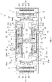
- Fig. 2 is a cross-sectional view of a pump.
- Fig. 3 is a cross-sectional view showing a driving principle of the pump shown in Fig. 2 .
- Fig. 4 is another cross-sectional view showing the driving principle of the pump shown in Fig. 2 .
- Fig. 5 is a schematic diagram showing a spring system of a vibration actuator.
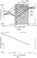
- Fig. 6 is a graph showing a relationship between a drive frequency and a consumption current of the vibration actuator.
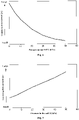
- Figs. 7 to 11 are graphs respectively showing different relationships between pressure in a sealed chamber and the consumption current.
- an upper side of the paper on which each of Figs. 2 to 4 is illustrated is sometimes referred to as "an upper side” and a lower side of the paper on which each of Figs. 2 to 4 is illustrated is sometimes referred to as "a lower side” for convenience of explanation.
- Fig. 1 shows an electronic sphygmomanometer 1 serving as a fluid supply device.
- the electronic sphygmomanometer 1 includes a cuff 2, a main body 3 and a tube 4 for connecting between the cuff 2 and the main body 3 to supply and discharge fluid.
- the cuff 2 is attached to a measurement target part such as an arm of a user.
- the cuff 2 has a bladder provided therein.
- the bladder is inflated when the fluid is supplied from the main body 3 into the bladder to compress the measurement target part.
- the main body 3 measures pressure in the cuff (target object) 2 to calculate a blood pressure value of the user based on a measurement result.
- the fluid to be supplied from the main body 3 into the bladder is not particularly limited. Although the fluid may be liquid or gas, it is preferable that the fluid is the gas. For convenience of explanation, the following description will be given with assuming that the fluid is air.
- the cuff 2 is wound onto the measurement target part of the user.
- the air is supplied from the main body 3 into the cuff 2 to make the pressure in the cuff 2 (referred to as "cuff pressure") higher than a maximum blood pressure of the user.
- the pressure in the cuff 2 is gradually reduced.
- the main body 3 detects the pressure in the cuff 2 to obtain a variation of an arterial volume occurring in an artery of the measurement target part as a pulse wave signal.
- the maximum blood pressure (systolic blood pressure) and a minimum blood pressure (diastolic blood pressure) of the user are calculated based on a change of an amplitude of the pulse wave signal caused by a change of the cuff pressure. More specifically, the maximum blood pressure (systolic blood pressure) and the minimum blood pressure (diastolic blood pressure) of the user are mainly calculated based on a rising edge and a falling edge of the pulse wave signal.
- the blood pressure measurement method is not particularly limited thereto. For example, it is possible to use the Riva-Rocci Korotkoff method commonly used in conjunction with the oscillometric method.
- the main body 3 contains a pump system 10 therein.
- the pump system 10 includes a pump 5 for supplying the air into the cuff 2 and a control device 6 for controlling drive of the pump 5 and detecting the pressure in the cuff 2.
- the pump 5 has a housing 7, a vibration actuator 8 and four pump units 9.
- the vibration actuator 8 includes a shaft portion 81, a movable body 82 supported by the shaft portion 81 so as to be movable with respect to the housing 7 and a pair of coil core portions 85, 86 fixed to the housing 7.
- the movable body 82 has an elongated shape.
- the movable body 82 is connected to the housing 7 so that a center portion of the movable body 82 is supported by the shaft portion 81.
- the movable body 82 can perform reciprocating rotation with respect to the housing 7 around the shaft portion 81 like a seesaw.
- Magnets 83, 84 are respectively provided at both end portions of the movable body 82.
- the magnets 83, 84 are disposed so as to be symmetrical with each other across the shaft portion 81.
- the magnets 83, 84 respectively have arc-shaped magnetic pole faces 831, 841 respectively facing the coil core portions 85, 86. S poles and N poles are alternately arranged on each of the magnetic pole faces 831, 841 along its arc direction.
- Each of the magnets 83, 84 is a permanent magnet and composed of an Nd sintered magnet or the like.
- Pushers 87, 88 are provided on the movable body 82 for pushing the pump units 9 when the movable body 82 performs the reciprocating rotation.
- the pushers 87, 88 are disposed so as to be symmetrically with each other across the shaft portion 81.
- the pusher 87 is disposed between the shaft portion 81 and the magnet 83 so as to protrude toward both sides in a width direction of the movable body 82 (both sides in the vertical direction in Fig. 2 ).
- the pusher 88 is disposed between the shaft portion 81 and the magnet 84 so as to protrude toward both sides in the width direction of the movable body 82 (both sides in the vertical direction in Fig. 2 ).
- the coil core portions 85, 86 are respectively disposed on both sides of the movable body 82.
- the coil core portion 85 faces the magnetic pole face 831 of the magnet 83.
- the coil core portion 86 faces the magnetic pole face 841 of the magnet 84.
- the coil core portions 85, 86 are disposed so as to be symmetrical with each other across the shaft portion 81.
- the coil core portion 85 includes a core portion 851 and a coil 859 wound around the core portion 851.
- the core portion 851 has a core 852 around which the coil 859 is wound and a pair of core magnetic poles 853, 854 respectively extending from both ends of the core 852.
- the core magnetic poles 853, 854 respectively have magnetic pole faces 853a, 854a facing the magnetic pole face 831 of the magnet 83.
- Each of the magnetic pole faces 853a, 854a is curved in an arc shape so as to correspond to a shape of the magnetic pole face 831 of the magnet 83.
- the coil 859 is connected to the control device 6. When electric power is supplied to the coil 859 from the control device 6, the core magnetic poles 853, 854 are excited with different polarities.
- the coil core portion 86 includes a core portion 861 and a coil 869 wound around the core portion 861.
- the core portion 861 has a core 862 around which the coil 869 is wound and a pair of core magnetic poles 863, 864 respectively extending from both ends of the core 862.
- the core magnetic poles 863, 864 respectively have magnetic pole faces 863a, 864a facing the magnetic pole face 841 of the magnet 84.
- Each of the magnetic pole faces 863a, 864a is curved in an arc shape so as to correspond to a shape of the magnetic pole face 841 of the magnet 84.
- the coil 869 is connected to the control device 6. When the electrical power is supplied to the coil 869 from the control device 6, the core magnetic poles 863, 864 are excited with different polarities.
- the core portions 851, 861 are respectively magnetic material which can be respectively magnetized by supplying the electric power to the coils 859, 869.
- each of the core portions 851, 861 can be formed from electromagnetic stainless steel, sintered material, MIM (metal injection mold) material, a laminated steel sheet, an electrogalvanized steel sheet (SECC) or the like.
- the four pump units 9 are respectively disposed on an upper left side, an upper right side, a lower left side and a lower right side of the shaft portion 81. Specifically, two of the pump units 9 are disposed so as to face each other in the vertical direction across the pusher 87. Further, remaining two of the pump units 9 are disposed so as to face each other in the vertical direction across the pusher 88.
- the four pump units 9 have the same configuration as each other.
- Each of the pump units 9 has a sealed chamber 91 and a movable wall 92.
- the sealed chamber 91 is connected to a suction port 98 for sucking the air from the outside into the sealed chamber 91 and a discharge port 99 for discharging the air in the sealed chamber 91 toward the outside.
- a suction port 98 for sucking the air from the outside into the sealed chamber 91
- a discharge port 99 for discharging the air in the sealed chamber 91 toward the outside.
- two of the sealed chambers 91 located on the upper side of the movable body 82 share one discharge port 99. Remaining two of the sealed chambers 91 located on the lower side of the movable body 82 share another discharge port 99.
- the movable wall 92 constitutes a part of the sealed chamber 91.
- the movable wall 92 can be displaced to change a volume in the sealed chamber 91 when the movable wall 92 is pushed by the pusher 87 or 88.
- the volume in the sealed chamber 91 reduces due to displacement of the movable wall 92
- the air in the sealed chamber 91 is discharged from the discharge port 99.
- the volume in the sealed chamber 91 increases due to the displacement of the movable wall 92, the air flows into the sealed chamber 91 through the suction port 98.
- the movable walls 92 may be a diaphragm, for example.
- the movable wall 92 can be formed from elastically deformable material.
- Each of the movable walls 92 has an insertion portion 921 into which the pusher 87 or 88 should be inserted.
- Each of the movable walls 92 is connected to the pusher 87 or 88 through the insertion portion 921.
- Valves 93 are respectively provided between the sealed chambers 91 and the suction ports 98. Each of the valves 93 allows the air to be suctioned into each of the sealed chambers 91 through the suction port 98 and prevents the air from being discharged from each of the sealed chambers 91 through the suction port 98. Further, valves 94 are respectively provided between the sealed chambers 91 and the discharge ports 99. Each of the valves 94 allows the air to be discharged from each of the sealed chambers 91 through the discharge port 99 and prevents the air from being suctioned into each of the sealed chambers 91 through the discharge port 99. With this configuration, it is possible to more reliably and more efficiently perform the suction and the discharge of the air.
- the control device 6 has a drive control unit 61 for controlling the drive of the vibration actuator 8 and a pressure detection unit 62 for detecting the pressure in the cuff 2.
- the control device 6 is composed of a computer or the like.
- the control device 6 has a processor (CPU) for processing information, a memory communicatively connected to the processor and an external interface.
- the memory stores various programs which can be executed by the processor and the processor can read and execute the various programs stored in the memory.
- the configuration of the electronic sphygmomanometer 1 has been described. Next, the drive of the pump 5 will be described.
- the four pump units 9 are distinguished from each other by labeling them as the “pump unit 9A", the “pump unit 9B", the “pump unit 9C” and the “pump unit 9D” for convenience of explanation.
- the pump 5 When an AC (alternating-current) voltage is applied from the drive control unit 61 to the coils 859, 869, the pump 5 is driven by repeatedly alternating between a first state in which the movable body 82 rotates toward one direction as shown in Fig. 3 and a second state in which the movable body 82 rotates toward another direction as shown in Fig. 4 .
- the core magnetic poles 853, 864 are excited with the N pole and the core magnetic poles 854, 863 are excited with the S pole.
- the core magnetic poles 853, 864 are excited with the S pole and the core magnetic poles 854, 863 are excited with the N pole.
- torque F1 directed toward an arrow direction illustrated in Fig. 3 is generated by magnetic force (attractive force and repulsive force) acting between the magnets 83, 84 and the coil core portions 85, 86, and thereby the movable body 82 rotates in the direction of the torque F1.
- the movable walls 92 of the pump units 9A, 9D are respectively pushed by the pushers 87, 88, and thereby the volumes in the sealed chambers 91 of the pump units 9A, 9D are reduced.
- the air in the sealed chambers 91 of the pump units 9A, 9D is discharged from the discharge ports 99.
- the discharged air is supplied into the cuff 2 through the tube 4, and thereby the pressure in the cuff 2 increases.
- the volumes in the sealed chambers 91 of the pump units 9B, 9C increase, the air flows into the sealed chambers 91 of the pump units 9B, 9C through the suction ports 98.
- torque F2 directed toward a direction opposite to the direction of the torque F1 is generated by the magnetic force (attractive force and repulsive force) acting between the magnets 83, 84 and the coil core portions 85, 86, and thereby the movable body 82 rotates in the direction of the torque F2.
- the movable walls 92 of the pump units 9B, 9C are respectively pushed by the pushers 87, 88, and thereby the volumes in the sealed chambers 91 of the pump unit 9B, 9C are reduced.
- the air in the sealed chambers 91 of the pump unit 9B, 9C is discharged from the discharge ports 99.
- the discharged air is supplied into the cuff 2 through the tube 4, and thereby the pressure in the cuff 2 increases.
- the volumes in the sealed chambers 91 of the pump units 9A, 9D increase, the air flows into the sealed chambers 91 of the pump units 9A, 9D through the suction ports 98.
- the pump 5 when the pump 5 repeatedly alternates between the first state and the second state, it is possible to repeatedly alternate the state in which the air is discharged from the pump units 9A, 9D and the state in which the air is discharged from the pump units 9B, 9C. As a result, the air can be continuously discharged from the pump 5. Therefore, it is possible to efficiently supply the air into the cuff 2 and smoothly increase the pressure in the cuff 2.
- the drive of the pump 5 has been explained in the above description. Next, a driving principle of the pump 5 will be explained.
- the vibration actuator 8 is driven according to a motion equation expressed by the following equation (1) and a circuit equation expressed by the following equation (2).
- the inertial moment J [Kg*m 2 ], the displacement angle (rotational angle) ⁇ (t) [rad], the torque constant Kt [Nm/A], the current i(t) [A], the spring constant K sp [N/m], the damping coefficient D [Nm/(rad/s)] and the like of the movable body 82 can be appropriately set as long as they satisfy the equation (1).
- the voltage e(t) [V] the resistance R [ ⁇ ]
- the inductance L [H] and the counter-electromotive force constant K e [V/(m/s)] can be appropriately set as long as they satisfy the equation (2).
- a flow rate of the pump 5 is determined by the following equation (3) and pressure of the pump 5 is determined by the following equation (4).
- the flow rate Q [L/min], the piston area A [m 2 ], the piston displacement x [m], the drive frequency f [Hz] and the like of the pump 5 can be appropriately set as long as they satisfy the equation (3).
- the increased pressure P [kPa], the atmospheric pressure Po [kPa], the sealed chamber volume V [m 3 ], the changed volume ⁇ V [m 3 ] and the like can be appropriately set as long as they satisfy the equation (4).
- the vibration actuator 8 has a spring mass system structure for supporting the movable body 82 by magnetic springs B1 formed by the magnetic force acting between the coil core portions 85, 86 and the magnets 83, 84 and air springs (fluid springs) B2 formed by elastic force of compressed air in the sealed chambers 91.
- the movable body 82 has a resonant frequency f r expressed by the following equation (5).
- the spring constant K sp can be expressed by a sum of a spring constant K ACT of the vibration actuator 8 itself, which contains the effects of the magnetic springs B1 and elastic force B3 of the movable walls 92, and a spring constant K Air of the air springs B2 as expressed by the following equation (6).
- the spring constant K Air of each air spring B2 changes according to the pressure in each sealed chamber 91 (the pressure in the cuff 2) and thus the resonant frequency of the movable body 82 changes according to the change of the spring constant K Air as is clear from the above equations (5) and (6). Therefore, a change of consumption current (consumption power) of the vibration actuator 8 occurring according to the above-described change of the resonance frequency is utilized in the pump system 10 to detect the pressure in the sealed chambers 91 (the pressure in the cuff 2) based on this change of the consumption current of the vibration actuator 8.
- the pump 5 can increase the pressure in the cuff 2 up to 50 kPa at the maximum for convenience of explanation. It is noted that the maximum value of the pressure in the cuff 2 is not particularly limited and can be appropriately set so as to meet required conditions. Further, since the cuff 2 is connected to the sealed chambers 91 through the tube 4 as described above, the pressure in the cuff 2 is equal to the pressure in each sealed chamber 91. Thus, the meaning of the "pressure in the sealed chamber(s) 91" and the meaning of the "pressure in the cuff 2" are synonymous with each other.
- Fig. 6 shows a relationship between the drive frequency f and the consumption current of the vibration actuator 8 when the pressure in the cuff 2 falls within the range between 0 kPa and 50 kPa.
- the "consumption current" of the vibration actuator 8 refers to a current flowing in a main circuit of the vibration actuator 8.
- the consumption current of the vibration actuator 8 refers to a current flowing mainly in a circuit for supplying the current to the coils 859, 869.
- an AC voltage applied to the coils 859, 869 is constant. It should be noted that the relationship shown in Fig. 6 is merely one example and thus the present invention is not limited to this relationship.
- the resonance frequency at each pressure substantially coincides with a value of the drive frequency f at which the consumption current becomes the smallest.
- the spring constant K Air of each air spring B2 increases and thus the resonant frequency is shifted to the higher side as the pressure in the cuff 2 increases.
- the consumption current of the vibration actuator 8 reduces in an area where the drive frequency f falls within the range between f min and f max as the pressure in the cuff 2 increases.
- the consumption current monotonically changes (in one of a reducing direction and an increasing direction) as the pressure in the cuff 2 increases.
- the pump 5 is configured so that the drive frequency f is set so as to be in a range in which the consumption current monotonically changes as the pressure in the cuff 2 increases, such as an illustrated range between fmin and fmax.
- the drive frequency f may be fixed at an arbitrary initial value so that the drive frequency f cannot be changed.
- the user may appropriately set the drive frequency f within the range between fmin and fmax. The following description will be given to a representative example in which the drive frequency f is fixed at a frequency f n for convenience of explanation.
- a degree of the change of the consumption current with respect to the pressure in the cuff 2 is substantially uniform and sufficiently large in the entire area of the pressure range between 0 kPa and 50 kPa. Therefore, it is possible to accurately detect the pressure in the cuff 2 in the entire area of the pressure.
- the pump system 10 it is possible to detect the pressure in the cuff 2 by utilizing the characteristic of the pump 5 itself and without using any pressure sensor. Thus, it becomes unnecessary to provide any additional component such as a pressure sensor for detecting the pressure in the cuff 2 separately from the pump 5 unlike the conventional art. Therefore, it is possible to reduce the number of components of the pump system 10 and reduce the size of the pump system 10.
- the vibration actuator 8 since the vibration actuator 8 has the characteristic that the resonance frequency changes according to the pressure in the cuff 2, it is possible to easily allow the vibration actuator 8 to have the characteristic that the consumption current changes according to the change of the pressure in the cuff 2.
- the vibration actuator 8 since the vibration actuator 8 has the air springs B2, it is possible to allow the vibration actuator 8 to have the characteristic that the resonance frequency changes according to the pressure in the cuff 2 with a simple configuration.
- a method for setting the drive frequency f is not particularly limited.
- the drive frequency f can be set according to the following procedure. As the drive frequency f becomes closer to the resonance frequency f r , the amplitude of the vibration actuator 8 becomes larger. Thus, it is possible to increase the flow rate Q of the air discharged from the pump 5. Further, as the drive frequency f becomes closer to the resonance frequency f r , the power saving drive of the vibration actuator 8 becomes possible. On the other hand, as a difference between a consumption current of the vibration actuator 8 when the pressure is 0 kPa and a consumption current of the vibration actuator 8 when the pressure is 50 kPa becomes larger, the degree of the change of the consumption current with respect to the pressure in the cuff 2 becomes larger. Thus, it becomes possible to more accurately detect the pressure in the cuff 2.
- the drive frequency f is set at a frequency value which is within the range between the resonance frequency when the pressure is 0 kPa and the resonance frequency when the pressure is 50 kPa and at which the difference between the consumption current when the pressure is 0 kPa and the consumption current when the pressure is 50 kPa becomes maximum or the drive frequency f is set in a vicinity of this frequency value (for example, a range in which the difference is equal to or more than 90% of a maximum value of the difference).
- the drive frequency f in the present embodiment is set at the frequency f n which is within the range between the resonance frequency when the pressure is 0 kPa and the resonance frequency when the pressure is 50 kPa and at which the difference between the consumption current when the pressure is 0 kPa and the consumption current when the pressure is 50 kPa becomes maximum.
- the change of the consumption current of the vibration actuator 8 is not limited thereto.
- the vibration actuator 8 may be configured so that the consumption current of the vibration actuator 8 nonlinearly reduces as shown in Fig. 8 .
- the degree of the change of the consumed current with respect to the pressure is large in an area in which the pressure in the cuff 2 is low, it is possible to more accurately detect the pressure in the cuff 2.
- the degree of the change of the consumed current with respect to the pressure tends to be small in an area where the pressure in the cuff 2 is high.
- the configuration providing the linear characteristic shown in Fig. 7 is better.
- the change of the consumption current of the vibration actuator 8 is not limited thereto.
- the vibration actuator 8 may be configured so that the consumption current of the vibration actuator 8 monotonically changes in the increasing direction as the pressure in the cuff 2 increases as shown in Fig. 9 .
- the degree of the change of the consumption current with respect to the pressure in the cuff 2 is also sufficiently large in the entire area of the pressure similar to the case shown in Fig. 7 . Therefore, it is possible to accurately detect the pressure in the cuff 2 in the entire area of the pressure.
- the change of the consumption current of the vibration actuator 8 is not limited thereto.
- the vibration actuator 8 may be configured so that the consumption current of the vibration actuator 8 changes so as to increase after it has decreased as shown in Fig. 10 or changes so as to decrease after it has increased as shown in Fig. 11 .
- the consumption current may be continuously detected from a state that the pressure is sufficiently low to determine whether or not the consumption current exceeds the extreme value (a local minimum value in the case of Fig. 10 or a local maximum value in the case of Fig. 11 ). Based on this determination result, it is possible to determine whether the pressure is on the side lower than the extreme value or on the side higher than the extreme value.
- the pressure detection unit 62 may store relationships between the pressure in the cuff 2 and the consumption current for each selectable values of the drive frequency f as tables or functions and the table or the function corresponding to selected one value of the drive frequency f can be used to obtain the pressure in the cuff 2.
- the pump system, the fluid supply device and the pressure detection method of the present invention have been described based on the illustrated embodiment, the present invention is not limited thereto.
- the configuration of each part can be replaced with any configuration having a similar function. Further, other optional component(s) may be also added to the present invention.
- the pump system and the fluid supply device are applied to the electronic sphygmomanometer 1 in the above-described embodiment, the present invention is not limited thereto.
- the pump system and the fluid supply device can be applied to any device which requires the supply of fluid.
- the pump 5 has the four pump units 9 in the above-described embodiment, the present invention is not limited thereto.
- the present invention involves an aspect in which the pump 5 has at least one pump unit 9.
- the configuration of the vibration actuator 8 is not particularly limited as long as the configuration of the vibration actuator 8 allows the consumption current to change according to the pressure in the sealed chamber(s) 91.
- the magnets 83, 84 are provided on the movable body 82 and the coil core portions 85, 86 are provided on the housing 7 in the above-described embodiment, the present invention is not limited thereto.
- the present invention involves an aspect in which the arrangement of the magnets 83, 84 and the arrangement of the coil core portions 85, 86 are reversed. Namely, the coil core portions 85, 86 may be provided on the movable body 82 and the magnets 83, 84 may be provided on the housing 7. Further, the magnets 83, 84 may be replaced with electromagnets.
Landscapes
- Engineering & Computer Science (AREA)
- Mechanical Engineering (AREA)
- General Engineering & Computer Science (AREA)
- Health & Medical Sciences (AREA)
- Life Sciences & Earth Sciences (AREA)
- Cardiology (AREA)
- Pathology (AREA)
- Surgery (AREA)
- Physiology (AREA)
- Biophysics (AREA)
- Vascular Medicine (AREA)
- Biomedical Technology (AREA)
- Heart & Thoracic Surgery (AREA)
- Medical Informatics (AREA)
- Molecular Biology (AREA)
- Physics & Mathematics (AREA)
- Animal Behavior & Ethology (AREA)
- General Health & Medical Sciences (AREA)
- Public Health (AREA)
- Veterinary Medicine (AREA)
- Measuring Pulse, Heart Rate, Blood Pressure Or Blood Flow (AREA)
- Reciprocating Pumps (AREA)
- Connection Of Motors, Electrical Generators, Mechanical Devices, And The Like (AREA)
Abstract
Description
- The present application claims priority to
Japanese Patent Application No. 2020-218020 (entitled "PUMP SYSTEM, FLUID SUPPLY DEVICE AND PRESSURE DETECTION METHOD") filed on December 25, 2020 - The present invention relates to a pump system, a fluid supply device and a pressure detection method.
- Each of patent document 1,
patent document 2 andpatent document 3 describes an electronic sphygmomanometer for measuring a blood pressure value of a user. The electronic sphygmomanometer has a configuration including a cuff attached to an arm of the user, a pump for supplying air into the cuff to increase pressure in the cuff and a pressure sensor for detecting the pressure in the cuff. -
- [Patent document 1]
JP 2015-146894A - [Patent document 2]
JP 2014-184071A - [Patent document 3]
JP 2017-209433A - As described above, the electronic sphygmomanometer disclosed in each of the
patent documents - The present invention has been made in view of the above-described problem of the conventional art. Accordingly, it is an object of the present invention to provide a pump system which can be miniaturized by employing a configuration in which the pressure sensor is omitted and the pressure in the cuff can be detected by using the pump, a fluid supply device containing the pump system and a pressure detection method performed by the pump system.
- The above object is achieved by the present inventions defined in the following (1) to (7).
- (1) A pump system, comprising:
- a vibration actuator which can be electromagnetically driven;
- a sealed chamber connected to a suction port and a discharge port; and
- a movable wall for changing a volume of the sealed chamber,
- wherein the movable wall is displaced due to drive of the vibration actuator to supply fluid in the sealed chamber into a target object, and
- wherein pressure in the target object is detected based on a consumption current of the vibration actuator.
- (2) The pump system according to the above (1), wherein the vibration actuator is configured so that a resonant frequency of the vibration actuator changes according to the pressure in the target object.
- (3) The pump system according to the above (2), wherein the vibration actuator has a fluid spring formed from elastic force of the fluid in the sealed chamber, and
wherein the resonance frequency changes when a spring constant of the fluid spring changes according to the pressure in the target object. - (4) The pump system according to the above (2) or (3), wherein the consumption current monotonically changes in a reducing direction or an increasing direction as the pressure in the target object increases.
- (5) The pump system according to the above (4), wherein the consumption current linearly changes.
- (6) A fluid supply device, comprising:
the pump system defined by any one of the above (1) to (5). - (7) A pressure detection method performed by a pump system containing a vibration actuator which can be electromagnetically driven, a sealed chamber connected to a suction port and a discharge port, and a movable wall for changing a volume of the sealed chamber, wherein the movable wall is displaced due to drive of the vibration actuator to supply fluid in the sealed chamber into a target object, the pressure detection method comprising:
detecting pressure in the target object based on a consumption current of the vibration actuator. - The pump system of the present invention can detect the pressure in the target object based on the consumption current of the vibration actuator which can be electromagnetically driven. Thus, it is possible to detect the pressure in the target object without using any pressure sensor. Therefore, it is possible to reduce the number of components of the pump system and reduce the size of the pump system.
- The fluid supply device of the present invention contains the above-described pump system. Therefore, the fluid supply device can receive the effect of the pump system and thus it is possible to reduce the size of the fluid supply device.
- Further, the pressure detection method of the present invention can detect the pressure in the target object based on the consumption current of the vibration actuator which can be electromagnetically driven. Thus, it is possible to detect the pressure in the target object without using any pressure sensor. Therefore, it is possible to reduce the number of components of the pump system and reduce the size of the pump system.
-
-
Fig. 1 is a perspective view showing an overall configuration of an electronic sphygmomanometer according to a preferred embodiment. -
Fig. 2 is a cross-sectional view of a pump. -
Fig. 3 is a cross-sectional view showing a driving principle of the pump shown inFig. 2 . -
Fig. 4 is another cross-sectional view showing the driving principle of the pump shown inFig. 2 . -
Fig. 5 is a schematic diagram showing a spring system of a vibration actuator. -
Fig. 6 is a graph showing a relationship between a drive frequency and a consumption current of the vibration actuator. -
Fig. 7 is a graph showing a relationship between pressure in a sealed chamber and the consumption current. -
Fig. 8 is a graph showing another relationship between the pressure in the sealed chamber and the consumption current. -
Fig. 9 is a graph showing yet another relationship between the pressure in the sealed chamber and the consumption current. -
Fig. 10 is a graph showing yet another relationship between the pressure in the sealed chamber and the consumption current. -
Fig. 11 is a graph showing yet another relationship between the pressure in the sealed chamber and the consumption current. - Hereinafter, a pump system, a fluid supply device and a pressure detection method of the present invention will be described in detail with reference to a preferred embodiment shown in the accompanying drawings.
-
Fig. 1 is a perspective view showing an overall configuration of an electronic sphygmomanometer according to the preferred embodiment.Fig. 2 is a cross-sectional view of a pump.Fig. 3 is a cross-sectional view showing a driving principle of the pump shown inFig. 2 .Fig. 4 is another cross-sectional view showing the driving principle of the pump shown inFig. 2 .Fig. 5 is a schematic diagram showing a spring system of a vibration actuator.Fig. 6 is a graph showing a relationship between a drive frequency and a consumption current of the vibration actuator.Figs. 7 to 11 are graphs respectively showing different relationships between pressure in a sealed chamber and the consumption current. In the following description, an upper side of the paper on which each ofFigs. 2 to 4 is illustrated is sometimes referred to as "an upper side" and a lower side of the paper on which each ofFigs. 2 to 4 is illustrated is sometimes referred to as "a lower side" for convenience of explanation. -
Fig. 1 shows an electronic sphygmomanometer 1 serving as a fluid supply device. The electronic sphygmomanometer 1 includes acuff 2, amain body 3 and a tube 4 for connecting between thecuff 2 and themain body 3 to supply and discharge fluid. Thecuff 2 is attached to a measurement target part such as an arm of a user. Thecuff 2 has a bladder provided therein. The bladder is inflated when the fluid is supplied from themain body 3 into the bladder to compress the measurement target part. Themain body 3 measures pressure in the cuff (target object) 2 to calculate a blood pressure value of the user based on a measurement result. The fluid to be supplied from themain body 3 into the bladder is not particularly limited. Although the fluid may be liquid or gas, it is preferable that the fluid is the gas. For convenience of explanation, the following description will be given with assuming that the fluid is air. - When blood pressure is measured according to the general oscillometric method, the following procedure is performed. First, the
cuff 2 is wound onto the measurement target part of the user. At the time of measuring the blood pressure, the air is supplied from themain body 3 into thecuff 2 to make the pressure in the cuff 2 (referred to as "cuff pressure") higher than a maximum blood pressure of the user. After that, the pressure in thecuff 2 is gradually reduced. During this process, themain body 3 detects the pressure in thecuff 2 to obtain a variation of an arterial volume occurring in an artery of the measurement target part as a pulse wave signal. The maximum blood pressure (systolic blood pressure) and a minimum blood pressure (diastolic blood pressure) of the user are calculated based on a change of an amplitude of the pulse wave signal caused by a change of the cuff pressure. More specifically, the maximum blood pressure (systolic blood pressure) and the minimum blood pressure (diastolic blood pressure) of the user are mainly calculated based on a rising edge and a falling edge of the pulse wave signal. However, the blood pressure measurement method is not particularly limited thereto. For example, it is possible to use the Riva-Rocci Korotkoff method commonly used in conjunction with the oscillometric method. - As shown in
Fig. 1 , themain body 3 contains apump system 10 therein. Thepump system 10 includes apump 5 for supplying the air into thecuff 2 and a control device 6 for controlling drive of thepump 5 and detecting the pressure in thecuff 2. Further, as shown inFig. 2 , thepump 5 has a housing 7, avibration actuator 8 and fourpump units 9. - The
vibration actuator 8 includes ashaft portion 81, amovable body 82 supported by theshaft portion 81 so as to be movable with respect to the housing 7 and a pair ofcoil core portions - The
movable body 82 has an elongated shape. Themovable body 82 is connected to the housing 7 so that a center portion of themovable body 82 is supported by theshaft portion 81. Thus, themovable body 82 can perform reciprocating rotation with respect to the housing 7 around theshaft portion 81 like a seesaw. -
Magnets movable body 82. Themagnets shaft portion 81. Themagnets coil core portions magnets -
Pushers movable body 82 for pushing thepump units 9 when themovable body 82 performs the reciprocating rotation. Thepushers shaft portion 81. Thepusher 87 is disposed between theshaft portion 81 and themagnet 83 so as to protrude toward both sides in a width direction of the movable body 82 (both sides in the vertical direction inFig. 2 ). Further, thepusher 88 is disposed between theshaft portion 81 and themagnet 84 so as to protrude toward both sides in the width direction of the movable body 82 (both sides in the vertical direction inFig. 2 ). - The
coil core portions movable body 82. Thecoil core portion 85 faces themagnetic pole face 831 of themagnet 83. Thecoil core portion 86 faces themagnetic pole face 841 of themagnet 84. Thecoil core portions shaft portion 81. - The
coil core portion 85 includes acore portion 851 and acoil 859 wound around thecore portion 851. Thecore portion 851 has acore 852 around which thecoil 859 is wound and a pair of coremagnetic poles core 852. The coremagnetic poles magnetic pole face 831 of themagnet 83. Each of the magnetic pole faces 853a, 854a is curved in an arc shape so as to correspond to a shape of themagnetic pole face 831 of themagnet 83. Thecoil 859 is connected to the control device 6. When electric power is supplied to thecoil 859 from the control device 6, the coremagnetic poles - The
coil core portion 86 includes acore portion 861 and acoil 869 wound around thecore portion 861. Thecore portion 861 has acore 862 around which thecoil 869 is wound and a pair of coremagnetic poles core 862. The coremagnetic poles magnetic pole face 841 of themagnet 84. Each of the magnetic pole faces 863a, 864a is curved in an arc shape so as to correspond to a shape of themagnetic pole face 841 of themagnet 84. Thecoil 869 is connected to the control device 6. When the electrical power is supplied to thecoil 869 from the control device 6, the coremagnetic poles - The
core portions coils core portions - The four
pump units 9 are respectively disposed on an upper left side, an upper right side, a lower left side and a lower right side of theshaft portion 81. Specifically, two of thepump units 9 are disposed so as to face each other in the vertical direction across thepusher 87. Further, remaining two of thepump units 9 are disposed so as to face each other in the vertical direction across thepusher 88. The fourpump units 9 have the same configuration as each other. Each of thepump units 9 has a sealedchamber 91 and amovable wall 92. - The sealed
chamber 91 is connected to asuction port 98 for sucking the air from the outside into the sealedchamber 91 and adischarge port 99 for discharging the air in the sealedchamber 91 toward the outside. In the present embodiment, two of the sealedchambers 91 located on the upper side of themovable body 82 share onedischarge port 99. Remaining two of the sealedchambers 91 located on the lower side of themovable body 82 share anotherdischarge port 99. - The
movable wall 92 constitutes a part of the sealedchamber 91. Themovable wall 92 can be displaced to change a volume in the sealedchamber 91 when themovable wall 92 is pushed by thepusher chamber 91 reduces due to displacement of themovable wall 92, the air in the sealedchamber 91 is discharged from thedischarge port 99. On the other hand, when the volume in the sealedchamber 91 increases due to the displacement of themovable wall 92, the air flows into the sealedchamber 91 through thesuction port 98. When the above-mentioned reduction and increase of the volume in each of the sealedchambers 91 are repeated, the air is continuously discharged from thedischarge ports 99. Themovable walls 92 may be a diaphragm, for example. Themovable wall 92 can be formed from elastically deformable material. Each of themovable walls 92 has aninsertion portion 921 into which thepusher movable walls 92 is connected to thepusher insertion portion 921. -
Valves 93 are respectively provided between the sealedchambers 91 and thesuction ports 98. Each of thevalves 93 allows the air to be suctioned into each of the sealedchambers 91 through thesuction port 98 and prevents the air from being discharged from each of the sealedchambers 91 through thesuction port 98. Further,valves 94 are respectively provided between the sealedchambers 91 and thedischarge ports 99. Each of thevalves 94 allows the air to be discharged from each of the sealedchambers 91 through thedischarge port 99 and prevents the air from being suctioned into each of the sealedchambers 91 through thedischarge port 99. With this configuration, it is possible to more reliably and more efficiently perform the suction and the discharge of the air. - As shown in
Fig. 1 , the control device 6 has a drive control unit 61 for controlling the drive of thevibration actuator 8 and a pressure detection unit 62 for detecting the pressure in thecuff 2. The control device 6 is composed of a computer or the like. The control device 6 has a processor (CPU) for processing information, a memory communicatively connected to the processor and an external interface. In addition, the memory stores various programs which can be executed by the processor and the processor can read and execute the various programs stored in the memory. - The configuration of the electronic sphygmomanometer 1 has been described. Next, the drive of the
pump 5 will be described. In the following description, the fourpump units 9 are distinguished from each other by labeling them as the "pump unit 9A", the "pump unit 9B", the "pump unit 9C" and the "pump unit 9D" for convenience of explanation. - When an AC (alternating-current) voltage is applied from the drive control unit 61 to the
coils pump 5 is driven by repeatedly alternating between a first state in which themovable body 82 rotates toward one direction as shown inFig. 3 and a second state in which themovable body 82 rotates toward another direction as shown inFig. 4 . In the first state shown inFig. 3 , the coremagnetic poles magnetic poles Fig. 4 , the coremagnetic poles magnetic poles - In the first state, torque F1 directed toward an arrow direction illustrated in
Fig. 3 is generated by magnetic force (attractive force and repulsive force) acting between themagnets coil core portions movable body 82 rotates in the direction of the torque F1. With this movement, themovable walls 92 of thepump units pushers chambers 91 of thepump units chambers 91 of thepump units discharge ports 99. Further, the discharged air is supplied into thecuff 2 through the tube 4, and thereby the pressure in thecuff 2 increases. On the other hand, since the volumes in the sealedchambers 91 of thepump units chambers 91 of thepump units suction ports 98. - In the second state, torque F2 directed toward a direction opposite to the direction of the torque F1 is generated by the magnetic force (attractive force and repulsive force) acting between the
magnets coil core portions movable body 82 rotates in the direction of the torque F2. With this movement, themovable walls 92 of thepump units pushers chambers 91 of thepump unit chambers 91 of thepump unit discharge ports 99. Further, the discharged air is supplied into thecuff 2 through the tube 4, and thereby the pressure in thecuff 2 increases. On the other hand, since the volumes in the sealedchambers 91 of thepump units chambers 91 of thepump units suction ports 98. - As described above, when the
pump 5 repeatedly alternates between the first state and the second state, it is possible to repeatedly alternate the state in which the air is discharged from thepump units pump units pump 5. Therefore, it is possible to efficiently supply the air into thecuff 2 and smoothly increase the pressure in thecuff 2. - The drive of the
pump 5 has been explained in the above description. Next, a driving principle of thepump 5 will be explained. Thevibration actuator 8 is driven according to a motion equation expressed by the following equation (1) and a circuit equation expressed by the following equation (2). -

- J : Inertial moment [Kg ∗ m2]
- θ(t): Displacement angle [rad]
- Kt : Torque constant [Nm/A]
- i(t) : Current [A]
- Ksp : Spring constant [N/m]
- D : Damping coefficient [Nm/(rad/s)]
-

- e(t): Voltage [V]
- R: Resistance [Ω]
- L: Inductance [H]
- K e: Counter-electromotive force constant [V/(m/s)]
- As described above, the inertial moment J [Kg*m2], the displacement angle (rotational angle) θ(t) [rad], the torque constant Kt [Nm/A], the current i(t) [A], the spring constant Ksp [N/m], the damping coefficient D [Nm/(rad/s)] and the like of the
movable body 82 can be appropriately set as long as they satisfy the equation (1). Similarly, the voltage e(t) [V], the resistance R [Ω], the inductance L [H] and the counter-electromotive force constant Ke [V/(m/s)] can be appropriately set as long as they satisfy the equation (2). - Further, a flow rate of the
pump 5 is determined by the following equation (3) and pressure of thepump 5 is determined by the following equation (4). -

- Q : Flow rate [L/min]
- A : Piston area [m2]
- x : Piston displacement [m]
- f : Drive frequency [Hz]
-

- P : Increased pressure [kPa]
- P 0 : Atmospheric pressure [kPa]
- V : Sealed chamber volume [m3]
- ΔV : Changed volume [m3]
- ΔV = Ax
- A : Piston area [m2]
- x : Piston displacement [m]
- As described above, the flow rate Q [L/min], the piston area A [m2], the piston displacement x [m], the drive frequency f [Hz] and the like of the
pump 5 can be appropriately set as long as they satisfy the equation (3). Similarly, the increased pressure P [kPa], the atmospheric pressure Po [kPa], the sealed chamber volume V [m3], the changed volume ΔV [m3] and the like can be appropriately set as long as they satisfy the equation (4). - Next, a resonance frequency of the
vibration actuator 8 will be explained. As shown inFig. 5 , thevibration actuator 8 has a spring mass system structure for supporting themovable body 82 by magnetic springs B1 formed by the magnetic force acting between thecoil core portions magnets chambers 91. Thus, themovable body 82 has a resonant frequency fr expressed by the following equation (5). -

- fr : Resonance frequency[Hz]
- Ksp : Spring constant [N/m]
- J : Inertial moment [kg∗m2 ]
- Further, the spring constant Ksp can be expressed by a sum of a spring constant KACT of the
vibration actuator 8 itself, which contains the effects of the magnetic springs B1 and elastic force B3 of themovable walls 92, and a spring constant KAir of the air springs B2 as expressed by the following equation (6). -

- K ACT : Spring constant of vibratioin actuator itself
- K Air : Spring constant of air spring
- In the
vibration actuator 8, the spring constant KAir of each air spring B2 changes according to the pressure in each sealed chamber 91 (the pressure in the cuff 2) and thus the resonant frequency of themovable body 82 changes according to the change of the spring constant KAir as is clear from the above equations (5) and (6). Therefore, a change of consumption current (consumption power) of thevibration actuator 8 occurring according to the above-described change of the resonance frequency is utilized in thepump system 10 to detect the pressure in the sealed chambers 91 (the pressure in the cuff 2) based on this change of the consumption current of thevibration actuator 8. - Next, a pressure detection method based on the consumption current (consumption power) of the
vibration actuator 8 will be described in detail. The following description will be given to a representative example in which thepump 5 can increase the pressure in thecuff 2 up to 50 kPa at the maximum for convenience of explanation. It is noted that the maximum value of the pressure in thecuff 2 is not particularly limited and can be appropriately set so as to meet required conditions. Further, since thecuff 2 is connected to the sealedchambers 91 through the tube 4 as described above, the pressure in thecuff 2 is equal to the pressure in each sealedchamber 91. Thus, the meaning of the "pressure in the sealed chamber(s) 91" and the meaning of the "pressure in thecuff 2" are synonymous with each other. -
Fig. 6 shows a relationship between the drive frequency f and the consumption current of thevibration actuator 8 when the pressure in thecuff 2 falls within the range between 0 kPa and 50 kPa. The "consumption current" of thevibration actuator 8 refers to a current flowing in a main circuit of thevibration actuator 8. Thus, the consumption current of thevibration actuator 8 refers to a current flowing mainly in a circuit for supplying the current to thecoils coils Fig. 6 is merely one example and thus the present invention is not limited to this relationship. - In
Fig. 6 , the resonance frequency at each pressure substantially coincides with a value of the drive frequency f at which the consumption current becomes the smallest. Thus, it can be seen fromFig. 6 that the spring constant KAir of each air spring B2 increases and thus the resonant frequency is shifted to the higher side as the pressure in thecuff 2 increases. - Here, in
Fig. 6 , the consumption current of thevibration actuator 8 reduces in an area where the drive frequency f falls within the range between fmin and fmax as the pressure in thecuff 2 increases. Namely, the consumption current monotonically changes (in one of a reducing direction and an increasing direction) as the pressure in thecuff 2 increases. Thepump 5 is configured so that the drive frequency f is set so as to be in a range in which the consumption current monotonically changes as the pressure in thecuff 2 increases, such as an illustrated range between fmin and fmax. In this regard, the drive frequency f may be fixed at an arbitrary initial value so that the drive frequency f cannot be changed. Alternatively, the user may appropriately set the drive frequency f within the range between fmin and fmax. The following description will be given to a representative example in which the drive frequency f is fixed at a frequency fn for convenience of explanation. -
Fig. 7 shows a relationship between the pressure in the sealedchamber 91 and the consumption current of thevibration actuator 8 when the drive frequency f is set to the frequency fn (f = fn). As shown inFig. 7 , when the drive frequency f is set to the frequency fn, the consumption current of thevibration actuator 8 linearly reduces as the pressure in thecuff 2 increases. - The relationship between the pressure in the
cuff 2 and the consumption current of thevibration actuator 8 when the drive frequency f is set to the frequency fn (f = fn) is stored in the pressure detection unit 62 of the control device 6 as a table or a calculation formula (function) in advance. Further, the pressure detection unit 62 detects the consumption current of thevibration actuator 8 and applies the detected consumption current to the table or function stored therein to obtain the pressure in thecuff 2. In particular, since the consumption current of thevibration actuator 8 linearly reduces in the present embodiment, a degree of the change of the consumption current with respect to the pressure in thecuff 2 is substantially uniform and sufficiently large in the entire area of the pressure range between 0 kPa and 50 kPa. Therefore, it is possible to accurately detect the pressure in thecuff 2 in the entire area of the pressure. - As described above, according to the
pump system 10, it is possible to detect the pressure in thecuff 2 by utilizing the characteristic of thepump 5 itself and without using any pressure sensor. Thus, it becomes unnecessary to provide any additional component such as a pressure sensor for detecting the pressure in thecuff 2 separately from thepump 5 unlike the conventional art. Therefore, it is possible to reduce the number of components of thepump system 10 and reduce the size of thepump system 10. In particular, since thevibration actuator 8 has the characteristic that the resonance frequency changes according to the pressure in thecuff 2, it is possible to easily allow thevibration actuator 8 to have the characteristic that the consumption current changes according to the change of the pressure in thecuff 2. In addition, since thevibration actuator 8 has the air springs B2, it is possible to allow thevibration actuator 8 to have the characteristic that the resonance frequency changes according to the pressure in thecuff 2 with a simple configuration. - A method for setting the drive frequency f is not particularly limited. For example, the drive frequency f can be set according to the following procedure. As the drive frequency f becomes closer to the resonance frequency fr, the amplitude of the
vibration actuator 8 becomes larger. Thus, it is possible to increase the flow rate Q of the air discharged from thepump 5. Further, as the drive frequency f becomes closer to the resonance frequency fr, the power saving drive of thevibration actuator 8 becomes possible. On the other hand, as a difference between a consumption current of thevibration actuator 8 when the pressure is 0 kPa and a consumption current of thevibration actuator 8 when the pressure is 50 kPa becomes larger, the degree of the change of the consumption current with respect to the pressure in thecuff 2 becomes larger. Thus, it becomes possible to more accurately detect the pressure in thecuff 2. - Therefore, it is preferable that the drive frequency f is set at a frequency value which is within the range between the resonance frequency when the pressure is 0 kPa and the resonance frequency when the pressure is 50 kPa and at which the difference between the consumption current when the pressure is 0 kPa and the consumption current when the pressure is 50 kPa becomes maximum or the drive frequency f is set in a vicinity of this frequency value (for example, a range in which the difference is equal to or more than 90% of a maximum value of the difference). By setting the drive frequency f so as to satisfy the above conditions, it becomes possible to efficiently drive the
pump 5 as well as more accurately detect the pressure in thecuff 2. For the reasons stated above, the drive frequency f in the present embodiment is set at the frequency fn which is within the range between the resonance frequency when the pressure is 0 kPa and the resonance frequency when the pressure is 50 kPa and at which the difference between the consumption current when the pressure is 0 kPa and the consumption current when the pressure is 50 kPa becomes maximum. - In this regard, although the consumption current of the
vibration actuator 8 inFig. 7 linearly reduces as the pressure in thecuff 2 increases, the change of the consumption current of thevibration actuator 8 is not limited thereto. For example, thevibration actuator 8 may be configured so that the consumption current of thevibration actuator 8 nonlinearly reduces as shown inFig. 8 . In this case, since the degree of the change of the consumed current with respect to the pressure is large in an area in which the pressure in thecuff 2 is low, it is possible to more accurately detect the pressure in thecuff 2. On the other hand, the degree of the change of the consumed current with respect to the pressure tends to be small in an area where the pressure in thecuff 2 is high. Thus, there is a possibility that the pressure in thecuff 2 cannot be detected with sufficient accuracy. For this reason, the configuration providing the linear characteristic shown inFig. 7 is better. - Further, although the consumption current of the
vibration actuator 8 inFig. 7 monotonically changes in the reducing direction as the pressure in thecuff 2 increases, the change of the consumption current of thevibration actuator 8 is not limited thereto. For example, thevibration actuator 8 may be configured so that the consumption current of thevibration actuator 8 monotonically changes in the increasing direction as the pressure in thecuff 2 increases as shown inFig. 9 . Even in this case, the degree of the change of the consumption current with respect to the pressure in thecuff 2 is also sufficiently large in the entire area of the pressure similar to the case shown inFig. 7 . Therefore, it is possible to accurately detect the pressure in thecuff 2 in the entire area of the pressure. - Further, although the consumption current of the
vibration actuator 8 inFig. 7 monotonically changes in the reducing direction as the pressure in thecuff 2 increases, the change of the consumption current of thevibration actuator 8 is not limited thereto. For example, thevibration actuator 8 may be configured so that the consumption current of thevibration actuator 8 changes so as to increase after it has decreased as shown inFig. 10 or changes so as to decrease after it has increased as shown inFig. 11 . However, since there are cases where the same consumption current can be provided from different pressure values across its extreme value in this case, it is necessary to provide modification for distinguishing these pressure values. For example, the consumption current may be continuously detected from a state that the pressure is sufficiently low to determine whether or not the consumption current exceeds the extreme value (a local minimum value in the case ofFig. 10 or a local maximum value in the case ofFig. 11 ). Based on this determination result, it is possible to determine whether the pressure is on the side lower than the extreme value or on the side higher than the extreme value. - Further, although the above description has been given to the case in which the drive frequency f is fixed at the frequency fn, the present invention is not limited thereto. For example, if the user can appropriately select the drive frequency f from a plurality of values, the pressure detection unit 62 may store relationships between the pressure in the
cuff 2 and the consumption current for each selectable values of the drive frequency f as tables or functions and the table or the function corresponding to selected one value of the drive frequency f can be used to obtain the pressure in thecuff 2. - Although the pump system, the fluid supply device and the pressure detection method of the present invention have been described based on the illustrated embodiment, the present invention is not limited thereto. The configuration of each part can be replaced with any configuration having a similar function. Further, other optional component(s) may be also added to the present invention.
- In addition, although the pump system and the fluid supply device are applied to the electronic sphygmomanometer 1 in the above-described embodiment, the present invention is not limited thereto. For example, the pump system and the fluid supply device can be applied to any device which requires the supply of fluid. Further, although the
pump 5 has the fourpump units 9 in the above-described embodiment, the present invention is not limited thereto. For example, the present invention involves an aspect in which thepump 5 has at least onepump unit 9. - Further, the configuration of the
vibration actuator 8 is not particularly limited as long as the configuration of thevibration actuator 8 allows the consumption current to change according to the pressure in the sealed chamber(s) 91. For example, although themagnets movable body 82 and thecoil core portions magnets coil core portions coil core portions movable body 82 and themagnets magnets
Claims (7)
- A pump system (10), comprising:a vibration actuator (8) which can be electromagnetically driven;a sealed chamber (91) connected to a suction port (98) and a discharge port (99); anda movable wall (92) for changing a volume of the sealed chamber (91),characterized in that:the movable wall (92) is displaced due to drive of the vibration actuator (8) to supply fluid in the sealed chamber (91) into a target object (2), andpressure in the target object (2) is detected based on a consumption current of the vibration actuator (8).
- The pump system (10) as claimed in claim 1, wherein the vibration actuator (8) is configured so that a resonant frequency of the vibration actuator (10) changes according to the pressure in the target object (2).
- The pump system (10) as claimed in claim 2, wherein the vibration actuator (8) has a fluid spring (B2) formed from elastic force of the fluid in the sealed chamber (91), and
wherein the resonance frequency changes when a spring constant of the fluid spring (B2) changes according to the pressure in the target object (2). - The pump system (10) as claimed in claim 2 or 3, wherein the consumption current monotonically changes in a reducing direction or an increasing direction as the pressure in the target object (2) increases.
- The pump system (10) as claimed in claim 4, wherein the consumption current linearly changes.
- A fluid supply device, comprising:
the pump system (10) defined by any one of claims 1 to 5. - A pressure detection method performed by a pump system (10) containing a vibration actuator (8) which can be electromagnetically driven, a sealed chamber (91) connected to a suction port (98) and a discharge port (99), and a movable wall (92) for changing a volume of the sealed chamber (91), wherein the movable wall (92) is displaced due to drive of the vibration actuator (8) to supply fluid in the sealed chamber (91) into a target object (2), the pressure detection method characterized in that:
the pressure detection method contains detecting pressure in the target object (2) based on a consumption current of the vibration actuator (8).
Applications Claiming Priority (1)
| Application Number | Priority Date | Filing Date | Title |
|---|---|---|---|
| JP2020218020A JP7597437B2 (en) | 2020-12-25 | 2020-12-25 | PUMP SYSTEM, FLUID SUPPLY DEVICE, AND PRESSURE DETECTION METHOD |
Publications (2)
| Publication Number | Publication Date |
|---|---|
| EP4018920A1 true EP4018920A1 (en) | 2022-06-29 |
| EP4018920B1 EP4018920B1 (en) | 2024-03-27 |
Family
ID=78957447
Family Applications (1)
| Application Number | Title | Priority Date | Filing Date |
|---|---|---|---|
| EP21216139.2A Active EP4018920B1 (en) | 2020-12-25 | 2021-12-20 | Pump system, fluid supply device and pressure detection method |
Country Status (4)
| Country | Link |
|---|---|
| US (1) | US11754066B2 (en) |
| EP (1) | EP4018920B1 (en) |
| JP (1) | JP7597437B2 (en) |
| CN (1) | CN114687985A (en) |
Families Citing this family (3)
| Publication number | Priority date | Publication date | Assignee | Title |
|---|---|---|---|---|
| JP7632970B2 (en) * | 2021-03-30 | 2025-02-19 | ミネベアミツミ株式会社 | Pump Systems and Electronics |
| JP2024166994A (en) * | 2023-05-19 | 2024-11-29 | 日機装株式会社 | Pumping equipment |
| CN118423402B (en) * | 2024-05-27 | 2024-08-30 | 江苏极固精密机械科技有限公司 | Nitrogen spring nitrogen charging device with airtight detection function |
Citations (9)
| Publication number | Priority date | Publication date | Assignee | Title |
|---|---|---|---|---|
| US20070208258A1 (en) * | 2006-03-06 | 2007-09-06 | Welch Allyn, Inc. | Blood pressure measurement |
| EP2607699A1 (en) * | 2011-04-15 | 2013-06-26 | Techno Takatsuki Co., Ltd. | Electromagnetic oscillating diaphragm pump |
| JP2013220321A (en) * | 2012-04-19 | 2013-10-28 | Omron Healthcare Co Ltd | Blood-pressure measurement apparatus, control device in blood-pressure measurement apparatus and method for controlling blood-pressure measurement apparatus |
| US20140257116A1 (en) * | 2011-10-26 | 2014-09-11 | Omron Healthcare Co., Ltd. | Electronic blood pressure meter |
| JP2014184071A (en) | 2013-03-25 | 2014-10-02 | Citizen Holdings Co Ltd | Sphygmomanometer |
| JP2015146894A (en) | 2014-02-06 | 2015-08-20 | オムロンヘルスケア株式会社 | Electronic blood pressure monitor and connection cuff type determination method |
| US20160038699A1 (en) * | 2013-04-24 | 2016-02-11 | Murata Manufacturing Co., Ltd. | Cuff pressure controller device |
| US20170306935A1 (en) * | 2014-10-14 | 2017-10-26 | Tacmina Corporation | Reciprocating Pump |
| JP2017209433A (en) | 2016-05-27 | 2017-11-30 | オムロンヘルスケア株式会社 | Blood pressure measurement cuff and sphygmomanometer |
Family Cites Families (10)
| Publication number | Priority date | Publication date | Assignee | Title |
|---|---|---|---|---|
| JP3118413B2 (en) * | 1996-04-30 | 2000-12-18 | 三洋電機株式会社 | Drive unit for linear compressor |
| JP3821512B2 (en) * | 1996-06-06 | 2006-09-13 | 松下冷機株式会社 | Vibrating compressor |
| JP4678135B2 (en) * | 2003-06-17 | 2011-04-27 | セイコーエプソン株式会社 | pump |
| US20060232166A1 (en) * | 2005-04-13 | 2006-10-19 | Par Technologies Llc | Stacked piezoelectric diaphragm members |
| US7608984B2 (en) * | 2006-05-15 | 2009-10-27 | Adaptivenergy, Llc | Motion amplification using piezoelectric element |
| JP4248003B2 (en) | 2007-03-27 | 2009-04-02 | 岡山県 | pump |
| WO2013021547A1 (en) * | 2011-08-05 | 2013-02-14 | パナソニック株式会社 | Fuel cell system |
| JP6005569B2 (en) | 2013-03-25 | 2016-10-12 | 住友重機械工業株式会社 | Injection molding machine |
| JP2016061169A (en) | 2014-09-16 | 2016-04-25 | 日本ピラー工業株式会社 | Diaphragm pump system |
| JP7232669B2 (en) | 2019-02-27 | 2023-03-03 | ボッシュ株式会社 | REDUCING AGENT SUPPLY DEVICE AND CONTROL METHOD THEREOF |
-
2020
- 2020-12-25 JP JP2020218020A patent/JP7597437B2/en active Active
-
2021
- 2021-12-20 EP EP21216139.2A patent/EP4018920B1/en active Active
- 2021-12-22 US US17/645,577 patent/US11754066B2/en active Active
- 2021-12-23 CN CN202111593089.3A patent/CN114687985A/en active Pending
Patent Citations (9)
| Publication number | Priority date | Publication date | Assignee | Title |
|---|---|---|---|---|
| US20070208258A1 (en) * | 2006-03-06 | 2007-09-06 | Welch Allyn, Inc. | Blood pressure measurement |
| EP2607699A1 (en) * | 2011-04-15 | 2013-06-26 | Techno Takatsuki Co., Ltd. | Electromagnetic oscillating diaphragm pump |
| US20140257116A1 (en) * | 2011-10-26 | 2014-09-11 | Omron Healthcare Co., Ltd. | Electronic blood pressure meter |
| JP2013220321A (en) * | 2012-04-19 | 2013-10-28 | Omron Healthcare Co Ltd | Blood-pressure measurement apparatus, control device in blood-pressure measurement apparatus and method for controlling blood-pressure measurement apparatus |
| JP2014184071A (en) | 2013-03-25 | 2014-10-02 | Citizen Holdings Co Ltd | Sphygmomanometer |
| US20160038699A1 (en) * | 2013-04-24 | 2016-02-11 | Murata Manufacturing Co., Ltd. | Cuff pressure controller device |
| JP2015146894A (en) | 2014-02-06 | 2015-08-20 | オムロンヘルスケア株式会社 | Electronic blood pressure monitor and connection cuff type determination method |
| US20170306935A1 (en) * | 2014-10-14 | 2017-10-26 | Tacmina Corporation | Reciprocating Pump |
| JP2017209433A (en) | 2016-05-27 | 2017-11-30 | オムロンヘルスケア株式会社 | Blood pressure measurement cuff and sphygmomanometer |
Also Published As
| Publication number | Publication date |
|---|---|
| JP7597437B2 (en) | 2024-12-10 |
| US11754066B2 (en) | 2023-09-12 |
| CN114687985A (en) | 2022-07-01 |
| EP4018920B1 (en) | 2024-03-27 |
| US20220205444A1 (en) | 2022-06-30 |
| JP2022102938A (en) | 2022-07-07 |
Similar Documents
| Publication | Publication Date | Title |
|---|---|---|
| EP4018920B1 (en) | Pump system, fluid supply device and pressure detection method | |
| EP4360691A2 (en) | Adaptive speed control algorithms and controllers for optimizing flow in ventricular assist devices | |
| US12486838B2 (en) | Pump control device and pump control system | |
| EP4019773B1 (en) | Pump system, fluid supply device and method for controlling drive of pump system | |
| JP2003062065A (en) | Device for driving centrifugal pump | |
| US20010033795A1 (en) | Automatic optimizing pump and sensor system | |
| WO2002095923A1 (en) | Linear compressor drive device | |
| JP2002044977A (en) | Drive device for linear compressor | |
| CN110199123B (en) | Control device and control method for linear compressor | |
| US11401924B2 (en) | Linear compressor and linear compressor control system | |
| JP3816814B2 (en) | Motor structure of reciprocating compressor | |
| EP4067653B1 (en) | Pump system and electronics device | |
| JP2001286185A (en) | Drive device of linear compressor | |
| EP4067654B1 (en) | Pump and fluid supply device | |
| JP2001090661A (en) | Device and method for controlling drive of linear compressor | |
| KR100539742B1 (en) | Controller of Linear Compressor | |
| JPH01124466A (en) | Artificial heart driving apparatus | |
| JPH1026550A (en) | Device and method for measuring distance or liquid level | |
| KR20050096318A (en) | Approximaion of estimated parameters in the sensorless stroke control for linear compressors | |
| KR20000052189A (en) | Linear motor and amplitude of mover detecting method thereof |
Legal Events
| Date | Code | Title | Description |
|---|---|---|---|
| PUAI | Public reference made under article 153(3) epc to a published international application that has entered the european phase |
Free format text: ORIGINAL CODE: 0009012 |
|
| STAA | Information on the status of an ep patent application or granted ep patent |
Free format text: STATUS: THE APPLICATION HAS BEEN PUBLISHED |
|
| AK | Designated contracting states |
Kind code of ref document: A1 Designated state(s): AL AT BE BG CH CY CZ DE DK EE ES FI FR GB GR HR HU IE IS IT LI LT LU LV MC MK MT NL NO PL PT RO RS SE SI SK SM TR |
|
| STAA | Information on the status of an ep patent application or granted ep patent |
Free format text: STATUS: REQUEST FOR EXAMINATION WAS MADE |
|
| 17P | Request for examination filed |
Effective date: 20221207 |
|
| GRAP | Despatch of communication of intention to grant a patent |
Free format text: ORIGINAL CODE: EPIDOSNIGR1 |
|
| STAA | Information on the status of an ep patent application or granted ep patent |
Free format text: STATUS: GRANT OF PATENT IS INTENDED |
|
| INTG | Intention to grant announced |
Effective date: 20230223 |
|
| GRAJ | Information related to disapproval of communication of intention to grant by the applicant or resumption of examination proceedings by the epo deleted |
Free format text: ORIGINAL CODE: EPIDOSDIGR1 |
|
| STAA | Information on the status of an ep patent application or granted ep patent |
Free format text: STATUS: REQUEST FOR EXAMINATION WAS MADE |
|
| INTC | Intention to grant announced (deleted) | ||
| GRAP | Despatch of communication of intention to grant a patent |
Free format text: ORIGINAL CODE: EPIDOSNIGR1 |
|
| STAA | Information on the status of an ep patent application or granted ep patent |
Free format text: STATUS: GRANT OF PATENT IS INTENDED |
|
| INTG | Intention to grant announced |
Effective date: 20230531 |
|
| P01 | Opt-out of the competence of the unified patent court (upc) registered |
Effective date: 20231207 |
|
| GRAS | Grant fee paid |
Free format text: ORIGINAL CODE: EPIDOSNIGR3 |
|
| GRAA | (expected) grant |
Free format text: ORIGINAL CODE: 0009210 |
|
| STAA | Information on the status of an ep patent application or granted ep patent |
Free format text: STATUS: THE PATENT HAS BEEN GRANTED |
|
| AK | Designated contracting states |
Kind code of ref document: B1 Designated state(s): AL AT BE BG CH CY CZ DE DK EE ES FI FR GB GR HR HU IE IS IT LI LT LU LV MC MK MT NL NO PL PT RO RS SE SI SK SM TR |
|
| REG | Reference to a national code |
Ref country code: GB Ref legal event code: FG4D |
|
| REG | Reference to a national code |
Ref country code: CH Ref legal event code: EP |
|
| REG | Reference to a national code |
Ref country code: DE Ref legal event code: R096 Ref document number: 602021010923 Country of ref document: DE |
|
| REG | Reference to a national code |
Ref country code: IE Ref legal event code: FG4D |
|
| PG25 | Lapsed in a contracting state [announced via postgrant information from national office to epo] |
Ref country code: LT Free format text: LAPSE BECAUSE OF FAILURE TO SUBMIT A TRANSLATION OF THE DESCRIPTION OR TO PAY THE FEE WITHIN THE PRESCRIBED TIME-LIMIT Effective date: 20240327 |
|
| REG | Reference to a national code |
Ref country code: LT Ref legal event code: MG9D |
|
| PG25 | Lapsed in a contracting state [announced via postgrant information from national office to epo] |
Ref country code: GR Free format text: LAPSE BECAUSE OF FAILURE TO SUBMIT A TRANSLATION OF THE DESCRIPTION OR TO PAY THE FEE WITHIN THE PRESCRIBED TIME-LIMIT Effective date: 20240628 |
|
| PG25 | Lapsed in a contracting state [announced via postgrant information from national office to epo] |
Ref country code: HR Free format text: LAPSE BECAUSE OF FAILURE TO SUBMIT A TRANSLATION OF THE DESCRIPTION OR TO PAY THE FEE WITHIN THE PRESCRIBED TIME-LIMIT Effective date: 20240327 Ref country code: RS Free format text: LAPSE BECAUSE OF FAILURE TO SUBMIT A TRANSLATION OF THE DESCRIPTION OR TO PAY THE FEE WITHIN THE PRESCRIBED TIME-LIMIT Effective date: 20240627 |
|
| PG25 | Lapsed in a contracting state [announced via postgrant information from national office to epo] |
Ref country code: RS Free format text: LAPSE BECAUSE OF FAILURE TO SUBMIT A TRANSLATION OF THE DESCRIPTION OR TO PAY THE FEE WITHIN THE PRESCRIBED TIME-LIMIT Effective date: 20240627 Ref country code: NO Free format text: LAPSE BECAUSE OF FAILURE TO SUBMIT A TRANSLATION OF THE DESCRIPTION OR TO PAY THE FEE WITHIN THE PRESCRIBED TIME-LIMIT Effective date: 20240627 Ref country code: LT Free format text: LAPSE BECAUSE OF FAILURE TO SUBMIT A TRANSLATION OF THE DESCRIPTION OR TO PAY THE FEE WITHIN THE PRESCRIBED TIME-LIMIT Effective date: 20240327 Ref country code: HR Free format text: LAPSE BECAUSE OF FAILURE TO SUBMIT A TRANSLATION OF THE DESCRIPTION OR TO PAY THE FEE WITHIN THE PRESCRIBED TIME-LIMIT Effective date: 20240327 Ref country code: GR Free format text: LAPSE BECAUSE OF FAILURE TO SUBMIT A TRANSLATION OF THE DESCRIPTION OR TO PAY THE FEE WITHIN THE PRESCRIBED TIME-LIMIT Effective date: 20240628 Ref country code: FI Free format text: LAPSE BECAUSE OF FAILURE TO SUBMIT A TRANSLATION OF THE DESCRIPTION OR TO PAY THE FEE WITHIN THE PRESCRIBED TIME-LIMIT Effective date: 20240327 Ref country code: BG Free format text: LAPSE BECAUSE OF FAILURE TO SUBMIT A TRANSLATION OF THE DESCRIPTION OR TO PAY THE FEE WITHIN THE PRESCRIBED TIME-LIMIT Effective date: 20240327 |
|
| REG | Reference to a national code |
Ref country code: NL Ref legal event code: MP Effective date: 20240327 |
|
| PG25 | Lapsed in a contracting state [announced via postgrant information from national office to epo] |
Ref country code: SE Free format text: LAPSE BECAUSE OF FAILURE TO SUBMIT A TRANSLATION OF THE DESCRIPTION OR TO PAY THE FEE WITHIN THE PRESCRIBED TIME-LIMIT Effective date: 20240327 Ref country code: LV Free format text: LAPSE BECAUSE OF FAILURE TO SUBMIT A TRANSLATION OF THE DESCRIPTION OR TO PAY THE FEE WITHIN THE PRESCRIBED TIME-LIMIT Effective date: 20240327 |
|
| PG25 | Lapsed in a contracting state [announced via postgrant information from national office to epo] |
Ref country code: NL Free format text: LAPSE BECAUSE OF FAILURE TO SUBMIT A TRANSLATION OF THE DESCRIPTION OR TO PAY THE FEE WITHIN THE PRESCRIBED TIME-LIMIT Effective date: 20240327 |
|
| REG | Reference to a national code |
Ref country code: AT Ref legal event code: MK05 Ref document number: 1669121 Country of ref document: AT Kind code of ref document: T Effective date: 20240327 |
|
| PG25 | Lapsed in a contracting state [announced via postgrant information from national office to epo] |
Ref country code: NL Free format text: LAPSE BECAUSE OF FAILURE TO SUBMIT A TRANSLATION OF THE DESCRIPTION OR TO PAY THE FEE WITHIN THE PRESCRIBED TIME-LIMIT Effective date: 20240327 |
|
| PG25 | Lapsed in a contracting state [announced via postgrant information from national office to epo] |
Ref country code: IS Free format text: LAPSE BECAUSE OF FAILURE TO SUBMIT A TRANSLATION OF THE DESCRIPTION OR TO PAY THE FEE WITHIN THE PRESCRIBED TIME-LIMIT Effective date: 20240727 |
|
| PG25 | Lapsed in a contracting state [announced via postgrant information from national office to epo] |
Ref country code: PT Free format text: LAPSE BECAUSE OF FAILURE TO SUBMIT A TRANSLATION OF THE DESCRIPTION OR TO PAY THE FEE WITHIN THE PRESCRIBED TIME-LIMIT Effective date: 20240729 Ref country code: SM Free format text: LAPSE BECAUSE OF FAILURE TO SUBMIT A TRANSLATION OF THE DESCRIPTION OR TO PAY THE FEE WITHIN THE PRESCRIBED TIME-LIMIT Effective date: 20240327 |
|
| PG25 | Lapsed in a contracting state [announced via postgrant information from national office to epo] |
Ref country code: ES Free format text: LAPSE BECAUSE OF FAILURE TO SUBMIT A TRANSLATION OF THE DESCRIPTION OR TO PAY THE FEE WITHIN THE PRESCRIBED TIME-LIMIT Effective date: 20240327 |
|
| PG25 | Lapsed in a contracting state [announced via postgrant information from national office to epo] |
Ref country code: EE Free format text: LAPSE BECAUSE OF FAILURE TO SUBMIT A TRANSLATION OF THE DESCRIPTION OR TO PAY THE FEE WITHIN THE PRESCRIBED TIME-LIMIT Effective date: 20240327 Ref country code: CZ Free format text: LAPSE BECAUSE OF FAILURE TO SUBMIT A TRANSLATION OF THE DESCRIPTION OR TO PAY THE FEE WITHIN THE PRESCRIBED TIME-LIMIT Effective date: 20240327 |
|
| PG25 | Lapsed in a contracting state [announced via postgrant information from national office to epo] |
Ref country code: AT Free format text: LAPSE BECAUSE OF FAILURE TO SUBMIT A TRANSLATION OF THE DESCRIPTION OR TO PAY THE FEE WITHIN THE PRESCRIBED TIME-LIMIT Effective date: 20240327 |
|
| PG25 | Lapsed in a contracting state [announced via postgrant information from national office to epo] |
Ref country code: PL Free format text: LAPSE BECAUSE OF FAILURE TO SUBMIT A TRANSLATION OF THE DESCRIPTION OR TO PAY THE FEE WITHIN THE PRESCRIBED TIME-LIMIT Effective date: 20240327 |
|
| PG25 | Lapsed in a contracting state [announced via postgrant information from national office to epo] |
Ref country code: SK Free format text: LAPSE BECAUSE OF FAILURE TO SUBMIT A TRANSLATION OF THE DESCRIPTION OR TO PAY THE FEE WITHIN THE PRESCRIBED TIME-LIMIT Effective date: 20240327 |
|
| PG25 | Lapsed in a contracting state [announced via postgrant information from national office to epo] |
Ref country code: SM Free format text: LAPSE BECAUSE OF FAILURE TO SUBMIT A TRANSLATION OF THE DESCRIPTION OR TO PAY THE FEE WITHIN THE PRESCRIBED TIME-LIMIT Effective date: 20240327 Ref country code: SK Free format text: LAPSE BECAUSE OF FAILURE TO SUBMIT A TRANSLATION OF THE DESCRIPTION OR TO PAY THE FEE WITHIN THE PRESCRIBED TIME-LIMIT Effective date: 20240327 Ref country code: RO Free format text: LAPSE BECAUSE OF FAILURE TO SUBMIT A TRANSLATION OF THE DESCRIPTION OR TO PAY THE FEE WITHIN THE PRESCRIBED TIME-LIMIT Effective date: 20240327 Ref country code: PT Free format text: LAPSE BECAUSE OF FAILURE TO SUBMIT A TRANSLATION OF THE DESCRIPTION OR TO PAY THE FEE WITHIN THE PRESCRIBED TIME-LIMIT Effective date: 20240729 Ref country code: PL Free format text: LAPSE BECAUSE OF FAILURE TO SUBMIT A TRANSLATION OF THE DESCRIPTION OR TO PAY THE FEE WITHIN THE PRESCRIBED TIME-LIMIT Effective date: 20240327 Ref country code: IS Free format text: LAPSE BECAUSE OF FAILURE TO SUBMIT A TRANSLATION OF THE DESCRIPTION OR TO PAY THE FEE WITHIN THE PRESCRIBED TIME-LIMIT Effective date: 20240727 Ref country code: ES Free format text: LAPSE BECAUSE OF FAILURE TO SUBMIT A TRANSLATION OF THE DESCRIPTION OR TO PAY THE FEE WITHIN THE PRESCRIBED TIME-LIMIT Effective date: 20240327 Ref country code: EE Free format text: LAPSE BECAUSE OF FAILURE TO SUBMIT A TRANSLATION OF THE DESCRIPTION OR TO PAY THE FEE WITHIN THE PRESCRIBED TIME-LIMIT Effective date: 20240327 Ref country code: CZ Free format text: LAPSE BECAUSE OF FAILURE TO SUBMIT A TRANSLATION OF THE DESCRIPTION OR TO PAY THE FEE WITHIN THE PRESCRIBED TIME-LIMIT Effective date: 20240327 Ref country code: AT Free format text: LAPSE BECAUSE OF FAILURE TO SUBMIT A TRANSLATION OF THE DESCRIPTION OR TO PAY THE FEE WITHIN THE PRESCRIBED TIME-LIMIT Effective date: 20240327 |
|
| PG25 | Lapsed in a contracting state [announced via postgrant information from national office to epo] |
Ref country code: IT Free format text: LAPSE BECAUSE OF FAILURE TO SUBMIT A TRANSLATION OF THE DESCRIPTION OR TO PAY THE FEE WITHIN THE PRESCRIBED TIME-LIMIT Effective date: 20240327 |
|
| PG25 | Lapsed in a contracting state [announced via postgrant information from national office to epo] |
Ref country code: IT Free format text: LAPSE BECAUSE OF FAILURE TO SUBMIT A TRANSLATION OF THE DESCRIPTION OR TO PAY THE FEE WITHIN THE PRESCRIBED TIME-LIMIT Effective date: 20240327 |
|
| REG | Reference to a national code |
Ref country code: DE Ref legal event code: R097 Ref document number: 602021010923 Country of ref document: DE |
|
| PG25 | Lapsed in a contracting state [announced via postgrant information from national office to epo] |
Ref country code: DK Free format text: LAPSE BECAUSE OF FAILURE TO SUBMIT A TRANSLATION OF THE DESCRIPTION OR TO PAY THE FEE WITHIN THE PRESCRIBED TIME-LIMIT Effective date: 20240327 |
|
| PG25 | Lapsed in a contracting state [announced via postgrant information from national office to epo] |
Ref country code: DK Free format text: LAPSE BECAUSE OF FAILURE TO SUBMIT A TRANSLATION OF THE DESCRIPTION OR TO PAY THE FEE WITHIN THE PRESCRIBED TIME-LIMIT Effective date: 20240327 |
|
| PLBE | No opposition filed within time limit |
Free format text: ORIGINAL CODE: 0009261 |
|
| STAA | Information on the status of an ep patent application or granted ep patent |
Free format text: STATUS: NO OPPOSITION FILED WITHIN TIME LIMIT |
|
| 26N | No opposition filed |
Effective date: 20250103 |
|
| PG25 | Lapsed in a contracting state [announced via postgrant information from national office to epo] |
Ref country code: SI Free format text: LAPSE BECAUSE OF FAILURE TO SUBMIT A TRANSLATION OF THE DESCRIPTION OR TO PAY THE FEE WITHIN THE PRESCRIBED TIME-LIMIT Effective date: 20240327 |
|
| PG25 | Lapsed in a contracting state [announced via postgrant information from national office to epo] |
Ref country code: MC Free format text: LAPSE BECAUSE OF FAILURE TO SUBMIT A TRANSLATION OF THE DESCRIPTION OR TO PAY THE FEE WITHIN THE PRESCRIBED TIME-LIMIT Effective date: 20240327 |
|
| REG | Reference to a national code |
Ref country code: CH Ref legal event code: PL |
|
| PG25 | Lapsed in a contracting state [announced via postgrant information from national office to epo] |
Ref country code: LU Free format text: LAPSE BECAUSE OF NON-PAYMENT OF DUE FEES Effective date: 20241220 |
|
| REG | Reference to a national code |
Ref country code: BE Ref legal event code: MM Effective date: 20241231 |
|
| PG25 | Lapsed in a contracting state [announced via postgrant information from national office to epo] |
Ref country code: BE Free format text: LAPSE BECAUSE OF NON-PAYMENT OF DUE FEES Effective date: 20241231 |
|
| PG25 | Lapsed in a contracting state [announced via postgrant information from national office to epo] |
Ref country code: FR Free format text: LAPSE BECAUSE OF NON-PAYMENT OF DUE FEES Effective date: 20241231 |
|
| PG25 | Lapsed in a contracting state [announced via postgrant information from national office to epo] |
Ref country code: CH Free format text: LAPSE BECAUSE OF NON-PAYMENT OF DUE FEES Effective date: 20241231 |
|
| PG25 | Lapsed in a contracting state [announced via postgrant information from national office to epo] |
Ref country code: IE Free format text: LAPSE BECAUSE OF NON-PAYMENT OF DUE FEES Effective date: 20241220 |
|
| PGFP | Annual fee paid to national office [announced via postgrant information from national office to epo] |
Ref country code: DE Payment date: 20251211 Year of fee payment: 5 |