EP4018862A1 - Filter and faceblank for a respiratory protective device or face mask hygiene product, respiratory protective device or face mask hygiene product, and method for the manufacture of reinforced textile part, nonwoven fabric part or their combination part - Google Patents
Filter and faceblank for a respiratory protective device or face mask hygiene product, respiratory protective device or face mask hygiene product, and method for the manufacture of reinforced textile part, nonwoven fabric part or their combination part Download PDFInfo
- Publication number
- EP4018862A1 EP4018862A1 EP20217414.0A EP20217414A EP4018862A1 EP 4018862 A1 EP4018862 A1 EP 4018862A1 EP 20217414 A EP20217414 A EP 20217414A EP 4018862 A1 EP4018862 A1 EP 4018862A1
- Authority
- EP
- European Patent Office
- Prior art keywords
- filter
- faceblank
- mould
- advantageously
- frame
- Prior art date
- Legal status (The legal status is an assumption and is not a legal conclusion. Google has not performed a legal analysis and makes no representation as to the accuracy of the status listed.)
- Granted
Links
Images




Classifications
-
- A—HUMAN NECESSITIES
- A41—WEARING APPAREL
- A41D—OUTERWEAR; PROTECTIVE GARMENTS; ACCESSORIES
- A41D13/00—Professional, industrial or sporting protective garments, e.g. surgeons' gowns or garments protecting against blows or punches
- A41D13/05—Professional, industrial or sporting protective garments, e.g. surgeons' gowns or garments protecting against blows or punches protecting only a particular body part
- A41D13/11—Protective face masks, e.g. for surgical use, or for use in foul atmospheres
- A41D13/1107—Protective face masks, e.g. for surgical use, or for use in foul atmospheres characterised by their shape
- A41D13/1138—Protective face masks, e.g. for surgical use, or for use in foul atmospheres characterised by their shape with a cup configuration
- A41D13/1146—Protective face masks, e.g. for surgical use, or for use in foul atmospheres characterised by their shape with a cup configuration obtained by moulding
-
- A—HUMAN NECESSITIES
- A41—WEARING APPAREL
- A41D—OUTERWEAR; PROTECTIVE GARMENTS; ACCESSORIES
- A41D13/00—Professional, industrial or sporting protective garments, e.g. surgeons' gowns or garments protecting against blows or punches
- A41D13/05—Professional, industrial or sporting protective garments, e.g. surgeons' gowns or garments protecting against blows or punches protecting only a particular body part
- A41D13/11—Protective face masks, e.g. for surgical use, or for use in foul atmospheres
- A41D13/1161—Means for fastening to the user's head
-
- A—HUMAN NECESSITIES
- A62—LIFE-SAVING; FIRE-FIGHTING
- A62B—DEVICES, APPARATUS OR METHODS FOR LIFE-SAVING
- A62B18/00—Breathing masks or helmets, e.g. affording protection against chemical agents or for use at high altitudes or incorporating a pump or compressor for reducing the inhalation effort
- A62B18/02—Masks
- A62B18/025—Halfmasks
-
- A—HUMAN NECESSITIES
- A62—LIFE-SAVING; FIRE-FIGHTING
- A62B—DEVICES, APPARATUS OR METHODS FOR LIFE-SAVING
- A62B23/00—Filters for breathing-protection purposes
- A62B23/02—Filters for breathing-protection purposes for respirators
- A62B23/025—Filters for breathing-protection purposes for respirators the filter having substantially the shape of a mask
-
- B—PERFORMING OPERATIONS; TRANSPORTING
- B29—WORKING OF PLASTICS; WORKING OF SUBSTANCES IN A PLASTIC STATE IN GENERAL
- B29C—SHAPING OR JOINING OF PLASTICS; SHAPING OF MATERIAL IN A PLASTIC STATE, NOT OTHERWISE PROVIDED FOR; AFTER-TREATMENT OF THE SHAPED PRODUCTS, e.g. REPAIRING
- B29C45/00—Injection moulding, i.e. forcing the required volume of moulding material through a nozzle into a closed mould; Apparatus therefor
- B29C45/14—Injection moulding, i.e. forcing the required volume of moulding material through a nozzle into a closed mould; Apparatus therefor incorporating preformed parts or layers, e.g. injection moulding around inserts or for coating articles
- B29C45/14008—Inserting articles into the mould
- B29C45/14016—Intermittently feeding endless articles, e.g. transfer films, to the mould
- B29C45/14024—Intermittently feeding endless articles, e.g. transfer films, to the mould and punching or cutting a portion from the endless articles during mould closing
-
- B—PERFORMING OPERATIONS; TRANSPORTING
- B29—WORKING OF PLASTICS; WORKING OF SUBSTANCES IN A PLASTIC STATE IN GENERAL
- B29C—SHAPING OR JOINING OF PLASTICS; SHAPING OF MATERIAL IN A PLASTIC STATE, NOT OTHERWISE PROVIDED FOR; AFTER-TREATMENT OF THE SHAPED PRODUCTS, e.g. REPAIRING
- B29C45/00—Injection moulding, i.e. forcing the required volume of moulding material through a nozzle into a closed mould; Apparatus therefor
- B29C45/14—Injection moulding, i.e. forcing the required volume of moulding material through a nozzle into a closed mould; Apparatus therefor incorporating preformed parts or layers, e.g. injection moulding around inserts or for coating articles
- B29C45/1418—Injection moulding, i.e. forcing the required volume of moulding material through a nozzle into a closed mould; Apparatus therefor incorporating preformed parts or layers, e.g. injection moulding around inserts or for coating articles the inserts being deformed or preformed, e.g. by the injection pressure
- B29C45/14262—Clamping or tensioning means for the insert
-
- B—PERFORMING OPERATIONS; TRANSPORTING
- B29—WORKING OF PLASTICS; WORKING OF SUBSTANCES IN A PLASTIC STATE IN GENERAL
- B29C—SHAPING OR JOINING OF PLASTICS; SHAPING OF MATERIAL IN A PLASTIC STATE, NOT OTHERWISE PROVIDED FOR; AFTER-TREATMENT OF THE SHAPED PRODUCTS, e.g. REPAIRING
- B29C45/00—Injection moulding, i.e. forcing the required volume of moulding material through a nozzle into a closed mould; Apparatus therefor
- B29C45/14—Injection moulding, i.e. forcing the required volume of moulding material through a nozzle into a closed mould; Apparatus therefor incorporating preformed parts or layers, e.g. injection moulding around inserts or for coating articles
- B29C45/14778—Injection moulding, i.e. forcing the required volume of moulding material through a nozzle into a closed mould; Apparatus therefor incorporating preformed parts or layers, e.g. injection moulding around inserts or for coating articles the article consisting of a material with particular properties, e.g. porous, brittle
- B29C45/14786—Fibrous material or fibre containing material, e.g. fibre mats or fibre reinforced material
-
- B—PERFORMING OPERATIONS; TRANSPORTING
- B29—WORKING OF PLASTICS; WORKING OF SUBSTANCES IN A PLASTIC STATE IN GENERAL
- B29C—SHAPING OR JOINING OF PLASTICS; SHAPING OF MATERIAL IN A PLASTIC STATE, NOT OTHERWISE PROVIDED FOR; AFTER-TREATMENT OF THE SHAPED PRODUCTS, e.g. REPAIRING
- B29C45/00—Injection moulding, i.e. forcing the required volume of moulding material through a nozzle into a closed mould; Apparatus therefor
- B29C45/14—Injection moulding, i.e. forcing the required volume of moulding material through a nozzle into a closed mould; Apparatus therefor incorporating preformed parts or layers, e.g. injection moulding around inserts or for coating articles
- B29C45/14778—Injection moulding, i.e. forcing the required volume of moulding material through a nozzle into a closed mould; Apparatus therefor incorporating preformed parts or layers, e.g. injection moulding around inserts or for coating articles the article consisting of a material with particular properties, e.g. porous, brittle
- B29C45/14811—Multilayered articles
-
- B—PERFORMING OPERATIONS; TRANSPORTING
- B29—WORKING OF PLASTICS; WORKING OF SUBSTANCES IN A PLASTIC STATE IN GENERAL
- B29K—INDEXING SCHEME ASSOCIATED WITH SUBCLASSES B29B, B29C OR B29D, RELATING TO MOULDING MATERIALS OR TO MATERIALS FOR MOULDS, REINFORCEMENTS, FILLERS OR PREFORMED PARTS, e.g. INSERTS
- B29K2023/00—Use of polyalkenes or derivatives thereof as moulding material
- B29K2023/10—Polymers of propylene
- B29K2023/12—PP, i.e. polypropylene
-
- B—PERFORMING OPERATIONS; TRANSPORTING
- B29—WORKING OF PLASTICS; WORKING OF SUBSTANCES IN A PLASTIC STATE IN GENERAL
- B29K—INDEXING SCHEME ASSOCIATED WITH SUBCLASSES B29B, B29C OR B29D, RELATING TO MOULDING MATERIALS OR TO MATERIALS FOR MOULDS, REINFORCEMENTS, FILLERS OR PREFORMED PARTS, e.g. INSERTS
- B29K2223/00—Use of polyalkenes or derivatives thereof as reinforcement
- B29K2223/10—Polymers of propylene
- B29K2223/12—PP, i.e. polypropylene
-
- B—PERFORMING OPERATIONS; TRANSPORTING
- B29—WORKING OF PLASTICS; WORKING OF SUBSTANCES IN A PLASTIC STATE IN GENERAL
- B29K—INDEXING SCHEME ASSOCIATED WITH SUBCLASSES B29B, B29C OR B29D, RELATING TO MOULDING MATERIALS OR TO MATERIALS FOR MOULDS, REINFORCEMENTS, FILLERS OR PREFORMED PARTS, e.g. INSERTS
- B29K2313/00—Use of textile products or fabrics as reinforcement
-
- B—PERFORMING OPERATIONS; TRANSPORTING
- B29—WORKING OF PLASTICS; WORKING OF SUBSTANCES IN A PLASTIC STATE IN GENERAL
- B29L—INDEXING SCHEME ASSOCIATED WITH SUBCLASS B29C, RELATING TO PARTICULAR ARTICLES
- B29L2031/00—Other particular articles
- B29L2031/14—Filters
-
- B—PERFORMING OPERATIONS; TRANSPORTING
- B29—WORKING OF PLASTICS; WORKING OF SUBSTANCES IN A PLASTIC STATE IN GENERAL
- B29L—INDEXING SCHEME ASSOCIATED WITH SUBCLASS B29C, RELATING TO PARTICULAR ARTICLES
- B29L2031/00—Other particular articles
- B29L2031/48—Wearing apparel
- B29L2031/4807—Headwear
- B29L2031/4835—Masks
Definitions
- the invention is related to respiratory protective devices and face mask hygiene products and their manufacture on one hand and to the manufacture of reinforced textile parts, nonwoven fabric parts or their combination parts on the other hand.
- a surgical face mask is a medical device intended to protect the patient from pathogens present in the exhalation air of medical staff.
- a surgical face mask does not protect its user from airborne diseases.
- Respiratory protective devices in the area of the European Union must fulfil the requirements of the personal protective equipment regulation (EU) 2016/425. As indication of the fulfilment of the requirement, the protective equipment must bear the CE marking.
- Respiratory protective devices include medical face masks, and on the other hand different types of respiratory protective devices intended for various purposes.
- Medical face masks are used, for example, and in particular when treating a patient who has an airborne disease. In this case, it is typically sufficient that the respiratory protective device filters aerosols with a size of at least 5 ⁇ m.
- the properties required from medical face masks have been defined in the European standard EN 14683:2019 + AC:2019.
- the technical requirements of respiratory protective devices and of filtering half masks that protect from particles have been presented in the European standard EN 149:2009 + A1:2009.
- the main filter or filters of such respiratory protective devices and half masks constitute an inseparable part of the device.
- the classes of such respiratory protective devices and half masks include FFP1, FFP2, FFP3, for example.
- the Finnish Institute for Health and Welfare which is an independent research agency operating under the Finnish Ministry of Social Affairs and Health, states practical protection factors for respiratory protective devices on its website (in Finnish) (https://thl.fi/fi/web/in Stammiotaudit-ja-rokotukset/taudit-ja-torjunta/in Stammioiden-ehkaisy-ja-torjuntaohjeita/hengityksensuojaimien-kaytto ).
- the practical protection factor of respiratory protective devices means how many times over the protective device reduces the aerosol content of the breathed air with 95% of the persons, provided that the protective device sits well and that the user has been instructed to use the protective device.
- the practical protection factor of a filtering half mask, the efficiency class of which is FFP1 (EN 149), is 4.
- the practical protection factor of a filtering half mask, the efficiency class of which is FFP2 (EN 149), is 10.
- the practical protection factor of a filtering half mask, the efficiency class of which is FFP 3 (EN 149) is 20.
- the practical protection factor of half masks equipped with a P3 filter (EN 140 and EN 143) is 20.
- the objective according to the first aspect of the invention is to simplify the structure of respiratory protective devices equipped with a replaceable filter. This objective is solvable by means of a faceblank according to claim 1, by means of a respiratory protective device or face mask hygiene product according to claim 6, and also by means of a filter according to claim 9.
- the purpose of the objective parallel to the first objective of the invention is to enable a manner of protection against airborne diseases, such as a coronavirus infection, that is provided to the general public and that is better than that of even disposable respiratory protective devices in favourable circumstances by means of a face mask hygiene product manufactured in a simple manner on an industrial scale.
- This objective is solvable by means of a faceblank according to claim 1 or by means of a respiratory protective device or face mask hygiene product according to claim 6, by using a filter according to claim 9 in these.
- the third objective of the invention alternative to or supplementary to the first and second objectives is to simplify the manufacture of a reinforced textile part, nonwoven fabric part or their combination part. This objective can be solved by means of a method according to claim 16.
- One of the items of the invention is a respiratory protective device and its filter, or alternatively a face mask hygiene product and its filter.
- the respiratory protective device or face mask hygiene product can also be a medical device.
- the respiratory protective device or face mask hygiene product is most advantageously a half mask or quarter mask, particularly advantageously, for example, one specified in the European standard EN 140:1998.
- the respiratory protective device can be an unassisted filtering device.
- the names of the parts of the half mask and quarter mask have been presented in the European standard EN 134:1998 under item 3.1.2, and the names of the parts of the unassisted filtering device have been presented under item 3.2.1 of the same standard.
- the shape of the faceblank defines a number of filter openings.
- the faceblank comprises a head harness or fastening for a head harness.
- the filter openings have been implemented to comprise a tongue, most advantageously so that the edge of each opening is formed by a tongue.
- the respiratory protective device or face mask hygiene product comprises a faceblank described in the preceding paragraph and a number of replaceable filters adapted in the filter openings of the faceblank, each of which filters comprises a filter part and a frame that encircles the filter part.
- the outer edge has been implemented to comprise a groove - most advantageously so that the outer edge of each frame consists of a groove - so that the filters are fastenable to the filter openings of the faceblank by means of a tongue-and-groove connection, in which case the tongue and groove form an air-tight tongue-and-groove connection.
- the structure of the replaceable filters can also be kept simple and the replaceability of the filters can be implemented in a simple manner; however, so that the replaceable filters are gas-tight.
- the selected manner of execution of the tongue-and-groove connection also has its significance:
- easy cleanability requires that the faceblank does not have any recesses or slots that might gather dirt or that would be difficult to clean or dry.
- Easy cleanability and dryability are accomplished precisely because the tongue encircles the filter holes of the faceblank all around, in which case it is possible to implement the filter holes without inward-turned recesses or slots.
- the faceblank comprises mechanisms or protrusions that have been moulded to have a uniform material - most advantageously by injection moulding - for the fastening of the head harness. Due to the uniform material, a sufficient strength is achieved in the structure so that the head harness of the respiratory protective device or face mask hygiene product remains fastened to the respiratory protective device or face mask hygiene product also when the going gets rough.
- the protrusions have pins for band fastening.
- the head harness can be implemented well as a band, such as a rubber band. This enables the reusability of the faceblank in a hygienic manner also if the next user of the faceblank is a different person.
- the faceblank can be washed after use most advantageously in an ordinary washing machine, for example.
- the head harness in other words the old band
- the head harness in other words the new band
- the fastening of the head harness (in other words of the bands) to the faceblank can be implemented in a simple manner by means of pins.
- the head harness is implemented with replaceable bands, which are most advantageously rubber bands or comprise rubber bands.
- the replaceable bands are fastened particularly advantageously in the above-described manner to the pins of the faceblank.
- rubber band refers here and below to an elastic band, in other words elastic stretchability is a requirement, but it is not a requirement that the rubber band would contain rubber.
- medical rubber band does not contain rubber.
- the faceblank comprises a number of nose seals implemented in the faceblank in a materially uniform manner.
- the nose seal/seals has/have been formed by moulding by means of one-part mould halves placed opposite to each other, in which mould halves the moulding shape of the nose protrusion has been implemented by electric discharge machining. It is thus possible to implement the faceblank for faces and noses of several sizes so that it fits better, in other words is tighter.
- the nose seal/seals reduces/reduce the pressure exerted by the faceblank on the face, thus improving the usage comfort of the faceblank.
- the filters can be according to one or more what is presented below.
- the filters can be manufactured by using a method according to any of the claims 16 - 21.
- the respiratory protective device or face mask hygiene product can further comprise an exhalation valve adapted in one of the filter openings and connected to the surrounding frame. This enables the staying of the respiratory protective device or face mask hygiene product more tightly against the face also during exhalation, especially when the filters are clogged to some extent, in which case the respiratory protective device or face mask hygiene product would be pushed farther away from the face as a result of the pressure difference caused by exhalation.
- the valve can also relieve exhalation, which has significance in physically strenuous work, for example.
- the filter for the respiratory protective device or face mask hygiene product comprises a filter part that contains textile and/or non-woven fabric, and a frame that encircles it.
- the frame has been fastened by moulding - most advantageously by using the injection moulding method - directly to the filter part.
- the filter part has been stretched when the moulding of the frame begins. In this way, it is possible to reduce or even avoid the flutter of the filter part during inhalation and exhalation. Some people think that the flapping sound created by the flutter of the filter part is annoying.
- the filter most advantageously comprises several layers.
- the filter can be implemented so that it comprises at least one filter layer and a number of coating layers, which protect the filter layer, arranged on its one side or both sides.
- the filter layer comprises electrically-charged filtering material (most advantageously a material based on polypropylene or a material containing polypropylene).
- electrically-charged filtering material most advantageously a material based on polypropylene or a material containing polypropylene.
- the inventors have discovered that the flapping sound described in the preceding paragraph may appear with two filter material layers, but the flapping sound no longer appeared in test items that comprised at least three filter material layers.
- the filter part of the filter comprises textile only in order to implement the filter used in a face mask hygiene product (in other words in the so-called everyman's mask).
- the filter material used can also be mechanically-filtering layers and activated carbon, for example (or material that contains activated carbon).
- a part to be reinforced that comprises textile, non-woven fabric or both of these is placed in a mould while stretched and stretching is maintained at the same time as a frame, which encircles the part, is moulded - most advantageously by injection moulding - into the mould. In this way, it is possible to omit a possible stiffening structure, which would otherwise be required in the part, from the part.
- Stretching is most advantageously carried out by pre-tensioning the part to be reinforced before closing the mould, and by using the mould to ensure that the pre-tensioning is maintained when the mould closes. Since the mould must close tightly in injection moulding, for example, the maintaining of the stretching or pre-tensioning due to the mould when the mould closes can be ensured in the handiest manner precisely by means of the mould.
- the part to be reinforced is separated from a larger strip (in other words from a web) of textile, non-woven fabric or both by die cutting before moulding - most advantageously in a cutting part implemented in the mould - however, so that the part to be reinforced remains in a material connection with the larger strip, in other words some of the perimeter or circumference of the part to be reinforced is not die cut.
- the larger strip is most advantageously a textile or non-woven fabric coming from a reel, or a number of textiles and/or non-woven fabrics coming from separate reels. In this way, it is possible to implement a manufacturing line whose automation is more advantageously implementable.
- the outside remains of textile or non-woven fabric in the part to be reinforced that are in a material connection are transferred in the feed direction from an opening mould without breaking off.
- the part to be reinforced that comprises textile, non-woven fabric or both of these most advantageously comprises several material layers.
- material layers are pressed against each other during moulding, most advantageously by means of pins or similar arranged in the mould.
- the material layers can be made into a denser package also at the location of the frame, which enables an increase in the strength of the part to be reinforced.
- the moulding compound that is squeezed between the material layers, especially in thin layers, may have an impact whereby an individual material layer comes off the frame even at a relatively small force.
- the pins or similar are most advantageously located in the frame area. In this way, it is possible to use the pins or similar also after moulding for pushing the reinforced part out of the mould after the mould has been opened.
- the faceblank is most advantageously manufactured in single-component moulding (like the fastening of the head harness, which fastening is most advantageously implemented in a materially uniform manner in the faceblank, for example so that the faceblank and the fastening/fastenings is/are moulded at the same time).
- the head harness is most advantageously manufactured from a single material.
- the filter part and the frame are most advantageously manufactured from the same (most preferably a single) material. By doing so, the components can be separated from each other for recycling in a highly simple manner.
- the filters can be utilised in energy use by combustion, for example.
- the filter part is best non-woven (for example polypropylene) and the frame is moulded and of hard plastic (for example polypropylene).
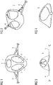
- FIG 1 - 4 show a faceblank 5.
- the shape of the faceblank 5 defines a number of filter openings 2, 3, 4, most advantageously a right-hand side opening 2, a left-hand side opening 3 and a bottom opening 4.
- the faceblank 5 further comprises a head harness 6 or a fastening for a head harness 6 and is characterised in that the filter openings 2, 3, 4 have been implemented to comprise a tongue 7, most advantageously so that the edge of each opening 2, 3, 4 is composed of a tongue.
- FIG 2 shows a fastening 6 for a head harness: the free end of the fastening 6 is bent towards the faceblank 5 and fastened in a form-restricted manner by taking a knob or bulge into a slot, in which case the fastening 6 forms a loop or eyelet.
- the knob or bulge relieves the pressure exerted by the fastening 6 on the face, and the loop or eyelet can be implemented to be made by just one hand.
- the faceblank 5 is fastened into place on the user's head so that a band (in particular a rubber band) or similar is fastened to the loops or eyelets, by means of which band or similar the faceblank 5 is tightened against the user's face.
- the faceblank 5 can comprise a mechanism that has been moulded to be most advantageously of uniform material, most preferably by the same moulding method (such as injection moulding) with which the faceblank 5 has been moulded, for example protrusions for the fastening of the head harness 6 (such as bands, in particular rubber bands).
- the faceblank 5 is manufactured most advantageously to be reusable so that replaceable filters 10 are installed in it.
- the faceblank 5 consists of a piece which has the shape of a so-called half an avocado and which imitates the shape of the face.
- the material used in the faceblank 5 is most advantageously of elastomer (silicone, polyurethane etc.), but inelastic materials are also possible.
- the filter openings 2, 3, 4 have been implemented to comprise a tongue 7, most advantageously so that the edge of each opening 2, 3, 4 is composed of a tongue 7.
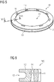
- FIG 5 shows a filter 10.
- Each filter comprises a filter part 11 and a frame 12 that encircles the filter part 11, in which frame 12 the outer edge has been implemented to comprise a groove 13 - most advantageously so that the outer edge of each frame 12 consists of a groove 13 - so that the filters 10 are fastenable to the filter openings 2, 3, 4 of the faceblank 5 by means of a tongue-and-groove connection, in which case the tongue 7 and groove 13 form an air-tight tongue-and-groove connection.
- the implementation of the frame 12 of the filter 10 and the groove is shown in section VI-VI shown in FIG 6 .
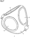
- FIG 7 shows a respiratory protective device or face mask hygiene product 1, where filters 10 have been placed into place in the filter openings 2, 3, 4 located in the faceblank 5.
- the respiratory protective device 1 or face mask hygiene product 1 can, in addition to the filters or instead of some filter 10, comprise an exhalation valve adapted in one of the filter openings 2, 3, 4 and connected to the surrounding frame 12.
- edges of the filter openings 2, 3, 4, in other words the tongue 7, are so shaped that they sit in an air-tight manner in the groove 13 of the frame 12 of the filters 10 and so that the filters 10 with their integrated frame are replaceable.
- the targeted service life of the faceblank 5 is most advantageously at least 100 times of use (number of replacements of filters), which enables a smaller price per time of use of the faceblank.
- the frame 12 of the filters 10 is primarily of hard plastic.
- Polypropylene for example, guarantees the recyclability of the filters 10 due to a homogeneous composition.
- the filters 10 can be manufactured with different filtering classes, colours and additional properties.
- the filter part 11 consists of one or more similar or different filter material layers, which are either textile and/or non-woven fabric. Polypropylene-based, electrically-charged filtering material as well as surface layers that protect the actual filter layer are most advantageously used. Just textile without filtering properties can also be used in the frame 12 for so-called everyman's masks.
- an exhalation valve can be connected to one or more frames 12, for example for the building industry.
- the filters 10 are printed, most advantageously in the manufacturing process, with their filtering class, manufacturing and expiration date as well as the place of manufacture and (within the European Economic Area) the CE marking as well as possibly also the identification of the notified body, most likely using laser technology or pad printing (Tampondruck in German). After this, the filters 10 are packed in air-tight packaging.
- the respiratory protective device or face mask hygiene product 1 is implementable as CE-certified personal protective equipment in accordance with the EU standard EN140:1998 (including corrections AC:1999).
- the filters 10 are detachable.
- the respiratory protective device or face mask hygiene product 1 is implementable, if desired, also as CE-certified personal protective equipment in accordance with the EU standard EN149:2009. In this case, the filters 10 would not be detachable.
- the targeted filtering classes include (FFP1-FFP3 A1 NR), where: FFP1-FFP3 denotes the filtering level or class, A1 a reusable frame, and NR a Not Reusable filter.
- FFP1-FFP3 denotes the filtering level or class
- A1 a reusable frame
- NR a Not Reusable filter.
- Type IIR is a classification that enables working in surgical conditions, and its manufacture requires the manufacturing permit of a medical device. This is why the respiratory protective device or face mask hygiene product 1 can also be implemented in accordance with "European Medical Device Directive (93/42/EEC) and EN 14683:2005 Type IIR for use as a surgical mask”.
- the purpose of the best possible, tight fitting of the respiratory protective device or face mask hygiene product 1 against different kinds of faces in various (working) positions is to achieve a by-pass flow of a maximum of 0 - 1%.
- By-pass flow refers to the air that flows/escapes in an uncontrolled manner between the respiratory protective device or face mask hygiene product and the face when breathing out or in. This can be affected directly by balancing the pressure difference by means of a maximal filtering area. The smaller the filter area, the greater the need for pressure balancing (leak) between the edges of the respiratory protective device or face mask hygiene product 1 and the face, and the smaller the volume of air that travels per a square centimetre of the filter.
- the changing of the filter material or the selection of the frame material or the stiffness of the faceblank 5 can be used for having an effect that reduces the filtering level, if that is to be desired.
- the goal in the manufacture of the respiratory protective device or face mask hygiene product 1 is to have as few work stages as possible and an as high processing degree per work stage as possible. Primarily, this is sought by using the injection moulding technique and by integrating functions in the moulds.
- the tightening mechanism according to the first embodiment consists of a part in the shape of the letter H, where the "transverse line of the letter H" is of the same material as the frame of the mask, while the "vertical lines of the letter H” are most advantageously of (hard) plastic.
- Plastic is used so that elastomer would not lose its restoration ability too rapidly by the rubbing and pull of the rubber bands.
- Other alternatives for use as the fastening method are also examined. When this is being written, the most advantageous alternative would seem to be that the faceblank 5 is implemented as a one-part component.
- the primary purpose is to guarantee the fastening of the respiratory protective device or face mask hygiene product 1 behind the head with, for example, two rubber bands, the tightness of which can be adjusted. Moreover, it is important that the rubber band is disposable, not reusable, due to hygiene reasons. The rubber band is discarded/recycled when the filters 10 are replaced, and new rubber bands are always delivered in the packaging of the filters 10 for the respiratory protective device or face mask hygiene product.
- the method described here is used advantageously for the manufacture of filters 10.
- the method can be used for the manufacture of even other reinforced textile parts, nonwoven fabric parts or their combination parts.
- FIG 12 shows the mould 100 in the closed position.
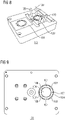
- FIG 8 and 9 show the first part 101 of the mould 100
- FIG 10 and 11 show the second part 102 of the mould 100.
- FIG 12 also shows a web 1200, which is fed into the mould 100, where the filter part 11 is first cut (die cut) so that it remains joined to the web 1200 by the uncut parts 1201, and then the frame 12 is moulded.
- the arrow shown in FIG 12 describes the direction in which the web 1200 is moved.
- the filters 10 remain joined to the remaining web 1200', to which the filters 10 have been moulded. It is thus possible to use the remaining web 1200' in a way as a conveyor belt in serial production or as part of a conveyor belt to carry the filters 10 forward. This is also indicated in FIG 14 .
- FIG 13 shows the cutting taking place in the first part 101 of the mould 100 in the drawing on the left, and the positioning and moulding taking place after transfer on the right.
- the positioning and moulding are described in more detail below.
- FIG 15 shows one round filter 100 joined to the web.
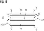
- FIG 16 - 18 show an embodiment of the parallel manufacture of several filters 10, implemented on a corresponding manufacturing line as that shown in FIG 15 .
- the filters 10 form a filter set 10', where the filters 10 are joined to each other as a usage set, for example, which contains all the filters 10 needed for a use of one faceblank 5.
- packing is as easy as possible, and one filter set 10' would follow each other throughout the process from the beginning to the end, for example to marking (it has been described above that laser marking, for example, could be used) and packaging.
- FIG 16 shows a filter set 10' viewed from above in a mould (more precisely: in the cutting part of a mould) before the moulding of the frames 12.
- the uncut parts 1201 of the web 1200 and on the other hand the parts of the die cutting press 105 have been marked in FIG 16 .
- the parts of the die cutting press 105 surround the uncut parts and, on the other hand, form channels, in which the uncut parts 1201 remain.
- channels can be formed between individual filters 10 in order to keep the filters 10 joined to each other. In the above-described manner, this facilitates the handling and packing of the filters 10.
- FIG 17 shows correspondingly a complete set 10'.
- the filter part 11 formed from the web 1200 or webs is indicated with line shadowing.
- the part of the web 1200 that remains inside the frame 12 - which part does not constitute the filter part 11 - has been indicated with line shadowing in broken line. Even though this part of the web 1200 does not constitute the filter part 11, it is needed in accordance with what has been described above to tighten the filter part 11 in the frame 12.
- the uncut part 11 has also been formed from the web 1200. However, it has not been line-shadowed in FIG 17 , because they do not constitute a functional part of the filter 10 - said parts can be torn off, for example, before installing the filter 10 to the faceblank 5.
- the mode of operation described here enables the foldability of the filter set 10' in a handy manner.
- the filters 10 are delivered so that they are packed in a bag as a set of one mask.
- Hand tissues (one or more) intended for the disinfection of hands / the mask are (likely) also delivered with the bag.
- the first hand tissue is intended for the disinfection of hands, the second for the disinfection of the frame of the mask.
- Used filters 10 are popped out or pressed out of the faceblank 5 first and recycled/discarded. After this, hands are disinfected and then the faceblank 5.
- New filters 10 are detached from each other and placed one by one in the filter openings 2, 3, 4 of the faceblank 5 by stretching the frame of the faceblank 5 a little so that the tongues 7 in the faceblank 5 can settle into the groove 13 in the frame 12.
- the frame of the faceblank 5 is shaped so that it is easily cleanable and the surface is smooth.
- the natural shape of the faceblank 5 enables, for example, the flowing of washing water away from over the mask.
- the faceblank 5 can also be cleaned with a cleaning tissue intended for this purpose, using a disinfectant or detergent.
- the frame of the faceblank 5 is intended to be dishwasher proof.
- FIG 15 shows a possible production line.
- the filter part 11 of the filters 10 or more generally that part of the combination part that is to be reinforced is most advantageously stored in a number of reels 202, 203.
- Some of the reels can be main reels 202 and some auxiliary reels 203.
- the reels 202, 203 are most advantageously brakable, for example by means of reel brakes 201.
- Guide rolls 204 guide the material taken from the reels 202, 203 to become a combined web 205, which is guided into an injection moulding machine 206, which contains a mould 100.
- FIG 15 shows the corresponding parts of the mould 100: the moving side 207 of the mould (first part 101 of the mould) and the non-moving side 208 of the mould (second part 102 of the mould). The moving side of the mould 100 closes against the solid side on the side of the extrusion screw and the extrusion screw feeds the moulding compound into the mould 100.
- the moulded pieces 210 are, for example, filters 10.
- Pincher rolls 211 pull the web. Turn rolls 212, 213 guide the webs for marking, for example to a laser marking device 214. Laser-marked pieces are detached from the web on a detaching device 216 and the waste web is removed on a removal device 217. A conveyor belt 218 carries the marked pieces to packing equipment 219. After packing, the packed products 220 are ready for further delivery.
- the production line is most advantageously located in a clean room.
- the production line is implementable as relatively short and/or in small size, which enables the use of a smaller clean room.
- the faceblank 5 becomes tighter for faces of various sizes and shapes when it includes a number of nose seals 31.
- FIG 19 and 20 show a faceblank 5 equipped with nose seals 31.
- the nose seals 31 are implemented most advantageously so that they are integrated into the faceblank 5, for example as fin-like protrusions.
- a nose seal 31 implemented as fin-like protrusions presses against the user's face. The inventors have noticed that it reduces the pressure exerted by the respiratory protective device / face mask hygiene product 1 on the face, because the nose seal 31 distributes the pressing directed at the face over a larger area. In this way, it is possible to improve the usage comfort of the respiratory protective device / face mask hygiene product.
- the shape of the nose seal 31 forms a hinter-cut in the mould. This is not a problem if the mould is implemented in two parts. In this case, however, a seam remains at the joining joint of the moulds, which seam tends to feel uncomfortable, because there are a lot of nerves in the skin of the face.
- the machining of nose seals 31 in a single-part mould using a CNC machine, such as by milling, is not possible due to the moulding shape required from the mould, because the frame of the faceblank 5 would prevent the formation of a recess required for the nose seal 31.
- an electrode 40 that contains the moulding pattern 41 of the nose seal is used in the manufacture of the mould of the faceblank 5.
- the line L marked in FIG 21 describes the edge of the moulding pattern 41.
- the mould machined using a CNC machine (for example, an aluminium mould) is modified after machining by implementing, most advantageously by electric discharge machining, a moulding shape 58 in accordance with the moulding pattern 41 by means of an electrode and, for example, an EDM machine.
- FIG 22 shows a half 50' of the mould of the faceblank 5 before the implementation of the moulding shape 58 of the nose seal, where the electrode in accordance with FIG 21 is already in place.
- An EDM machine forms the moulding shape 58 in the mould half 50 by means of electric discharge machining in the manner shown in FIG 23 .
- FIG 23 shows a complete mould half 50 of the faceblank 5, into which mould half 50 the moulding shape 58 has been formed for the formation of the nose seal 31.
- This mould half 50 is for the inner side of the faceblank 5.
- Another mould half is needed for the outer side of the faceblank 5, and this is implemented in a corresponding manner.
- the mould halves are placed against each other, and material, such as silicone, used for the moulding of the faceblank 5, is injection-moulded into the mould, in other words into the intermediate space defined by the mould halves.
Landscapes
- Engineering & Computer Science (AREA)
- Health & Medical Sciences (AREA)
- General Health & Medical Sciences (AREA)
- Manufacturing & Machinery (AREA)
- Mechanical Engineering (AREA)
- Physical Education & Sports Medicine (AREA)
- Textile Engineering (AREA)
- Emergency Management (AREA)
- Business, Economics & Management (AREA)
- Life Sciences & Earth Sciences (AREA)
- Zoology (AREA)
- Pulmonology (AREA)
- Respiratory Apparatuses And Protective Means (AREA)
- Filtering Materials (AREA)
Abstract

Description
- The invention is related to respiratory protective devices and face mask hygiene products and their manufacture on one hand and to the manufacture of reinforced textile parts, nonwoven fabric parts or their combination parts on the other hand.
- Since February/March 2020, many states in all parts of the world have decided to exceptionally impose restrictions on the freedom of movement of people as the COVID-19 epidemic turned into a pandemic. The use of respiratory protective devices has also been made mandatory in some countries, especially in public places or public transport.
- As shops ran out of industrially-manufactured respiratory protective devices at times, instructions have been shared on the Internet on how to make textile face masks from fabric. Industrially-manufactured respiratory protective devices made from non-woven fabric are in practice the most commonly used type. On the basis of waste accumulating on streets, it also appears that some people have ended up using surgical face masks, possibly partly because there has only been a limited supply of respiratory protective devices in places.
- A surgical face mask is a medical device intended to protect the patient from pathogens present in the exhalation air of medical staff. A surgical face mask does not protect its user from airborne diseases.
- Respiratory protective devices in the area of the European Union must fulfil the requirements of the personal protective equipment regulation (EU) 2016/425. As indication of the fulfilment of the requirement, the protective equipment must bear the CE marking. Respiratory protective devices include medical face masks, and on the other hand different types of respiratory protective devices intended for various purposes.
- Medical face masks are used, for example, and in particular when treating a patient who has an airborne disease. In this case, it is typically sufficient that the respiratory protective device filters aerosols with a size of at least 5 µm. The properties required from medical face masks have been defined in the European standard EN 14683:2019 + AC:2019.
- The technical requirements of respiratory protective devices and of filtering half masks that protect from particles have been presented in the European standard EN 149:2009 + A1:2009. The main filter or filters of such respiratory protective devices and half masks constitute an inseparable part of the device. The classes of such respiratory protective devices and half masks include FFP1, FFP2, FFP3, for example.
- The technical requirements of respiratory protective devices equipped with a replaceable filter and of quarter and half masks that filter particles have been presented in the European standard EN 140:1998 and in correction AC:1999 of said standard.
- As an example, the Finnish Institute for Health and Welfare, which is an independent research agency operating under the Finnish Ministry of Social Affairs and Health, states practical protection factors for respiratory protective devices on its website (in Finnish) (https://thl.fi/fi/web/infektiotaudit-ja-rokotukset/taudit-ja-torjunta/infektioiden-ehkaisy-ja-torjuntaohjeita/hengityksensuojaimien-kaytto).
- The practical protection factor of respiratory protective devices means how many times over the protective device reduces the aerosol content of the breathed air with 95% of the persons, provided that the protective device sits well and that the user has been instructed to use the protective device. The practical protection factor of a filtering half mask, the efficiency class of which is FFP1 (EN 149), is 4. The practical protection factor of a filtering half mask, the efficiency class of which is FFP2 (EN 149), is 10. The practical protection factor of a filtering half mask, the efficiency class of which is FFP 3 (EN 149), is 20.
- Correspondingly, the practical protection factor of half masks equipped with a P3 filter (EN 140 and EN 143) is 20.
- On the other hand, it is known in practice that respiratory protective devices (EN 140) used against biohazards and equipped with a P3 filter (EN 143), for example half masks or quarter masks, can achieve a filtering efficiency of up to more than 99.95% (see Table A, 3M Company Personal Safety Division publication "Respiratory Protection for Airborne Exposures to Biohazards", #174 in series Technical Data Bulletin, ).
- Even though it might be possible to achieve a considerably better filtering result in favourable circumstances with a respiratory protective device equipped with a replaceable filter than with a respiratory protective device in accordance with the European standard EN 149:2009 or with a filtering half mask that protects against particles, respiratory protective devices equipped with a replaceable filter are relatively complex and their purchase price is relatively expensive.
- The objective according to the first aspect of the invention is to simplify the structure of respiratory protective devices equipped with a replaceable filter. This objective is solvable by means of a faceblank according to
claim 1, by means of a respiratory protective device or face mask hygiene product according toclaim 6, and also by means of a filter according to claim 9. - The purpose of the objective parallel to the first objective of the invention is to enable a manner of protection against airborne diseases, such as a coronavirus infection, that is provided to the general public and that is better than that of even disposable respiratory protective devices in favourable circumstances by means of a face mask hygiene product manufactured in a simple manner on an industrial scale. This objective is solvable by means of a faceblank according to
claim 1 or by means of a respiratory protective device or face mask hygiene product according toclaim 6, by using a filter according to claim 9 in these. - The third objective of the invention alternative to or supplementary to the first and second objectives is to simplify the manufacture of a reinforced textile part, nonwoven fabric part or their combination part. This objective can be solved by means of a method according to claim 16.
- The dependent claims describe the preferred embodiments of the faceblank, respiratory protective device / face mask hygiene product, filter and method.
- One of the items of the invention is a respiratory protective device and its filter, or alternatively a face mask hygiene product and its filter. The respiratory protective device or face mask hygiene product can also be a medical device.
- The respiratory protective device or face mask hygiene product is most advantageously a half mask or quarter mask, particularly advantageously, for example, one specified in the European standard EN 140:1998. Alternatively, the respiratory protective device can be an unassisted filtering device. The names of the parts of the half mask and quarter mask have been presented in the European standard EN 134:1998 under item 3.1.2, and the names of the parts of the unassisted filtering device have been presented under item 3.2.1 of the same standard.
- In the faceblank according to the first and second aspects of the invention for a respiratory protective device or face mask hygiene product, the shape of the faceblank defines a number of filter openings. Moreover, the faceblank comprises a head harness or fastening for a head harness. The filter openings have been implemented to comprise a tongue, most advantageously so that the edge of each opening is formed by a tongue.
- The respiratory protective device or face mask hygiene product according to the first and second aspects of the invention comprises a faceblank described in the preceding paragraph and a number of replaceable filters adapted in the filter openings of the faceblank, each of which filters comprises a filter part and a frame that encircles the filter part. In the frame, the outer edge has been implemented to comprise a groove - most advantageously so that the outer edge of each frame consists of a groove - so that the filters are fastenable to the filter openings of the faceblank by means of a tongue-and-groove connection, in which case the tongue and groove form an air-tight tongue-and-groove connection.
- This gives an opportunity to implement the respiratory protective device or face mask hygiene product in a simple configuration. Firstly, it is not necessary to implement separate equipment connectors in the faceblank, and since a filter housing can also be omitted from the faceblank, it is possible to technically implement the faceblank in a simple manner.
- Correspondingly, due to the manner of execution of the tongue-and-groove connection, the structure of the replaceable filters can also be kept simple and the replaceability of the filters can be implemented in a simple manner; however, so that the replaceable filters are gas-tight.
- The selected manner of execution of the tongue-and-groove connection also has its significance: When the faceblank is to be reusable and the filters are to be mainly disposable, easy cleanability requires that the faceblank does not have any recesses or slots that might gather dirt or that would be difficult to clean or dry. Easy cleanability and dryability are accomplished precisely because the tongue encircles the filter holes of the faceblank all around, in which case it is possible to implement the filter holes without inward-turned recesses or slots.
- According to an advantageous aspect, the faceblank comprises mechanisms or protrusions that have been moulded to have a uniform material - most advantageously by injection moulding - for the fastening of the head harness. Due to the uniform material, a sufficient strength is achieved in the structure so that the head harness of the respiratory protective device or face mask hygiene product remains fastened to the respiratory protective device or face mask hygiene product also when the going gets rough.
- According to an advantageous aspect, the protrusions have pins for band fastening. In this case, the head harness can be implemented well as a band, such as a rubber band. This enables the reusability of the faceblank in a hygienic manner also if the next user of the faceblank is a different person. The faceblank can be washed after use most advantageously in an ordinary washing machine, for example. When the head harness (in other words the old band) is removed and discarded before washing and when the head harness (in other words the new band) is fastened after washing and drying, it is possible to ensure the hygiene of the part that comes against the hair and more generally against the back part of the head of the user of the head harness. The fastening of the head harness (in other words of the bands) to the faceblank can be implemented in a simple manner by means of pins.
- According to an advantageous aspect, the head harness is implemented with replaceable bands, which are most advantageously rubber bands or comprise rubber bands. The replaceable bands are fastened particularly advantageously in the above-described manner to the pins of the faceblank. The term "rubber band" refers here and below to an elastic band, in other words elastic stretchability is a requirement, but it is not a requirement that the rubber band would contain rubber. As an example, medical rubber band does not contain rubber.
- According to one advantageous aspect, the faceblank comprises a number of nose seals implemented in the faceblank in a materially uniform manner. There are most advantageously two nose seals, but the faceblank can also be implemented easily with one nose seal. The nose seal/seals has/have been formed by moulding by means of one-part mould halves placed opposite to each other, in which mould halves the moulding shape of the nose protrusion has been implemented by electric discharge machining. It is thus possible to implement the faceblank for faces and noses of several sizes so that it fits better, in other words is tighter. Moreover, the inventors have discovered that the nose seal/seals reduces/reduce the pressure exerted by the faceblank on the face, thus improving the usage comfort of the faceblank.
- Furthermore, the filters can be according to one or more what is presented below. In addition to this or instead of this, the filters can be manufactured by using a method according to any of the claims 16 - 21.
- The respiratory protective device or face mask hygiene product can further comprise an exhalation valve adapted in one of the filter openings and connected to the surrounding frame. This enables the staying of the respiratory protective device or face mask hygiene product more tightly against the face also during exhalation, especially when the filters are clogged to some extent, in which case the respiratory protective device or face mask hygiene product would be pushed farther away from the face as a result of the pressure difference caused by exhalation. On the other hand, depending on the manner of execution, the valve can also relieve exhalation, which has significance in physically strenuous work, for example.
- The filter for the respiratory protective device or face mask hygiene product comprises a filter part that contains textile and/or non-woven fabric, and a frame that encircles it. The frame has been fastened by moulding - most advantageously by using the injection moulding method - directly to the filter part.
- According to an advantageous aspect, the filter part has been stretched when the moulding of the frame begins. In this way, it is possible to reduce or even avoid the flutter of the filter part during inhalation and exhalation. Some people think that the flapping sound created by the flutter of the filter part is annoying.
- The filter most advantageously comprises several layers. In this way, it is possible, depending on the manner of execution, to improve the filtering efficiency or protect the filter layer, which is possibly more sensitive to contact, and to hence improve the operating reliability of such a more delicate filter layer. In particular for this reason, the filter can be implemented so that it comprises at least one filter layer and a number of coating layers, which protect the filter layer, arranged on its one side or both sides. This is a particularly advantageous mode of operation when the filter layer comprises electrically-charged filtering material (most advantageously a material based on polypropylene or a material containing polypropylene). In addition to or instead of electrically-charged filtering material, it is possible to use mechanical filters and/or filters that contain activated carbon.
- The inventors have discovered that the flapping sound described in the preceding paragraph may appear with two filter material layers, but the flapping sound no longer appeared in test items that comprised at least three filter material layers.
- In the other extreme mode of operation, the filter part of the filter comprises textile only in order to implement the filter used in a face mask hygiene product (in other words in the so-called everyman's mask). The filter material used can also be mechanically-filtering layers and activated carbon, for example (or material that contains activated carbon).
- In the method for the manufacture of a reinforced textile part, nonwoven fabric part or their combination part, a part to be reinforced that comprises textile, non-woven fabric or both of these is placed in a mould while stretched and stretching is maintained at the same time as a frame, which encircles the part, is moulded - most advantageously by injection moulding - into the mould. In this way, it is possible to omit a possible stiffening structure, which would otherwise be required in the part, from the part.
- Stretching is most advantageously carried out by pre-tensioning the part to be reinforced before closing the mould, and by using the mould to ensure that the pre-tensioning is maintained when the mould closes. Since the mould must close tightly in injection moulding, for example, the maintaining of the stretching or pre-tensioning due to the mould when the mould closes can be ensured in the handiest manner precisely by means of the mould.
- In an advantageous embodiment of the method, the part to be reinforced is separated from a larger strip (in other words from a web) of textile, non-woven fabric or both by die cutting before moulding - most advantageously in a cutting part implemented in the mould - however, so that the part to be reinforced remains in a material connection with the larger strip, in other words some of the perimeter or circumference of the part to be reinforced is not die cut.
- The larger strip is most advantageously a textile or non-woven fabric coming from a reel, or a number of textiles and/or non-woven fabrics coming from separate reels. In this way, it is possible to implement a manufacturing line whose automation is more advantageously implementable.
- Most advantageously, the outside remains of textile or non-woven fabric in the part to be reinforced that are in a material connection are transferred in the feed direction from an opening mould without breaking off. In this way, it is possible to transfer the reinforced parts, which come out of the mould, easily away from the mould, which increases the safety of operation, because the moulds used in moulding are typically hot and the opening/closing mould is dangerous.
- The part to be reinforced that comprises textile, non-woven fabric or both of these most advantageously comprises several material layers. In an advantageous embodiment of the method, material layers are pressed against each other during moulding, most advantageously by means of pins or similar arranged in the mould. In this way, the material layers can be made into a denser package also at the location of the frame, which enables an increase in the strength of the part to be reinforced. The moulding compound that is squeezed between the material layers, especially in thin layers, may have an impact whereby an individual material layer comes off the frame even at a relatively small force.
- The pins or similar are most advantageously located in the frame area. In this way, it is possible to use the pins or similar also after moulding for pushing the reinforced part out of the mould after the mould has been opened.
- In an advantageous embodiment of the method, several parts to be reinforced are moulded in parallel and transferred in the manufacturing process while in a material connection to each other, in other words without being detached from one another. This enables an increase in the capacity of serial production.
- The faceblank is most advantageously manufactured in single-component moulding (like the fastening of the head harness, which fastening is most advantageously implemented in a materially uniform manner in the faceblank, for example so that the faceblank and the fastening/fastenings is/are moulded at the same time). The head harness is most advantageously manufactured from a single material. In the filters, the filter part and the frame are most advantageously manufactured from the same (most preferably a single) material. By doing so, the components can be separated from each other for recycling in a highly simple manner.
- It is possible to advantageously use polypropylene in the filter part (as filter fabric/fabrics) and in the filter frame, for example, which enables the recycling of the filters as such when a potential risk of contamination has been taken care of. In this case, the filters can be utilised in energy use by combustion, for example. The filter part is best non-woven (for example polypropylene) and the frame is moulded and of hard plastic (for example polypropylene).
- In what follows, the implementation of the respiratory protective device or face mask hygiene product, faceblank, filter and on the other hand also of the method according to the invention is discussed in more detail by means of the embodiments presented in the enclosed drawings. Of the drawings:
- FIG 1 - 4
- show a faceblank;
- FIG 5
- shows a filter;
- FIG 6
- shows section VI-VI made at the frame of the filter of
FIG 5 ; - FIG 7
- shows a respiratory protective device or face mask hygiene product;
- FIG 8 - 9
- show a first part of a mould;
- FIG 10 - 11
- show a second part of a mould;
- FIG 12
- shows cutting and moulding with the mould closed, strip in closed mould;
- FIG 13 and 14
- show the mould opened after cutting and moulding, strip in opened mould;
- FIG 15
- shows equipment designed to implement the method;
- FIG 16
- shows three filters manufactured in parallel in a mould (more precisely: in the cutting part of mould);
- FIG 17
- shows a filter set, with three filters manufactured in parallel;
- FIG 18
- shows a filter set folded together;
- FIG 19 and 20
- show an advantageous embodiment of the faceblank;
- FIG 21
- shows an electrode for the formation of the moulding shape of the nose seal of the faceblank;
- FIG 22
- shows the electrode shown in
FIG 21 in its place in the mould; and - FIG 23
- shows a part of the mould of a faceblank with a nose seal.
- The same reference numbers refer to the same technical characteristics in all FIGs.
-
FIG 1 - 4 show afaceblank 5. The shape of thefaceblank 5 defines a number offilter openings hand side opening 2, a left-hand side opening 3 and abottom opening 4. Thefaceblank 5 further comprises ahead harness 6 or a fastening for ahead harness 6 and is characterised in that thefilter openings tongue 7, most advantageously so that the edge of eachopening -
FIG 2 shows afastening 6 for a head harness: the free end of thefastening 6 is bent towards thefaceblank 5 and fastened in a form-restricted manner by taking a knob or bulge into a slot, in which case thefastening 6 forms a loop or eyelet. The knob or bulge relieves the pressure exerted by thefastening 6 on the face, and the loop or eyelet can be implemented to be made by just one hand. Thefaceblank 5 is fastened into place on the user's head so that a band (in particular a rubber band) or similar is fastened to the loops or eyelets, by means of which band or similar thefaceblank 5 is tightened against the user's face. - The
faceblank 5 can comprise a mechanism that has been moulded to be most advantageously of uniform material, most preferably by the same moulding method (such as injection moulding) with which thefaceblank 5 has been moulded, for example protrusions for the fastening of the head harness 6 (such as bands, in particular rubber bands). - The
faceblank 5 is manufactured most advantageously to be reusable so thatreplaceable filters 10 are installed in it. - The
faceblank 5 consists of a piece which has the shape of a so-called half an avocado and which imitates the shape of the face. The material used in thefaceblank 5 is most advantageously of elastomer (silicone, polyurethane etc.), but inelastic materials are also possible. - The
filter openings tongue 7, most advantageously so that the edge of eachopening tongue 7. -
FIG 5 shows afilter 10. Each filter comprises afilter part 11 and aframe 12 that encircles thefilter part 11, in whichframe 12 the outer edge has been implemented to comprise a groove 13 - most advantageously so that the outer edge of eachframe 12 consists of a groove 13 - so that thefilters 10 are fastenable to thefilter openings faceblank 5 by means of a tongue-and-groove connection, in which case thetongue 7 and groove 13 form an air-tight tongue-and-groove connection. The implementation of theframe 12 of thefilter 10 and the groove is shown in section VI-VI shown inFIG 6 . -
FIG 7 shows a respiratory protective device or facemask hygiene product 1, where filters 10 have been placed into place in thefilter openings faceblank 5. The respiratoryprotective device 1 or facemask hygiene product 1 can, in addition to the filters or instead of somefilter 10, comprise an exhalation valve adapted in one of thefilter openings frame 12. - The edges of the
filter openings tongue 7, are so shaped that they sit in an air-tight manner in thegroove 13 of theframe 12 of thefilters 10 and so that thefilters 10 with their integrated frame are replaceable. - It is possible to use various replaceable moulding parts to mould symbols, logos or emblems used in marketing or communications in the
faceblank 5. Instead of this or in addition to this, it is possible to print, press or fasten symbols, logos or emblems in thefaceblank 5. - The targeted service life of the
faceblank 5 is most advantageously at least 100 times of use (number of replacements of filters), which enables a smaller price per time of use of the faceblank. - The
frame 12 of thefilters 10 is primarily of hard plastic. Polypropylene, for example, guarantees the recyclability of thefilters 10 due to a homogeneous composition. - The
filters 10 can be manufactured with different filtering classes, colours and additional properties. Thefilter part 11 consists of one or more similar or different filter material layers, which are either textile and/or non-woven fabric. Polypropylene-based, electrically-charged filtering material as well as surface layers that protect the actual filter layer are most advantageously used. Just textile without filtering properties can also be used in theframe 12 for so-called everyman's masks. - Instead of the filter material or in addition to the filter material, an exhalation valve can be connected to one or
more frames 12, for example for the building industry. - The
filters 10 are printed, most advantageously in the manufacturing process, with their filtering class, manufacturing and expiration date as well as the place of manufacture and (within the European Economic Area) the CE marking as well as possibly also the identification of the notified body, most likely using laser technology or pad printing (Tampondruck in German). After this, thefilters 10 are packed in air-tight packaging. - The respiratory protective device or face
mask hygiene product 1 is implementable as CE-certified personal protective equipment in accordance with the EU standard EN140:1998 (including corrections AC:1999). In this case, thefilters 10 are detachable. - Alternatively, the respiratory protective device or face
mask hygiene product 1 is implementable, if desired, also as CE-certified personal protective equipment in accordance with the EU standard EN149:2009. In this case, thefilters 10 would not be detachable. - The targeted filtering classes include (FFP1-FFP3 A1 NR), where: FFP1-FFP3 denotes the filtering level or class, A1 a reusable frame, and NR a Not Reusable filter. Moreover, when the frame of the mask if water-proof (primarily based on elastomer), splash resistance can be added to the filters, too, in which case the additional class Type IIR can be sought for the type approval of the mask. Type IIR is a classification that enables working in surgical conditions, and its manufacture requires the manufacturing permit of a medical device. This is why the respiratory protective device or face
mask hygiene product 1 can also be implemented in accordance with "European Medical Device Directive (93/42/EEC) and EN 14683:2005 Type IIR for use as a surgical mask". - The purpose of the best possible, tight fitting of the respiratory protective device or face
mask hygiene product 1 against different kinds of faces in various (working) positions is to achieve a by-pass flow of a maximum of 0 - 1%. By-pass flow refers to the air that flows/escapes in an uncontrolled manner between the respiratory protective device or face mask hygiene product and the face when breathing out or in. This can be affected directly by balancing the pressure difference by means of a maximal filtering area. The smaller the filter area, the greater the need for pressure balancing (leak) between the edges of the respiratory protective device or facemask hygiene product 1 and the face, and the smaller the volume of air that travels per a square centimetre of the filter. - After the optimum solution, the changing of the filter material or the selection of the frame material or the stiffness of the
faceblank 5 can be used for having an effect that reduces the filtering level, if that is to be desired. - The goal in the manufacture of the respiratory protective device or face
mask hygiene product 1 is to have as few work stages as possible and an as high processing degree per work stage as possible. Primarily, this is sought by using the injection moulding technique and by integrating functions in the moulds. - Manufacturing process of the tightening mechanisms of the rubber bands in the moulding process.
- The tightening mechanism according to the first embodiment consists of a part in the shape of the letter H, where the "transverse line of the letter H" is of the same material as the frame of the mask, while the "vertical lines of the letter H" are most advantageously of (hard) plastic.
- Plastic is used so that elastomer would not lose its restoration ability too rapidly by the rubbing and pull of the rubber bands. Other alternatives for use as the fastening method are also examined. When this is being written, the most advantageous alternative would seem to be that the
faceblank 5 is implemented as a one-part component. - The primary purpose is to guarantee the fastening of the respiratory protective device or face
mask hygiene product 1 behind the head with, for example, two rubber bands, the tightness of which can be adjusted. Moreover, it is important that the rubber band is disposable, not reusable, due to hygiene reasons. The rubber band is discarded/recycled when thefilters 10 are replaced, and new rubber bands are always delivered in the packaging of thefilters 10 for the respiratory protective device or face mask hygiene product. -
- 1. When the mould 100 (frame mould) is open, two plastic lines are pushed into place from reels on both sides of the upcoming respiratory protective device or face mask hygiene product (total quantity: four) (upcoming vertical lines of the letter H) .
- 2. When the
mould 100 closes, themould 100 cuts the vertical lines of the letter H to their dimension and squeezes their ends tightly against the moulding. - 3. Molten frame compound is injected into the
closed mould 100, into the fastening mechanism of the faceblank 5 (frame) of each respiratory protective device or facemask hygiene product 1 and at the same time hence into the fastening mechanism of the transverse line of the letter H. - 4. The mould opens and ejectors drop a completed faceblank 5 (frame) of the respiratory protective device or face
mask hygiene product 1 further to the process. - 5. Repeat.
- The method described here is used advantageously for the manufacture of
filters 10. In addition to this or instead of this, the method can be used for the manufacture of even other reinforced textile parts, nonwoven fabric parts or their combination parts. - A
mould 100, which contains afirst part 101 and asecond part 102, is most advantageously used in the method.FIG 12 shows themould 100 in the closed position.FIG 8 and 9 show thefirst part 101 of themould 100, andFIG 10 and 11 show thesecond part 102 of themould 100.FIG 12 also shows aweb 1200, which is fed into themould 100, where thefilter part 11 is first cut (die cut) so that it remains joined to theweb 1200 by theuncut parts 1201, and then theframe 12 is moulded. The arrow shown inFIG 12 describes the direction in which theweb 1200 is moved. In other words, thefilters 10 remain joined to the remaining web 1200', to which thefilters 10 have been moulded. It is thus possible to use the remaining web 1200' in a way as a conveyor belt in serial production or as part of a conveyor belt to carry thefilters 10 forward. This is also indicated inFIG 14 . -
- 1. A
filter web 1200 of a desired type (web refers to a continuous band), whichfilter web 1200 most preferably consists of at least one but most advantageously of several layers, a continuous filter material runs between thehalves mould 100. - 2. (IN STARTING) The
mould 100 closes for the first time while empty, in which case:- a. The
filter web 1200 becomes cut to the shape required by theframe 12 in the positioning so that it remains joined to thefilter web 1200 by the smalluncut parts 1201, or "trimmings", that are at an angle of, for example, 45 degrees, and can move with it to the next stage. In other words, thefilter part 11 is separated from thefilter web 1200 by means of incomplete cutting, most advantageously by pressing with adie cutting press 103 to thecounter piece 104 of the die cutting press, so that that part of theweb 1200 which corresponds to themiddle part 106 of the die cutting press forms thefilter part 11 remains joined to thefilter web 1200 while theparts 105 of the die cutting press cut, in joint action with theparts 107 of the counter piece of the die cutting press, the extra pieces out of thefilter web 1200 and filterpart 11. The "trimmings" are formed by the areas that remain between the parts of the die cutting press; there can be one or more such areas. - b. The extra pieces (in other words waste pieces) that have been cut off the
filter web 1200 and filterpart 11 are blown or sucked through the mould to be discarded. Air is blown or sucked through holes in the cutter, and the waste pieces fly or shift through the mould to be discarded.
- a. The
- 3. The
mould 100 closes for the second time for moulding, in which case:- a. The
cut filter web 1200 moves to the moulding point (described fromitem 2 onwards) and - b. the next point on the
filter web 1200 becomes cut simultaneously in positioning (described fromitem 4 onwards).
- a. The
- This process is illustrated by the opened
mould 100,FIG 13 , which shows the cutting taking place in thefirst part 101 of themould 100 in the drawing on the left, and the positioning and moulding taking place after transfer on the right. The positioning and moulding are described in more detail below. -
- 4. When the
mould 100 closes:- a. Guide pins 120 and guide
holes 121 close slides, which form a groove to a desired depth. In addition to or instead of guide pins, it is also possible to use other mechanic closing devices, such as cylinders. The cut, alignedfilter web 1200 remains in place in the mould at the desired "depth" with respect to the cross section of theframe 12. - b. Potential glides close, forming the rebate of the moulding when using a
groove 13 in theframe 12.
- a. Guide pins 120 and guide
- 5. Plastic is injected into the mould, in which case the
frame 12 is formed around thefilter web 1200.
In addition to this or as an alternative to this, an exhalation valve is moulded in thefilter 10 at the same time, either in thefilter part 11 or thefilter part 11 is replaced with it. - 6. When the moulding has cooled, the
mould 100 is opened and an ejector pin pushes thefilter 10 out of themould 100, transferring it forward in the process. - 7. The
web 1200 moves forward to the next process stage. - 8. Repeat (from
item 4 onwards). - It is possible to mould
several filters 10 simultaneously with the method, just as long as this is taken into consideration in the cutting andmoulding mould 100.FIG 15 shows oneround filter 100 joined to the web. -
FIG 16 - 18 show an embodiment of the parallel manufacture ofseveral filters 10, implemented on a corresponding manufacturing line as that shown inFIG 15 . In this case, thefilters 10 form a filter set 10', where thefilters 10 are joined to each other as a usage set, for example, which contains all thefilters 10 needed for a use of onefaceblank 5. In this case, packing is as easy as possible, and one filter set 10' would follow each other throughout the process from the beginning to the end, for example to marking (it has been described above that laser marking, for example, could be used) and packaging. -
FIG 16 shows a filter set 10' viewed from above in a mould (more precisely: in the cutting part of a mould) before the moulding of theframes 12. Theuncut parts 1201 of theweb 1200 and on the other hand the parts of thedie cutting press 105 have been marked inFIG 16 . The parts of thedie cutting press 105 surround the uncut parts and, on the other hand, form channels, in which theuncut parts 1201 remain. In the filter set 10', such channels can be formed betweenindividual filters 10 in order to keep thefilters 10 joined to each other. In the above-described manner, this facilitates the handling and packing of thefilters 10. -
FIG 17 shows correspondingly a complete set 10'. Thefilter part 11 formed from theweb 1200 or webs is indicated with line shadowing. The part of theweb 1200 that remains inside the frame 12 - which part does not constitute the filter part 11 - has been indicated with line shadowing in broken line. Even though this part of theweb 1200 does not constitute thefilter part 11, it is needed in accordance with what has been described above to tighten thefilter part 11 in theframe 12. Theuncut part 11 has also been formed from theweb 1200. However, it has not been line-shadowed inFIG 17 , because they do not constitute a functional part of the filter 10 - said parts can be torn off, for example, before installing thefilter 10 to thefaceblank 5. - The mode of operation described here enables the foldability of the filter set 10' in a handy manner.
- The
filters 10 are delivered so that they are packed in a bag as a set of one mask. Hand tissues (one or more) intended for the disinfection of hands / the mask are (likely) also delivered with the bag. The first hand tissue is intended for the disinfection of hands, the second for the disinfection of the frame of the mask. -
Used filters 10 are popped out or pressed out of thefaceblank 5 first and recycled/discarded. After this, hands are disinfected and then thefaceblank 5. -
New filters 10 are detached from each other and placed one by one in thefilter openings faceblank 5 by stretching the frame of the faceblank 5 a little so that thetongues 7 in thefaceblank 5 can settle into thegroove 13 in theframe 12. - The frame of the
faceblank 5 is shaped so that it is easily cleanable and the surface is smooth. - The natural shape of the
faceblank 5 enables, for example, the flowing of washing water away from over the mask. - The
faceblank 5 can also be cleaned with a cleaning tissue intended for this purpose, using a disinfectant or detergent. The frame of thefaceblank 5 is intended to be dishwasher proof. -
FIG 15 shows a possible production line. Thefilter part 11 of thefilters 10 or more generally that part of the combination part that is to be reinforced is most advantageously stored in a number ofreels main reels 202 and someauxiliary reels 203. Thereels reel brakes 201. Guide rolls 204 guide the material taken from thereels combined web 205, which is guided into aninjection moulding machine 206, which contains amould 100.FIG 15 shows the corresponding parts of the mould 100: the movingside 207 of the mould (first part 101 of the mould) and thenon-moving side 208 of the mould (second part 102 of the mould). The moving side of themould 100 closes against the solid side on the side of the extrusion screw and the extrusion screw feeds the moulding compound into themould 100. - After moulding, the moulded
pieces 210 are joined in the combinedweb 205. The mouldedpieces 210 are, for example, filters 10. - Pincher rolls 211 pull the web. Turn rolls 212, 213 guide the webs for marking, for example to a
laser marking device 214. Laser-marked pieces are detached from the web on adetaching device 216 and the waste web is removed on aremoval device 217. Aconveyor belt 218 carries the marked pieces to packingequipment 219. After packing, the packedproducts 220 are ready for further delivery. - The production line is most advantageously located in a clean room. By means of the above-described arrangement of the production line, the production line is implementable as relatively short and/or in small size, which enables the use of a smaller clean room.
- The
faceblank 5 becomes tighter for faces of various sizes and shapes when it includes a number of nose seals 31.FIG 19 and 20 show afaceblank 5 equipped with nose seals 31. For hygiene reasons, the nose seals 31 are implemented most advantageously so that they are integrated into thefaceblank 5, for example as fin-like protrusions. In practice, anose seal 31 implemented as fin-like protrusions presses against the user's face. The inventors have noticed that it reduces the pressure exerted by the respiratory protective device / facemask hygiene product 1 on the face, because thenose seal 31 distributes the pressing directed at the face over a larger area. In this way, it is possible to improve the usage comfort of the respiratory protective device / face mask hygiene product. - The shape of the
nose seal 31 forms a hinter-cut in the mould. This is not a problem if the mould is implemented in two parts. In this case, however, a seam remains at the joining joint of the moulds, which seam tends to feel uncomfortable, because there are a lot of nerves in the skin of the face. The machining of nose seals 31 in a single-part mould using a CNC machine, such as by milling, is not possible due to the moulding shape required from the mould, because the frame of thefaceblank 5 would prevent the formation of a recess required for thenose seal 31. - This is why it is more advantageous to implement the moulding shape required by the
nose seal 31 by electric discharge machining (EDM). For this purpose, anelectrode 40 that contains themoulding pattern 41 of the nose seal is used in the manufacture of the mould of thefaceblank 5. The line L marked inFIG 21 describes the edge of themoulding pattern 41. The mould machined using a CNC machine (for example, an aluminium mould) is modified after machining by implementing, most advantageously by electric discharge machining, amoulding shape 58 in accordance with themoulding pattern 41 by means of an electrode and, for example, an EDM machine. -
FIG 22 shows a half 50' of the mould of thefaceblank 5 before the implementation of themoulding shape 58 of the nose seal, where the electrode in accordance withFIG 21 is already in place. An EDM machine forms themoulding shape 58 in themould half 50 by means of electric discharge machining in the manner shown inFIG 23 . -
FIG 23 shows acomplete mould half 50 of thefaceblank 5, into whichmould half 50 themoulding shape 58 has been formed for the formation of thenose seal 31. Thismould half 50 is for the inner side of thefaceblank 5. Another mould half is needed for the outer side of thefaceblank 5, and this is implemented in a corresponding manner. In the moulding of thefaceblank 5, the mould halves are placed against each other, and material, such as silicone, used for the moulding of thefaceblank 5, is injection-moulded into the mould, in other words into the intermediate space defined by the mould halves. - The invention should not be understood to be limited only by the below claims, but the invention is to be understood to include all their legal equivalents and the combinations of the embodiments presented.
-
- 1
- respiratory protective device / face mask hygiene product
- 2, 3, 4
- filter opening
- 5
- faceblank
- 6
- head harness, fastening
- 7
- tongue
- 10
- filter (embodiment of respiratory protective device / face mask hygiene product), combination part (embodiment of method)
- 10'
- filter set
- 11
- filter part (embodiment of respiratory protective device / face mask hygiene product), part to be reinforced (embodiment of method)
- 12
- frame
- 13
- groove
- 14
- through hole
- 31
- nose seal
- 40
- electrode
- 41
- moulding pattern of nose seal in electrode
- 50'
- mould half for inner part of
faceblank 5, before the formation of moulding shape for nose seal - 50
- mould half for inner part of
faceblank 5, to which mould half the moulding shape for nose seal has been implemented - 51, 52, 53
- moulding shape for
filter openings - 56
- moulding shape for
head harness 6 - 57
- moulding shape for rebate
- 58
- moulding shape for nose seal, most advantageously implemented by means of electric discharge machining
- 100
- mould
- 101
- mould, first part
- 102
- mould, second part
- 103
- die cutting press
- 104
- counter piece of die cutting press
- 105
- parts of die cutting press
- 106
- middle part
- 107
- parts of counter piece of die cutting press
- 108
- area remaining between the parts of die cutting press
- 109
- outlet opening
- 120
- guide pin
- 121
- guide hole
- 201
- reel brakes
- 202
- main reels
- 203
- backup reels
- 204
- guide rolls
- 205
- combined web
- 206
- injection moulding machine
- 207
- moving side of mould
- 208
- non-moving side of mould
- 209
- extrusion screw
- 210
- moulded pieces joined to the web
- 211
- pincher rolls
- 212
- turn rolls (for example, 45 degrees)
- 213
- turn rolls (for example, 90 degrees)
- 214
- marking device for making a marking on the surface of the piece (for example, laser marking or pad printing device)
- 215
- marked piece
- 216
- detaching device / detaching of pieces from the web
- 217
- removal device / extra empty web removed
- 218
- conveyor belt
- 219
- packaging equipment
- 220
- packed product
- 1200
- web (in other words continuous band)
- 1200'
- web to which the
filters 10 have been moulded - 1201
- uncut part
Claims (22)
- A faceblank (5) for a respiratory protective device or face mask hygiene product (1), where the shape of the faceblank (5) defines a number of filter openings (2, 3, 4) and which further comprises a head harness (6) or fastening for a head harness (6) and is characterised in that the filter openings (2, 3, 4) have been implemented to comprise a tongue (7), most advantageously so that the edge of each opening (2, 3, 4) is composed of a tongue.
- A faceblank (5) according to claim 1, where the faceblank (5) comprises fastening mechanisms or protrusions that have been moulded to have a uniform material - most advantageously by injection moulding - to fasten the head harness (6).
- A faceblank (5) according to claim 2, where the protrusions have pins for rubber band fastening.
- A faceblank (5) according to any one of the preceding claims, where the head harness (6) has been implemented with replaceable bands, most advantageously rubber bands, which are fastened particularly advantageously to the pins of the faceblank (5) according to claim 3.
- A faceblank (5) according to any one of the preceding claims, which further comprises: a number of nose seals (31) implemented in the faceblank (5) with a uniform material, which nose seals (31) have been formed by moulding by means of one-part mould halves (50) placed against each other, in which mould halves (50) the moulding shape (58) of the nose seal (31) has been implemented by means of electric discharge machining.
- A respiratory protective device or face mask hygiene product (1), which comprises a faceblank (5) according to any one of the claims 1 - 5 and a number of replaceable filters (10) adapted in the filter openings (2, 3, 4) of the faceblank (5), each filter (10) of which comprises a filter part (11) and a frame (12) that encircles the filter part (11), in which frame (12) the outer edge has been implemented to comprise a groove (13) - most advantageously so that the outer edge of each frame (12) consists of a groove (13) - so that the filters (10) are fastenable to the filter openings (2, 3, 4) of the faceblank (5) by means of a tongue-and-groove connection, in which case the tongue (7) and groove (13) form an air-tight tongue-and-groove connection.
- A respiratory protective device or face mask hygiene product (1) according to claim 6, where at least some - most preferably all - of the filters (10) are also according to any one of the claims 9 - 15 and/or manufactured by using a method according to any one of the claims 16 - 21.
- A respiratory protective device or face mask hygiene product (1) according to claim 6 or 7, which further comprises an exhalation valve adapted in one of the openings (2, 3, 4) and connected to the surrounding frame (12).
- A filter (10) for a respiratory protective device or face mask hygiene product (1), which filter (10) comprises a filter part (11) that includes textile and/or non-woven fabric as well as a frame (12) that encircles it and where the frame has been fastened by moulding - most advantageously by using the injection moulding method - directly to the filter part (11).
- A filter (10) according to claim 9, where the filter part (11) has been stretched when the moulding of the frame (12) begins.
- A filter (10) according to claim 9 or 10, which filter (10) comprises several layers.
- A filter (10) according to claim 11, which filter (10) comprises at least one filter layer and a number of coating layers, which protect the filter layer, arranged on its one side or both sides.
- A filter (10) according to claim 12, where the filter layer comprises electrically-charged filtering material, which is most advantageously a material based on polypropylene or a material containing polypropylene, and/or a mechanical filter and/or a filter that contains activated carbon.
- A filter (10) according to claim 9 or 10, where the filter part (11) comprises textile only in order to implement the filter (10) used in the face mask hygiene product (1), in other words in the so-called everyman's mask.
- A filter (10) according to any one of the preceding claims 9 - 14, which filter (10) has been manufactured by using a method according to any of the claims 16 - 21.
- A method for the manufacture of a reinforced textile part, nonwoven fabric part or their combination part (10), characterised in that in the method a part to be reinforced (11), comprising textile, non-woven fabric or both of these, is placed into a mould (100) while stretched and stretching is maintained at the same time as a frame (12), which encircles the part (11), is moulded - most advantageously by injection moulding - into the mould (100).
- A method according to claim 16, where: the stretching is carried out by pre-tensioning the part to be reinforced (11) before closing the mould (100), and by using the mould (100) to ensure that the pre-tensioning is maintained when the mould (100) closes.
- A method according to claim 16 or 17, where the part to be reinforced (11) is separated from a larger strip, in other words from a web (1200, 205) of textile, non-woven fabric or both by die cutting before moulding - most advantageously in a cutting part implemented in the mould (100) - however, so that the part to be reinforced (11) remains in a material connection with the larger strip, in other words some of the perimeter or circumference of the part to be reinforced is not die cut.
- A method according to claim 18, where the larger strip (1200, 205) is a textile or non-woven fabric coming from a reel (202, 203) or a number of textiles and/or non-woven fabrics coming from separate reels (202, 203).
- A method according to claim 19, where the outside remains of textile or non-woven fabric in the part to be reinforced (11) that are in a material connection are transferred in the feed direction from an opening mould (100) without breaking off.
- A method according to any one of the claims 16 - 19, where: the part to be reinforced comprising textile, non-woven fabric or both of these comprises several material layers, and where material layers are pressed against each other during moulding, most advantageously by means of pins or similar arranged in the mould (100).
- A method according to claim 20, where: the pins or similar are located in the frame (12) area.23. A method according to any one of the claims 16 - 21, where several parts to be reinforced (10) are moulded in parallel and transferred in the manufacturing process while in a material connection to each other, in other words without being detached from one another, most advantageously by means of the uncut part (1201) of the web (1200, 205).
Priority Applications (15)
| Application Number | Priority Date | Filing Date | Title |
|---|---|---|---|
| EP20217414.0A EP4018862B1 (en) | 2020-12-28 | 2020-12-28 | A method for the manufacture of reinforced textile part, nonwoven fabric part or their combination part, and a filter |
| KR1020257009813A KR20250048601A (en) | 2020-12-28 | 2021-12-23 | A respiratory protective device or face mask hygiene product, a method for the manufacture of reinforced textile part, nonwoven fabric part or their combination part, and a filter |
| IL311720A IL311720B1 (en) | 2020-12-28 | 2021-12-23 | A respiratory protective device or face mask hygiene product, a method for the manufacture of reinforced textile part, nonwoven fabric part or their combination part, and a filter |
| CA3267532A CA3267532A1 (en) | 2020-12-28 | 2021-12-23 | A respiratory protective device or face mask hygiene product, a method for the manufacture of reinforced textile part, nonwoven fabric part or their combination part, and a filter |
| NZ801973A NZ801973B2 (en) | 2021-12-23 | A respiratory protective device or face mask hygiene product, a method for the manufacture of reinforced textile part, nonwoven fabric part or their combination part, and a filter | |
| AU2021415125A AU2021415125B2 (en) | 2020-12-28 | 2021-12-23 | A respiratory protective device or face mask hygiene product, a method for the manufacture of reinforced textile part, nonwoven fabric part or their combination part, and a filter |
| PCT/EP2021/087535 WO2022144310A1 (en) | 2020-12-28 | 2021-12-23 | A respiratory protective device or face mask hygiene product, a method for the manufacture of reinforced textile part, nonwoven fabric part or their combination part, and a filter |
| US18/269,717 US12290706B2 (en) | 2020-12-28 | 2021-12-23 | Respiratory protective device or face mask hygiene product, a method for the manufacture of reinforced textile part, nonwoven fabric part or their combination part, and a filter |
| JP2023563156A JP2024503937A (en) | 2020-12-28 | 2021-12-23 | Respiratory protection device or face mask sanitary product and method for manufacturing reinforced woven, non-woven or combinations thereof and filters |
| CA3203030A CA3203030A1 (en) | 2020-12-28 | 2021-12-23 | A respiratory protective device or face mask hygiene product, a method for the manufacture of reinforced textile part, nonwoven fabric part or their combination part, and a filter |
| KR1020237025507A KR102863173B1 (en) | 2020-12-28 | 2021-12-23 | Method for manufacturing a respiratory protective device or face mask hygiene product, a reinforced textile component, a nonwoven component or a combination thereof, and a filter |
| IL303835A IL303835B2 (en) | 2020-12-28 | 2021-12-23 | A respiratory protective device or face mask hygiene product, a method for the manufacture of reinforced textile part, nonwoven fabric part or their combination part, and a filter |
| EP21844350.5A EP4266935A1 (en) | 2020-12-28 | 2021-12-23 | A respiratory protective device or face mask hygiene product, a method for the manufacture of reinforced textile part, nonwoven fabric part or their combination part, and a filter |
| JP2025023754A JP2025075050A (en) | 2020-12-28 | 2025-02-17 | Respiratory protection device or face mask hygiene product, and method for manufacturing reinforced woven or nonwoven parts or combinations thereof, and filter |
| AU2025202018A AU2025202018A1 (en) | 2020-12-28 | 2025-03-20 | A respiratory protective device or face mask hygiene product, a method for the manufacture of reinforced textile part, nonwoven fabric part or their combination part, and a filter |
Applications Claiming Priority (1)
| Application Number | Priority Date | Filing Date | Title |
|---|---|---|---|
| EP20217414.0A EP4018862B1 (en) | 2020-12-28 | 2020-12-28 | A method for the manufacture of reinforced textile part, nonwoven fabric part or their combination part, and a filter |
Publications (3)
| Publication Number | Publication Date |
|---|---|
| EP4018862A1 true EP4018862A1 (en) | 2022-06-29 |
| EP4018862C0 EP4018862C0 (en) | 2026-03-04 |
| EP4018862B1 EP4018862B1 (en) | 2026-03-04 |
Family
ID=74561665
Family Applications (2)
| Application Number | Title | Priority Date | Filing Date |
|---|---|---|---|
| EP20217414.0A Active EP4018862B1 (en) | 2020-12-28 | 2020-12-28 | A method for the manufacture of reinforced textile part, nonwoven fabric part or their combination part, and a filter |
| EP21844350.5A Pending EP4266935A1 (en) | 2020-12-28 | 2021-12-23 | A respiratory protective device or face mask hygiene product, a method for the manufacture of reinforced textile part, nonwoven fabric part or their combination part, and a filter |
Family Applications After (1)
| Application Number | Title | Priority Date | Filing Date |
|---|---|---|---|
| EP21844350.5A Pending EP4266935A1 (en) | 2020-12-28 | 2021-12-23 | A respiratory protective device or face mask hygiene product, a method for the manufacture of reinforced textile part, nonwoven fabric part or their combination part, and a filter |
Country Status (8)
| Country | Link |
|---|---|
| US (1) | US12290706B2 (en) |
| EP (2) | EP4018862B1 (en) |
| JP (2) | JP2024503937A (en) |
| KR (2) | KR20250048601A (en) |
| AU (2) | AU2021415125B2 (en) |
| CA (2) | CA3203030A1 (en) |
| IL (2) | IL303835B2 (en) |
| WO (1) | WO2022144310A1 (en) |
Citations (3)
| Publication number | Priority date | Publication date | Assignee | Title |
|---|---|---|---|---|
| US3154073A (en) * | 1963-03-01 | 1964-10-27 | Electric Storage Battery Co | Respirator filter mounting means |
| DE202020002091U1 (en) * | 2020-05-13 | 2020-06-19 | Marwan Al-Sabtee | Mouthguard made of elastic plastic with receptacle that can be used on both sides for exchangeable filter material |
| US20200360645A1 (en) * | 2019-05-15 | 2020-11-19 | Applied Research Associates, Inc. | Reusable respiratory protection device |
Family Cites Families (10)
| Publication number | Priority date | Publication date | Assignee | Title |
|---|---|---|---|---|
| US3153073A (en) | 1960-08-08 | 1964-10-13 | Ethyl Corp | Cyclohexadienyl manganese tricarbonyls |
| US3861381A (en) * | 1973-04-02 | 1975-01-21 | Esb Inc | Disposable respirator |
| EP1110610A1 (en) * | 1999-12-23 | 2001-06-27 | 3M Innovative Properties Company | Micro-titer plate with filter inserts and method of making same |
| GB2484600B (en) * | 2009-06-12 | 2013-11-20 | Illinois Tool Works | Apparatus and method for manufacturing a load bearing fabric surface |
| CN104512000B (en) * | 2013-09-30 | 2017-07-21 | 青岛海尔模具有限公司 | Dirt filtrating screen automatically generates equipment |
| KR102108054B1 (en) | 2013-12-12 | 2020-05-07 | 쓰리엠 이노베이티브 프로퍼티즈 캄파니 | Apparatus for manufacturing respirator and manufacturing method for the same |
| CN206791737U (en) | 2017-06-02 | 2017-12-26 | 田芸嘉 | A kind of haze mouth mask |
| CN211188758U (en) | 2019-08-13 | 2020-08-07 | 广州都兰生物科技有限公司 | Shower nozzle of cosmetic humidifier |
| CN110973736A (en) | 2019-11-29 | 2020-04-10 | 朱鹏飞 | Waterproof protective mask |
| DE102020111289A1 (en) | 2020-04-24 | 2021-10-28 | Biotec GmbH Umwelt-Analytik-Beratung-Service | Reusable breathing mask |
-
2020
- 2020-12-28 EP EP20217414.0A patent/EP4018862B1/en active Active
-
2021
- 2021-12-23 WO PCT/EP2021/087535 patent/WO2022144310A1/en not_active Ceased
- 2021-12-23 CA CA3203030A patent/CA3203030A1/en active Pending
- 2021-12-23 JP JP2023563156A patent/JP2024503937A/en active Pending
- 2021-12-23 EP EP21844350.5A patent/EP4266935A1/en active Pending
- 2021-12-23 CA CA3267532A patent/CA3267532A1/en active Pending
- 2021-12-23 IL IL303835A patent/IL303835B2/en unknown
- 2021-12-23 KR KR1020257009813A patent/KR20250048601A/en active Pending
- 2021-12-23 KR KR1020237025507A patent/KR102863173B1/en active Active
- 2021-12-23 AU AU2021415125A patent/AU2021415125B2/en active Active
- 2021-12-23 IL IL311720A patent/IL311720B1/en unknown
- 2021-12-23 US US18/269,717 patent/US12290706B2/en active Active
-
2025
- 2025-02-17 JP JP2025023754A patent/JP2025075050A/en active Pending
- 2025-03-20 AU AU2025202018A patent/AU2025202018A1/en active Pending
Patent Citations (3)
| Publication number | Priority date | Publication date | Assignee | Title |
|---|---|---|---|---|
| US3154073A (en) * | 1963-03-01 | 1964-10-27 | Electric Storage Battery Co | Respirator filter mounting means |
| US20200360645A1 (en) * | 2019-05-15 | 2020-11-19 | Applied Research Associates, Inc. | Reusable respiratory protection device |
| DE202020002091U1 (en) * | 2020-05-13 | 2020-06-19 | Marwan Al-Sabtee | Mouthguard made of elastic plastic with receptacle that can be used on both sides for exchangeable filter material |
Non-Patent Citations (1)
| Title |
|---|
| "Respiratory Protection for Airborne Exposures to Biohazards", #174 IN SERIES TECHNICAL DATA BULLETIN, June 2020 (2020-06-01) |
Also Published As
| Publication number | Publication date |
|---|---|
| AU2021415125A1 (en) | 2023-08-03 |
| US20230390593A1 (en) | 2023-12-07 |
| KR20250048601A (en) | 2025-04-09 |
| EP4266935A1 (en) | 2023-11-01 |
| AU2025202018A1 (en) | 2025-04-10 |
| EP4018862C0 (en) | 2026-03-04 |
| JP2024503937A (en) | 2024-01-29 |
| EP4018862B1 (en) | 2026-03-04 |
| JP2025075050A (en) | 2025-05-14 |
| CA3203030A1 (en) | 2022-07-07 |
| KR20230154797A (en) | 2023-11-09 |
| IL311720A (en) | 2024-05-01 |
| US12290706B2 (en) | 2025-05-06 |
| AU2021415125B2 (en) | 2025-03-27 |
| NZ801973A (en) | 2025-05-02 |
| WO2022144310A1 (en) | 2022-07-07 |
| IL303835A (en) | 2023-08-01 |
| IL311720B1 (en) | 2026-02-01 |
| IL303835B1 (en) | 2024-04-01 |
| IL303835B2 (en) | 2024-08-01 |
| CA3267532A1 (en) | 2025-10-31 |
| KR102863173B1 (en) | 2025-09-22 |
Similar Documents
| Publication | Publication Date | Title |
|---|---|---|
| AU2009219430B2 (en) | Universal fit face mask | |
| CN102076383B (en) | Collapse resistant respirator | |
| EP4259290B1 (en) | Method of manufacturing a filter mask and corresponding filter mask | |
| US20190255370A1 (en) | Half facepiece | |
| US20210346736A1 (en) | Reusable Face Mask with Changeable Filters | |
| US20170325649A1 (en) | Hygienic tissue | |
| KR20200116334A (en) | Filter replaceable dust mask | |
| AU2021415125B2 (en) | A respiratory protective device or face mask hygiene product, a method for the manufacture of reinforced textile part, nonwoven fabric part or their combination part, and a filter | |
| US20220339475A1 (en) | Mask and Removable Cidal Metal or Cidal Metal Alloy Insert | |
| JP7617714B2 (en) | Reusable masks | |
| CN212345385U (en) | A kind of medical mask which is easy to be disinfected | |
| KR101988973B1 (en) | A folding method of disposable apron and in that way made an apron | |
| CN213188239U (en) | Reusable mask | |
| DE102021002423B3 (en) | mouth and nose mask | |
| CN211458926U (en) | Gauze mask | |
| CN212306900U (en) | Mouth-nose separation type mask | |
| KR102460592B1 (en) | Transparent Mask have a Sterilization Function using Photocatalyst | |
| KR20220053930A (en) | Manufacturing method of mask for dust and apparatus thereof | |
| JP2023069535A (en) | mask | |
| JP2021195718A (en) | Antibacterial glove | |
| KR20110011258U (en) | A mask | |
| IT202000006028A1 (en) | DEVICE FOR THE PROTECTION OF THE RESPIRATORY TRACT TO BE APPLIED TO THE FACE |
Legal Events
| Date | Code | Title | Description |
|---|---|---|---|
| PUAI | Public reference made under article 153(3) epc to a published international application that has entered the european phase |
Free format text: ORIGINAL CODE: 0009012 |
|
| STAA | Information on the status of an ep patent application or granted ep patent |
Free format text: STATUS: REQUEST FOR EXAMINATION WAS MADE |
|
| 17P | Request for examination filed |
Effective date: 20211223 |
|
| AK | Designated contracting states |
Kind code of ref document: A1 Designated state(s): AL AT BE BG CH CY CZ DE DK EE ES FI FR GB GR HR HU IE IS IT LI LT LU LV MC MK MT NL NO PL PT RO RS SE SI SK SM TR |
|
| RBV | Designated contracting states (corrected) |
Designated state(s): AL AT BE BG CH CY CZ DE DK EE ES FI FR GB GR HR HU IE IS IT LI LT LU LV MC MK MT NL NO PL PT RO RS SE SI SK SM TR |
|
| STAA | Information on the status of an ep patent application or granted ep patent |
Free format text: STATUS: EXAMINATION IS IN PROGRESS |
|
| 17Q | First examination report despatched |
Effective date: 20230601 |
|
| GRAP | Despatch of communication of intention to grant a patent |
Free format text: ORIGINAL CODE: EPIDOSNIGR1 |
|
| STAA | Information on the status of an ep patent application or granted ep patent |
Free format text: STATUS: GRANT OF PATENT IS INTENDED |
|
| INTG | Intention to grant announced |
Effective date: 20250917 |
|
| GRAJ | Information related to disapproval of communication of intention to grant by the applicant or resumption of examination proceedings by the epo deleted |
Free format text: ORIGINAL CODE: EPIDOSDIGR1 |
|
| STAA | Information on the status of an ep patent application or granted ep patent |
Free format text: STATUS: EXAMINATION IS IN PROGRESS |
|
| GRAP | Despatch of communication of intention to grant a patent |
Free format text: ORIGINAL CODE: EPIDOSNIGR1 |
|
| STAA | Information on the status of an ep patent application or granted ep patent |
Free format text: STATUS: GRANT OF PATENT IS INTENDED |
|
| INTC | Intention to grant announced (deleted) | ||
| INTG | Intention to grant announced |
Effective date: 20251219 |
|
| GRAS | Grant fee paid |
Free format text: ORIGINAL CODE: EPIDOSNIGR3 |
|
| GRAA | (expected) grant |
Free format text: ORIGINAL CODE: 0009210 |
|
| STAA | Information on the status of an ep patent application or granted ep patent |
Free format text: STATUS: THE PATENT HAS BEEN GRANTED |
|
| AK | Designated contracting states |
Kind code of ref document: B1 Designated state(s): AL AT BE BG CH CY CZ DE DK EE ES FI FR GB GR HR HU IE IS IT LI LT LU LV MC MK MT NL NO PL PT RO RS SE SI SK SM TR |
|
| REG | Reference to a national code |
Ref country code: CH Ref legal event code: F10 Free format text: ST27 STATUS EVENT CODE: U-0-0-F10-F00 (AS PROVIDED BY THE NATIONAL OFFICE) Effective date: 20260304 Ref country code: GB Ref legal event code: FG4D |
|
| REG | Reference to a national code |
Ref country code: IE Ref legal event code: FG4D |
|
| REG | Reference to a national code |
Ref country code: DE Ref legal event code: R096 Ref document number: 602020067892 Country of ref document: DE |
|
| U01 | Request for unitary effect filed |
Effective date: 20260407 |