EP4018811A1 - Forage harvester - Google Patents
Forage harvester Download PDFInfo
- Publication number
- EP4018811A1 EP4018811A1 EP21207441.3A EP21207441A EP4018811A1 EP 4018811 A1 EP4018811 A1 EP 4018811A1 EP 21207441 A EP21207441 A EP 21207441A EP 4018811 A1 EP4018811 A1 EP 4018811A1
- Authority
- EP
- European Patent Office
- Prior art keywords
- wear plate
- engagement features
- engagement
- support element
- plate assembly
- Prior art date
- Legal status (The legal status is an assumption and is not a legal conclusion. Google has not performed a legal analysis and makes no representation as to the accuracy of the status listed.)
- Pending
Links
- 239000004459 forage Substances 0.000 title description 23
- 238000000034 method Methods 0.000 claims description 6
- 238000003466 welding Methods 0.000 description 7
- 238000012986 modification Methods 0.000 description 3
- 230000004048 modification Effects 0.000 description 3
- 241001465754 Metazoa Species 0.000 description 2
- 230000006835 compression Effects 0.000 description 2
- 238000007906 compression Methods 0.000 description 2
- 244000025254 Cannabis sativa Species 0.000 description 1
- 241001124569 Lycaenidae Species 0.000 description 1
- 240000008042 Zea mays Species 0.000 description 1
- 235000005824 Zea mays ssp. parviglumis Nutrition 0.000 description 1
- 235000002017 Zea mays subsp mays Nutrition 0.000 description 1
- 235000005822 corn Nutrition 0.000 description 1
- 238000009826 distribution Methods 0.000 description 1
- 239000002245 particle Substances 0.000 description 1
Images


Classifications
-
- A—HUMAN NECESSITIES
- A01—AGRICULTURE; FORESTRY; ANIMAL HUSBANDRY; HUNTING; TRAPPING; FISHING
- A01D—HARVESTING; MOWING
- A01D75/00—Accessories for harvesters or mowers
-
- A—HUMAN NECESSITIES
- A01—AGRICULTURE; FORESTRY; ANIMAL HUSBANDRY; HUNTING; TRAPPING; FISHING
- A01D—HARVESTING; MOWING
- A01D43/00—Mowers combined with apparatus performing additional operations while mowing
- A01D43/08—Mowers combined with apparatus performing additional operations while mowing with means for cutting up the mown crop, e.g. forage harvesters
- A01D43/081—Mowers combined with apparatus performing additional operations while mowing with means for cutting up the mown crop, e.g. forage harvesters specially adapted for ensilage of maize
-
- A—HUMAN NECESSITIES
- A01—AGRICULTURE; FORESTRY; ANIMAL HUSBANDRY; HUNTING; TRAPPING; FISHING
- A01D—HARVESTING; MOWING
- A01D67/00—Undercarriages or frames specially adapted for harvesters or mowers; Mechanisms for adjusting the frame; Platforms
-
- A—HUMAN NECESSITIES
- A01—AGRICULTURE; FORESTRY; ANIMAL HUSBANDRY; HUNTING; TRAPPING; FISHING
- A01F—PROCESSING OF HARVESTED PRODUCE; HAY OR STRAW PRESSES; DEVICES FOR STORING AGRICULTURAL OR HORTICULTURAL PRODUCE
- A01F29/00—Cutting apparatus specially adapted for cutting hay, straw or the like
- A01F29/06—Cutting apparatus specially adapted for cutting hay, straw or the like having rotating knives with their cutting edges on a cylinder surface, e.g. of the helical-type
-
- A—HUMAN NECESSITIES
- A01—AGRICULTURE; FORESTRY; ANIMAL HUSBANDRY; HUNTING; TRAPPING; FISHING
- A01F—PROCESSING OF HARVESTED PRODUCE; HAY OR STRAW PRESSES; DEVICES FOR STORING AGRICULTURAL OR HORTICULTURAL PRODUCE
- A01F29/00—Cutting apparatus specially adapted for cutting hay, straw or the like
- A01F29/09—Details
Definitions
- the present invention relates to an agricultural harvester, in particular a self-propelled forage harvester for use in cutting an agricultural crop, for example cutting corn and grass for stock feed and further in relation to a replaceable wear plate for such a harvester.
- a forage harvester During operation of a forage harvester agricultural crop is fed into the forage harvester and comminuted or rendered into smaller particles on its passage through the forage harvester before being discharged.
- the comminuted crop causes particular wear on some of the surfaces that it impacts upon when travelling through the harvester. For example, this can be a particular problem in relation to the surfaces in a chopper drum housing or a blower housing.
- the screws may become loose due to vibration during operation of the forage harvester and may subsequently be drawn into the processed crop and then into the resulting animal feed, causing a risk of harm to any animals consuming the feed.
- the screws may interfere with other elements of the forage harvester as they pass through the forage harvester causing damage to such other elements.
- a wear plate assembly for an agricultural harvester comprises a support element having a number of lateral regions, the or each lateral region being provided with a plurality of first engagement features, one or more replaceable wear plates provided on a first side with a plurality of second engagement features for engagement with the first engagement features, and a plurality of fastenings to secure the or each replaceable wear plate to the support element through the engagement features.
- each of the first engagement features comprises a female fitting and each of the second engagement features comprises a male fitting for engagement with a respective female fitting.
- each of the first engagement features comprises a tubular member having an internal section and each of the second engagement features comprises a tubular member having an external section sized for seating within the internal section of the first engagement feature.
- each of the first engagement features is provided with an end portion having a threaded opening
- each of the second engagement features is provided with an internal threaded opening and wherein each of the plurality of fastenings is a threaded fastening adapted to engage with each of the threaded opening and the internal threaded opening to secure the or each replaceable wear plate to the support.
- the one or more replaceable wear plates comprises first and second replaceable wear plates.
- an agricultural harvester comprises a wear plate assembly according to the first aspect of the present invention.
- the agricultural harvester further comprises a shear bar assembly to which the support element of the wear plate assembly is mounted.
- a method of assembly of a wear plate assembly comprises the steps of locating a first replaceable wear plate such that the second engagement features are seated within the first engagement features, introducing each of the plurality of fastening members through an associated first engagement feature of the support element and into an associated second engagement feature to secure the first replaceable wear plate to the support element through the first and second engagement features.
- the method further comprises locating the second replaceable wear plate such that the first engagement features are seated within the second engagement features, introducing each of the plurality of fastening members through an associated first engagement feature of the support element and into an associated second engagement feature to secure the second replaceable wear plate to the support element through the first and second engagement features.
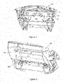
- FIG. 1 in a schematic side view the main components of a forage harvester 2 are shown.
- the forage harvester 2 is provided with a front attachment 4 which contains cutting equipment for cutting a crop.
- the cut crop is then fed through a series of compression rollers 6 in a compression roller housing 8 to a chopper drum assembly 10 where the crop is chopped into smaller pieces between a shear bar 30 and a plurality of chopper knives 36 mounted on a chopper drum 22.
- the chopped crop next passes through a first duct 12 and, in the illustrated embodiment, is fed through a cracker unit 14 where the crop is further crushed and threshed.
- the harvested crop is then blown upwards along a second duct 16 by an accelerator 18 and exits through a spout 20.
- the chopped crop may optionally pass directly from the chopper drum assembly 10 to the second duct 16.
- FIG. 2 shows a perspective view of a chopper drum assembly 10 incorporating the present invention.
- the chopper drum 22 is supported for rotation within a frame.
- the chopper drum 22 is driven about a central longitudinal axis by any suitable means.
- An upper end of the frame is provided with a housing 24 within which a sharpening apparatus may be located.
- the frame is provided with first and second parallel side walls 26,28.
- the chopper drum 22 is mounted in central portion of the frame supported between the side walls 26,28.
- the frame is further provided with further mounting means to enable the frame to be located in a suitable position within the forage harvester 2.
- a shear bar 30 is mounted to an upper part of a shear bar holder 32.
- the shear bar holder 32 is supported from the frame in a known manner so as to be pivoted about an axis 33 extending through a lower part of the shear bar holder 32. Pivoting of the shear bar holder about this axis enables a distance between the blades of the chopper knives 36 and an edge of the shear bar 30 to be adjusted and set.
- the wear plate assembly 40 comprises a support element 42 and at least one replaceable wear plate. In the illustrated embodiment, two such replaceable wear plates 80,90 are shown.
- the support element 42 comprises a generally planar portion 44 with a lip 46 towards a second end.
- the generally planar portion 44 is provided at a first end with an angled portion 44'.
- the lip 46 is provided at a number of locations with a locating surface 48. In the illustrated embodiment two such locating surfaces 48 are shown.
- the locating surfaces 48 are attached to the support element in any suitable manner, for example by welding.
- the generally planar portion 44 is provided in a first lateral region 44" with a plurality of first openings 50.
- Each first opening 50 is provided with a generally tubular element 52 secured to an outer surface of the generally planar portion 44.
- a first end of each generally tubular element 52 may be secured to the generally planar portion 44 within a first opening 50 in any suitable manner, for example by welding.
- a first end of each generally tubular element 52 may be secured to the generally planar portion 44 about a first opening 50, such that the first opening 50 and an inner part of each generally tubular element 52 are aligned.
- An outer end of each generally tubular element 52 is provided with an aperture 54 ( Figure 12 ).
- the first openings 50 and the associated tubular elements 52 may be of any suitable shape.
- first openings 50 are provided in the first lateral region 44": two in an upper central part and two in a lower part, each located towards an end of the first lateral region 44".
- Other numbers and distributions of the first openings 50 are possible.
- the generally planar portion 44 is provided in a second lateral region 44'" with a plurality of second openings 60.
- Each second opening 60 is provided with a generally tubular element 62 extending through the generally planar portion 44.
- Each generally tubular element 62 may be secured within a second opening 60 to the generally planar portion 44 in any suitable manner, for example by welding.
- An outer end of each generally tubular element 62 is provided with an aperture 64 ( Figure 13 ).
- the first openings 60 and the associated tubular elements 62 may be of any suitable shape.
- second openings 60 are provided in the second lateral region 44"': two in a lower central part having a first lateral spacing and two in an upper part, having a second lateral spacing greater than the first.
- Other numbers and arrangements of the second openings are possible.
- the wear plate assembly 40 further comprises a first element 70 extending laterally across the angled portion 44' of the generally planar portion 44 of the support element 42.
- the first element 70 is fixedly secured in position in relation to the support element 42 by any suitable method, for example by welding.
- the first element 70 may be of any suitable shape. In the illustrated embodiment, the first element is generally planar.
- the first element 70 is provided with a number of openings or windows 72. In the illustrated embodiment, two such windows 72 are provided.
- the windows 72 are used to secure and locate a pair of block elements 74.
- the block elements 74 may be secured in any suitable manner, for example by welding.
- Each of the block elements 74 is provided with a central through bore 76.
- the block elements 74 extend into suitably shaped openings in the shear bar holder 32.
- a pin or shaft 78 extends though the shear bar holder and the bores 74 to provide an axis of rotation for the support 42 with respect to the shear bar holder 32.
- a first removable wear plate 80 is releasably mounted on the generally planar portion 44 of the support element 42 next to the first element 70. It can be seen that, in the illustrated embodiment, the first removable wear plate 80 overlies the angled portion 44' adjacent the first element 70 and the first lateral region 44" of the generally planar portion 44 of the support 42.
- the first removable wear plate 80 is of arcuate form such that an inner surface of the first removable wear plate 80 follows the desired dimensions of the chopper drum assembly 10. In use, the inner surface of the first removable wear plate 80 sits flush with an inner surface of the adjacent first element 70.
- An outer surface of the first removable wear plate 80 is provided with a number of laterally spaced bosses 82, each boss being provided with a threaded inner bore 84.
- An outer surface 86 of each boss 82 may be of any suitable shape. Each boss is permanently secured to the outer surface of the first removable wear plate 80 in any suitable manner, for example by welding.
- a second removable wear plate 90 is releasably mounted on the generally planar portion 44 of the support element 42 next to the first removable wear plate 80.
- the second removable wear plate 90 is of arcuate form such that the inner surface of the second removable wear plate 90 follows the desired dimensions of the chopper drum assembly 10. In use, the inner surface of the second removable wear plate 90 sits flush with the inner surface of the adjacent first removable wear plate 80.
- An outer surface of the second removable wear plate 60 is provided with a number of laterally spaced bosses 92, each boss 92 being provided with a threaded inner bore 94.
- An outer surface 96 of each boss 92 may be of any suitable shape.
- Each boss 92 is permanently secured to the outer surface of the second removable wear plate 90 in any suitable manner, for example by welding.
- bosses 82 on the outer side of the first removable plate 80 are adapted to be seated within a corresponding first opening 50 or an inner part of the tubular member 52 and that the bosses 92 on the outer side of the first removable plate 90 are adapted to be seated within a corresponding inner part of the tubular member 62.
- each may be of any suitable shape, the shapes are required to match.
- first threaded fasteners 58 are used to secure the first removable plate 80 in position and a plurality of second threaded fasteners 68 are used to secure the second moveable plate 90 in position ( Figures 10 to 13 ).
- FIG. 5A , 10 and 11 An example fixing of the first removable wear plate 80 is illustrated in Figures 5, 5A , 10 and 11 where the first removable wear plate 80 is shown overlying the first planar region of the planar portion 44 of the support element 42.
- the outer surface of the boss 86 is located within an upper region of the generally tubular element 52.
- a threaded fastener 58 extends through a washer assembly 56 and the aperture 54 in the end of the generally tubular element 52 and engages with the threaded inner bore 84 of the boss 82 to draw the boss 82 into the generally tubular element 52 thereby securing the first removable plate 80 in position against the first planar region of the planar portion 44 of the support element 42.
- Any suitable washer assembly 56 may be used.
- FIG. 5A , 10 and 11 An example fixing of the second removable wear plate 90 is illustrated in Figures 5, 5A , 10 and 11 where the second removable wear plate 90 is shown overlying the second planar region of the planar portion 44 of the support element 42.
- the outer surface of the boss 92 is located within an upper region of the generally tubular element 62.
- a threaded fastener 68 extends through a washer assembly 66 and the aperture 64 in the end of the generally tubular element 62 and engages with the threaded inner bore 94 of the boss 92 to draw the boss 92 into the generally tubular element 62 thereby securing the second removable plate 80 in position against the second planar region of the planar portion 44 of the support element 42.
- Any suitable washer assembly 66 may be used.
- the shear bar holder 32 is mounted to the frame and is rotatable with respect to the frame about the axis 33 extending through a lower part of the shear bar holder 32. This allows the upper end of the wear plate assembly to be located in a desired position.
- a wedge adjuster 100 can be located between an element 110 of the frame and the support surface 38 to locate a lower end of the wear plate assembly 40 with respect to the frame and the chopper drum 22. It will be appreciated that this adjustment can be conducted without affecting the location of the shear bar 30 (or the upper end of the wear plate assembly 40).
- the threaded fastener 58,68 enters through the support element 42.
- the threaded fastener 56,58 is received within a blind bore former by the boss 82,92 and the outer surface of the associated wear plate 80,90. As such the threaded fastener 58,68 cannot be exposed to the processed crop.
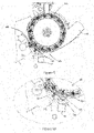
- the wear plate assembly By releasing the wedge adjuster 100 and removing the wedge, the wear plate assembly is able to rotate about the shaft 78. In this way the lower end of the wear plate assembly 40 is lowered away from the chopper drum 10 to the position shown in Figures 12 and 13 .
- an operator In order to remove a wear plate, an operator first loosens the associated threaded fasteners 58,68 such that the free ends of the threaded fasteners 58,68 no longer engage with the relevant threaded inner bore 84,94.
- the wedge of the wedge adjuster 100 is removed allowing the lower end of the wear plate assembly 40 to be lowered.
- the wear plates 80,90 can then be removed (as shown by the arrows in Figures 12 and 13 ). From Figures 12 and 13 it will be understood that it is easier to first remove the second removable plate 90 before removing the first removable plate 80. It will be understood that accessing the removeable wear plates 80,90 in this way the operator does not need to obtain access to the interior of the chopper drum assembly.
- the wedge of the wedge adjuster 100 is replaced and the wedge adjuster 100 adjusted such that the wear plate assembly 40 is in the desired position in relation to the chopper drum 22.
- the operator then tightens the screws 58,68 as required. Any final adjustments to the wedge adjuster 100 can then be made.
Abstract
Description
- The present invention relates to an agricultural harvester, in particular a self-propelled forage harvester for use in cutting an agricultural crop, for example cutting corn and grass for stock feed and further in relation to a replaceable wear plate for such a harvester.
- During operation of a forage harvester agricultural crop is fed into the forage harvester and comminuted or rendered into smaller particles on its passage through the forage harvester before being discharged. The comminuted crop causes particular wear on some of the surfaces that it impacts upon when travelling through the harvester. For example, this can be a particular problem in relation to the surfaces in a chopper drum housing or a blower housing.
- To address this problem replaceable wear plates have been developed to provide improved longevity to these regions of the forage harvester. In known systems, the wear plate may be held in place by screwing of the wear plate to a suitable support. It will be understood that removing the screws to allow the wear plate to be removed and replaced can be awkward, tedious and time consuming for the operator. In particular this may require some disassembly of the associated housing to permit access to the screws.
- Additionally, the screws may become loose due to vibration during operation of the forage harvester and may subsequently be drawn into the processed crop and then into the resulting animal feed, causing a risk of harm to any animals consuming the feed. Alternatively, or additionally, during transit through the forage harvester the screws may interfere with other elements of the forage harvester as they pass through the forage harvester causing damage to such other elements.
- Further should all of the screws become loose there is a danger that the wear plate itself may become dislodged and drawn into the flow of crop through the forage harvester. At best the dislodged wear plate may cause a blockage, but potentially the dislodged wear plate could interfere with other elements of the forage harvester as it passes through the forage harvester causing damage to such other elements.
- It is an advantage of the present invention that it provides an improved wear plate assembly for use in an agricultural harvester such as a forage harvester.
- According to a first aspect of the present invention, a wear plate assembly for an agricultural harvester comprises a support element having a number of lateral regions, the or each lateral region being provided with a plurality of first engagement features, one or more replaceable wear plates provided on a first side with a plurality of second engagement features for engagement with the first engagement features, and a plurality of fastenings to secure the or each replaceable wear plate to the support element through the engagement features.
- Preferably, each of the first engagement features comprises a female fitting and each of the second engagement features comprises a male fitting for engagement with a respective female fitting.
- Preferably, each of the first engagement features comprises a tubular member having an internal section and each of the second engagement features comprises a tubular member having an external section sized for seating within the internal section of the first engagement feature.
- Preferably each of the first engagement features is provided with an end portion having a threaded opening, each of the second engagement features is provided with an internal threaded opening and wherein each of the plurality of fastenings is a threaded fastening adapted to engage with each of the threaded opening and the internal threaded opening to secure the or each replaceable wear plate to the support.
- Preferably the one or more replaceable wear plates comprises first and second replaceable wear plates.
- According to a second aspect of the invention, an agricultural harvester comprises a wear plate assembly according to the first aspect of the present invention.
- Preferably, the agricultural harvester further comprises a shear bar assembly to which the support element of the wear plate assembly is mounted.
- According to a third aspect of the present invention a method of assembly of a wear plate assembly according to the first aspect of the invention comprises the steps of locating a first replaceable wear plate such that the second engagement features are seated within the first engagement features, introducing each of the plurality of fastening members through an associated first engagement feature of the support element and into an associated second engagement feature to secure the first replaceable wear plate to the support element through the first and second engagement features.
- Preferably where the wear plate assembly includes a second replaceable wear plate the method further comprises locating the second replaceable wear plate such that the first engagement features are seated within the second engagement features, introducing each of the plurality of fastening members through an associated first engagement feature of the support element and into an associated second engagement feature to secure the second replaceable wear plate to the support element through the first and second engagement features.
- The invention will now be described, by way of example only, with reference to the accompanying drawings, in which:
-
Figure 1 shows a schematic side view of a forage harvester for use with the present invention; -
Figure 2 shows a perspective view of a chopper drum assembly suitable for use with the present invention; -
Figure 3 shows a view from below of the chopper drum assembly ofFigure 2 showing a portion of a wear plate assembly in accordance with the present invention; -
Figure 4 shows a perspective view of a lower portion of the chopper drum assembly from which the chopper drum has been omitted to show a portion of a wear plate assembly in accordance with the present invention; -
Figure 5 shows a side section of the chopper drum assembly together with other elements of a forage harvester; -
Figure 5A shows a detail of a lower portion ofFigure 5 ; -
Figure 6 shows a perspective view from below of a support element forming a part of a wear plate assembly in accordance with the present invention; -
Figure 7 shows a perspective view from above of the support element ofFigure 6 ; -
Figure 8 shows view similar to that ofFigure 7 illustrating a first replaceable wear plate attached to the support element; -
Figure 9 shows the support element fitted with both a first and a second replaceable wear plate; -
Figure 10 shows a detail of a first section of a wear plate assembly according to the invention mounted in a chopper drum assembly; -
Figure 11 shows a detail of a second section of a wear plate assembly displaced laterally from the first section ofFigure 10 ; -
Figure 12 shows a side section showing removal of the second replaceable wear plate of the wear plate assembly; and -
Figure 13 shows a side section showing removal of the first replaceable wear plate of the wear plate assembly. - The invention will now be described in the following detailed description with reference to the drawings, wherein preferred embodiments are described in detail to enable practice of the invention. Although the invention is described with reference to these specific preferred embodiments, it will be understood that the invention is not limited to these preferred embodiments. But to the contrary, the invention includes numerous alternatives, modifications and equivalents as will become apparent from consideration of the following detailed description.
- Reference to terms such as longitudinal, transverse and vertical are made with respect to a longitudinal vehicle axis which is parallel to a normal forward direction of travel.
- With reference to
Figure 1 , in a schematic side view the main components of a forage harvester 2 are shown. The forage harvester 2 is provided with afront attachment 4 which contains cutting equipment for cutting a crop. The cut crop is then fed through a series of compression rollers 6 in a compression roller housing 8 to achopper drum assembly 10 where the crop is chopped into smaller pieces between ashear bar 30 and a plurality ofchopper knives 36 mounted on achopper drum 22. The chopped crop next passes through afirst duct 12 and, in the illustrated embodiment, is fed through a cracker unit 14 where the crop is further crushed and threshed. The harvested crop is then blown upwards along a second duct 16 by an accelerator 18 and exits through aspout 20. In an alternative embodiment, the chopped crop may optionally pass directly from thechopper drum assembly 10 to the second duct 16. - In describing the present invention the term 'inner' is used to describe those elements of the invention which are, in use, closer to an axis of rotation of the chopper drum and 'outer' the opposite. Similarly references to 'upper' and 'lower' are to be understood with reference to the forage harvester in position on level ground.
-
Figure 2 shows a perspective view of achopper drum assembly 10 incorporating the present invention. Thechopper drum 22 is supported for rotation within a frame. Thechopper drum 22 is driven about a central longitudinal axis by any suitable means. An upper end of the frame is provided with ahousing 24 within which a sharpening apparatus may be located. The frame is provided with first and secondparallel side walls - The
chopper drum 22 is mounted in central portion of the frame supported between theside walls - A
shear bar 30 is mounted to an upper part of ashear bar holder 32. Theshear bar holder 32 is supported from the frame in a known manner so as to be pivoted about anaxis 33 extending through a lower part of theshear bar holder 32. Pivoting of the shear bar holder about this axis enables a distance between the blades of thechopper knives 36 and an edge of theshear bar 30 to be adjusted and set. - Elements of a
wear plate assembly 40 in accordance with the present invention may best be seen inFigures 6 to 9 . Thewear plate assembly 40 comprises asupport element 42 and at least one replaceable wear plate. In the illustrated embodiment, two suchreplaceable wear plates - The
support element 42 comprises a generallyplanar portion 44 with alip 46 towards a second end. The generallyplanar portion 44 is provided at a first end with an angled portion 44'. Thelip 46 is provided at a number of locations with a locatingsurface 48. In the illustrated embodiment two such locating surfaces 48 are shown. The locating surfaces 48 are attached to the support element in any suitable manner, for example by welding. - The generally
planar portion 44 is provided in a firstlateral region 44" with a plurality of first openings 50. Each first opening 50 is provided with a generallytubular element 52 secured to an outer surface of the generallyplanar portion 44. A first end of each generallytubular element 52 may be secured to the generallyplanar portion 44 within a first opening 50 in any suitable manner, for example by welding. Alternatively, a first end of each generallytubular element 52 may be secured to the generallyplanar portion 44 about a first opening 50, such that the first opening 50 and an inner part of each generallytubular element 52 are aligned. An outer end of each generallytubular element 52 is provided with an aperture 54 (Figure 12 ). The first openings 50 and the associatedtubular elements 52 may be of any suitable shape. - In the illustrated embodiment four such first openings 50 (and the associated tubular elements 52) are provided in the first
lateral region 44": two in an upper central part and two in a lower part, each located towards an end of the firstlateral region 44". Other numbers and distributions of the first openings 50 are possible. - The generally
planar portion 44 is provided in a second lateral region 44'" with a plurality ofsecond openings 60. Eachsecond opening 60 is provided with a generallytubular element 62 extending through the generallyplanar portion 44. Each generallytubular element 62 may be secured within asecond opening 60 to the generallyplanar portion 44 in any suitable manner, for example by welding. An outer end of each generallytubular element 62 is provided with an aperture 64 (Figure 13 ). Thefirst openings 60 and the associatedtubular elements 62 may be of any suitable shape. - In the illustrated embodiment four such second openings 60 (and the associated tubular elements 62) are provided in the second
lateral region 44"': two in a lower central part having a first lateral spacing and two in an upper part, having a second lateral spacing greater than the first. Other numbers and arrangements of the second openings are possible. - The
wear plate assembly 40 further comprises afirst element 70 extending laterally across the angled portion 44' of the generallyplanar portion 44 of thesupport element 42. Thefirst element 70 is fixedly secured in position in relation to thesupport element 42 by any suitable method, for example by welding. Thefirst element 70 may be of any suitable shape. In the illustrated embodiment, the first element is generally planar. Thefirst element 70 is provided with a number of openings orwindows 72. In the illustrated embodiment, twosuch windows 72 are provided. Thewindows 72 are used to secure and locate a pair ofblock elements 74. Theblock elements 74 may be secured in any suitable manner, for example by welding. Each of theblock elements 74 is provided with a central throughbore 76. In use theblock elements 74 extend into suitably shaped openings in theshear bar holder 32. A pin or shaft 78 (Figure 5A ) extends though the shear bar holder and thebores 74 to provide an axis of rotation for thesupport 42 with respect to theshear bar holder 32. - A first
removable wear plate 80 is releasably mounted on the generallyplanar portion 44 of thesupport element 42 next to thefirst element 70. It can be seen that, in the illustrated embodiment, the firstremovable wear plate 80 overlies the angled portion 44' adjacent thefirst element 70 and the firstlateral region 44" of the generallyplanar portion 44 of thesupport 42. The firstremovable wear plate 80 is of arcuate form such that an inner surface of the firstremovable wear plate 80 follows the desired dimensions of thechopper drum assembly 10. In use, the inner surface of the firstremovable wear plate 80 sits flush with an inner surface of the adjacentfirst element 70. An outer surface of the firstremovable wear plate 80 is provided with a number of laterally spacedbosses 82, each boss being provided with a threadedinner bore 84. An outer surface 86 of eachboss 82 may be of any suitable shape. Each boss is permanently secured to the outer surface of the firstremovable wear plate 80 in any suitable manner, for example by welding. - A second
removable wear plate 90 is releasably mounted on the generallyplanar portion 44 of thesupport element 42 next to the firstremovable wear plate 80. The secondremovable wear plate 90 is of arcuate form such that the inner surface of the secondremovable wear plate 90 follows the desired dimensions of thechopper drum assembly 10. In use, the inner surface of the secondremovable wear plate 90 sits flush with the inner surface of the adjacent firstremovable wear plate 80. An outer surface of the secondremovable wear plate 60 is provided with a number of laterally spacedbosses 92, eachboss 92 being provided with a threadedinner bore 94. An outer surface 96 of eachboss 92 may be of any suitable shape. Eachboss 92 is permanently secured to the outer surface of the secondremovable wear plate 90 in any suitable manner, for example by welding. - It will be appreciated that the
bosses 82 on the outer side of the firstremovable plate 80 are adapted to be seated within a corresponding first opening 50 or an inner part of thetubular member 52 and that thebosses 92 on the outer side of the firstremovable plate 90 are adapted to be seated within a corresponding inner part of thetubular member 62. Thus while each may be of any suitable shape, the shapes are required to match. - In use a plurality of first threaded
fasteners 58 are used to secure the firstremovable plate 80 in position and a plurality of second threadedfasteners 68 are used to secure the secondmoveable plate 90 in position (Figures 10 to 13 ). - An example fixing of the first
removable wear plate 80 is illustrated inFigures 5, 5A ,10 and 11 where the firstremovable wear plate 80 is shown overlying the first planar region of theplanar portion 44 of thesupport element 42. The outer surface of the boss 86 is located within an upper region of the generallytubular element 52. A threadedfastener 58 extends through awasher assembly 56 and theaperture 54 in the end of the generallytubular element 52 and engages with the threadedinner bore 84 of theboss 82 to draw theboss 82 into the generallytubular element 52 thereby securing the firstremovable plate 80 in position against the first planar region of theplanar portion 44 of thesupport element 42. Anysuitable washer assembly 56 may be used. - An example fixing of the second
removable wear plate 90 is illustrated inFigures 5, 5A ,10 and 11 where the secondremovable wear plate 90 is shown overlying the second planar region of theplanar portion 44 of thesupport element 42. The outer surface of theboss 92 is located within an upper region of the generallytubular element 62. A threadedfastener 68 extends through awasher assembly 66 and theaperture 64 in the end of the generallytubular element 62 and engages with the threadedinner bore 94 of theboss 92 to draw theboss 92 into the generallytubular element 62 thereby securing the secondremovable plate 80 in position against the second planar region of theplanar portion 44 of thesupport element 42. Anysuitable washer assembly 66 may be used. - As noted, the
shear bar holder 32 is mounted to the frame and is rotatable with respect to the frame about theaxis 33 extending through a lower part of theshear bar holder 32. This allows the upper end of the wear plate assembly to be located in a desired position. Awedge adjuster 100 can be located between anelement 110 of the frame and the support surface 38 to locate a lower end of thewear plate assembly 40 with respect to the frame and thechopper drum 22. It will be appreciated that this adjustment can be conducted without affecting the location of the shear bar 30 (or the upper end of the wear plate assembly 40). - It can be seen in each case that the threaded
fastener support element 42. In each case the threadedfastener boss wear plate fastener - By releasing the
wedge adjuster 100 and removing the wedge, the wear plate assembly is able to rotate about theshaft 78. In this way the lower end of thewear plate assembly 40 is lowered away from thechopper drum 10 to the position shown inFigures 12 and 13 . - In order to remove a wear plate, an operator first loosens the associated threaded
fasteners fasteners inner bore wedge adjuster 100 is removed allowing the lower end of thewear plate assembly 40 to be lowered. Thewear plates Figures 12 and 13 ). FromFigures 12 and 13 it will be understood that it is easier to first remove the secondremovable plate 90 before removing the firstremovable plate 80. It will be understood that accessing the removeable wearplates - Similarly, when replacing the
replaceable wear plates replaceable wear plate 80 once the secondreplaceable wear plate 90 has been removed. - Once the desired replaceable wear plate or plates have been replaced, the wedge of the
wedge adjuster 100 is replaced and thewedge adjuster 100 adjusted such that thewear plate assembly 40 is in the desired position in relation to thechopper drum 22. The operator then tightens thescrews wedge adjuster 100 can then be made. - It will be understood that should the
screws chopper drum assembly 10 without a risk that they will fall into the flow of processed crop passing through the forage harvester 2. - Further, the matching shapes of the
bosses tubular elements replaceable wear plates - From reading the present disclosure, other modifications will be apparent to persons skilled in the art. Such modifications may involve other features which are already known in the field of self-propelled forage harvesters and component parts therefore and which may be used instead of or in addition to features already described herein.
Claims (9)
- A wear plate assembly for an agricultural harvester comprises a support element having a number of lateral regions, the or each lateral region being provided with a plurality of first engagement features, one or more replaceable wear plates provided on a first side with a plurality of second engagement features for engagement with the first engagement features, and a plurality of fastenings to secure the or each replaceable wear plate to the support element through the engagement features.
- A wear plate assembly according to claim 1, characterised in that each of the first engagement features comprises a female fitting and each of the second engagement features comprises a male fitting for engagement with a respective female fitting.
- A wear plate assembly according to claim 1 or claim 2, characterised in that each of the first engagement features comprises a tubular member having an internal section and each of the second engagement features comprises a tubular member having an external section sized for seating within the internal section of a respective first engagement feature.
- A wear plate assembly according to any of claim 1 to claim 3, characterised in that each of the first engagement features is provided with an end portion having a threaded opening, each of the second engagement features is provided with an internal threaded opening and in that each of the plurality of fastenings is a threaded fastening adapted to engage with each of the threaded opening and the internal threaded opening to secure the or each replaceable wear plate to the support.
- A wear plate assembly according to any of claim 1 to claim 4, characterised in that the one or more replaceable wear plates comprises first and second replaceable wear plates.
- An agricultural harvester comprising a wear plate assembly according to any of claim 1 to claim 5.
- An agricultural harvester according to claim 6, characterised in that the agricultural harvester further comprises a shear bar assembly to which the support element of the wear plate assembly is mounted.
- A method of assembly of a wear plate assembly comprising a support element having a number of lateral regions, the or each lateral region being provided with a plurality of first engagement features, one or more replaceable wear plates provided on one side with a plurality of second engagement features for engagement with the first engagement features, and a plurality of fastenings to secure the or each replaceable wear plate to the support through the engagement features comprises the steps of locating a first replaceable wear plate such that the second engagement features are seated within the first engagement features, introducing each of the plurality of fastening members through an associated first engagement feature of the support element and into an associated second engagement feature to secure the first replaceable wear plate to the support element through the first and second engagement features.
- A method according to claim 8, characterised in that where the wear plate assembly includes a second replaceable wear plate the method further comprises the steps of locating the second replaceable wear plate such that the first engagement features are seated within the second engagement features, introducing each of the plurality of fastening members through an associated first engagement feature of the support element and into an associated second engagement feature to secure the second replaceable wear plate to the support element through the first and second engagement features.
Applications Claiming Priority (1)
| Application Number | Priority Date | Filing Date | Title |
|---|---|---|---|
| GBGB2020459.0A GB202020459D0 (en) | 2020-12-23 | 2020-12-23 | Forage harvester |
Publications (1)
| Publication Number | Publication Date |
|---|---|
| EP4018811A1 true EP4018811A1 (en) | 2022-06-29 |
Family
ID=74221039
Family Applications (1)
| Application Number | Title | Priority Date | Filing Date |
|---|---|---|---|
| EP21207441.3A Pending EP4018811A1 (en) | 2020-12-23 | 2021-11-10 | Forage harvester |
Country Status (3)
| Country | Link |
|---|---|
| US (1) | US20220192096A1 (en) |
| EP (1) | EP4018811A1 (en) |
| GB (1) | GB202020459D0 (en) |
Cited By (1)
| Publication number | Priority date | Publication date | Assignee | Title |
|---|---|---|---|---|
| US11980127B2 (en) * | 2020-12-23 | 2024-05-14 | Agco International Gmbh | Forage harvester |
Families Citing this family (2)
| Publication number | Priority date | Publication date | Assignee | Title |
|---|---|---|---|---|
| US20220279713A1 (en) * | 2021-03-03 | 2022-09-08 | Fecon, Llc | Apparatus for land clearing and preparation having chamber inserts |
| US20220279712A1 (en) * | 2021-03-03 | 2022-09-08 | Fecon, Llc | Apparatus for land clearing and preparation having interchangeable chamber inserts |
Citations (3)
| Publication number | Priority date | Publication date | Assignee | Title |
|---|---|---|---|---|
| US4383652A (en) * | 1981-04-20 | 1983-05-17 | Sperry Corporation | Shredbar apparatus |
| CA2328744C (en) * | 2000-03-14 | 2003-09-16 | Deere & Company | Rotary mower cutter disc having self-cleaning knife mount shield |
| US20160333547A1 (en) * | 2015-05-13 | 2016-11-17 | Winter Equipment Company | Reinforced elastomeric blade |
-
2020
- 2020-12-23 GB GBGB2020459.0A patent/GB202020459D0/en not_active Ceased
-
2021
- 2021-11-10 EP EP21207441.3A patent/EP4018811A1/en active Pending
- 2021-12-23 US US17/645,795 patent/US20220192096A1/en active Pending
Patent Citations (3)
| Publication number | Priority date | Publication date | Assignee | Title |
|---|---|---|---|---|
| US4383652A (en) * | 1981-04-20 | 1983-05-17 | Sperry Corporation | Shredbar apparatus |
| CA2328744C (en) * | 2000-03-14 | 2003-09-16 | Deere & Company | Rotary mower cutter disc having self-cleaning knife mount shield |
| US20160333547A1 (en) * | 2015-05-13 | 2016-11-17 | Winter Equipment Company | Reinforced elastomeric blade |
Cited By (1)
| Publication number | Priority date | Publication date | Assignee | Title |
|---|---|---|---|---|
| US11980127B2 (en) * | 2020-12-23 | 2024-05-14 | Agco International Gmbh | Forage harvester |
Also Published As
| Publication number | Publication date |
|---|---|
| GB202020459D0 (en) | 2021-02-03 |
| US20220192096A1 (en) | 2022-06-23 |
Similar Documents
| Publication | Publication Date | Title |
|---|---|---|
| EP4018811A1 (en) | Forage harvester | |
| EP1074175B1 (en) | Distributor for the residues of crops ejected from a combine | |
| US6192666B1 (en) | Lawn mower | |
| EP0793412B1 (en) | Device for chopping the stalks after the ears of corn have been cut off in a combine harvester | |
| US10582665B1 (en) | Helical auger flight assemblies and thresher formed therewith | |
| CN106612892B (en) | Single fastener attachment device for a shredding knife | |
| US4505434A (en) | Forage harvester recutter screen | |
| EP1570725A1 (en) | Forage harvester blower | |
| US7771261B2 (en) | Knife blade for a chopper of a combine harvester | |
| EP0803181B1 (en) | Crop processor apparatus for forage harvester | |
| US5919087A (en) | Concave latch mechanism for an agricultural combine | |
| US10058027B2 (en) | Agricultural harvester row unit | |
| US9089094B1 (en) | Combine thresher with helical auger flights having sacrificial shield and wear plates | |
| CN108934413B (en) | A chopper subassembly and combine for combine | |
| US6131837A (en) | Segmented crop processor roll for forage harvester | |
| US5024051A (en) | Bolted double sickle cutterbar | |
| EP0244892A2 (en) | Paddle wheel assembly for forage harvesters | |
| US7497775B1 (en) | Rear accessible sieve retainer | |
| EP1849348B1 (en) | Fine crushing device with removable crusher blades | |
| DE19753486B4 (en) | chopping | |
| US6261176B1 (en) | Enclosed threshing cylinder with rasp-type bars | |
| US3525375A (en) | Forage harvester recutter screen | |
| US10085383B1 (en) | Helical auger flight assemblies and thresher formed therewith | |
| US3963183A (en) | Resharpenable recutter screen for forage harvester | |
| GB2027334A (en) | Grass forage harvester |
Legal Events
| Date | Code | Title | Description |
|---|---|---|---|
| PUAI | Public reference made under article 153(3) epc to a published international application that has entered the european phase |
Free format text: ORIGINAL CODE: 0009012 |
|
| STAA | Information on the status of an ep patent application or granted ep patent |
Free format text: STATUS: THE APPLICATION HAS BEEN PUBLISHED |
|
| AK | Designated contracting states |
Kind code of ref document: A1 Designated state(s): AL AT BE BG CH CY CZ DE DK EE ES FI FR GB GR HR HU IE IS IT LI LT LU LV MC MK MT NL NO PL PT RO RS SE SI SK SM TR |
|
| STAA | Information on the status of an ep patent application or granted ep patent |
Free format text: STATUS: REQUEST FOR EXAMINATION WAS MADE |
|
| 17P | Request for examination filed |
Effective date: 20230102 |
|
| RBV | Designated contracting states (corrected) |
Designated state(s): AL AT BE BG CH CY CZ DE DK EE ES FI FR GB GR HR HU IE IS IT LI LT LU LV MC MK MT NL NO PL PT RO RS SE SI SK SM TR |
|
| P01 | Opt-out of the competence of the unified patent court (upc) registered |
Effective date: 20230518 |
|
| STAA | Information on the status of an ep patent application or granted ep patent |
Free format text: STATUS: EXAMINATION IS IN PROGRESS |