EP4017793B1 - Hydrofoil system and marine vessel - Google Patents
Hydrofoil system and marine vessel Download PDFInfo
- Publication number
- EP4017793B1 EP4017793B1 EP19756173.1A EP19756173A EP4017793B1 EP 4017793 B1 EP4017793 B1 EP 4017793B1 EP 19756173 A EP19756173 A EP 19756173A EP 4017793 B1 EP4017793 B1 EP 4017793B1
- Authority
- EP
- European Patent Office
- Prior art keywords
- hydrofoil
- marine vessel
- hull
- hydrofoils
- stowed position
- Prior art date
- Legal status (The legal status is an assumption and is not a legal conclusion. Google has not performed a legal analysis and makes no representation as to the accuracy of the status listed.)
- Active
Links
Images



Classifications
-
- B—PERFORMING OPERATIONS; TRANSPORTING
- B63—SHIPS OR OTHER WATERBORNE VESSELS; RELATED EQUIPMENT
- B63B—SHIPS OR OTHER WATERBORNE VESSELS; EQUIPMENT FOR SHIPPING
- B63B1/00—Hydrodynamic or hydrostatic features of hulls or of hydrofoils
- B63B1/16—Hydrodynamic or hydrostatic features of hulls or of hydrofoils deriving additional lift from hydrodynamic forces
- B63B1/24—Hydrodynamic or hydrostatic features of hulls or of hydrofoils deriving additional lift from hydrodynamic forces of hydrofoil type
- B63B1/28—Hydrodynamic or hydrostatic features of hulls or of hydrofoils deriving additional lift from hydrodynamic forces of hydrofoil type with movable hydrofoils
- B63B1/30—Hydrodynamic or hydrostatic features of hulls or of hydrofoils deriving additional lift from hydrodynamic forces of hydrofoil type with movable hydrofoils retracting or folding
-
- B—PERFORMING OPERATIONS; TRANSPORTING
- B63—SHIPS OR OTHER WATERBORNE VESSELS; RELATED EQUIPMENT
- B63B—SHIPS OR OTHER WATERBORNE VESSELS; EQUIPMENT FOR SHIPPING
- B63B1/00—Hydrodynamic or hydrostatic features of hulls or of hydrofoils
- B63B1/16—Hydrodynamic or hydrostatic features of hulls or of hydrofoils deriving additional lift from hydrodynamic forces
- B63B1/24—Hydrodynamic or hydrostatic features of hulls or of hydrofoils deriving additional lift from hydrodynamic forces of hydrofoil type
- B63B1/26—Hydrodynamic or hydrostatic features of hulls or of hydrofoils deriving additional lift from hydrodynamic forces of hydrofoil type having more than one hydrofoil
-
- B—PERFORMING OPERATIONS; TRANSPORTING
- B63—SHIPS OR OTHER WATERBORNE VESSELS; RELATED EQUIPMENT
- B63B—SHIPS OR OTHER WATERBORNE VESSELS; EQUIPMENT FOR SHIPPING
- B63B1/00—Hydrodynamic or hydrostatic features of hulls or of hydrofoils
- B63B1/16—Hydrodynamic or hydrostatic features of hulls or of hydrofoils deriving additional lift from hydrodynamic forces
- B63B1/24—Hydrodynamic or hydrostatic features of hulls or of hydrofoils deriving additional lift from hydrodynamic forces of hydrofoil type
- B63B1/28—Hydrodynamic or hydrostatic features of hulls or of hydrofoils deriving additional lift from hydrodynamic forces of hydrofoil type with movable hydrofoils
- B63B1/285—Hydrodynamic or hydrostatic features of hulls or of hydrofoils deriving additional lift from hydrodynamic forces of hydrofoil type with movable hydrofoils changing the angle of attack or the lift of the foil
-
- B—PERFORMING OPERATIONS; TRANSPORTING
- B63—SHIPS OR OTHER WATERBORNE VESSELS; RELATED EQUIPMENT
- B63H—MARINE PROPULSION OR STEERING
- B63H20/00—Outboard propulsion units, e.g. outboard motors or Z-drives; Arrangements thereof on vessels
- B63H20/08—Means enabling movement of the position of the propulsion element, e.g. for trim, tilt or steering; Control of trim or tilt
- B63H20/10—Means enabling trim or tilt, or lifting of the propulsion element when an obstruction is hit; Control of trim or tilt
- B63H20/106—Means enabling lifting of the propulsion element in a substantially vertical, linearly sliding movement
-
- B—PERFORMING OPERATIONS; TRANSPORTING
- B63—SHIPS OR OTHER WATERBORNE VESSELS; RELATED EQUIPMENT
- B63B—SHIPS OR OTHER WATERBORNE VESSELS; EQUIPMENT FOR SHIPPING
- B63B1/00—Hydrodynamic or hydrostatic features of hulls or of hydrofoils
- B63B1/16—Hydrodynamic or hydrostatic features of hulls or of hydrofoils deriving additional lift from hydrodynamic forces
- B63B1/18—Hydrodynamic or hydrostatic features of hulls or of hydrofoils deriving additional lift from hydrodynamic forces of hydroplane type
- B63B1/20—Hydrodynamic or hydrostatic features of hulls or of hydrofoils deriving additional lift from hydrodynamic forces of hydroplane type having more than one planing surface
- B63B2001/202—Hydrodynamic or hydrostatic features of hulls or of hydrofoils deriving additional lift from hydrodynamic forces of hydroplane type having more than one planing surface divided by transverse steps
-
- B—PERFORMING OPERATIONS; TRANSPORTING
- B63—SHIPS OR OTHER WATERBORNE VESSELS; RELATED EQUIPMENT
- B63B—SHIPS OR OTHER WATERBORNE VESSELS; EQUIPMENT FOR SHIPPING
- B63B1/00—Hydrodynamic or hydrostatic features of hulls or of hydrofoils
- B63B1/16—Hydrodynamic or hydrostatic features of hulls or of hydrofoils deriving additional lift from hydrodynamic forces
- B63B1/24—Hydrodynamic or hydrostatic features of hulls or of hydrofoils deriving additional lift from hydrodynamic forces of hydrofoil type
- B63B1/28—Hydrodynamic or hydrostatic features of hulls or of hydrofoils deriving additional lift from hydrodynamic forces of hydrofoil type with movable hydrofoils
- B63B2001/281—Hydrodynamic or hydrostatic features of hulls or of hydrofoils deriving additional lift from hydrodynamic forces of hydrofoil type with movable hydrofoils movable about an axis substantially parallel to the flow direction
Definitions
- the present invention relates to a foldable hydrofoil system and a marine vessel with such a system.
- hydrofoil boats are usually provided with at least one hydrofoil consisting of a wing like structure mounted on struts below the hull, or across the keels of a catamaran in a variety of boats.
- a hydrofoil operates in the same way as a wing-shaped airfoil to create a lifting force and can have a similar cross-section.
- the hydrofoil elements below the hull develop enough lift to raise the hull out of the water, which greatly reduces hull drag. This provides a corresponding increase in speed and fuel efficiency, as less propulsive force is required to drive the vessel.
- the upward force exerted by the hydrofoil lifts the body of the vessel clear of the water, thereby decreasing drag of the hull and increasing the speed of the vessel.
- the lifting force eventually balances with the weight of the craft, reaching a point where the hydrofoil no longer lifts out of the water but remains in equilibrium. Since wave resistance and other impeding forces such as various types of drag on the hull are eliminated as the hull lifts clear, turbulence and drag act increasingly on the much smaller surface area of the hydrofoil, and decreasingly on the relative larger area of the hull, creating a marked increase in speed. In the case of fixed hydrofoils, the lifting force will be dependent on the speed of the vessel.
- hydrofoils can be provided with control surfaces in the same way as an aircraft wing, whereby the control surfaces can be angled to increase or decrease the lifting force.
- the effect of the reduced drag can be used for increased speed, while maintaining the output of the propulsion system.
- the reduced drag can be used for increased fuel economy, while reducing the output of the propulsion system to a lower level once the hull is lifted clear of the water.
- US 4 335 671 discloses a vessel comprising fixed hydrofoils.
- a problem with this solution is the increased draft created by the hydrofoils which makes it impossible for these vessels to navigate in shallow waters.
- a further problem is the increased drag experienced by fixed hydrofoil vessels when travelling at speeds where the hull is in contact with the water.
- EP 0 240 472 B1 relates to a variable geometry hydrofoil boat, equipped for this purpose with secant foils supported by articulated arms operated automatically or manually.
- the boat makes it possible to obtain a craft which, depending on operational requirements, may function either in the 'totally submerged foil' mode or in the 'secant foil' mode, that is to say with a variable foil surface.
- the secant foils supported by arms articulated to the hull may, in a variant of the embodiment, also be applied to fastmoving and streamlined naval units of the semi-planing type, for the purpose of damping their rolling and pitching movements.
- US 2 984 197 discloses a vessel comprising hydrofoils which are retractable into contact with the hull of the vessel.
- a problem with this solution is that the retracted hydrofoils extend outside the envelope of the submerged hull when the hydrofoils are stowed.
- the draft is reduced but the drag created by the retracted hydrofoils at low speed is still substantial.
- the invention provides an improved hydrofoil system aiming to solve the above-mentioned problems.
- An object of the invention is to provide a foldable hydrofoil system for a vessel, which system solves the above-mentioned problems.
- water line is defined as the level around the hull reached by the surrounding water when the vessel is at rest.
- longitudinal axis is defined as an axis extending between the bow and the stern of the vessel in line with the keel.
- stowed position refers to a position where the hydrofoils are inoperative and fully retracted.
- deployment position refers to a position where the hydrofoils are operative and fully deployed.
- the subsequent text also refers to a "stepped hull".
- a stepped hull can comprise one or more steps and is a known design feature on the hull bottom of a planing hull of high speed marine vessels.
- Said step or steps are breaks in the hull intended to reduce the amount of hull surface in contact with the water, i.e. the wetted hull surface. Steps can run straight across the hull or can be V-shaped, with the vertex facing forward or aft. They usually have large apertures on the outboard side of the hull to allow air to be sucked down below the hull into the step in order to ventilate the step.
- the invention relates to a marine vessel comprising a hull and a hydrofoil system.
- the hydrofoil system comprises at least one pair of foldable hydrofoils which are pivoted relative to the hull of the marine vessel, wherein each hydrofoil is controllable by at least one actuator for displacement of the at least one pair of foldable hydrofoils in a lateraldirection of the marine vessel between a stowed position and a fully deployed or operative position.
- lateral direction is defined to include a transverse direction relative to the central longitudinal axis of the marine vessel, i.e. at right angles to said longitudinal axis, as well as a substantially transverse direction.
- a substantially transverse direction intersects the longitudinal axis of the vessel and can be angled up to about 5° rearwards from the transverse direction.
- Each foldable hydrofoil comprises a first portion comprising an upper end mounted hinged relative to the hull above the water line on opposite sides of the marine vessel relative to each other. Further, each first portion extends adjacent the hull between the upper end and the water line of the marine vessel when the hydrofoil is in the stowed position.
- Each foldable hydrofoil comprises a second portion comprising a free second end extending under the hull and under the water line of the marine vessel when the hydrofoil is in the stowed position. The submerged second portion of the respective hydrofoil is arranged in a lateral recess behind a stepped hull portion of the marine vessel when the hydrofoil is in the stowed position.
- At least the submerged portions of the hydrofoils are located in the lateral recess behind the stepped hull portion of the marine vessel when the hydrofoils are in the stowed position.
- the stepped portion extends above the waterline when the vessel is stationary, at least a lower part of the first portion can be located in the lateral recess behind the stepped hull portion.
- each hydrofoil is at least flush with the submerged outer surface of the hull in front of the stepped hull portion when the hydrofoil is in the stowed position.
- an outer surface of the hydrofoil faces away from the outer surface of the hull.
- each hydrofoil can be located in a recess in the side of the hull above the water line when the hydrofoil is in the stowed position.
- the recesses in the opposite sides of the hull can form a continuation of the submerged stepped hull portion.
- both the first and the second portions of the hull can be located in a step or a recess in the hull.
- Each hydrofoil comprises a single structural component having a generally angled wing shape.
- the shape of the hydrofoil conforms to the outer surface of the hull at least below and preferably also above the water line. In this way at least the submerged portion of the hydrofoil conforms with and is located at least flush with the outer surface of an adjacent portion of the hull. This is achieved by giving the outer surface of each hydrofoil the same cross-sectional shape as the outer surface of the hull immediately in front of the respective stowed hydrofoil. In this example, the cross-sections are taken at right angles to the longitudinal axis of the vessel.
- each foldable hydrofoil comprises a hinge having parallel or near parallel pivot axes extending in the longitudinal direction of the marine vessel, in a plan view of the vessel.
- the hinges allow the hydrofoils to be pivoted away from the hull of the vessel, so that they can provide a lifting force sufficient to lift the hull clear of the water.
- one or more drive units for propelling the vessel are extended downwards to allow the drive units to remain submerged as the hull of the vessel is lifted out of the water by the hydrofoils with increasing speed.
- the second end of the hydrofoils extends at least up to the central longitudinal axis of the marine vessel when the hydrofoils are in their stowed positions.
- Hydrofoils according to this example can be suited for smaller and/or relatively light vessels, requiring a correspondingly smaller lifting force to make the hull clear the surface of the water.
- the second ends of each pair of hydrofoils are arranged to extend a predetermined distance past the central longitudinal axis of the marine vessel.
- Hydrofoils according to this example are suited for larger and/or relatively heavy vessels, requiring a correspondingly larger lifting force to make the hull clear the surface of the water.
- the second ends of each pair of hydrofoils are arranged to overlap below the keel of the vessel when the hydrofoils are in the stowed position.
- the recessed portion of the stepped hull should have a recessed depth sufficient for accommodating the second ends of the hydrofoils in the stowed position.
- the thickness of the overlapping hydrofoils sections can be selected to fit in the stepped hull portion.
- the overlapping hydrofoils are arranged to be displaced sequentially when moved towards their operative positions, wherein the outermost hydrofoil is actuated first.
- the hydrofoils are actuated in reverse, wherein the innermost hydrofoil is actuated first.
- both foldable hydrofoils comprise a hinge having a pivot axis extending in the horizontal plane in the longitudinal direction of the marine vessel. In this way the hydrofoils are deployed symmetrically in the lateral direction and do not cause a moment about the center of gravity of the vessel requiring a steering correction.
- each pair of hydrofoils are arranged to extend side-by-side adjacent the hull, in the longitudinal direction thereof, when the hydrofoils are in the stowed position.
- the recessed portion of the stepped hull requires a relatively small recessed depth for accommodating the second ends of the hydrofoils in the stowed position.
- This arrangement can allow the use of a standard hull as the stepped hull portion provided has a sufficient recessed depth for the longitudinally offset hydrofoils.
- the overlapping hydrofoils are arranged to be displaced simultaneously when moved towards the fully deployed, operative position, as the hydrofoils do not interfere with each other during the displacement. When retracting the hydrofoils towards the stowed position the hydrofoils are simply actuated in reverse.
- the first ends of both foldable hydrofoils can comprise a hinge having a pivot axis extending in the horizontal plane in the longitudinal direction of the marine vessel.
- the submerged second ends of each hydrofoil will be offset in the longitudinal direction of the vessel when each hydrofoil reaches its operative position.
- a moment is generated about the center of gravity of the vessel. This moment will require a steering correction in order to maintain the vessel on a straight heading.
- the first end of one of the hydrofoils in a side-by-side arrangement can comprise one of the hinges having a pivot axis extending at an angle to the horizontal plane in the longitudinal direction of the marine vessel.
- the offset between the submerged second ends of each hydrofoil in the longitudinal direction of the vessel can be reduced or eliminated when each hydrofoil reaches its operative position. Consequently, the generated moment requiring a steering correction in order to maintain the vessel on a straight heading can be reduced or eliminated.
- This arrangement will require a corresponding angle between the first and second portions of the hydrofoil with the angled hinge, in order to place its submerged second portion in a substantially horizontal position for generating a sufficient lifting force.
- the angled transition between the first and second portions can be in the shape of a distinct line or a twisted curve, depending on the cross-sectional shape of the hull
- first end of one of the hydrofoils in a side-by-side arrangement can comprise hinges having pivot axis extending at an angles placed in equal and opposite directions relative to the horizontal plane in the longitudinal direction of the marine vessel.
- first ends of both foldable hydrofoils can comprise a hinge having a pivot axis extending in the horizontal plane in the longitudinal direction of the marine vessel.
- the offset between the submerged second ends of each hydrofoil in the longitudinal direction of the vessel can be reduced or eliminated by displacing one or both hydrofoils in the longitudinal direction of the vessel.
- both hydrofoils can be arranged symmetrically in the lateral direction and do not cause a moment about the center of gravity of the vessel requiring a steering correction.
- At least the first portion of each hydrofoil can extend downwards at right angles to the water line when the hydrofoil is in the stowed position.
- at least the first portion can extend at a predetermined angle to the water line, in a downward and rearward direction, when the hydrofoil is in the stowed position.
- the angle of the first portion of the hydrofoil can be selected to conform to the cross-sectional shape of stepped hull portion, above and/or below the water line
- the hydrofoil system according to the invention can be operated between the stowed and operative positions by means of one or more electric or hydraulic actuators.
- Each hydrofoil can be connected to at least one actuator arranged within the hull of the marine vessel, which actuator is arranged to displace the hydrofoils between their stowed and fully deployed positions.
- the size and number of actuators is dependent on the force required to deploy and maintain the hydrofoils in their operative positions. Consequently, the hydrofoils can be operated by a single, common actuator, or by one or more actuators for each hydrofoil.
- the at least one actuator is arranged below the water line within the hull of the marine vessel.
- the arrangement according to the invention solves the problem of increased draft as encounter by vessels comprising fixed hydrofoils, which makes it impossible for these vessels to access shallow ports or to navigate rivers.
- the invention also solves the problem of increased drag experienced by fixed hydrofoil vessels when travelling at speeds where the hull is in contact with the water.
- the invention solves the problem of increased draft experienced by folding hydrofoil vessels when travelling at speeds where the hull is in contact with the water.
- Known vessels of this type are provided with hydrofoils which either extend outside the envelope of the submerged hull or protrude above or inside the upper portions of the hull when the hydrofoils are stowed and not in use.
- the solution according to the invention provides a compact arrangement that does not create undesired drag or require excessive space for the stowed hydrofoils, while also providing a lifting force sufficient for lifting the vessel out of the water when fully deployed.
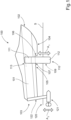
- FIG. 1 shows a side view of a schematically illustrated marine vessel 100 comprising a hull 101 provided with a hydrofoil system according to the invention.
- the hydrofoil system in this example comprises a pair of foldable hydrofoils 109, 110 which are pivoted relative to the marine vessel.
- a first hydrofoil 110 is visible, while a second hydrofoil 109 (arrow in dashed lines) is located on the opposite side of the hull 101.
- Each hydrofoil 109, 110 is controllable by at least one actuator (see Fig.9 , "930") for displacement of the foldable hydrofoils 109, 110 in a lateral direction of the marine vessel between a stowed position and a deployed position, as indicated by the arrow A1.
- FIG. 1 shows the hydrofoils 109, 110 in the deployed position, with the hull lifted out of the water 120.
- Each foldable hydrofoil comprises a first portion 111 comprising an upper end mounted by a hinge 113 relative to the hull above the water line on opposite sides of the marine vessel.
- the hinge 113 is pivoted about an axis parallel to the longitudinal axis of the vessel.
- Each first portion 111 extends adjacent the hull between the upper end and the water line of the marine vessel when the hydrofoil is in the stowed position (see Fig.3A ).
- Each foldable hydrofoil 109, 110 further comprise a second portion 112 comprising a free second end extending under the hull.
- the second portion 112 is submerged and arranged in a lateral recess 107 behind a stepped hull portion 106 of the marine vessel when the hydrofoil is in the stowed position.
- the hull 101 comprises a bow section 104 extending rearwards from the bow 102 to the stepped hull portion 106 and a stern section 105 extending rearwards from the stepped hull portion 106 to the stern 103.
- Figure 1 further shows a schematically indicated drive unit 121 connected to the stern 103 by an actuating means 122 that can adjust the position of the drive unit 121 in the vertical direction, as shown by arrow A2.
- the drive unit 121 is adjusted vertically together with the hydrofoils 109, 110 in order to maintain it submerged.
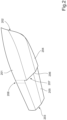
- Figure 2 shows a schematically illustrated vessel with a stepped hull.
- Figure 2 shows a hull 201 comprising a bow section 204 extending rearwards from the bow 202 to a stepped hull portion 206 and a stern section 205 extending rearwards from the stepped hull portion 206 to the stern 203.
- the stepped hull portion 206 is a break or lateral recess 207 in the hull 204 intended to reduce the wetted surface of the hull.
- Such steps can run straight across the hull (as shown in Fig.2 ) or can be V-shaped, with the vertex facing forward or rearward.
- Figure 2 further shows an optional recess 208 in the side of the hull 104. This recess 208 extending above the water line and can be provided to accommodate the first portion of a hydrofoil (not shown) in order to further reduce drag.
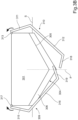
- Figure 3A-C show a schematic illustration of a hydrofoil system according to the invention and how it is deployed.
- Figure 3A shows a cross-sectional rear view through the hull 301 and a pair of hydrofoils 309, 310 located in their stowed positions.
- Each foldable hydrofoil comprises a first portion 311, 315 comprising an upper end mounted by a hinge 313, 317 relative to the hull 301 above the water line on opposite sides of the marine vessel.
- Each first portion 311, 315 extends adjacent the hull between the upper end and the water line of the marine vessel.
- Each foldable hydrofoil 309, 310 further comprise a second portion 312, 316 comprising a free second end 318, 319 extending under the hull past the central longitudinal axis P.
- the second portions 312, 316 are submerged and arranged in a lateral recess behind a stepped hull portion 306 separating a bow section 304 and a stern section 305 of the hull 301 of the marine vessel.
- both hydrofoils 309, 310 are located inside the outer envelope, or rearward extension, of the bow section 304 of the hull. In this way, the hydrofoils avoids causing an increased drag in the water flowing past the bow section 304 and the stepped hull portion 306 when travelling at relatively low speeds.
- Figure 3B shows an initial stage of the deployment of the foldable hydrofoils 309, 310.
- an actuator (not shown) causes the hydrofoils to be rotated about their respective hinges 313, 317, as indicated by arrows in Figure 3B .
- the outermost hydrofoil 310 is deployed first, followed by the innermost hydrofoil 309.
- Figure 3C shows the foldable hydrofoils 309, 310 in their fully deployed, operational positions, when the vessel is travelling a speed sufficient for creating a lifting force that lifts the entire hull 301 above the surface of the water S.
- the vessel In the deployed position, the vessel is mainly supported by the submerged parts of the second portions 318, 319 of the hydrofoils 309, 310.
- the stern of the vessel will be supported by an additional lifting force provided by the drive unit (not shown), which can comprise separate hydrofoil surfaces.
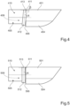
- Figure 4 shows a schematic side view of a first example of the hydrofoil system.
- Figure 4 shows a hull 401 comprising a stepped hull portion 406 separating a bow section 404 and a stern section 405 of the hull 401 of the marine vessel.
- the figure shows one hydrofoil 410 comprising an upper, first portion 411 and a lower, second portion 412.
- An identical hydrofoil is mounted on the opposite side of the hull 401.
- the hydrofoil 410 is in its stowed position and is mounted by a hinge 413 placed at an angle ⁇ relative to the horizontal plane.
- the angle of at least the first portion 411 of the hydrofoil 410 can be selected independently of the angle of the hinge 413.
- the angle of the first portion of the hydrofoil can be selected to conform to the cross-sectional shape of stepped hull portion, above and/or below the water line.
- the angle of the first portion of the hydrofoil can be selected independently of the angle of the hinge supporting each hydrofoil. This arrangement will require a corresponding angle ⁇ between the first and second portions 411, 412 of the hydrofoil with the angled hinge, in order to place its submerged second portion in a substantially horizontal position for generating a sufficient lifting force.
- Figure 5 shows a schematic side view of a second example of the hydrofoil system.
- Figure 5 shows a hull 501 comprising a stepped hull portion 506 separating a bow section 504 and a stern section 505 of the hull 501 of the marine vessel.
- the figure shows one hydrofoil 510 comprising an upper, first portion 511 and a lower, second portion 512.
- An identical hydrofoil is mounted on the opposite side of the hull 501.
- the hydrofoil 510 is in its stowed position and is mounted by a hinge 513 placed in the horizontal plane, corresponding to an angle ⁇ of 0° compared to Figure 4 .
- the first portion 511 extends at right angles to the axis of the horizontal hinge 513, corresponding to an angle ⁇ at right angles to the water line.
- Figure 7 shows a schematic lower view of the hydrofoil system in Figure 5 .
- Figure 7 shows a hull comprising a stepped hull portion 706 separating a bow section 704 and a stern section 705 of the hull of the marine vessel.
- the hydrofoil system comprises a first hydrofoil 710 having a first portion 711 and a second portion 712 and a second hydrofoil 709 having a first portion 715 and a second portion 716.
- the second portions 712, 716 have free end portions 718, 719 extending past the longitudinal axis L of the vessel in an overlapping relationship.
- first portions 711, 715 of the overlapping first and second hydrofoils 710, 709 comprise a hinges ( Fig.5 ; "513") having pivot axes extending in the horizontal plane in the longitudinal direction of the marine vessel.
- the overlapping hydrofoils 710, 709 are arranged to be displaced sequentially when moved towards their operative positions, wherein the outermost, first hydrofoil 710 is actuated first (see Fig.3B ) followed by the innermost hydrofoil 709.
- the hydrofoils are actuated in reverse, wherein the innermost hydrofoil 709 is actuated first.
- Figure 6 shows a schematic side view of a third example of the hydrofoil system.
- Figure 6 shows a hull 601 comprising a stepped hull portion 606 separating a bow section 604 and a stern section 605 of the hull 601 of the marine vessel.
- the figure shows a first hydrofoil 610 comprising an upper, first portion 611 and a lower, second portion 612.
- first hydrofoil 610 is in its stowed position and is mounted by a hinge 613 placed at an angle ⁇ relative to the horizontal plane.
- second hydrofoil 609 comprising an upper, first portion 615 and a lower, second portion 616.
- the hydrofoil 610 is in its stowed position and is mounted by a hinge 613 placed in the horizontal plane.
- Figure 6 shows a schematic lower view of the underside of the hydrofoil system in Figure 6 .
- Figure 8 shows a hull comprising a stepped hull portion 806 separating a bow section 804 and a stern section 805 of the hull of the marine vessel.
- the hydrofoil system comprises a first hydrofoil 810 having a first portion 811 and a second portion 812 and a second hydrofoil 809 having a first portion 815 and a second portion 816.
- the second portions 812, 816 have free end portions 818, 819 extending past the longitudinal axis L of the vessel in a side-by-side relationship.
- the first portion 811 of the first hydrofoil 810 in the side-by-side arrangement comprises a hinge ( Fig.6 ; "613") having a pivot axis extending at an angle to the horizontal plane in the longitudinal direction of the marine vessel.
- the first portion 815 of the second hydrofoil 809 comprises a hinge (see Fig.5 ) having a pivot axis extending in the horizontal plane in the longitudinal direction of the marine vessel.
- each hydrofoil 810, 809 in the longitudinal direction of the vessel can be reduced or eliminated when each hydrofoil reaches its operative position.
- This effect is achieved by the angled hinge, which causes the second portion 812 of the first hydrofoil 810 to be displaced rearwards relative its stowed longitudinal position. Consequently, the generated moment requiring a steering correction in order to maintain the vessel on a straight heading can be reduced or eliminated.
- This arrangement will require a corresponding angle between the first and second portions of the hydrofoil with the angled hinge, in order to place its submerged second portion in a substantially horizontal position for generating a sufficient lifting force.
- Alternative solutions can include angling the hinge of the second hydrofoil in the opposite direction, or to provide means for longitudinal displacement for one or both hydrofoils.
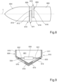
- Figure 9 shows a schematic illustration of an actuator for controlling a hydrofoil system according to the invention.
- Figure 9 shows a cross-sectional rear view through the hull 901 and a pair of hydrofoils 909, 910 located in their stowed positions.
- Each foldable hydrofoil comprises a first portion 911, 915 comprising an upper end mounted by a hinge (see Fig.3A ) relative to the hull 901 above the water line on opposite sides of the marine vessel.
- Each first portion 911, 915 extends adjacent the hull between the upper end and the water line of the marine vessel.
- Each foldable hydrofoil 909, 910 further comprises a second portion 912, 916 comprising a free second end 918, 919 extending under the hull past its central longitudinal axis.
- the second portions 912, 916 are submerged and arranged in a lateral recess behind a stepped hull portion in the hull 301 of the marine vessel.
- the hydrofoils 909, 910 are connected to an actuator 930 arranged within the hull 901 of the marine vessel, which actuator are arranged to displace the hydrofoils between their stowed and deployed positions (see Fig.3C ).
- Figure 9 shows a single, common actuator for displacement of the hydrofoils.
- each hydrofoil can be connected to at least one actuator arranged within the hull of the marine vessel, which actuator is arranged to displace the hydrofoils between their stowed and fully deployed positions.
- the size and number of actuators is dependent on the force required to deploy and maintain the hydrofoils in their operative positions. Consequently, the hydrofoils can be operated by a single, common actuator, or by one or more actuators for each hydrofoil.
- the at least one actuator is arranged below the water line within the hull of the marine vessel.
- the at least one actuator is preferably arranged below the water line within the hull of the marine vessel.
- vessels may comprise fixed hydrofoils or hydrofoils with control surfaces as indicated in the background. Although no such features are described in the above examples, the invention is applicable to both types of hydrofoils.
Landscapes
- Physics & Mathematics (AREA)
- Fluid Mechanics (AREA)
- Chemical & Material Sciences (AREA)
- Engineering & Computer Science (AREA)
- Combustion & Propulsion (AREA)
- Mechanical Engineering (AREA)
- Ocean & Marine Engineering (AREA)
- Other Liquid Machine Or Engine Such As Wave Power Use (AREA)
Description
- The present invention relates to a foldable hydrofoil system and a marine vessel with such a system.
- Known hydrofoil boats are usually provided with at least one hydrofoil consisting of a wing like structure mounted on struts below the hull, or across the keels of a catamaran in a variety of boats. A hydrofoil operates in the same way as a wing-shaped airfoil to create a lifting force and can have a similar cross-section. As a hydrofoil-equipped watercraft increases in speed, the hydrofoil elements below the hull develop enough lift to raise the hull out of the water, which greatly reduces hull drag. This provides a corresponding increase in speed and fuel efficiency, as less propulsive force is required to drive the vessel.
- When used as a lifting element on a hydrofoil boat, the upward force exerted by the hydrofoil lifts the body of the vessel clear of the water, thereby decreasing drag of the hull and increasing the speed of the vessel. The lifting force eventually balances with the weight of the craft, reaching a point where the hydrofoil no longer lifts out of the water but remains in equilibrium. Since wave resistance and other impeding forces such as various types of drag on the hull are eliminated as the hull lifts clear, turbulence and drag act increasingly on the much smaller surface area of the hydrofoil, and decreasingly on the relative larger area of the hull, creating a marked increase in speed. In the case of fixed hydrofoils, the lifting force will be dependent on the speed of the vessel. Alternatively, hydrofoils can be provided with control surfaces in the same way as an aircraft wing, whereby the control surfaces can be angled to increase or decrease the lifting force. Once the hull is lifted clear of the water, the effect of the reduced drag can be used for increased speed, while maintaining the output of the propulsion system. Alternatively, the reduced drag can be used for increased fuel economy, while reducing the output of the propulsion system to a lower level once the hull is lifted clear of the water.
-
US 4 335 671 discloses a vessel comprising fixed hydrofoils. A problem with this solution is the increased draft created by the hydrofoils which makes it impossible for these vessels to navigate in shallow waters. A further problem is the increased drag experienced by fixed hydrofoil vessels when travelling at speeds where the hull is in contact with the water. - According to its abstract,
EP 0 240 472 B1 relates to a variable geometry hydrofoil boat, equipped for this purpose with secant foils supported by articulated arms operated automatically or manually. The boat makes it possible to obtain a craft which, depending on operational requirements, may function either in the 'totally submerged foil' mode or in the 'secant foil' mode, that is to say with a variable foil surface. The secant foils supported by arms articulated to the hull may, in a variant of the embodiment, also be applied to fastmoving and streamlined naval units of the semi-planing type, for the purpose of damping their rolling and pitching movements. - Various solutions have been suggested to overcome the above problems relating to drag and draft.
US 2 984 197 discloses a vessel comprising hydrofoils which are retractable into contact with the hull of the vessel. A problem with this solution is that the retracted hydrofoils extend outside the envelope of the submerged hull when the hydrofoils are stowed. Compared to fixed hydrofoil vessels, the draft is reduced but the drag created by the retracted hydrofoils at low speed is still substantial. - The invention provides an improved hydrofoil system aiming to solve the above-mentioned problems.
- An object of the invention is to provide a foldable hydrofoil system for a vessel, which system solves the above-mentioned problems.
- The object is achieved by a marine vessel comprising a hydrofoil system according to the appended claims.
- In the subsequent text, the term "water line" is defined as the level around the hull reached by the surrounding water when the vessel is at rest. The term "longitudinal axis" is defined as an axis extending between the bow and the stern of the vessel in line with the keel. With respect to the foldable hydrofoils, the term "stowed position" refers to a position where the hydrofoils are inoperative and fully retracted. Similarly, the term "deployed position" refers to a position where the hydrofoils are operative and fully deployed. The subsequent text also refers to a "stepped hull". A stepped hull can comprise one or more steps and is a known design feature on the hull bottom of a planing hull of high speed marine vessels. Said step or steps are breaks in the hull intended to reduce the amount of hull surface in contact with the water, i.e. the wetted hull surface. Steps can run straight across the hull or can be V-shaped, with the vertex facing forward or aft. They usually have large apertures on the outboard side of the hull to allow air to be sucked down below the hull into the step in order to ventilate the step.
- The invention relates to a marine vessel comprising a hull and a hydrofoil system. The hydrofoil system comprises at least one pair of foldable hydrofoils which are pivoted relative to the hull of the marine vessel, wherein each hydrofoil is controllable by at least one actuator for displacement of the at least one pair of foldable hydrofoils in a lateraldirection of the marine vessel between a stowed position and a fully deployed or operative position. In this context, the term "lateral direction" is defined to include a transverse direction relative to the central longitudinal axis of the marine vessel, i.e. at right angles to said longitudinal axis, as well as a substantially transverse direction. A substantially transverse direction intersects the longitudinal axis of the vessel and can be angled up to about 5° rearwards from the transverse direction.
- Each foldable hydrofoil comprises a first portion comprising an upper end mounted hinged relative to the hull above the water line on opposite sides of the marine vessel relative to each other. Further, each first portion extends adjacent the hull between the upper end and the water line of the marine vessel when the hydrofoil is in the stowed position. Each foldable hydrofoil comprises a second portion comprising a free second end extending under the hull and under the water line of the marine vessel when the hydrofoil is in the stowed position. The submerged second portion of the respective hydrofoil is arranged in a lateral recess behind a stepped hull portion of the marine vessel when the hydrofoil is in the stowed position.
- According to the invention, at least the submerged portions of the hydrofoils are located in the lateral recess behind the stepped hull portion of the marine vessel when the hydrofoils are in the stowed position. Hence, if the stepped portion extends above the waterline when the vessel is stationary, at least a lower part of the first portion can be located in the lateral recess behind the stepped hull portion.
- A lower outer surface of each hydrofoil is at least flush with the submerged outer surface of the hull in front of the stepped hull portion when the hydrofoil is in the stowed position. In this context, an outer surface of the hydrofoil faces away from the outer surface of the hull. By locating the stowed hydrofoils so that their outer surfaces are flush with or inside the envelope of the outer hull surface immediately in front of the step in the hull, it is possible to virtually eliminate any drag from the stowed hydrofoils when the vessel is travelling at low or planing speeds. In order to reduce drag as well as air resistance, an outer side surface of each hydrofoil can be located in a recess in the side of the hull above the water line when the hydrofoil is in the stowed position. The recesses in the opposite sides of the hull can form a continuation of the submerged stepped hull portion. In the latter case, both the first and the second portions of the hull can be located in a step or a recess in the hull.
- Each hydrofoil comprises a single structural component having a generally angled wing shape. The shape of the hydrofoil conforms to the outer surface of the hull at least below and preferably also above the water line. In this way at least the submerged portion of the hydrofoil conforms with and is located at least flush with the outer surface of an adjacent portion of the hull. This is achieved by giving the outer surface of each hydrofoil the same cross-sectional shape as the outer surface of the hull immediately in front of the respective stowed hydrofoil. In this example, the cross-sections are taken at right angles to the longitudinal axis of the vessel.
- The first end of each foldable hydrofoil comprises a hinge having parallel or near parallel pivot axes extending in the longitudinal direction of the marine vessel, in a plan view of the vessel. The hinges allow the hydrofoils to be pivoted away from the hull of the vessel, so that they can provide a lifting force sufficient to lift the hull clear of the water. Simultaneously, one or more drive units for propelling the vessel are extended downwards to allow the drive units to remain submerged as the hull of the vessel is lifted out of the water by the hydrofoils with increasing speed.
- The second end of the hydrofoils extends at least up to the central longitudinal axis of the marine vessel when the hydrofoils are in their stowed positions. Hydrofoils according to this example can be suited for smaller and/or relatively light vessels, requiring a correspondingly smaller lifting force to make the hull clear the surface of the water.
- Preferably, the second ends of each pair of hydrofoils are arranged to extend a predetermined distance past the central longitudinal axis of the marine vessel. Hydrofoils according to this example are suited for larger and/or relatively heavy vessels, requiring a correspondingly larger lifting force to make the hull clear the surface of the water. According to one example, the second ends of each pair of hydrofoils are arranged to overlap below the keel of the vessel when the hydrofoils are in the stowed position. When the hydrofoils overlap in the lateral direction of the vessel, the recessed portion of the stepped hull should have a recessed depth sufficient for accommodating the second ends of the hydrofoils in the stowed position. Alternatively, or in combination, the thickness of the overlapping hydrofoils sections can be selected to fit in the stepped hull portion. During deployment, the overlapping hydrofoils are arranged to be displaced sequentially when moved towards their operative positions, wherein the outermost hydrofoil is actuated first. During retraction of the hydrofoils towards the stowed position the hydrofoils are actuated in reverse, wherein the innermost hydrofoil is actuated first.
- When the hydrofoils are arranged to overlap below the keel of the vessel the first end of both foldable hydrofoils comprise a hinge having a pivot axis extending in the horizontal plane in the longitudinal direction of the marine vessel. In this way the hydrofoils are deployed symmetrically in the lateral direction and do not cause a moment about the center of gravity of the vessel requiring a steering correction.
- According to a further example, the second ends of each pair of hydrofoils are arranged to extend side-by-side adjacent the hull, in the longitudinal direction thereof, when the hydrofoils are in the stowed position. As the hydrofoils do not overlap in the lateral direction of the vessel, the recessed portion of the stepped hull requires a relatively small recessed depth for accommodating the second ends of the hydrofoils in the stowed position. This arrangement can allow the use of a standard hull as the stepped hull portion provided has a sufficient recessed depth for the longitudinally offset hydrofoils. During deployment, the overlapping hydrofoils are arranged to be displaced simultaneously when moved towards the fully deployed, operative position, as the hydrofoils do not interfere with each other during the displacement. When retracting the hydrofoils towards the stowed position the hydrofoils are simply actuated in reverse.
- In the example where the stowed hydrofoils are side-by-side adjacent the hull, the first ends of both foldable hydrofoils can comprise a hinge having a pivot axis extending in the horizontal plane in the longitudinal direction of the marine vessel. When these hydrofoils are deployed, the submerged second ends of each hydrofoil will be offset in the longitudinal direction of the vessel when each hydrofoil reaches its operative position. As the hydrofoils are deployed non-symmetrically, or offset in the lateral direction, a moment is generated about the center of gravity of the vessel. This moment will require a steering correction in order to maintain the vessel on a straight heading.
- Alternatively, the first end of one of the hydrofoils in a side-by-side arrangement can comprise one of the hinges having a pivot axis extending at an angle to the horizontal plane in the longitudinal direction of the marine vessel. When the hydrofoils are deployed, the offset between the submerged second ends of each hydrofoil in the longitudinal direction of the vessel can be reduced or eliminated when each hydrofoil reaches its operative position. Consequently, the generated moment requiring a steering correction in order to maintain the vessel on a straight heading can be reduced or eliminated. This arrangement will require a corresponding angle between the first and second portions of the hydrofoil with the angled hinge, in order to place its submerged second portion in a substantially horizontal position for generating a sufficient lifting force. The angled transition between the first and second portions can be in the shape of a distinct line or a twisted curve, depending on the cross-sectional shape of the hull
- According to a further alternative, the first end of one of the hydrofoils in a side-by-side arrangement can comprise hinges having pivot axis extending at an angles placed in equal and opposite directions relative to the horizontal plane in the longitudinal direction of the marine vessel.
- According to a further alternative, the first ends of both foldable hydrofoils can comprise a hinge having a pivot axis extending in the horizontal plane in the longitudinal direction of the marine vessel. As the hydrofoils are deployed, the offset between the submerged second ends of each hydrofoil in the longitudinal direction of the vessel can be reduced or eliminated by displacing one or both hydrofoils in the longitudinal direction of the vessel. When the hydrofoils reach their operative positions, both hydrofoils can be arranged symmetrically in the lateral direction and do not cause a moment about the center of gravity of the vessel requiring a steering correction.
- Independently of the angle of the hinge supporting each hydrofoil, at least the first portion of each hydrofoil can extend downwards at right angles to the water line when the hydrofoil is in the stowed position. Alternatively, at least the first portion can extend at a predetermined angle to the water line, in a downward and rearward direction, when the hydrofoil is in the stowed position. The angle of the first portion of the hydrofoil can be selected to conform to the cross-sectional shape of stepped hull portion, above and/or below the water line
- The hydrofoil system according to the invention can be operated between the stowed and operative positions by means of one or more electric or hydraulic actuators. Each hydrofoil can be connected to at least one actuator arranged within the hull of the marine vessel, which actuator is arranged to displace the hydrofoils between their stowed and fully deployed positions. The size and number of actuators is dependent on the force required to deploy and maintain the hydrofoils in their operative positions. Consequently, the hydrofoils can be operated by a single, common actuator, or by one or more actuators for each hydrofoil. According to one example, the at least one actuator is arranged below the water line within the hull of the marine vessel.
- The arrangement according to the invention solves the problem of increased draft as encounter by vessels comprising fixed hydrofoils, which makes it impossible for these vessels to access shallow ports or to navigate rivers. The invention also solves the problem of increased drag experienced by fixed hydrofoil vessels when travelling at speeds where the hull is in contact with the water.
- With respect to vessels with folding hydrofoils, the invention solves the problem of increased draft experienced by folding hydrofoil vessels when travelling at speeds where the hull is in contact with the water. Known vessels of this type are provided with hydrofoils which either extend outside the envelope of the submerged hull or protrude above or inside the upper portions of the hull when the hydrofoils are stowed and not in use. The solution according to the invention provides a compact arrangement that does not create undesired drag or require excessive space for the stowed hydrofoils, while also providing a lifting force sufficient for lifting the vessel out of the water when fully deployed.
- Further advantages and advantageous features of the invention are disclosed in the following description and in the dependent claims.
- With reference to the appended drawings, below follows a more detailed description of embodiments of the invention cited as examples. In the drawings:
- Fig. 1
- shows a side view of a schematically illustrated vessel comprising a hydrofoil system according to the invention;
- Fig. 2
- shows a schematically illustrated vessel with a stepped hull;
- Fig. 3A-C
- show a schematic illustration of a hydrofoil system according to the invention and how it is deployed;
- Fig. 4
- shows a schematic side view of a first example of the hydrofoil system;
- Fig. 5
- shows a schematic side view of a second example of the hydrofoil system;
- Fig. 6
- shows a schematic side view of a third example of the hydrofoil system;
- Fig. 7
- shows a schematic lower view of the hydrofoil system in
Figs. 4 and 5 ; - Fig. 8
- shows a schematic lower view of the hydrofoil system in
Fig. 6 ; and - Fig. 9
- shows a schematic illustration of an actuator for controlling a hydrofoil system according to the invention.
-
Figure 1 shows a side view of a schematically illustratedmarine vessel 100 comprising ahull 101 provided with a hydrofoil system according to the invention. The hydrofoil system in this example comprises a pair offoldable hydrofoils first hydrofoil 110 is visible, while a second hydrofoil 109 (arrow in dashed lines) is located on the opposite side of thehull 101. Eachhydrofoil Fig.9 , "930") for displacement of thefoldable hydrofoils Figure 1 shows thehydrofoils water 120. Each foldable hydrofoil comprises afirst portion 111 comprising an upper end mounted by ahinge 113 relative to the hull above the water line on opposite sides of the marine vessel. In this example, thehinge 113 is pivoted about an axis parallel to the longitudinal axis of the vessel. Eachfirst portion 111 extends adjacent the hull between the upper end and the water line of the marine vessel when the hydrofoil is in the stowed position (seeFig.3A ). Eachfoldable hydrofoil second portion 112 comprising a free second end extending under the hull. Thesecond portion 112 is submerged and arranged in alateral recess 107 behind a steppedhull portion 106 of the marine vessel when the hydrofoil is in the stowed position. As shown inFigure 1 , thehull 101 comprises abow section 104 extending rearwards from thebow 102 to the steppedhull portion 106 and astern section 105 extending rearwards from the steppedhull portion 106 to the stern 103.Figure 1 further shows a schematically indicateddrive unit 121 connected to the stern 103 by an actuating means 122 that can adjust the position of thedrive unit 121 in the vertical direction, as shown by arrow A2. Thedrive unit 121 is adjusted vertically together with thehydrofoils -
Figure 2 shows a schematically illustrated vessel with a stepped hull.Figure 2 shows ahull 201 comprising abow section 204 extending rearwards from thebow 202 to a steppedhull portion 206 and astern section 205 extending rearwards from the steppedhull portion 206 to the stern 203. The steppedhull portion 206 is a break orlateral recess 207 in thehull 204 intended to reduce the wetted surface of the hull. Such steps can run straight across the hull (as shown inFig.2 ) or can be V-shaped, with the vertex facing forward or rearward.Figure 2 further shows anoptional recess 208 in the side of thehull 104. Thisrecess 208 extending above the water line and can be provided to accommodate the first portion of a hydrofoil (not shown) in order to further reduce drag. -
Figure 3A-C show a schematic illustration of a hydrofoil system according to the invention and how it is deployed.Figure 3A shows a cross-sectional rear view through thehull 301 and a pair ofhydrofoils first portion hinge hull 301 above the water line on opposite sides of the marine vessel. Eachfirst portion foldable hydrofoil second portion second end second portions hull portion 306 separating abow section 304 and astern section 305 of thehull 301 of the marine vessel. As indicated inFigure 3A , bothhydrofoils bow section 304 of the hull. In this way, the hydrofoils avoids causing an increased drag in the water flowing past thebow section 304 and the steppedhull portion 306 when travelling at relatively low speeds. -
Figure 3B shows an initial stage of the deployment of thefoldable hydrofoils respective hinges Figure 3B . As shown in this example, theoutermost hydrofoil 310 is deployed first, followed by theinnermost hydrofoil 309. -
Figure 3C shows thefoldable hydrofoils entire hull 301 above the surface of the water S. In the deployed position, the vessel is mainly supported by the submerged parts of thesecond portions hydrofoils -
Figure 4 shows a schematic side view of a first example of the hydrofoil system.Figure 4 shows ahull 401 comprising a steppedhull portion 406 separating abow section 404 and astern section 405 of thehull 401 of the marine vessel. The figure shows onehydrofoil 410 comprising an upper,first portion 411 and a lower,second portion 412. An identical hydrofoil is mounted on the opposite side of thehull 401. In this example, thehydrofoil 410 is in its stowed position and is mounted by ahinge 413 placed at an angle β relative to the horizontal plane. The angle of at least thefirst portion 411 of thehydrofoil 410 can be selected independently of the angle of thehinge 413. However, inFigure 4 thefirst portion 411 extends at right angles to the axis of theangled hinge 413, corresponding to an angle α relative to the water line, where α = 90°- β. Within the scope of the invention, the angle of the first portion of the hydrofoil can be selected to conform to the cross-sectional shape of stepped hull portion, above and/or below the water line. Hence, the angle of the first portion of the hydrofoil can be selected independently of the angle of the hinge supporting each hydrofoil. This arrangement will require a corresponding angle β between the first andsecond portions -
Figure 5 shows a schematic side view of a second example of the hydrofoil system.Figure 5 shows ahull 501 comprising a steppedhull portion 506 separating abow section 504 and astern section 505 of thehull 501 of the marine vessel. The figure shows onehydrofoil 510 comprising an upper,first portion 511 and a lower,second portion 512. An identical hydrofoil is mounted on the opposite side of thehull 501. In this example, thehydrofoil 510 is in its stowed position and is mounted by ahinge 513 placed in the horizontal plane, corresponding to an angle β of 0° compared toFigure 4 . Further, thefirst portion 511 extends at right angles to the axis of thehorizontal hinge 513, corresponding to an angle α at right angles to the water line. -
Figure 7 shows a schematic lower view of the hydrofoil system inFigure 5 .Figure 7 shows a hull comprising a steppedhull portion 706 separating abow section 704 and astern section 705 of the hull of the marine vessel. The hydrofoil system comprises afirst hydrofoil 710 having afirst portion 711 and asecond portion 712 and asecond hydrofoil 709 having afirst portion 715 and asecond portion 716. Thesecond portions free end portions first portions second hydrofoils Fig.5 ; "513") having pivot axes extending in the horizontal plane in the longitudinal direction of the marine vessel. - During deployment, the overlapping
hydrofoils first hydrofoil 710 is actuated first (seeFig.3B ) followed by theinnermost hydrofoil 709. During retraction of the hydrofoils towards the stowed position the hydrofoils are actuated in reverse, wherein theinnermost hydrofoil 709 is actuated first. -
Figure 6 shows a schematic side view of a third example of the hydrofoil system.Figure 6 shows ahull 601 comprising a steppedhull portion 606 separating abow section 604 and astern section 605 of thehull 601 of the marine vessel. The figure shows afirst hydrofoil 610 comprising an upper,first portion 611 and a lower,second portion 612. In this example, thefirst hydrofoil 610 is in its stowed position and is mounted by ahinge 613 placed at an angle β relative to the horizontal plane. The figure further showssecond hydrofoil 609 comprising an upper,first portion 615 and a lower,second portion 616. In this example, thehydrofoil 610 is in its stowed position and is mounted by ahinge 613 placed in the horizontal plane. - The arrangement shown in
Figure 6 can be used for the example inFigure 8 , which shows a schematic lower view of the underside of the hydrofoil system inFigure 6 .Figure 8 shows a hull comprising a steppedhull portion 806 separating abow section 804 and astern section 805 of the hull of the marine vessel. The hydrofoil system comprises afirst hydrofoil 810 having afirst portion 811 and asecond portion 812 and asecond hydrofoil 809 having afirst portion 815 and asecond portion 816. Thesecond portions free end portions first portion 811 of thefirst hydrofoil 810 in the side-by-side arrangement comprises a hinge (Fig.6 ; "613") having a pivot axis extending at an angle to the horizontal plane in the longitudinal direction of the marine vessel. However, thefirst portion 815 of thesecond hydrofoil 809 comprises a hinge (seeFig.5 ) having a pivot axis extending in the horizontal plane in the longitudinal direction of the marine vessel. - When the hydrofoils are deployed, the side-by-side offset between the submerged second ends 818, 819 of each
hydrofoil second portion 812 of thefirst hydrofoil 810 to be displaced rearwards relative its stowed longitudinal position. Consequently, the generated moment requiring a steering correction in order to maintain the vessel on a straight heading can be reduced or eliminated. This arrangement will require a corresponding angle between the first and second portions of the hydrofoil with the angled hinge, in order to place its submerged second portion in a substantially horizontal position for generating a sufficient lifting force. - Alternative solutions can include angling the hinge of the second hydrofoil in the opposite direction, or to provide means for longitudinal displacement for one or both hydrofoils.
-
Figure 9 shows a schematic illustration of an actuator for controlling a hydrofoil system according to the invention.Figure 9 shows a cross-sectional rear view through thehull 901 and a pair ofhydrofoils first portion Fig.3A ) relative to thehull 901 above the water line on opposite sides of the marine vessel. Eachfirst portion foldable hydrofoil second portion second end second portions hull 301 of the marine vessel. Thehydrofoils actuator 930 arranged within thehull 901 of the marine vessel, which actuator are arranged to displace the hydrofoils between their stowed and deployed positions (seeFig.3C ). -
Figure 9 shows a single, common actuator for displacement of the hydrofoils. However, each hydrofoil can be connected to at least one actuator arranged within the hull of the marine vessel, which actuator is arranged to displace the hydrofoils between their stowed and fully deployed positions. The size and number of actuators is dependent on the force required to deploy and maintain the hydrofoils in their operative positions. Consequently, the hydrofoils can be operated by a single, common actuator, or by one or more actuators for each hydrofoil. According to one example, the at least one actuator is arranged below the water line within the hull of the marine vessel. The at least one actuator is preferably arranged below the water line within the hull of the marine vessel. - It is to be understood that the present invention is not limited to the embodiments described above and illustrated in the drawings; rather, the skilled person will recognize that many changes and modifications may be made within the scope of the appended claims. For instance, vessels may comprise fixed hydrofoils or hydrofoils with control surfaces as indicated in the background. Although no such features are described in the above examples, the invention is applicable to both types of hydrofoils.
Claims (15)
- A marine vessel comprising a hull (101; 301) and a hydrofoil system, the hydrofoil system comprising at least one pair of foldable hydrofoils (109, 110; 309, 310) which are pivoted relative to the marine vessel, wherein each hydrofoil (109, 110; 309, 310) is controllable by at least one actuator (930) for displacement of the at least one pair of foldable hydrofoils in a lateral direction of the marine vessel between a stowed position and a deployed position, wherein- each foldable hydrofoil (109, 110; 309, 310) comprises a first portion (111; 311, 315) comprising an upper end mounted hinged relative to the hull above the water line on opposite sides of the marine vessel;
wherein each first portion (111; 311, 315) extends adjacent the hull (101; 301) between the upper end and the water line of the marine vessel when the hydrofoil is in the stowed position; and- each foldable hydrofoil comprises a second portion (112; 312, 316) comprising a free second end extending under the hull;characterised in that
the second portion (112; 312, 316) is submerged and arranged in a lateral recess (107; 307) behind a stepped hull portion (106) of the marine vessel when the hydrofoil is in the stowed position. - The marine vessel according to claim 1, characterized in that at least the submerged portions (112) of the hydrofoils (109, 110) are located in the lateral recess behind the stepped hull portion of the marine vessel when the hydrofoils are in the stowed position.
- The marine vessel according to claim 1 or 2, characterized in that a lower outer surface of each hydrofoil (109, 110) is at least flush with the submerged outer surface of the hull (101) in front of the stepped hull portion when the hydrofoils (109, 110) are in the stowed position.
- The marine vessel according to any one of claims 1-3, characterized in that an outer side surface of each hydrofoil is located in a recess (208) in the side of the hull above the water line when the hydrofoil is in the stowed position.
- The marine vessel according to any one of claims 1-4, characterized in that each hydrofoil (109, 110; 309, 310) comprises a single structural component having a shape conforming with the outer surface of the hull (101; 301) above and below the water line.
- The marine vessel according to any one of claims 1-5, characterized in that the first end of each foldable hydrofoil (109, 110; 309, 310) comprises a hinge (113; 313, 317) having parallel pivot axes extending in the longitudinal direction of the marine vessel.
- The marine vessel according to any one of claims 1-6, characterized in that the second end of each hydrofoil (109, 110; 309, 310) extends at least up to the central longitudinal axis (L) of the marine vessel.
- The marine vessel according to claim 7, characterized in that that the second ends of each pair of hydrofoils (109, 110; 309, 310) are arranged to extend a predetermined distance past the central longitudinal axis (L) of the marine vessel.
- The marine vessel according to claim 8, characterized in that the second ends of each pair of hydrofoils (709, 710) are arranged to overlap when the hydrofoils are in the stowed position.
- The marine vessel according to claim 9, characterized in that the overlapping hydrofoils (709, 710) are arranged to be displaced sequentially when moved towards the deployed position.
- The marine vessel according to claim 8, characterized in that the second ends of each pair of hydrofoils (809, 810) are arranged to extend side-by-side adjacent the hull when the hydrofoils are in the stowed position.
- The marine vessel according to claim 11, characterized in that the first end of one of the foldable hydrofoils (610) comprises a hinge (613) having a pivot axis extending at an angle (β) to the horizontal plane in the longitudinal direction of the marine vessel.
- The marine vessel according to any one of claims 1-12, characterized in that each first portion extends downwards at right angles to the water line when the hydrofoil is in the stowed position.
- The marine vessel according to any one of claims 1-12, characterized in that each first portion extends downwards and rearwards at a predetermined angle (α) to the water line when the hydrofoil is in the stowed position
- The marine vessel according to any one of claims 1-14, characterized in that each hydrofoil is connected to at least one actuator (930) arranged within the hull of the marine vessel, wherein the at least one actuator is arranged to displace the hydrofoils between their stowed and deployed positions, preferably the at least one actuator are arranged below the water line within the hull of the marine vessel.
Applications Claiming Priority (1)
| Application Number | Priority Date | Filing Date | Title |
|---|---|---|---|
| PCT/EP2019/072138 WO2021032277A1 (en) | 2019-08-19 | 2019-08-19 | Hydrofoil system and marine vessel |
Publications (3)
| Publication Number | Publication Date |
|---|---|
| EP4017793A1 EP4017793A1 (en) | 2022-06-29 |
| EP4017793C0 EP4017793C0 (en) | 2024-08-14 |
| EP4017793B1 true EP4017793B1 (en) | 2024-08-14 |
Family
ID=67688779
Family Applications (1)
| Application Number | Title | Priority Date | Filing Date |
|---|---|---|---|
| EP19756173.1A Active EP4017793B1 (en) | 2019-08-19 | 2019-08-19 | Hydrofoil system and marine vessel |
Country Status (3)
| Country | Link |
|---|---|
| US (1) | US11738827B2 (en) |
| EP (1) | EP4017793B1 (en) |
| WO (1) | WO2021032277A1 (en) |
Families Citing this family (6)
| Publication number | Priority date | Publication date | Assignee | Title |
|---|---|---|---|---|
| CN114787027A (en) | 2019-12-10 | 2022-07-22 | 沃尔沃遍达公司 | Hull unit with hydrofoil system and ship |
| US11667352B2 (en) * | 2020-04-16 | 2023-06-06 | MHL Custom, Inc. | Foiling watercraft |
| IT202100024302A1 (en) * | 2021-09-22 | 2023-03-22 | Davide Degennaro | BOAT WITH TILTING FOILS KEEL |
| JP2023131734A (en) * | 2022-03-09 | 2023-09-22 | ヤマハ発動機株式会社 | Outboard motors and ships |
| IT202200014074A1 (en) * | 2022-07-04 | 2024-01-04 | Benedetto Laura | EXTRACTION AND ADJUSTMENT MECHANISM OF A WING INTEGRATED TO THE HULL OF A BOAT |
| US12565289B2 (en) * | 2023-03-07 | 2026-03-03 | Hangzhou Sino Eagle Yacht Co., Ltd. | Retractable hydrofoil system for multi-hull vessel |
Family Cites Families (9)
| Publication number | Priority date | Publication date | Assignee | Title |
|---|---|---|---|---|
| US2984197A (en) | 1959-08-19 | 1961-05-16 | Bader John | Arrangement for hydrofoil retraction and transmission |
| US3164117A (en) * | 1962-09-19 | 1965-01-05 | Aqua Flite Hydrofoil Corp | Hydrofoil system |
| US3802369A (en) * | 1971-04-22 | 1974-04-09 | K Ishimoto | Sporting boats |
| US4335671A (en) | 1980-07-17 | 1982-06-22 | The Boeing Company | Flap leading edge for hydrofoil vessels and the like |
| IT1189741B (en) * | 1986-04-04 | 1988-02-04 | Rodriguez Spa | CONTROLLABLE GEOMETRY HYDRAULIC |
| RU2059513C1 (en) * | 1992-11-12 | 1996-05-10 | Комсомольское-на-Амуре авиационное производственное объединение | Boat |
| US6167829B1 (en) * | 1997-10-09 | 2001-01-02 | Thomas G. Lang | Low-drag, high-speed ship |
| JP4051165B2 (en) | 1999-11-01 | 2008-02-20 | ヤンマー株式会社 | Hydrofoiled ship |
| CN101712372B (en) * | 2009-09-24 | 2012-04-11 | 深圳市海斯比船艇科技股份有限公司 | Three-controllable hydrofoil planing boat |
-
2019
- 2019-08-19 US US17/597,874 patent/US11738827B2/en active Active
- 2019-08-19 EP EP19756173.1A patent/EP4017793B1/en active Active
- 2019-08-19 WO PCT/EP2019/072138 patent/WO2021032277A1/en not_active Ceased
Also Published As
| Publication number | Publication date |
|---|---|
| US11738827B2 (en) | 2023-08-29 |
| US20220250716A1 (en) | 2022-08-11 |
| EP4017793C0 (en) | 2024-08-14 |
| WO2021032277A1 (en) | 2021-02-25 |
| EP4017793A1 (en) | 2022-06-29 |
Similar Documents
| Publication | Publication Date | Title |
|---|---|---|
| US11738827B2 (en) | Hydrofoil system and marine vessel | |
| US4582011A (en) | Hydrofoil vessel | |
| US5163377A (en) | Sailing yacht | |
| US4458622A (en) | Boat having a variable hull configuration | |
| GB2309011A (en) | Monohull Water-borne Craft | |
| EP0545878B1 (en) | Multi-hull vessel | |
| US8955451B2 (en) | Foil structure for providing buoyancy and lift | |
| EP3583022A1 (en) | Powerboat | |
| JPS5893695A (en) | Single hull ship, propeller thereof is stabilized | |
| US6314900B1 (en) | High-velocity rudder | |
| JP2008515699A (en) | Improved convertible ship | |
| US6805068B1 (en) | Hydrofoil system for lifting a boat partially out of water an amount sufficient to reduce drag | |
| WO1988007468A1 (en) | Planing catamaran | |
| EP4153472B1 (en) | Hull with variable geometry | |
| US20070245943A1 (en) | Wing In Ground Effect Hydrofoil Vessel | |
| EP1472133B1 (en) | Watercraft | |
| AU2003207004A1 (en) | Watercraft | |
| EP4072935B1 (en) | Hull unit with a hydrofoil system and marine vessel | |
| GB2464768A (en) | Boat with a pivoting hydrofoil arrangement | |
| EP3050792A1 (en) | Wave piercing ship hull | |
| RU2165865C1 (en) | Planing vessel | |
| IT202100016967A1 (en) | Variable geometry hull for boats | |
| RU2781170C1 (en) | Multi-hull vessel | |
| JP2537640Y2 (en) | Submerged wing hydrofoil ship | |
| KR20250109302A (en) | Convertible type hydrofoil and ship including the same |
Legal Events
| Date | Code | Title | Description |
|---|---|---|---|
| STAA | Information on the status of an ep patent application or granted ep patent |
Free format text: STATUS: UNKNOWN |
|
| STAA | Information on the status of an ep patent application or granted ep patent |
Free format text: STATUS: THE INTERNATIONAL PUBLICATION HAS BEEN MADE |
|
| PUAI | Public reference made under article 153(3) epc to a published international application that has entered the european phase |
Free format text: ORIGINAL CODE: 0009012 |
|
| STAA | Information on the status of an ep patent application or granted ep patent |
Free format text: STATUS: REQUEST FOR EXAMINATION WAS MADE |
|
| 17P | Request for examination filed |
Effective date: 20220317 |
|
| AK | Designated contracting states |
Kind code of ref document: A1 Designated state(s): AL AT BE BG CH CY CZ DE DK EE ES FI FR GB GR HR HU IE IS IT LI LT LU LV MC MK MT NL NO PL PT RO RS SE SI SK SM TR |
|
| DAV | Request for validation of the european patent (deleted) | ||
| DAX | Request for extension of the european patent (deleted) | ||
| GRAP | Despatch of communication of intention to grant a patent |
Free format text: ORIGINAL CODE: EPIDOSNIGR1 |
|
| STAA | Information on the status of an ep patent application or granted ep patent |
Free format text: STATUS: GRANT OF PATENT IS INTENDED |
|
| RIC1 | Information provided on ipc code assigned before grant |
Ipc: B63H 20/10 20060101ALI20240228BHEP Ipc: B63B 1/28 20060101ALI20240228BHEP Ipc: B63B 1/26 20060101ALI20240228BHEP Ipc: B63B 1/20 20060101ALI20240228BHEP Ipc: B63B 1/30 20060101AFI20240228BHEP |
|
| INTG | Intention to grant announced |
Effective date: 20240322 |
|
| GRAS | Grant fee paid |
Free format text: ORIGINAL CODE: EPIDOSNIGR3 |
|
| GRAA | (expected) grant |
Free format text: ORIGINAL CODE: 0009210 |
|
| STAA | Information on the status of an ep patent application or granted ep patent |
Free format text: STATUS: THE PATENT HAS BEEN GRANTED |
|
| AK | Designated contracting states |
Kind code of ref document: B1 Designated state(s): AL AT BE BG CH CY CZ DE DK EE ES FI FR GB GR HR HU IE IS IT LI LT LU LV MC MK MT NL NO PL PT RO RS SE SI SK SM TR |
|
| REG | Reference to a national code |
Ref country code: GB Ref legal event code: FG4D |
|
| REG | Reference to a national code |
Ref country code: CH Ref legal event code: EP |
|
| REG | Reference to a national code |
Ref country code: DE Ref legal event code: R096 Ref document number: 602019057006 Country of ref document: DE |
|
| REG | Reference to a national code |
Ref country code: IE Ref legal event code: FG4D |
|
| U01 | Request for unitary effect filed |
Effective date: 20240911 |
|
| U07 | Unitary effect registered |
Designated state(s): AT BE BG DE DK EE FI FR IT LT LU LV MT NL PT RO SE SI Effective date: 20240926 |
|
| U20 | Renewal fee for the european patent with unitary effect paid |
Year of fee payment: 6 Effective date: 20241018 |
|
| PG25 | Lapsed in a contracting state [announced via postgrant information from national office to epo] |
Ref country code: NO Free format text: LAPSE BECAUSE OF FAILURE TO SUBMIT A TRANSLATION OF THE DESCRIPTION OR TO PAY THE FEE WITHIN THE PRESCRIBED TIME-LIMIT Effective date: 20241114 |
|
| PG25 | Lapsed in a contracting state [announced via postgrant information from national office to epo] |
Ref country code: PL Free format text: LAPSE BECAUSE OF FAILURE TO SUBMIT A TRANSLATION OF THE DESCRIPTION OR TO PAY THE FEE WITHIN THE PRESCRIBED TIME-LIMIT Effective date: 20240814 Ref country code: GR Free format text: LAPSE BECAUSE OF FAILURE TO SUBMIT A TRANSLATION OF THE DESCRIPTION OR TO PAY THE FEE WITHIN THE PRESCRIBED TIME-LIMIT Effective date: 20241115 |
|
| PG25 | Lapsed in a contracting state [announced via postgrant information from national office to epo] |
Ref country code: IS Free format text: LAPSE BECAUSE OF FAILURE TO SUBMIT A TRANSLATION OF THE DESCRIPTION OR TO PAY THE FEE WITHIN THE PRESCRIBED TIME-LIMIT Effective date: 20241214 |
|
| PG25 | Lapsed in a contracting state [announced via postgrant information from national office to epo] |
Ref country code: HR Free format text: LAPSE BECAUSE OF FAILURE TO SUBMIT A TRANSLATION OF THE DESCRIPTION OR TO PAY THE FEE WITHIN THE PRESCRIBED TIME-LIMIT Effective date: 20240814 |
|
| PG25 | Lapsed in a contracting state [announced via postgrant information from national office to epo] |
Ref country code: RS Free format text: LAPSE BECAUSE OF FAILURE TO SUBMIT A TRANSLATION OF THE DESCRIPTION OR TO PAY THE FEE WITHIN THE PRESCRIBED TIME-LIMIT Effective date: 20241114 Ref country code: ES Free format text: LAPSE BECAUSE OF FAILURE TO SUBMIT A TRANSLATION OF THE DESCRIPTION OR TO PAY THE FEE WITHIN THE PRESCRIBED TIME-LIMIT Effective date: 20240814 |
|
| PG25 | Lapsed in a contracting state [announced via postgrant information from national office to epo] |
Ref country code: RS Free format text: LAPSE BECAUSE OF FAILURE TO SUBMIT A TRANSLATION OF THE DESCRIPTION OR TO PAY THE FEE WITHIN THE PRESCRIBED TIME-LIMIT Effective date: 20241114 Ref country code: PL Free format text: LAPSE BECAUSE OF FAILURE TO SUBMIT A TRANSLATION OF THE DESCRIPTION OR TO PAY THE FEE WITHIN THE PRESCRIBED TIME-LIMIT Effective date: 20240814 Ref country code: NO Free format text: LAPSE BECAUSE OF FAILURE TO SUBMIT A TRANSLATION OF THE DESCRIPTION OR TO PAY THE FEE WITHIN THE PRESCRIBED TIME-LIMIT Effective date: 20241114 Ref country code: IS Free format text: LAPSE BECAUSE OF FAILURE TO SUBMIT A TRANSLATION OF THE DESCRIPTION OR TO PAY THE FEE WITHIN THE PRESCRIBED TIME-LIMIT Effective date: 20241214 Ref country code: HR Free format text: LAPSE BECAUSE OF FAILURE TO SUBMIT A TRANSLATION OF THE DESCRIPTION OR TO PAY THE FEE WITHIN THE PRESCRIBED TIME-LIMIT Effective date: 20240814 Ref country code: GR Free format text: LAPSE BECAUSE OF FAILURE TO SUBMIT A TRANSLATION OF THE DESCRIPTION OR TO PAY THE FEE WITHIN THE PRESCRIBED TIME-LIMIT Effective date: 20241115 Ref country code: ES Free format text: LAPSE BECAUSE OF FAILURE TO SUBMIT A TRANSLATION OF THE DESCRIPTION OR TO PAY THE FEE WITHIN THE PRESCRIBED TIME-LIMIT Effective date: 20240814 |
|
| REG | Reference to a national code |
Ref country code: CH Ref legal event code: PL |
|
| PG25 | Lapsed in a contracting state [announced via postgrant information from national office to epo] |
Ref country code: SM Free format text: LAPSE BECAUSE OF FAILURE TO SUBMIT A TRANSLATION OF THE DESCRIPTION OR TO PAY THE FEE WITHIN THE PRESCRIBED TIME-LIMIT Effective date: 20240814 |
|
| PG25 | Lapsed in a contracting state [announced via postgrant information from national office to epo] |
Ref country code: CH Free format text: LAPSE BECAUSE OF NON-PAYMENT OF DUE FEES Effective date: 20240831 |
|
| PG25 | Lapsed in a contracting state [announced via postgrant information from national office to epo] |
Ref country code: CZ Free format text: LAPSE BECAUSE OF FAILURE TO SUBMIT A TRANSLATION OF THE DESCRIPTION OR TO PAY THE FEE WITHIN THE PRESCRIBED TIME-LIMIT Effective date: 20240814 |
|
| PG25 | Lapsed in a contracting state [announced via postgrant information from national office to epo] |
Ref country code: SK Free format text: LAPSE BECAUSE OF FAILURE TO SUBMIT A TRANSLATION OF THE DESCRIPTION OR TO PAY THE FEE WITHIN THE PRESCRIBED TIME-LIMIT Effective date: 20240814 |
|
| PLBE | No opposition filed within time limit |
Free format text: ORIGINAL CODE: 0009261 |
|
| STAA | Information on the status of an ep patent application or granted ep patent |
Free format text: STATUS: NO OPPOSITION FILED WITHIN TIME LIMIT |
|
| PG25 | Lapsed in a contracting state [announced via postgrant information from national office to epo] |
Ref country code: MC Free format text: LAPSE BECAUSE OF FAILURE TO SUBMIT A TRANSLATION OF THE DESCRIPTION OR TO PAY THE FEE WITHIN THE PRESCRIBED TIME-LIMIT Effective date: 20240814 |
|
| 26N | No opposition filed |
Effective date: 20250515 |
|
| GBPC | Gb: european patent ceased through non-payment of renewal fee |
Effective date: 20241114 |
|
| PG25 | Lapsed in a contracting state [announced via postgrant information from national office to epo] |
Ref country code: IE Free format text: LAPSE BECAUSE OF NON-PAYMENT OF DUE FEES Effective date: 20240819 |
|
| U20 | Renewal fee for the european patent with unitary effect paid |
Year of fee payment: 7 Effective date: 20250825 |
|
| PG25 | Lapsed in a contracting state [announced via postgrant information from national office to epo] |
Ref country code: GB Free format text: LAPSE BECAUSE OF NON-PAYMENT OF DUE FEES Effective date: 20241114 |
|
| PG25 | Lapsed in a contracting state [announced via postgrant information from national office to epo] |
Ref country code: CY Free format text: LAPSE BECAUSE OF FAILURE TO SUBMIT A TRANSLATION OF THE DESCRIPTION OR TO PAY THE FEE WITHIN THE PRESCRIBED TIME-LIMIT; INVALID AB INITIO Effective date: 20190819 |
|
| PG25 | Lapsed in a contracting state [announced via postgrant information from national office to epo] |
Ref country code: HU Free format text: LAPSE BECAUSE OF FAILURE TO SUBMIT A TRANSLATION OF THE DESCRIPTION OR TO PAY THE FEE WITHIN THE PRESCRIBED TIME-LIMIT; INVALID AB INITIO Effective date: 20190819 |