EP4017777B1 - Klimaanlage für ein schienenfahrzeug (mit luft- oder druckdichter kanalausbildung in der luftbehandlungssektion) - Google Patents
Klimaanlage für ein schienenfahrzeug (mit luft- oder druckdichter kanalausbildung in der luftbehandlungssektion) Download PDFInfo
- Publication number
- EP4017777B1 EP4017777B1 EP20763982.4A EP20763982A EP4017777B1 EP 4017777 B1 EP4017777 B1 EP 4017777B1 EP 20763982 A EP20763982 A EP 20763982A EP 4017777 B1 EP4017777 B1 EP 4017777B1
- Authority
- EP
- European Patent Office
- Prior art keywords
- air
- conditioning system
- tight
- pressure
- ducting
- Prior art date
- Legal status (The legal status is an assumption and is not a legal conclusion. Google has not performed a legal analysis and makes no representation as to the accuracy of the status listed.)
- Active
Links
Images



Classifications
-
- B—PERFORMING OPERATIONS; TRANSPORTING
- B61—RAILWAYS
- B61D—BODY DETAILS OR KINDS OF RAILWAY VEHICLES
- B61D27/00—Heating, cooling, ventilating, or air-conditioning
- B61D27/0018—Air-conditioning means, i.e. combining at least two of the following ways of treating or supplying air, namely heating, cooling or ventilating
-
- B—PERFORMING OPERATIONS; TRANSPORTING
- B61—RAILWAYS
- B61D—BODY DETAILS OR KINDS OF RAILWAY VEHICLES
- B61D27/00—Heating, cooling, ventilating, or air-conditioning
-
- Y—GENERAL TAGGING OF NEW TECHNOLOGICAL DEVELOPMENTS; GENERAL TAGGING OF CROSS-SECTIONAL TECHNOLOGIES SPANNING OVER SEVERAL SECTIONS OF THE IPC; TECHNICAL SUBJECTS COVERED BY FORMER USPC CROSS-REFERENCE ART COLLECTIONS [XRACs] AND DIGESTS
- Y02—TECHNOLOGIES OR APPLICATIONS FOR MITIGATION OR ADAPTATION AGAINST CLIMATE CHANGE
- Y02T—CLIMATE CHANGE MITIGATION TECHNOLOGIES RELATED TO TRANSPORTATION
- Y02T30/00—Transportation of goods or passengers via railways, e.g. energy recovery or reducing air resistance
Definitions
- the subject matter described herein relates to an air conditioning system for a rail vehicle, the air conditioning system being suitable for flammable refrigerants and designed as a compact device for mounting on a vehicle roof and having at least device sections for air treatment and a compressor-condenser unit and optionally device sections for exhaust air, has an electrical switch box and/or silencer.
- refrigerant R134a was used extensively for motor vehicles and also for rail vehicles. However if this refrigerant escapes into the atmosphere, it acts as a greenhouse gas. For this reason, the use of refrigerant R134a for new passenger cars in the European Union was ended on January 1st, 2017.
- the refrigerant R1234yf is now mainly used, which has a significantly lower greenhouse effect, but is flammable and classified as an A2L refrigerant.
- this refrigerant is now also being criticized by experts.
- highly toxic hydrofluoric acid (HF) is formed and trifluoroacetic acid (TFA) is persistent in the atmosphere as a decomposition product and accumulates in water in particular. Due to the associated risks, the aim is also to avoid using HFO refrigerants such as R1234yf.
- R744 carbon dioxide
- COP coefficient of performance
- refrigerants used to date ultimately represent a compromise between different functional, environmental and safety requirements.
- refrigerants for vehicle air conditioning systems especially for rail vehicles, which are ecologically uncritical when they escape into the atmosphere, have high energy efficiency over the entire work area and can continue to use the knowledge and experience of the cold vapor technology used to date.
- these systems are predominantly designed as compact systems for the vehicle roof.
- compact air-conditioning devices typically have the device sections air treatment and compressor/condenser unit and can optionally include the unit sections exhaust air, electrical control box and/or silencer.
- flammable hydrocarbons such as propane (R290), propylene (R1270) or isobutane (R600a) are of interest as alternative refrigerants. These refrigerants are widely used in direct evaporating systems with limited filling quantities ( ⁇ 150g or ⁇ 500g), especially in the stationary sector. If larger filling quantities are required to generate greater cooling capacities, indirect systems are preferably used due to their flammability.
- flammable refrigerants have hardly been used for air conditioning in rail vehicles due to the associated risk of explosion and fire - neither as a direct nor as an indirect evaporating system.
- an indirect evaporation system the above risk is reduced by designing the air conditioning system with secondary circuit systems.
- the required refrigeration (or heating) capacity is provided in a primary circuit, which is arranged outside the vehicle and therefore has no direct connection to the vehicle interior, using flammable refrigerants in conventional compression refrigeration circuits.
- This cooling capacity is transferred by heat exchangers (preferably plate heat exchangers) to a secondary circuit, which is designed, for example, as a brine circuit with water-glycol mixtures.
- a rail vehicle has a primary refrigerant circuit which is arranged outside of the vehicle and is completely structurally separate from the passenger compartment.
- a secondary coolant circuit is at least partially arranged inside the rail vehicle. The heat exchange between the primary refrigerant circuit and the secondary refrigerant circuit takes place via an intermediate heat exchanger, which is located under the floor outside.
- the primary refrigerant circuit is routed completely outside the interior of the rail vehicle. Due to this configuration, the safety considerations when using combustible materials are essentially to be carried out for the outside area; the inside area can be considered just as safe as with conventional systems.
- the object of the subject invention is to implement a direct evaporation system in which the air to be air-conditioned for the passenger area is sealed off within the air conditioning system in such a way that in the event of leaks in refrigerant-carrying assemblies, the entry of flammable refrigerant into the interior of the vehicle is excluded.
- the refrigerant-carrying assemblies and components outside of the areas of the comfort air duct are arranged in a separate housing and open to the environment.
- the components of the air treatment such as mixed air flaps for outside air / recirculated air, air filters, flaps, supply air fan, evaporator and heating register as well as their interfaces for outside air intake and/or for recirculated air intake and for supply air outlet are within an airtight and/or pressure-tight ductwork in the housing of the compact Device or configured air conditioning arranged. All components outside of the ducting are designed to be open to the environment, so that any leaks that may occur can be vented or drained to the outside.
- the comfort air flow ie the air to be supplied to the passengers in the vehicle
- the refrigeration parts being designed as a conventional and known hermetic refrigeration circuit.
- a novelty compared to the known prior art is that all refrigerant-carrying parts are outside of the comfort air duct and are arranged in a housing so that they are protected against damage or accidental access.
- the refrigerant-carrying parts are open to the environment in order to discharge any leaks to the outside through passive ventilation and to prevent ignitable concentrations over a longer period of time. If there are no potential sources of ignition, the refrigerant-carrying parts can also be arranged in a separate, closed, non-airtight area.
- the functionally essential components for the air treatment of an air conditioning system for a rail vehicle are sealed off in such a way that contact of these components with flammable refrigerants due to leaks is prevented by an airtight and/or pressure-tight channel design.
- This increases the acceptance of using flammable refrigerants in air conditioning systems for rail vehicles. Because now it is possible to guarantee fire and explosion protection for the interior area even in the event of an uncontrolled escape of the flammable refrigerant outside.
- Out of 1 shows the basic structure of an air conditioning system for a rail vehicle (not shown), which is suitable for flammable refrigerants of category A2, A2L and A3 and is designed as a compact device for mounting on the roof of the rail vehicle.
- the air-conditioning system has an optional unit section A for exhaust air, an unit section B for air treatment, an optional electrical control box C and a compressor-condensing unit D.
- Sections B and A can include pressure wave valves 1, mixed air flaps 2 for outside air/circulating air, air filter 3, supply air fan 4, evaporator 5, heating register 6, supply air flaps 7 and exhaust fan 8 as essential components, as shown.
- Interfaces to the outside air intake a, to the circulating air intake b, to the exhaust air opening c, to the exhaust air intake d, to the supply air outlet e1 and to the supply air outlet e2 are also provided.
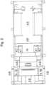
- Out of 2 is an arrangement of several of the in 1 assemblies shown within an airtight ducting in the housing of the air conditioner.
- This airtight ducting is stylized with a somewhat more strongly drawn and broken line contour.
- the mixed air flaps 2 for outside air / circulating air, air filter 3, supply air flaps 7, supply air fan 4, evaporator 5 and heating coil 6 of unit section B are for air treatment and their interfaces to outside air intake a and/or to circulating air intake b and to supply air outlet e1 and/or e2 arranged within the airtight ducting in the housing of the air conditioner designed as a compact device.
- reference AB denotes the ducting exterior environment and IB denotes the ducting interior air treatment area, where AB is open to the environment and potential leaks are vented to the outside and IB is the safe interior area, in where no leaks are to be expected, since the evaporator is designed as a safe evaporator.
- Out of 3 is a modified embodiment of the 2 arrangement shown.
- the device section A for the exhaust air with the pressure wave valve 1 and its interfaces to the exhaust air intake d and the exhaust air opening c is also arranged within a pressure-tight ducting in the housing of the air conditioning system.
- the pressure-tight canal routing is stylized with a slightly more strongly drawn and broken line contour.
- the reference AB designates the external environment viewed from the ductwork and the reference character IB designates the inner air treatment area as viewed from the ductwork.
- Out of 4 is a modified embodiment of the 2 arrangement shown.
- the electrical switch box C is also arranged within an airtight ducting in the housing of the air conditioning system.
- the airtight ducting is stylized with a somewhat more strongly drawn and broken line contour.
- the reference AB designates the external environment as seen from the ductwork and the reference character IB the internal air treatment area as seen from the ductwork, with the area AB being open to the environment and potential leaks being vented to the outside and IB representing the safe inner area in which no leaks are to be expected because the evaporator is designed as a safe evaporator.
- Out of figure 5 is a to 4 Another modified design can be seen by here (similar to in 3 )
- the device section A for the exhaust air with the pressure wave valve 1 and its interfaces to the exhaust air intake d and the exhaust air opening c is also arranged within an airtight and pressure-tight ducting in the housing of the air conditioning system.
- the airtight and pressure-tight ducting is stylized with a somewhat more strongly drawn and broken line contour.
- the reference AB designates the external environment as seen from the ductwork and the reference character IB the internal air treatment area as seen from the ductwork, with the area AB being open to the environment and potential leaks being vented to the outside and IB representing the safe inner area in which no leaks are to be expected because the evaporator as safe evaporator is executed.
- IB the internal air treatment area as seen from the ductwork
- Interfaces f1 and f2 are provided for chambered refrigerant lines in sections BR and C and partitions g1 and g2 to the sealed evaporator. Furthermore, evaporator 5, compressor 9, condenser 10, suction pressure sensor 11, solenoid valve liquid line 12, solenoid valve suction line 13, optional solenoid valve bypass line 14, suction line 15, liquid line 16 and optional bypass line 17 are shown as essential components for each refrigeration circuit
- the straight tubes of the evaporator 5 delimited by g1 and g2 and located in the IB are the only components of the refrigeration circuit that are located in the area of the airtight or pressure-tight ducting and can be damaged in the event of an accident or a significant rapid pressure drop (large refrigerant leakage outside or inside ) to be locked. This further minimizes the risk.
- the shut-off is implemented by closing the liquid line solenoid valve 12 and the solenoid valves 13 and 14 in the suction line 15 and the bypass line 17. In addition to this and before the refrigeration circuit is shut down, this shut-off area can also be emptied using the "pump out" function.
- the "pump out” takes place by closing the liquid line 12 solenoid valve and the bypass line 14 solenoid valve while the compressor 9 is running.
- This relates in detail to the liquid line 16 after the solenoid valve liquid line 12 through the areas f1 and f2, further via the pipeline package of the evaporator (BP) back via the suction line 15 and bypass line 17 through the areas f1 and f2.
- BP evaporator
- the compressor 9 is switched off and the solenoid valve 13 of the suction line 15 is closed.
- the position of the solenoid valves 12, 13 and 14 is only an example and can also be close to the evaporator 5, for example.
- the evacuation section can also be monitored by a person in the evacuation area located suction pressure sensor 11 and the repetition of the "pump out" function when a predetermined pressure is reached in the evacuation section.
- the increase in pressure is linked to the presence of refrigerant in the evacuated area.
- the evacuation status of the lockable area is additionally monitored.
Landscapes
- Engineering & Computer Science (AREA)
- Mechanical Engineering (AREA)
- Air-Conditioning For Vehicles (AREA)
- Other Air-Conditioning Systems (AREA)
Description
- Der hierin beschriebene Gegenstand betrifft eine Klimaanlage für ein Schienenfahrzeug, wobei die Klimaanlage für brennbare Kältemittel geeignet und als ein kompaktes Gerät für eine Montage auf einem Fahrzeugdach ausgestaltet ist und mindestens Gerätesektionen für eine Luftbehandlung und eine Verdichter-Verflüssiger-Einheit und optional Gerätesektionen für Fortluft, einen elektrischen Schaltkasten und/oder Schalldämpfer aufweist.
- Für Klimaanlagen in Fahrzeugen sind verschiedene Kältemittel bekannt, wobei insbesondere für die synthetischen Kältemittel die Verwendung unter ökologischen Aspekten problematisch ist. So wurde für Kraftfahrzeuge und auch für Schienenfahrzeuge das Kältemittel R134a sehr umfangreich eingesetzt. Allerdings wirkt dieses Kältemittel bei einem Austritt in die Atmosphäre als Treibhausgas. Deshalb wurde der Einsatz von Kältemittel R134a für PKW-Neufahrzeuge in der Europäischen Union zum 01-January-2017 beendet.
- Als Alternative für R134a wird nunmehr überwiegend das Kältemittel R1234yf verwendet, das einen wesentlich geringeren Treibhauseffekt besitzt, allerdings brennbar ist und als A2L- Kältemittel klassifiziert ist. Doch auch der Einsatz dieses Kältemittels wird inzwischen von Fachleuten kritisiert. So entsteht bei der Freisetzung in Verbindung mit Temperaturen 〉 250°C hoch giftige Flusssäure (HF) und in der Atmosphäre als Abbauprodukt persistente Trifluoressigsäure (TFA), die sich insbesondere im Wasser anreichert. Aufgrund der damit verbundenen Risiken wird grundsätzlich auch ein Verzicht auf HFO- Kältemittel wie R1234yf angestrebt.
- Eine Alternative dazu ist die Verwendung von Kohlenstoffdioxid (R744) als ein natürliches Kältemittel. Allerdings ergibt die Anwendung von R744 aufgrund der hohen Systemdrücke im Vergleich zu anderen Kältemitteln eine relativ aufwändige Gerätetechnik. Auch ist bei hohen Umgebungstemperaturen eine signifikante Verschlechterung der Leistungszahl (COP) zu verzeichnen und daher ein deutlicher Anstieg des Energiebedarfs für die Klimatisierung. Außerdem kommt es bei steigenden Umgebungstemperaturen zu einer starken Reduktion der Kälteleistung, dem durch eine entsprechend größere Dimensionierung der Komponenten begegnet werden kann.
- Somit ist offenkundig, dass die bisher eingesetzten Kältemittel letztlich einen Kompromiss zwischen unterschiedlichen funktionellen, umweltrelevanten und sicherheitstechnischen Anforderungen darstellen. Es besteht ein Bedarf an der Nutzung von Kältemitteln für Fahrzeugklimaanlagen, insbesondere auch für Schienenfahrzeuge, die ökologisch unkritisch beim Austritt an die Atmosphäre sind, eine hohe Energieeffizienz über den gesamten Arbeitsbereich aufweisen und den Wissens- und Erfahrungsstand der bisher verwendeten Kaltdampftechnologie weiternutzen können. Dabei sind diese Anlagen bei Schienenfahrzeugen überwiegend als kompakte Anlagen für das Fahrzeugdach konstruiert. Derartige Klimakompaktgeräte weisen unabhängig von ihrer jeweils konkreten Konstruktion typischerweise die Gerätesektionen Luftbehandlung und Verdichter-Verflüssiger-Einheit auf, und können optional die Gerätesektionen Fortluft, elektrischer Schaltkasten und/oder Schalldämpfer beinhalten.
- Als Lösung der oben beschriebenen Anforderungen sind brennbare Kohlenwasserstoffe wie z.B. Propan (R290), Propylen (R1270) oder Isobutan (R600a) als alternative Kältemittel interessant. Diese Kältemittel sind bei direktverdampfenden Anlagen mit begrenzten Füllmengen (〈150g bzw. 〈500g) vor allem im stationären Bereich weit verbreitetet. Bei der Notwendigkeit größerer Füllmengen zur Erzeugung größerer Kälteleistungen werden aufgrund ihrer Brennbarkeit vorzugsweise indirekte Systeme ausgeführt.
- Für eine Klimatisierung von Schienenfahrzeugen werden brennbare Kältemittel aufgrund der damit verbundenen Explosions- und Brandgefahr bisher kaum eingesetzt - weder als direkt noch als indirekt verdampfendes System. Bei einem indirekt verdampfenden System wird das o.g. Risiko reduziert, indem die Klimaanlage mit Sekundärkreislaufsystemen ausgeführt wird. Dabei wird in einem Primärkreislauf, der außerhalb des Fahrzeuges angeordnet ist und damit keine direkte Verbindung zum Fahrzeuginnenraum aufweist, die benötigte Kälte- (bzw. Heiz-) Leistung unter Verwendung brennbarer Kältemittel in üblichen Kompressionskältekreisläufen bereitgestellt. Diese Kälteleistung wird durch Wärmeübertrager (vorzugsweise Platten-Wärmeübertrager) auf einen Sekundärkreislauf übertragen, der zum Beispiel als Solekreislauf mit Wasser-Glykol-Gemischen ausgeführt ist.
- Eine diesbezügliche technische Lösung ist aus
WO 2018 / 137 908 A1 bekannt. Demzufolge weist ein Schienenfahrzeug einen primären Kältemittelkreislauf auf, der außerhalb vom Fahrzeug angeordnet und vom Fahrgastraum vollständig baulich getrennt ist. Ein sekundärer Kälteträgerkreislauf ist zumindest teilweise innerhalb des Schienenfahrzeuges angeordnet. Der Wärmeaustausch zwischen dem primären Kältemittelkreislauf und dem sekundären Kälteträgerkreislauf erfolgt durch einen Zwischenwärmetauscher, der unterflur im Außenbereich angeordnet ist. Dadurch wird der primäre Kältemittelkreislauf vollständig außerhalb vom Innenraum des Schienenfahrzeuges geführt. Durch diese Ausgestaltung sind die Sicherheitsbetrachtungen beim Einsatz brennbarer Stoffe im Wesentlichen für den Außenbereich durchzuführen, der Innenbereich kann als gleich sicher wie bei konventionellen Systemen angesetzt werden. Damit können auch solche Kältemittel verwendet werden, die aus sicherheitsrelevanten Aspekten bisher kaum zur Klimatisierung von Fahrgasträumen eingesetzt werden. Deshalb wird inWO 2018 / 137 908 A1 eine Verwendung brennbarer Kältemittel wie Propan vorgeschlagen, das unter funktionellen Aspekten gut als Kältemittel geeignet ist, wegen der oben erläuterten Probleme der Brand- und Explosionsgefahr bisher allerdings kaum verwendet wird. - Unter Beachtung des Standes der Technik gemäß
WO 2018 / 137 908 A1 und ähnlicher Lösungsvorschläge ist zu erwarten, dass sich die Akzeptanz für eine Verwendung von brennbaren Kältemitteln in Klimaanlagen für Schienenfahrzeuge mittelfristig stark erhöhen wird. Dabei ist jedoch zu beachten, dass durch den indirekten Kreislauf energetische Nachteile aufgrund der thermischen Verluste im Zwischenwärmeübertrager und ein Mehrgewicht sowie die Notwendigkeit für zusätzlichen Bauraum bestehen bleiben. Für die umfassende Nutzung brennbarer Kältemittel wird daher ein direktverdampfendes System angestrebt, das diese Nachteile vermeidet. Um den Brand- und Explosionsschutz auch bei möglichen Betriebsstörungen mit hoher Sicherheit gewährleisten zu können, sind daher weitere bauliche Maßnahmen an den Klimaanlagen von Schienenfahrzeugen ggf. erforderlich, die zu spezifischen Ausgestaltungen an verschiedenen Baugruppen führen. - Ein diesbezüglicher Lösungsansatz ist aus
DE 195 22 099 A1 bekannt, die eine Anordnung von Ventilatoren und anderen Bauteilen in druckdichten Kammern beschreibt. Weiterhin wird inDE 93 19 874 U1 vorgeschlagen, dass mehrere Baugruppen im Kältekreislauf einer Klimaanlage in einer druckdichten Struktur vollhermetisch abgeschottet werden, um unkontrollierte Austritte von Kältemittel zu vermeiden. Dieser Ansatz ist für den Fachmann grundsätzlich interessant. Allerdings vermitteln beide Druckschriften keine Anregung, wie die abstrakte Idee konkret umgesetzt werden kann. Außerdem sind sie in der beschriebenen Form nicht für brennbare Kältemittel geeignet. - Aufgabe des erfindungsgemäßen Gegenstands ist es, ein direktverdampfendes System zu realisieren, bei dem die zu klimatisierende Luft für den Passagierbereich derart innerhalb der Klimaanlage abgeschottet wird, dass bei Leckagen an kältemittelführenden Baugruppen der Eintrag von brennbaren Kältemittel in den Innenraum des Fahrzeuges ausgeschlossen ist.
- Diese Aufgabe wird gelöst, indem die kältemittelführenden Baugruppen und Bauteile außerhalb von den Bereichen der Komfortluftführung in einem separaten Gehäuse sowie offen zur Umgebung angeordnet sind. Demzufolge sind die Komponenten des Luftbehandlers, wie z.B. Mischluftklappen für Außenluft / Umluft, Luftfilter, Klappen, Zuluftventilator, Verdampfer und Heizregister sowie deren Schnittstellen zur Außenluftansaugung und/oder zur Umluftansaugung und zur Zuluftausblasung innerhalb einer luftabgedichteten und/oder druckdicht ausgeführten Kanalführung im Gehäuse des kompakten Gerätes bzw. ausgestalteten Klimaanlage angeordnet. Alle Komponenten außerhalb der Kanalführung sind offen zur Umgebung ausgeführt, so dass eventuell auftretende Leckagen nach außen abgelüftet bzw. abgeleitet werden.
- Somit ist die Komfortluftführung, d.h., die den Passagieren im Fahrzeug zuzuführende Luft, im Gerät separiert und gegenüber dem Kältekreislauf hermetisiert, wobei die kältemitteltechnischen Teile als ein üblicher und bekannter hermetischer Kältekreislauf ausgeführt sind. Eine Neuheit gegenüber dem bekannten Stand der Technik besteht folglich darin, dass alle kältemittelführenden Teile außerhalb der Komfortluftführung liegen und in einem Gehäuse angeordnet sind, so dass sie gegen Beschädigungen oder versehentliche Zugriffe geschützt sind. Dabei sind die kältemittelführenden Teile zur Umgebung offen angeordnet, um durch eine passive Belüftung eventuell auftretende Leckagen nach außen abzuführen und zündfähige Konzentrationen über einen längeren Zeitraum zu verhindern. Sofern keine potentiellen Zündquellen vorhanden sind, können die kältemittelführenden Teile auch in einem separaten geschlossenen, nicht luftdichten Bereich angeordnet werden. Weiterhin erfolgt zur Verhinderung des Eindringens von Kältemittel in den Bereich der Komfortluftführung eine entsprechende Abdichtung (technisch dicht) zwischen den beiden Bereichen von Komfortluftführung und Gehäuse mit kältemittelführenden Komponenten. Weitere vorteilhafte Ausgestaltungen sind Gegenstand von Unteransprüchen, deren technische Merkmale in einem Ausführungsbeispiel beschrieben werden.
- Mit der technischen Lösung gemäß des erfindungsgemäßen Gegenstands werden die für die Luftbehandlung funktionswesentlichen Baugruppen einer Klimaanlage für ein Schienenfahrzeug derart abgeschottet, dass durch eine luft- und/oder druckdichte Kanalausbildung ein Kontakt dieser Baugruppen mit brennbaren Kältemitteln infolge Leckagen verhindert wird. Dadurch wird die Akzeptanz für eine Verwendung von brennbaren Kältemitteln in Klimaanlagen für Schienenfahrzeuge erhöht. Denn nunmehr ist es möglich, den Brand- und Explosionsschutz auch bei einem unkontrollierten Austritt des brennbaren Kältemittels im Außenbereich für den innenliegenden Bereich zu gewährleisten.
- Nachfolgend wird ein Ausführungsbeispiel des erfindungsgemäßen Gegenstands unter Bezugnahme auf die Zeichnungen näher erläutert. Es zeigen in jeweils stilisierter Darstellung:
-
Fig. 1 den grundsätzlichen Aufbau einer Klimaanlage für ein Schienenfahrzeug, die für brennbare Kältemittel geeignet ist und als ein kompaktes Gerät für eine Montage auf dem Fahrzeugdach ausgestaltet ist, hier ohne Darstellung des Gehäuses der Klimaanlage; -
Fig. 2 eine erste Ausführung zur Anordnung von Baugruppen der Klimaanlage innerhalb einer luftdichten Kanalführung; -
Fig. 3 eine zweite Ausführung zur Anordnung von Baugruppen der Klimaanlage innerhalb einer druckdichten Kanalführung; -
Fig. 4 eine dritte Ausführung zur Anordnung von Baugruppen der Klimaanlage innerhalb einer luftdichten Kanalführung; -
Fig. 5 eine vierte Ausführung zur Anordnung von Baugruppen der Klimaanlage innerhalb einer druckdichten Kanalführung; und -
Fig. 6 ein Beispiel für eine konkrete Ausführung der kältemittelführenden Leitungsabschnitte des Verdampfers bei luftdichten oder druckdichten Kanalausbildungen. - Aus
Fig. 1 ist der grundsätzliche Aufbau einer Klimaanlage für ein (nicht gezeigtes) Schienenfahrzeug ersichtlich, die für brennbare Kältemittel der Kategorie A2, A2L und A3 geeignet ist und als ein kompaktes Gerät für eine Montage auf dem Dach des Schienenfahrzeuges ausgestaltet ist. Hierbei sind lediglich die wesentlichen Komponenten der Luftbehandlung ohne das Gehäuse der Klimaanlage dargestellt. Demzufolge weist die Klimaanlage eine optionale Gerätesektion A für Fortluft, eine Gerätesektion B für die Luftbehandlung, einen optionalen elektrischen Schaltkasten C und eine Verdichter- Verflüssiger-Einheit D auf. Die Sektionen B und A können als wesentliche Bauteile Druckwellenventile 1, Mischluftklappen 2 für Außenluft / Umluft, Luftfilter 3, Zuluftventilator 4, Verdampfer 5, Heizregister 6, Zuluftklappen 7 und Fortlüfter 8 wie dargestellt umfassen. Weiterhin sind Schnittstellen zur Außenluftansaugung a, zur Umluftansaugung b, zur Fortluftöffnung c, zur Fortluftansaugung d, zur Zuluftausblasung e1 und zur Zuluftausblasung e 2 vorgesehen. - Aus
Fig. 2 ist eine Anordnung von mehreren der inFig. 1 dargestellten Baugruppen innerhalb einer luftdichten Kanalführung im Gehäuse der Klimaanlage ersichtlich. Diese luftdichte Kanalführung ist mit einer etwas stärker gezeichneten und unterbrochenen Linienkontur stilisiert. Demzufolge sind die Mischluftklappen 2 für Außenluft / Umluft, Luftfilter 3, Zuluftklappen 7, Zuluftventilator 4, Verdampfer 5 und Heizregister 6 der Gerätesektion B für die Luftbehandlung sowie deren Schnittstellen zur Außenluftansaugung a und/oder zur Umluftansaugung b und zur Zuluftausblasung e1 und/oder e2 innerhalb der luftdichten Kanalführung im Gehäuse der als ein kompaktes Gerät ausgestalteten Klimaanlage angeordnet. Diesbezüglich bezeichnet das Bezugszeichen AB die zur Kanalführung gesehen äußere Umgebung und das Bezugszeichen IB den zur Kanalführung gesehen inneren Luftbehandlungsbereich, wobei der Bereich AB offen zur Umgebung ist und potentielle Leckagen nach außen abgelüftet bzw. abgeleitet werden und IB den sicheren inneren Bereich darstellt, in dem keine Leckagen zu erwarten sind, da der Verdampfer als sicherer Verdampfer ausgeführt ist. - Aus
Fig. 3 ist eine modifizierte Ausgestaltung der inFig. 2 gezeigten Anordnung ersichtlich. Bei dieser Variante ist auch die Gerätesektion A für die Fortluft mit dem Druckwellenventil 1 und deren Schnittstellen zur Fortluftansaugung d und zur Fortluftöffnung c innerhalb einer druckdichten Kanalführung im Gehäuse der Klimaanlage angeordnet. Auch hier ist die druckdichte Kanalführung mit einer etwas stärker gezeichneten und unterbrochenen Linienkontur stilisiert. Ebenso bezeichnet das Bezugszeichen AB die zur Kanalführung gesehen äußere Umgebung und das Bezugszeichen IB den zur Kanalführung gesehen inneren Luftbehandlungsbereich. - Aus
Fig. 4 ist eine modifizierte Ausgestaltung der inFig. 2 gezeigten Anordnung ersichtlich. Bei dieser Variante ist auch der elektrische Schaltkasten C innerhalb einer luftdichten Kanalführung im Gehäuse der Klimaanlage angeordnet. Auch hier ist die luftdichte Kanalführung mit einer etwas stärker gezeichneten und unterbrochenen Linienkontur stilisiert. Ebenso bezeichnet das Bezugszeichen AB die zur Kanalführung gesehen äußere Umgebung und das Bezugszeichen IB den zur Kanalführung gesehen inneren Luftbehandlungsbereich, wobei der Bereich AB offen zur Umgebung ist und potentielle Leckagen nach außen abgelüftet bzw. abgeleitet werden und IB den sicheren inneren Bereich darstellt, in dem keine Leckagen zu erwarten sind, da der Verdampfer als sicherer Verdampfer ausgeführt ist. - Aus
Fig. 5 ist eine zurFig. 4 nochmals modifizierte Ausgestaltung ersichtlich, indem hier (ähnlich wie inFig. 3 ) auch die Gerätesektion A für die Fortluft mit dem Druckwellenventil 1 und deren Schnittstellen zur Fortluftansaugung d und zur Fortluftöffnung c innerhalb einer luft- und druckdichten Kanalführung im Gehäuse der Klimaanlage angeordnet ist. Auch hier ist die luft- und druckdichte Kanalführung mit einer etwas stärker gezeichneten und unterbrochenen Linienkontur stilisiert. Ebenso bezeichnet das Bezugszeichen AB die zur Kanalführung gesehen äußere Umgebung und das Bezugszeichen IB den zur Kanalführung gesehen inneren Luftbehandlungsbereich, wobei der Bereich AB offen zur Umgebung ist und potentielle Leckagen nach außen abgelüftet bzw. abgeleitet werden und IB den sicheren inneren Bereich darstellt, in dem keine Leckagen zu erwarten sind, da der Verdampfer als sicherer Verdampfer ausgeführt ist. AusFig. 6 ist ein Beispiel für eine konkrete Anordnung und Ausführung der kältemittelführenden Leitungsabschnitte des Verdampfers 5 ersichtlich. In dieserFig. 6 sind zwei Kältekreislaufsektionen BP (Rohrbündelpaket Innenseite Verdampfer) und BR (Bereich der Kältekreislaufleitungen in der Luftbehandlungssektion) sowie der elektrische Schaltkasten C und die Verdichter-Verflüssiger-Einheit D dargestellt. Es sind Schnittstellen f1 und f2 vorgesehen für gekammerte Kältemittelleitungen in den Sektionen BR und C und Trennwände g1 und g2 zum dichten Verdampfer. Weiterhin sind als wesentliche Bauteile je Kältekreislauf Verdampfer5, Verdichter 9, Verflüssiger 10, Saugdrucksensor 11, Magnetventil Flüssigkeitsleitung 12, Magnetventil Saugleitung 13, optionales Magnetventil Bypassleitung 14, Saugleitung 15, Flüssigkeitsleitung 16 und optionale Bypassleitung 17 dargestellt - Die begrenzt durch g1 und g2 und im IB befindlichen geraden Rohre des Verdampfers 5 sind die einzigen Komponenten des Kältekreislaufes, die sich im Bereich der luft- oder druckdichten Kanalführung befinden und können bei einer Havarie oder bei einem signifikanten schnellen Druckabfall (große Kältemittelleckage außen oder innen) abgesperrt werden. Damit wird eine weitere Risikominimierung erreicht. Die Absperrung wird realisiert durch Schließen des Magnetventils Flüssigkeitsleitung 12 und der Magnetventile 13 und 14 in der Saugleitung 15 und der Bypassleitung 17. Erweiternd dazu und vor Stillsetzung des Kältekreislaufes kann zusätzlich dieser absperrbare Bereich durch die "Pump out"-Funktion entleert werden. Das "Pump out" erfolgt durch Schließen des Magnetventils Flüssigkeitsleitung 12 und des Magnetventils Bypassleitung 14 bei laufendem Verdichter 9. Damit wird die gesamte Rohrführung vom Magnetventil Flüssigkeitsleitung 12 bis zur Saugseite des Verdichters 9 abgesaugt. Dies betrifft im Einzelnen die Flüssigkeitsleitung 16 nach dem Magnetventil Flüssigkeitsleitung 12 durch die Bereiche f1 und f2, weiter über das Rohrleitungspaket des Verdampfers (BP) zurück über die Saugleitung 15 und Bypassleitung 17 durch die Bereiche f1 und f2. Bei Erreichen eines definierten Saugdruckes wird der Verdichter 9 abgeschaltet und das Magnetventil 13 der Saugleitung 15 geschlossen. Die Lage der Magnetventile 12, 13 und 14 ist lediglich beispielhaft und kann zum Beispiel auch dicht am Verdampfer 5 erfolgen. Erweiternd dazu und nach Stillsetzung und Evakuierung des Kältekreislaufes kann zusätzlich eine Überwachung des Evakuierungsabschnittes durch einen im Evakuierungsbereich befindlichen Saugdrucksensor 11 und der Wiederholung der "Pump out"-Funktion bei Erreichung eines vorgegebenen Druckes im Evakuierungsabschnitt erfolgen. Dabei wird der Druckanstieg mit dem Vorhandensein von Kältemittel im evakuierten Bereich verknüpft. Dadurch wird der Evakuierungszustand des absperrbaren Bereiches zusätzlich überwacht.
Claims (4)
- Klimaanlage für ein Schienenfahrzeug, wobei die Klimaanlage für brennbare Kältemittel der Kategorien A2, A2L, und A3 geeignet und als ein kompaktes Gerät für eine Montage auf einem Fahrzeugdach ausgestaltet ist und mindestens Gerätesektionen für eine Luftbehandlungssektion (B), eine Verdichter-Verflüssiger-Einheit (D) und eine Fortluftsektion (A) aufweist, wobei die Fortluftsektion (A) mindestens erste Schnittstellen zur Fortluftansaugung und zur Fortluftöffnung aufweist und wobei die Luftbehandlungssektion (B) mindestens zweite Schnittstellen zur Außenluftansaugung und zur Umluftansaugung sowie zur Zuluftausblasung, Luftfilter (3), einen Verdampfer (5) und Zuluftventilator (4) und eine Mischluftklappe (2) für Außenluft oder Umluft, Zuluftklappen (7), und ein Heizregister (6) aufweist,
dadurch gekennzeichnet, dass
kältemittelführende Baugruppen und Bauteile der Klimaanlage außerhalb der Bereiche der Komfortluftführung liegen und in einem separaten Gehäuse sowie offen zur Umgebung angeordnet sind, wobei zumindest die Mischluftklappe (2) für Außenluft oder Umluft, der Luftfilter (3), die Zuluftklappen (7), der Zuluftventilator (4), der Verdampfer (5), und das Heizregister (6) der Luftbehandlungssektion (B) sowie deren zweite Schnittstellen zur Außenluftansaugung (a) oder zur Umluftansaugung (b) und der Zuluftausblasung (e1 und/oder e2) innerhalb einer luft- oder druckdichten Kanalführung im Gehäuse der als ein kompaktes Gerät ausgestalteten Klimaanlage angeordnet sind. - Klimaanlage nach Anspruch 1, dadurch gekennzeichnet, dass ein Druckwellenventil (1) der Fortluftsektion (A) und die ersten Schnittstellen zur Fortluftansaugung (d) und zur Fortluftöffnung (c) innerhalb der druckdichten Kanalführung im Gehäuse der Klimaanlage angeordnet sind.
- Klimaanlage nach einem der Ansprüche 1 oder 2, dadurch gekennzeichnet, dass ein elektrischer Schaltkasten (C) innerhalb der luft- oder druckdichten Kanalführung im Gehäuse der Klimaanlage angeordnet ist.
- Klimaanlage nach mindestens einem der Ansprüche 1 bis 3, dadurch gekennzeichnet, dass kältemittelführende Leitungsabschnitte des Verdampfers (5), als einzige Komponente eines Kältemittelkreislaufs in einem Bereich der luft- oder druckdichten Kanalführung angeordnet und absperrbar sind, erweiternd evakuierbar, und erweiternd überwacht evakuiert ausgestaltet sind.
Applications Claiming Priority (2)
| Application Number | Priority Date | Filing Date | Title |
|---|---|---|---|
| DE202019104698 | 2019-08-27 | ||
| PCT/DE2020/100718 WO2021037309A1 (de) | 2019-08-27 | 2020-08-18 | Klimaanlage für ein schienenfahrzeug (mit luft- oder druckdichter kanalausbildung in der luftbehandlungssektion) |
Publications (2)
| Publication Number | Publication Date |
|---|---|
| EP4017777A1 EP4017777A1 (de) | 2022-06-29 |
| EP4017777B1 true EP4017777B1 (de) | 2023-08-02 |
Family
ID=72266091
Family Applications (1)
| Application Number | Title | Priority Date | Filing Date |
|---|---|---|---|
| EP20763982.4A Active EP4017777B1 (de) | 2019-08-27 | 2020-08-18 | Klimaanlage für ein schienenfahrzeug (mit luft- oder druckdichter kanalausbildung in der luftbehandlungssektion) |
Country Status (10)
| Country | Link |
|---|---|
| US (1) | US12116022B2 (de) |
| EP (1) | EP4017777B1 (de) |
| JP (1) | JP7289928B2 (de) |
| KR (1) | KR102813617B1 (de) |
| CN (2) | CN120573142A (de) |
| AU (1) | AU2020339069B2 (de) |
| CA (1) | CA3136515C (de) |
| DE (2) | DE202020104571U1 (de) |
| IL (1) | IL287235B2 (de) |
| WO (1) | WO2021037309A1 (de) |
Families Citing this family (3)
| Publication number | Priority date | Publication date | Assignee | Title |
|---|---|---|---|---|
| EP3999392B1 (de) * | 2019-08-27 | 2023-08-09 | Faiveley Transport Leipzig GmbH & Co. KG | Klimaanlage für ein fahrzeug (überdruck im e-kasten) |
| DE202023103254U1 (de) | 2023-06-13 | 2024-06-07 | Faiveley Transport Leipzig Gmbh | Vorrichtung zur Detektion von austretendem Kältemittel aus einem Klimakompaktgerät für ein Schienenfahrzeug |
| DE102024204164A1 (de) | 2024-05-06 | 2025-11-20 | Siemens Mobility GmbH | Kälteanlage |
Family Cites Families (20)
| Publication number | Priority date | Publication date | Assignee | Title |
|---|---|---|---|---|
| AT397998B (de) * | 1992-07-09 | 1994-08-25 | Friedmann Kg Alex | Kältemaschine |
| DE4304194C2 (de) * | 1993-02-12 | 1995-10-12 | Hagenuk Fahrzeugklima Gmbh | Verfahren und Vorrichtung zum Regulieren von Frischluftmengen in Hochgeschwindigkeitszügen |
| DE9319874U1 (de) | 1993-12-24 | 1994-03-31 | Hagenuk Fahrzeugklima GmbH, 04435 Schkeuditz | Heizungs- und Kühlanlage |
| DE19522099A1 (de) | 1995-06-19 | 1997-01-02 | Ernst Dipl Ing Lex | Belüftungsvorrichtung mit Druckschutz-Ventilator |
| US5605055A (en) * | 1995-10-20 | 1997-02-25 | Carrier Corporation | Roof mounted air conditioner |
| FR2787407B1 (fr) * | 1998-12-18 | 2001-02-09 | Regie Autonome Des Transp S Pa | Procede de conditionnement et de diffusion d'air dans un vehicule, et vehicule pour la mise en oeuvre de ce procede |
| DE10046935B4 (de) * | 2000-09-21 | 2004-04-15 | Thermo King Deutschland Gmbh | Heiz- und gegebenenfalls Klimagerät für Nutzfahrzeuge, z. B. Omnibusse |
| US20080245503A1 (en) * | 2007-04-09 | 2008-10-09 | Wilson Michael J | Heat exchange system for vehicles and method of operating the same |
| DE102009028522B4 (de) * | 2009-08-13 | 2017-05-11 | Hanon Systems | Kompakte Klimaanlage für ein Kraftfahrzeug |
| JP2012136159A (ja) * | 2010-12-27 | 2012-07-19 | Mitsubishi Electric Corp | 鉄道車両用空調装置及び鉄道車両 |
| WO2013037335A1 (de) * | 2011-09-16 | 2013-03-21 | Faiveley Transport Leipzig Gmbh & Co. Kg | Klimaanlage für schienenfahrzeuge |
| DE102013011600B3 (de) * | 2013-07-11 | 2014-10-09 | Konvekta Ag | Fahrzeugaufdachklimaanlage mit Redundanzeinrichtung |
| DE102014112545B4 (de) * | 2014-09-01 | 2022-06-02 | Denso Automotive Deutschland Gmbh | Kompaktaggregat für ein Kraftfahrzeug und Verfahren zur Notfallbehandlung einer Kraftfahrzeugklimaanlage |
| DE202014104358U1 (de) * | 2014-09-15 | 2014-12-12 | Faiveley Transport Leipzig Gmbh & Co. Kg | Vorrichtung für eine kombinierte Druckschutz- und Luftmengenregelung im Innenraum von Schienenfahrzeugen |
| DE102015203668A1 (de) * | 2015-03-02 | 2016-09-08 | Siemens Aktiengesellschaft | Schienenfahrzeug mit Traktionskühlanlage |
| CN205706682U (zh) * | 2016-03-31 | 2016-11-23 | 山东朗进科技股份有限公司 | 轨道车辆空调系统 |
| DE102017201186A1 (de) | 2017-01-25 | 2018-07-26 | Siemens Aktiengesellschaft | Fahrzeug mit einer zweistufigen Kälteanlage |
| WO2019127206A1 (zh) * | 2017-12-26 | 2019-07-04 | 中车长春轨道客车股份有限公司 | 轨道列车及其单元空调机组 |
| CN109367555B (zh) * | 2018-11-22 | 2024-07-16 | 株洲联诚集团控股股份有限公司 | 一种分体式动车组用食物保鲜用制冷装置 |
| CN110104008A (zh) * | 2019-04-23 | 2019-08-09 | 广州鼎汉轨道交通车辆装备有限公司 | 一种轨道车辆的空调机组控制方法及系统 |
-
2020
- 2020-08-07 DE DE202020104571.7U patent/DE202020104571U1/de active Active
- 2020-08-18 EP EP20763982.4A patent/EP4017777B1/de active Active
- 2020-08-18 CN CN202510604835.6A patent/CN120573142A/zh active Pending
- 2020-08-18 JP JP2021559292A patent/JP7289928B2/ja active Active
- 2020-08-18 DE DE112020004126.3T patent/DE112020004126A5/de active Pending
- 2020-08-18 IL IL287235A patent/IL287235B2/en unknown
- 2020-08-18 KR KR1020217035179A patent/KR102813617B1/ko active Active
- 2020-08-18 US US17/599,074 patent/US12116022B2/en active Active
- 2020-08-18 AU AU2020339069A patent/AU2020339069B2/en active Active
- 2020-08-18 CA CA3136515A patent/CA3136515C/en active Active
- 2020-08-18 CN CN202080032651.2A patent/CN113767045B/zh active Active
- 2020-08-18 WO PCT/DE2020/100718 patent/WO2021037309A1/de not_active Ceased
Also Published As
| Publication number | Publication date |
|---|---|
| JP7289928B2 (ja) | 2023-06-12 |
| CN113767045B (zh) | 2025-05-27 |
| AU2020339069B2 (en) | 2023-05-25 |
| DE202020104571U1 (de) | 2020-10-27 |
| IL287235A (en) | 2021-12-01 |
| EP4017777A1 (de) | 2022-06-29 |
| CN113767045A (zh) | 2021-12-07 |
| CA3136515C (en) | 2023-10-31 |
| KR102813617B1 (ko) | 2025-05-29 |
| CA3136515A1 (en) | 2021-03-04 |
| CN120573142A (zh) | 2025-09-02 |
| BR112021020324A2 (pt) | 2022-03-29 |
| US12116022B2 (en) | 2024-10-15 |
| AU2020339069A1 (en) | 2021-11-04 |
| IL287235B2 (en) | 2026-04-01 |
| DE112020004126A5 (de) | 2022-07-07 |
| WO2021037309A1 (de) | 2021-03-04 |
| IL287235B1 (en) | 2025-12-01 |
| US20220177013A1 (en) | 2022-06-09 |
| KR20210143305A (ko) | 2021-11-26 |
| JP2022540537A (ja) | 2022-09-16 |
Similar Documents
| Publication | Publication Date | Title |
|---|---|---|
| DE102012108731B4 (de) | Klimaanlage für ein Kraftfahrzeug | |
| DE102019129304A1 (de) | Wärmepumpensystem für ein Fahrzeug | |
| DE102017103425A1 (de) | Verfahren und System zum Betreiben einer Wärmepumpe eines Fahrzeugs | |
| DE102018110007A1 (de) | Modulierendes fahrzeugheiz- und kühlsystem und steuerverfahren | |
| DE102019129442A1 (de) | Wärmepumpensystem für ein Fahrzeug | |
| EP3693683A1 (de) | Diffusionssperre mittels schutzschichten | |
| WO2021037309A1 (de) | Klimaanlage für ein schienenfahrzeug (mit luft- oder druckdichter kanalausbildung in der luftbehandlungssektion) | |
| DE102013210970B4 (de) | Klimasteuerungssysteme für Motorfahrzeuge und Verfahren zum Betreiben derselben | |
| DE102019203292B4 (de) | Verfahren zum Betreiben einer Kälteanlage für ein Fahrzeug mit einem eine Wärmepumpenfunktion aufweisenden Kältemittelkreislauf | |
| DE102017201186A1 (de) | Fahrzeug mit einer zweistufigen Kälteanlage | |
| DE112016001202T5 (de) | Klimaanlage für Fahrzeug | |
| DE102016122669B4 (de) | Klimaanlagensystem für ein Fahrzeug | |
| DE112013002754B4 (de) | Heizungs-, Lüftungs- und/oder Klimaanlage für ein Kraftfahrzeug und Verfahren zum Betrieb einer solchen Anlage | |
| EP4522481B1 (de) | Anordnung zur belüftung eines schienenfahrzeugraums | |
| DE102011053906A1 (de) | Luftentfeuchtungseinheit und -verfahren | |
| EP3999392B1 (de) | Klimaanlage für ein fahrzeug (überdruck im e-kasten) | |
| DE102013219146A1 (de) | Fahrzeug-wärmepumpensystem und -steuerverfahren | |
| DE102015118221A1 (de) | Kältemittelkreislauf für eine Fahrzeugklimaanlage mit Wärmepumpenfunktion | |
| DE102014108454B4 (de) | Kältemittelkreislauf mit einer Bypassleitung | |
| DE102017208296B4 (de) | Verfahren zur Begrenzung eines aus einem Kältemittelkreislauf einer Fahrzeugklimaanlage austretenden Kältemittels sowie Fahrzeugklimaanlage | |
| DE102015210068A1 (de) | Klimatisierungseinrichtung, insbesondere für ein Fahrzeug | |
| EP1715262A2 (de) | Überdrucksicherheitseinrichtung für einen Kältemittelkreislauf | |
| DE102015209536B4 (de) | Kälteanlage | |
| DE202023103254U1 (de) | Vorrichtung zur Detektion von austretendem Kältemittel aus einem Klimakompaktgerät für ein Schienenfahrzeug | |
| DE202019104700U1 (de) | Klimaanlage für ein Schienenfahrzeug (Druckentlastung im Kältekreis durch Abblasen von Kältemittel über Diffusor) |
Legal Events
| Date | Code | Title | Description |
|---|---|---|---|
| STAA | Information on the status of an ep patent application or granted ep patent |
Free format text: STATUS: UNKNOWN |
|
| STAA | Information on the status of an ep patent application or granted ep patent |
Free format text: STATUS: THE INTERNATIONAL PUBLICATION HAS BEEN MADE |
|
| PUAI | Public reference made under article 153(3) epc to a published international application that has entered the european phase |
Free format text: ORIGINAL CODE: 0009012 |
|
| STAA | Information on the status of an ep patent application or granted ep patent |
Free format text: STATUS: REQUEST FOR EXAMINATION WAS MADE |
|
| 17P | Request for examination filed |
Effective date: 20220322 |
|
| AK | Designated contracting states |
Kind code of ref document: A1 Designated state(s): AL AT BE BG CH CY CZ DE DK EE ES FI FR GB GR HR HU IE IS IT LI LT LU LV MC MK MT NL NO PL PT RO RS SE SI SK SM TR |
|
| DAV | Request for validation of the european patent (deleted) | ||
| DAX | Request for extension of the european patent (deleted) | ||
| GRAP | Despatch of communication of intention to grant a patent |
Free format text: ORIGINAL CODE: EPIDOSNIGR1 |
|
| STAA | Information on the status of an ep patent application or granted ep patent |
Free format text: STATUS: GRANT OF PATENT IS INTENDED |
|
| INTG | Intention to grant announced |
Effective date: 20230315 |
|
| GRAS | Grant fee paid |
Free format text: ORIGINAL CODE: EPIDOSNIGR3 |
|
| GRAA | (expected) grant |
Free format text: ORIGINAL CODE: 0009210 |
|
| STAA | Information on the status of an ep patent application or granted ep patent |
Free format text: STATUS: THE PATENT HAS BEEN GRANTED |
|
| AK | Designated contracting states |
Kind code of ref document: B1 Designated state(s): AL AT BE BG CH CY CZ DE DK EE ES FI FR GB GR HR HU IE IS IT LI LT LU LV MC MK MT NL NO PL PT RO RS SE SI SK SM TR |
|
| REG | Reference to a national code |
Ref country code: GB Ref legal event code: FG4D Free format text: NOT ENGLISH |
|
| REG | Reference to a national code |
Ref country code: CH Ref legal event code: EP |
|
| REG | Reference to a national code |
Ref country code: DE Ref legal event code: R096 Ref document number: 502020004539 Country of ref document: DE |
|
| REG | Reference to a national code |
Ref country code: IE Ref legal event code: FG4D Free format text: LANGUAGE OF EP DOCUMENT: GERMAN |
|
| P01 | Opt-out of the competence of the unified patent court (upc) registered |
Effective date: 20230727 |
|
| REG | Reference to a national code |
Ref country code: LT Ref legal event code: MG9D |
|
| REG | Reference to a national code |
Ref country code: NL Ref legal event code: MP Effective date: 20230802 |
|
| PG25 | Lapsed in a contracting state [announced via postgrant information from national office to epo] |
Ref country code: GR Free format text: LAPSE BECAUSE OF FAILURE TO SUBMIT A TRANSLATION OF THE DESCRIPTION OR TO PAY THE FEE WITHIN THE PRESCRIBED TIME-LIMIT Effective date: 20231103 |
|
| PG25 | Lapsed in a contracting state [announced via postgrant information from national office to epo] |
Ref country code: IS Free format text: LAPSE BECAUSE OF FAILURE TO SUBMIT A TRANSLATION OF THE DESCRIPTION OR TO PAY THE FEE WITHIN THE PRESCRIBED TIME-LIMIT Effective date: 20231202 |
|
| PG25 | Lapsed in a contracting state [announced via postgrant information from national office to epo] |
Ref country code: SE Free format text: LAPSE BECAUSE OF FAILURE TO SUBMIT A TRANSLATION OF THE DESCRIPTION OR TO PAY THE FEE WITHIN THE PRESCRIBED TIME-LIMIT Effective date: 20230802 Ref country code: RS Free format text: LAPSE BECAUSE OF FAILURE TO SUBMIT A TRANSLATION OF THE DESCRIPTION OR TO PAY THE FEE WITHIN THE PRESCRIBED TIME-LIMIT Effective date: 20230802 Ref country code: PT Free format text: LAPSE BECAUSE OF FAILURE TO SUBMIT A TRANSLATION OF THE DESCRIPTION OR TO PAY THE FEE WITHIN THE PRESCRIBED TIME-LIMIT Effective date: 20231204 Ref country code: NO Free format text: LAPSE BECAUSE OF FAILURE TO SUBMIT A TRANSLATION OF THE DESCRIPTION OR TO PAY THE FEE WITHIN THE PRESCRIBED TIME-LIMIT Effective date: 20231102 Ref country code: NL Free format text: LAPSE BECAUSE OF FAILURE TO SUBMIT A TRANSLATION OF THE DESCRIPTION OR TO PAY THE FEE WITHIN THE PRESCRIBED TIME-LIMIT Effective date: 20230802 Ref country code: LV Free format text: LAPSE BECAUSE OF FAILURE TO SUBMIT A TRANSLATION OF THE DESCRIPTION OR TO PAY THE FEE WITHIN THE PRESCRIBED TIME-LIMIT Effective date: 20230802 Ref country code: LT Free format text: LAPSE BECAUSE OF FAILURE TO SUBMIT A TRANSLATION OF THE DESCRIPTION OR TO PAY THE FEE WITHIN THE PRESCRIBED TIME-LIMIT Effective date: 20230802 Ref country code: IS Free format text: LAPSE BECAUSE OF FAILURE TO SUBMIT A TRANSLATION OF THE DESCRIPTION OR TO PAY THE FEE WITHIN THE PRESCRIBED TIME-LIMIT Effective date: 20231202 Ref country code: HR Free format text: LAPSE BECAUSE OF FAILURE TO SUBMIT A TRANSLATION OF THE DESCRIPTION OR TO PAY THE FEE WITHIN THE PRESCRIBED TIME-LIMIT Effective date: 20230802 Ref country code: GR Free format text: LAPSE BECAUSE OF FAILURE TO SUBMIT A TRANSLATION OF THE DESCRIPTION OR TO PAY THE FEE WITHIN THE PRESCRIBED TIME-LIMIT Effective date: 20231103 Ref country code: FI Free format text: LAPSE BECAUSE OF FAILURE TO SUBMIT A TRANSLATION OF THE DESCRIPTION OR TO PAY THE FEE WITHIN THE PRESCRIBED TIME-LIMIT Effective date: 20230802 |
|
| PG25 | Lapsed in a contracting state [announced via postgrant information from national office to epo] |
Ref country code: PL Free format text: LAPSE BECAUSE OF FAILURE TO SUBMIT A TRANSLATION OF THE DESCRIPTION OR TO PAY THE FEE WITHIN THE PRESCRIBED TIME-LIMIT Effective date: 20230802 |
|
| PG25 | Lapsed in a contracting state [announced via postgrant information from national office to epo] |
Ref country code: LU Free format text: LAPSE BECAUSE OF NON-PAYMENT OF DUE FEES Effective date: 20230818 |
|
| PG25 | Lapsed in a contracting state [announced via postgrant information from national office to epo] |
Ref country code: ES Free format text: LAPSE BECAUSE OF FAILURE TO SUBMIT A TRANSLATION OF THE DESCRIPTION OR TO PAY THE FEE WITHIN THE PRESCRIBED TIME-LIMIT Effective date: 20230802 |
|
| PG25 | Lapsed in a contracting state [announced via postgrant information from national office to epo] |
Ref country code: SM Free format text: LAPSE BECAUSE OF FAILURE TO SUBMIT A TRANSLATION OF THE DESCRIPTION OR TO PAY THE FEE WITHIN THE PRESCRIBED TIME-LIMIT Effective date: 20230802 Ref country code: RO Free format text: LAPSE BECAUSE OF FAILURE TO SUBMIT A TRANSLATION OF THE DESCRIPTION OR TO PAY THE FEE WITHIN THE PRESCRIBED TIME-LIMIT Effective date: 20230802 Ref country code: LU Free format text: LAPSE BECAUSE OF NON-PAYMENT OF DUE FEES Effective date: 20230818 Ref country code: ES Free format text: LAPSE BECAUSE OF FAILURE TO SUBMIT A TRANSLATION OF THE DESCRIPTION OR TO PAY THE FEE WITHIN THE PRESCRIBED TIME-LIMIT Effective date: 20230802 Ref country code: EE Free format text: LAPSE BECAUSE OF FAILURE TO SUBMIT A TRANSLATION OF THE DESCRIPTION OR TO PAY THE FEE WITHIN THE PRESCRIBED TIME-LIMIT Effective date: 20230802 Ref country code: DK Free format text: LAPSE BECAUSE OF FAILURE TO SUBMIT A TRANSLATION OF THE DESCRIPTION OR TO PAY THE FEE WITHIN THE PRESCRIBED TIME-LIMIT Effective date: 20230802 Ref country code: SK Free format text: LAPSE BECAUSE OF FAILURE TO SUBMIT A TRANSLATION OF THE DESCRIPTION OR TO PAY THE FEE WITHIN THE PRESCRIBED TIME-LIMIT Effective date: 20230802 |
|
| REG | Reference to a national code |
Ref country code: DE Ref legal event code: R097 Ref document number: 502020004539 Country of ref document: DE |
|
| PG25 | Lapsed in a contracting state [announced via postgrant information from national office to epo] |
Ref country code: IT Free format text: LAPSE BECAUSE OF FAILURE TO SUBMIT A TRANSLATION OF THE DESCRIPTION OR TO PAY THE FEE WITHIN THE PRESCRIBED TIME-LIMIT Effective date: 20230802 Ref country code: MC Free format text: LAPSE BECAUSE OF FAILURE TO SUBMIT A TRANSLATION OF THE DESCRIPTION OR TO PAY THE FEE WITHIN THE PRESCRIBED TIME-LIMIT Effective date: 20230802 |
|
| PLBE | No opposition filed within time limit |
Free format text: ORIGINAL CODE: 0009261 |
|
| STAA | Information on the status of an ep patent application or granted ep patent |
Free format text: STATUS: NO OPPOSITION FILED WITHIN TIME LIMIT |
|
| 26N | No opposition filed |
Effective date: 20240503 |
|
| PG25 | Lapsed in a contracting state [announced via postgrant information from national office to epo] |
Ref country code: SI Free format text: LAPSE BECAUSE OF FAILURE TO SUBMIT A TRANSLATION OF THE DESCRIPTION OR TO PAY THE FEE WITHIN THE PRESCRIBED TIME-LIMIT Effective date: 20230802 |
|
| REG | Reference to a national code |
Ref country code: DE Ref legal event code: R081 Ref document number: 502020004539 Country of ref document: DE Owner name: WABTEC GERMANY GMBH, DE Free format text: FORMER OWNER: FAIVELEY TRANSPORT LEIPZIG GMBH & CO. KG, 04435 SCHKEUDITZ, DE |
|
| PG25 | Lapsed in a contracting state [announced via postgrant information from national office to epo] |
Ref country code: BG Free format text: LAPSE BECAUSE OF FAILURE TO SUBMIT A TRANSLATION OF THE DESCRIPTION OR TO PAY THE FEE WITHIN THE PRESCRIBED TIME-LIMIT Effective date: 20230802 |
|
| PG25 | Lapsed in a contracting state [announced via postgrant information from national office to epo] |
Ref country code: BG Free format text: LAPSE BECAUSE OF FAILURE TO SUBMIT A TRANSLATION OF THE DESCRIPTION OR TO PAY THE FEE WITHIN THE PRESCRIBED TIME-LIMIT Effective date: 20230802 |
|
| PG25 | Lapsed in a contracting state [announced via postgrant information from national office to epo] |
Ref country code: CY Free format text: LAPSE BECAUSE OF FAILURE TO SUBMIT A TRANSLATION OF THE DESCRIPTION OR TO PAY THE FEE WITHIN THE PRESCRIBED TIME-LIMIT; INVALID AB INITIO Effective date: 20200818 |
|
| PG25 | Lapsed in a contracting state [announced via postgrant information from national office to epo] |
Ref country code: HU Free format text: LAPSE BECAUSE OF FAILURE TO SUBMIT A TRANSLATION OF THE DESCRIPTION OR TO PAY THE FEE WITHIN THE PRESCRIBED TIME-LIMIT; INVALID AB INITIO Effective date: 20200818 |
|
| PGFP | Annual fee paid to national office [announced via postgrant information from national office to epo] |
Ref country code: DE Payment date: 20250714 Year of fee payment: 6 |
|
| PGFP | Annual fee paid to national office [announced via postgrant information from national office to epo] |
Ref country code: BE Payment date: 20250819 Year of fee payment: 6 Ref country code: GB Payment date: 20250821 Year of fee payment: 6 |
|
| PGFP | Annual fee paid to national office [announced via postgrant information from national office to epo] |
Ref country code: AT Payment date: 20250714 Year of fee payment: 6 Ref country code: FR Payment date: 20250818 Year of fee payment: 6 |
|
| PGFP | Annual fee paid to national office [announced via postgrant information from national office to epo] |
Ref country code: CH Payment date: 20250901 Year of fee payment: 6 |
|
| PGFP | Annual fee paid to national office [announced via postgrant information from national office to epo] |
Ref country code: CZ Payment date: 20250725 Year of fee payment: 6 Ref country code: IE Payment date: 20250806 Year of fee payment: 6 |
|
| PG25 | Lapsed in a contracting state [announced via postgrant information from national office to epo] |
Ref country code: TR Free format text: LAPSE BECAUSE OF FAILURE TO SUBMIT A TRANSLATION OF THE DESCRIPTION OR TO PAY THE FEE WITHIN THE PRESCRIBED TIME-LIMIT Effective date: 20230802 |