EP4017650B1 - Frequenzabstimmbare ultraschallvorrichtung - Google Patents
Frequenzabstimmbare ultraschallvorrichtung Download PDFInfo
- Publication number
- EP4017650B1 EP4017650B1 EP20785590.9A EP20785590A EP4017650B1 EP 4017650 B1 EP4017650 B1 EP 4017650B1 EP 20785590 A EP20785590 A EP 20785590A EP 4017650 B1 EP4017650 B1 EP 4017650B1
- Authority
- EP
- European Patent Office
- Prior art keywords
- electrode
- transducer
- voltage
- membrane
- cavity
- Prior art date
- Legal status (The legal status is an assumption and is not a legal conclusion. Google has not performed a legal analysis and makes no representation as to the accuracy of the status listed.)
- Active
Links
Images


Classifications
-
- B—PERFORMING OPERATIONS; TRANSPORTING
- B06—GENERATING OR TRANSMITTING MECHANICAL VIBRATIONS IN GENERAL
- B06B—METHODS OR APPARATUS FOR GENERATING OR TRANSMITTING MECHANICAL VIBRATIONS OF INFRASONIC, SONIC, OR ULTRASONIC FREQUENCY, e.g. FOR PERFORMING MECHANICAL WORK IN GENERAL
- B06B1/00—Methods or apparatus for generating mechanical vibrations of infrasonic, sonic, or ultrasonic frequency
- B06B1/02—Methods or apparatus for generating mechanical vibrations of infrasonic, sonic, or ultrasonic frequency making use of electrical energy
- B06B1/0292—Electrostatic transducers, e.g. electret-type
-
- B—PERFORMING OPERATIONS; TRANSPORTING
- B06—GENERATING OR TRANSMITTING MECHANICAL VIBRATIONS IN GENERAL
- B06B—METHODS OR APPARATUS FOR GENERATING OR TRANSMITTING MECHANICAL VIBRATIONS OF INFRASONIC, SONIC, OR ULTRASONIC FREQUENCY, e.g. FOR PERFORMING MECHANICAL WORK IN GENERAL
- B06B1/00—Methods or apparatus for generating mechanical vibrations of infrasonic, sonic, or ultrasonic frequency
- B06B1/02—Methods or apparatus for generating mechanical vibrations of infrasonic, sonic, or ultrasonic frequency making use of electrical energy
- B06B1/06—Methods or apparatus for generating mechanical vibrations of infrasonic, sonic, or ultrasonic frequency making use of electrical energy operating with piezoelectric effect or with electrostriction
-
- B—PERFORMING OPERATIONS; TRANSPORTING
- B06—GENERATING OR TRANSMITTING MECHANICAL VIBRATIONS IN GENERAL
- B06B—METHODS OR APPARATUS FOR GENERATING OR TRANSMITTING MECHANICAL VIBRATIONS OF INFRASONIC, SONIC, OR ULTRASONIC FREQUENCY, e.g. FOR PERFORMING MECHANICAL WORK IN GENERAL
- B06B1/00—Methods or apparatus for generating mechanical vibrations of infrasonic, sonic, or ultrasonic frequency
- B06B1/02—Methods or apparatus for generating mechanical vibrations of infrasonic, sonic, or ultrasonic frequency making use of electrical energy
- B06B1/0207—Driving circuits
- B06B1/0223—Driving circuits for generating signals continuous in time
- B06B1/0269—Driving circuits for generating signals continuous in time for generating multiple frequencies
Definitions
- the present disclosure relates to the field of ultrasonic inspection. It more particularly aims at an airborne ultrasonic inspection device comprising an ultrasonic transducer and an electronic circuit for controlling the transducer.
- An ultrasonic inspection device conventionally comprises one or a plurality of ultrasonic transducers, for example, a plurality of ultrasonic transducers arranged in an array, linear or not.
- the transducer assembly is arranged opposite a body to be analyzed.
- the device further comprises an electronic control circuit capable of applying electric excitation signals to the transducers to cause the emission of ultrasound waves by the transducers, towards the body to be analyzed.
- the ultrasound waves emitted by the transducers are reflected by the body to be analyzed (by its internal and/or surface structure), and then return to the transducers, which convert them back into electric signals.
- the electric response signals are read by the electronic control circuit and may be stored and analyzed to deduce therefrom information relative to the studied body.
- Patent document EP 3 459 646 discloses an ultrasound transducer device comprising an electroactive polymer element coupled atop a capacitive micromachined ultrasonic transducer, CMUT, element, wherein the two elements are controlled to vibrate concurrently at a common frequency by application to each of a drive signal of the same AC frequency. During a reception phase, AC voltage signals generated by both elements are read independently.
- an ultrasonic device comprising an ultrasonic transducer comprising:
- the ultrasonic transducer further comprises a third electrode on the upper surface side of the cavity, the first control voltage being applied between the first electrode and the third electrode.
- the second control voltage is applied between the second electrode and the third electrode.
- the ultrasonic transducer further comprises a fourth electrode insulated from the third electrode on the upper surface side of the cavity, the second control voltage being applied between the second electrode and the fourth electrode.
- the piezoelectric layer is arranged on the upper surface of the membrane, and the second electrode is in contact with the upper surface of the piezoelectric layer.
- the third electrode is in contact with the lower surface of the piezoelectric layer.
- the fourth electrode is arranged above the third electrode and is in contact with the lower surface of the piezoelectric layer.
- control circuit is capable of varying the level of the DC bias voltage applied to the first electrode to vary the resonance frequency of the ultrasonic transducer.
- the membrane is made of a semiconductor material.
- the substrate is made of a semiconductor material.
- the cavity is formed in a dielectric layer coating the upper surface of the substrate.
- Figure 1 is a cross-section view schematically showing an example of an ultrasonic transducer 100.
- the operating frequency of the transducer is determined by its resonance frequency, which depends on various parameters and in particular on the geometric and mechanical characteristics of the membrane and of the cavity, and on the nature of the output medium (for example a gas such as air, or a liquid medium, or a solid medium).
- the output medium for example a gas such as air, or a liquid medium, or a solid medium.
- Transducer 200 further comprises an upper electrode arranged above cavity 203 and mechanically secured to membrane 205.
- upper electrode E2 is formed by a conductive layer extending on the upper surface of membrane 205 above cavity 203.
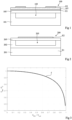
- CMUT transducers have a remarkable property known as the spring softening effect, linked to the non-linear characteristic of the electrostatic force. Essentially, when a DC bias voltage is applied between electrodes E1 and E2 of the transducer, causing a deflection of the membrane, the frequency of the membrane oscillations around the position of equilibrium is shifted downwards. In other words, the resonance frequency of the transducer decreases. This phenomenon is illustrated in Figure 3 .
- Piezoelectric layer 407 for example continuously extends over the entire upper surface of membrane 405.
- Layer 407 is for example directly in contact, by its lower surface, with the upper surface of electrode E2, over the entire upper surface of electrode E2.
- Layer 407 is for example made of PZT (Lead Zirconate Titanate), of PMN-PT (Lead Magnesium Niobate-Lead Titanate), of LiNbO 3 (Lithium Niobate), of AlN (Aluminium Nitride), or of any other piezoelectric material.
- the thickness of piezoelectric layer 407 is for example in the range from 300 nm to 5 ⁇ m.
- upper electrode E3 is formed by a conductive layer, for example, metallic, located above a portion only of the upper surface of cavity 403. More particularly, in the shown example, electrode E3 has, in top view, the shape of a ring-shaped strip located vertically in line with a peripheral portion of cavity 403. Thus, a central portion of cavity 403 is not covered with electrode E3. As a variation (not shown), upper electrode E3 could be localized above the central portion of the cavity only. Electrode E3 is for example directly in contact, by its lower surface, with the upper surface of piezoelectric layer 407. Electrode E3 is for example made of aluminum, titanium, platinum and/or molybdenum. The thickness of electrode E3 is for example in the range from 200 nm to 1 ⁇ m.
- Control circuit CTRL is connected to electrodes E1, E2, and E3 of the transducer and is configured to, in operation, apply a first control voltage between electrodes E1 and E2, and simultaneously apply a second control voltage different from the first voltage, between electrodes E3 and E2.
- control circuit CTRL is configured to, during an emission phase, apply a DC bias voltage V DC between electrodes E1 and E2, and simultaneously apply an AC excitation voltage V AC between electrodes E3 and E2.
- V DC bias voltage V DC generates an electrostatic force of attraction between electrodes E1 and E2, causing a deflection of membrane 405.
- V AC excitation voltage V AC causes, by piezoelectric effect, an oscillation of the membrane around the position of equilibrium defined by voltage V DC , resulting in the emission of an ultrasound wave.
- DC bias voltage V DC may be maintained, for example, at the same level as the level applied during the emission phase.
- Control circuit CTRL is then configured to read an AC voltage generated between electrodes E3 and E2 under the effect of a received ultrasound wave.
- the level of the DC bias voltage V DC applied between electrodes E1 and E2 determines the resonance frequency and thus the main operating frequency of the transducer. More particularly, increasing DC bias voltage V DC results in decreasing the apparent mechanical stiffness of membrane 405, due to the above-mentioned spring softening effect, thus causing a decrease in the resonance frequency of the transducer.
- Control circuit CTRL enables to adapt the level of DC bias voltage V DC to modify the resonance frequency of the transducer, for example, according to the type of body to be analyzed or to the type of information which is desired to be obtained.
- the frequency of AC excitation voltage V AC may be accordingly adjusted to correspond to the resonance frequency of the transducer.
- intermediate electrode E2 is used as a potential reference common to control voltages V DC and V AC .
- Electrode E2 may be coupled, for example, connected, to a node of application of a fixed reference potential of the device, for example, the ground.
- Figure 5 is a diagram illustrating the behavior of an embodiment of an ultrasonic transducer of the type described in relation with Figure 4 .
- the present example considers a transducer in which:
- the eigenfrequency of the transducer is in the order of 40 kHz in vacuum, and in the order of 33 kHz in air, which is the targeted medium of use of the transducer.
- the collapse frequency of the membrane that is, the voltage threshold V DC resulting from the placing into contact of the membrane with the bottom of the cavity, is approximately 32.5 V.
- the diagram of Figure 5 comprises six curves C0, C10, C20, C25, C29, and C31 respectively showing, for six different levels of DC bias voltage V DC applied between electrodes E1 and E2 of the transducer, the variation of the acoustic pressure emitted by the membrane during an emission phase (in ordinates, in Pa) according to the frequency of the AC excitation voltage V AC applied between electrodes E3 and E2 of the transducer (in abscissas, in kHz).
- the emitted pressure is measured 1 mm above the membrane, for an AC voltage V AC having a 1-V amplitude.
- Curves C0, C10, C20, C25, C29, and C31 have been measured for respective levels of DC bias voltage V DC in the order of 0 V, 10 V, 20 V, 25 V, 29 V, and 31 V.
- the resonance frequency of the transducer non-linearly decreases when bias voltage V DC increases, from approximately 33 kHz for a zero voltage V DC , to approximately 21 kHz for a voltage V DC in the order of 31 V. It can further be shown in Figure 5 that the acoustic pressure level at the resonance frequency of the transducer remains substantially constant when the level of voltage V DC varies.
- the transducer of the example of Figure 5 may for example be used in a distance measurement device of motor vehicle parking radar type. Shifting downwards the operating frequency of the transducer may in particular enable to increase the maximum obstacle detection distance, at the cost of a lower measurement accuracy.
- the operating frequency may however be increased by decreasing bias voltage V DC when the distance to the obstacle decreases, to improve the accuracy of the measurement.
- Figure 6 is a diagram illustrating the behavior of another embodiment of an ultrasonic transducer of the type described in relation with Figure 4 .
- the eigenfrequency of the transducer is in the order of 3.5 MHz in vacuum, and in the order of 2.9 MHz in water, which is the targeted medium of use of the transducer.
- the collapse voltage of the membrane is approximately 59 V.
- the diagram of Figure 6 comprises six curves C0, C20, C35, C45, C53, and C56 respectively showing, for six different levels of DC bias voltage V DC applied between electrodes E1 and E2 of the transducer, the variation of the acoustic pressure emitted by the membrane during an emission phase (in ordinates, in kPa) according to the frequency of the AC excitation voltage V AC applied between electrodes E3 and E2 of the transducer (in abscissas, in MHz).
- the emitted pressure is measured 100 ⁇ m above the membrane, for an AC voltage V AC having a 1-V amplitude.
- Curves C0, C20, C35, C45, C53, and C56 have been measured for respective levels of DC bias voltage V DC in the order of 0 V, 20 V, 35 V, 45 V, 53 V, and 56 V.
- the resonance frequency of the transducer non-linearly decreases when bias voltage V DC increases, from approximately 2.9 MHz for a zero voltage V DC , to approximately 1.75 MHz for a voltage V DC in the order of 56 V. It can further again be observed in Figure 6 that the acoustic pressure level at the resonance frequency of the transducer remains substantially constant when the level of voltage V DC varies.
- the transducer of the example of Figure 6 may for example be used in medical imaging applications.
- Figure 7 is a cross-section view schematically showing an alternative embodiment of the ultrasonic inspection device described in relation with Figure 4 .
- Transducer 700 differs from transducer 400 essentially in that, in transducer 700, an electrically-insulating layer 709, for example, made of silicon oxide, forms an interface between membrane 405 and intermediate electrode E2.
- Layer 700 for example continuously extends over the entire surface of membrane 405. In the shown example, layer 700 is in contact, by its lower surface, with the upper surface of membrane 405 and, by its upper surface, with the lower surface of electrode E2, over substantially the entire surface of the membrane.
- membrane 405 is made of a conductive material or of a doped semiconductor material, for example, made of doped silicon, and defines an additional intermediate electrode E2' of the transducer.
- electrode E2' may be formed by a conductive layer, for example, metallic, attached to the membrane and arranged above cavity 403, between the upper surface of membrane 405 and the lower surface of dielectric layer 709, or also on the lower surface side of membrane 405.
- Control circuit CTRL is connected to electrodes E1, E2, E2', and E3 of the transducer and is configured to, in operation, apply a first control voltage between electrodes E1 and E2', and simultaneously apply a second control voltage, different from the first voltage, between electrodes E3 and E2.
- V AC and V DC may in particular enable to use, within control circuit CTRL, insulated circuits (not detailed) to respectively generate voltages V AC and V DC .
- electrodes E1, E2, E3 and, possibly, E2' may have other patterns, in top view, than those indicated in the present disclosure.
- the described devices may be used for other applications that the setting of the operating frequency of the transducers.
- the described embodiments are not limited to the examples of use described hereabove, where the voltage applied to electrode E1 is a DC bias voltage used to set the resonance frequency of the transducer, and the voltage applied to electrode E3 is an AC voltage for exciting the piezoelectric layer of the transducer.
Landscapes
- Engineering & Computer Science (AREA)
- Mechanical Engineering (AREA)
- Transducers For Ultrasonic Waves (AREA)
- Investigating Or Analyzing Materials By The Use Of Ultrasonic Waves (AREA)
- Ultra Sonic Daignosis Equipment (AREA)
Claims (11)
- Eine Ultraschallvorrichtung, aufweisend einen Ultraschallwandler (400; 700; 800), der Folgendes aufweist:- eine Membran (405), aufgehängt über einem Hohlraum (403), der auf der Seite der oberen Oberfläche eines Substrats (401) angeordnet ist;- eine piezoelektrische Schicht (407), befestigt an einer Oberfläche der Membran (405);- eine erste Elektrode (E1), angeordnet auf der unteren Oberflächenseite des Hohlraums (403); und- eine zweite Elektrode (E3), angeordnet auf der oberen Oberflächenseite des Hohlraums (403), und in Kontakt mit der piezoelektrischen Schicht (407),die Vorrichtung ferner aufweisend eine Steuerschaltung (CTRL), verbunden mit der ersten (E1) und der zweiten (E3) Elektrode und in der Lage zum gleichzeitigen Anlegen einer ersten Steuerspannung (VDC) an die erste Elektrode (E1) und einer zweiten Steuerspannung (VAC), die sich von der ersten Spannung unterscheidet, an die zweite Elektrode (E3),wobei die Steuerschaltung (CTRL) konfiguriert, während einer Phase der Emission einer Ultraschallwelle, zum Anlegen einer Gleichstrom-Vorspannung als die erste Steuerspannung (VDC) an die erste Elektrode (E1) und zum Anlegen einer Wechselstrom-Erregungsspannung als die zweite Steuerspannung (VAC) an die zweite Elektrode (E3),und wobei die Steuerschaltung (CTRL) konfiguriert, während einer Phase des Empfangs einer Ultraschallwelle, zum Anlegen einer Gleichstrom-Vorspannung als die erste Steuerspannung (VDC) an die erste Elektrode (E1) und zum Lesen einer Wechselspannung, die an der zweiten Elektrode (E3) generiert wird unter der Wirkung der empfangenen Ultraschallwelle.
- Die Vorrichtung nach Anspruch 1, wobei der Ultraschallwandler (400; 700; 800) ferner eine dritte Elektrode (E2; E2') auf der oberen Oberflächenseite des Hohlraums (403) aufweist, wobei die erste Steuerspannung (VDC) angelegt wird zwischen der ersten Elektrode (E1) und der dritten Elektrode (E2; E2').
- Die Vorrichtung nach Anspruch 2, wobei die zweite Steuerspannung (VAC) angelegt wird zwischen der zweiten Elektrode (E3) und der dritten Elektrode (E2).
- Die Vorrichtung nach Anspruch 2, wobei der Ultraschallwandler (700) ferner eine vierte Elektrode (E2) aufweist, die isoliert ist von der dritten Elektrode (E2') auf der oberen Oberflächenseite des Hohlraums (403), wobei die zweite Steuerspannung (VAC) angelegt wird zwischen der zweiten Elektrode (E3) und der vierten Elektrode (E2).
- Die Vorrichtung nach einem der Ansprüche 1 bis 4, wobei die piezoelektrische Schicht (407) angeordnet ist auf der oberen Oberfläche der Membran (405) und die zweite Elektrode (E3) in Kontakt mit der oberen Oberfläche der piezoelektrischen Schicht (407) ist.
- Die Vorrichtung nach Anspruch 5 und Anspruch 3, wobei die dritte Elektrode (E2) in Kontakt mit der unteren Oberfläche der piezoelektrischen Schicht (407) ist.
- Die Vorrichtung nach Anspruch 5 und Anspruch 4, wobei die vierte Elektrode (E2) über der dritten Elektrode (E2') angeordnet ist und in Kontakt mit der unteren Oberfläche der piezoelektrischen Schicht (407) ist.
- Die Vorrichtung nach einem der Ansprüche 1 bis 7, wobei die Steuerschaltung (CTRL) in der Lage ist zum Variieren der Höhe der Gleichstrom-Vorspannung (VDC), die an die erste Elektrode (E1) angelegt wird, und zwar zum Variieren der Resonanzfrequenz des Ultraschallwandlers.
- Die Vorrichtung nach einem der Ansprüche 1 bis 8, wobei die Membran (405) aus einem Halbleitermaterial gebildet wird.
- Die Vorrichtung nach einem der Ansprüche 1 bis 9, wobei das Substrat (401) aus einem Halbleitermaterial gebildet wird.
- Die Vorrichtung nach einem der Ansprüche 1 bis 10, wobei der Hohlraum (403) in einer dielektrischen Schicht (402) ausgebildet ist, die die obere Oberfläche des Substrats (401) beschichtet.
Applications Claiming Priority (2)
| Application Number | Priority Date | Filing Date | Title |
|---|---|---|---|
| US201962889623P | 2019-08-21 | 2019-08-21 | |
| PCT/IB2020/000715 WO2021033030A1 (en) | 2019-08-21 | 2020-08-18 | Frequency-tunable ultrasonic device |
Publications (3)
| Publication Number | Publication Date |
|---|---|
| EP4017650A1 EP4017650A1 (de) | 2022-06-29 |
| EP4017650B1 true EP4017650B1 (de) | 2025-06-04 |
| EP4017650C0 EP4017650C0 (de) | 2025-06-04 |
Family
ID=72709634
Family Applications (1)
| Application Number | Title | Priority Date | Filing Date |
|---|---|---|---|
| EP20785590.9A Active EP4017650B1 (de) | 2019-08-21 | 2020-08-18 | Frequenzabstimmbare ultraschallvorrichtung |
Country Status (4)
| Country | Link |
|---|---|
| US (1) | US12440868B2 (de) |
| EP (1) | EP4017650B1 (de) |
| CN (1) | CN114269484B (de) |
| WO (1) | WO2021033030A1 (de) |
Families Citing this family (6)
| Publication number | Priority date | Publication date | Assignee | Title |
|---|---|---|---|---|
| EP3815795A1 (de) * | 2019-10-30 | 2021-05-05 | Nederlandse Organisatie voor toegepast- natuurwetenschappelijk Onderzoek TNO | Membranwandler mit verbesserter bandbreite |
| EP3992760B1 (de) * | 2021-03-30 | 2024-09-25 | Siemens Healthineers AG | Vorrichtung und verfahren zum bedienen eines medizinischen bildgebungsgeräts |
| CN115889150A (zh) * | 2021-08-13 | 2023-04-04 | 上海新微技术研发中心有限公司 | 基于直流偏置的接收压电微机械超声换能器系统及方法 |
| US20230266183A1 (en) * | 2022-02-24 | 2023-08-24 | Qorvo Us, Inc. | Integrated piezoresitive (pzr) and piezoelectric micromachined ultrasonic transducer (pmut) device and related high-voltage (hv) / bipolar-cmos-dmos (bcd) processing methods |
| US20240390939A1 (en) * | 2023-05-27 | 2024-11-28 | Flora Innovations Inc. | Piezoelectric Transducer Providing Haptic Feedback |
| EP4559588A1 (de) * | 2023-11-21 | 2025-05-28 | Dyconex AG | Ultraschallwandlervorrichtung |
Citations (2)
| Publication number | Priority date | Publication date | Assignee | Title |
|---|---|---|---|---|
| US20130162102A1 (en) * | 2011-12-27 | 2013-06-27 | Firas Sammoura | Tunable ultrasound transducers |
| EP3459646A1 (de) * | 2017-09-22 | 2019-03-27 | Koninklijke Philips N.V. | Ultraschallwandlervorrichtung und verfahren zur steuerung davon |
Family Cites Families (6)
| Publication number | Priority date | Publication date | Assignee | Title |
|---|---|---|---|---|
| FR2835981B1 (fr) * | 2002-02-13 | 2005-04-29 | Commissariat Energie Atomique | Microresonateur mems a ondes acoustiques de volume accordable |
| JP4839099B2 (ja) * | 2006-03-03 | 2011-12-14 | オリンパスメディカルシステムズ株式会社 | マイクロマシンプロセスにより製造された超音波振動子、超音波振動子装置、その体腔内超音波診断装置、及びその制御方法 |
| US9660170B2 (en) * | 2012-10-26 | 2017-05-23 | Fujifilm Dimatix, Inc. | Micromachined ultrasonic transducer arrays with multiple harmonic modes |
| US10441975B2 (en) | 2016-05-10 | 2019-10-15 | Invensense, Inc. | Supplemental sensor modes and systems for ultrasonic transducers |
| KR102369434B1 (ko) * | 2017-04-19 | 2022-03-03 | 삼성전기주식회사 | 체적 음향 공진기 및 이의 제조방법 |
| CN108787406A (zh) * | 2018-05-21 | 2018-11-13 | 广州汇专工具有限公司 | 超声波换能器及其制作方法 |
-
2020
- 2020-08-18 US US17/636,673 patent/US12440868B2/en active Active
- 2020-08-18 CN CN202080058508.0A patent/CN114269484B/zh active Active
- 2020-08-18 EP EP20785590.9A patent/EP4017650B1/de active Active
- 2020-08-18 WO PCT/IB2020/000715 patent/WO2021033030A1/en not_active Ceased
Patent Citations (2)
| Publication number | Priority date | Publication date | Assignee | Title |
|---|---|---|---|---|
| US20130162102A1 (en) * | 2011-12-27 | 2013-06-27 | Firas Sammoura | Tunable ultrasound transducers |
| EP3459646A1 (de) * | 2017-09-22 | 2019-03-27 | Koninklijke Philips N.V. | Ultraschallwandlervorrichtung und verfahren zur steuerung davon |
Also Published As
| Publication number | Publication date |
|---|---|
| EP4017650A1 (de) | 2022-06-29 |
| CN114269484A (zh) | 2022-04-01 |
| WO2021033030A1 (en) | 2021-02-25 |
| EP4017650C0 (de) | 2025-06-04 |
| US12440868B2 (en) | 2025-10-14 |
| US20220314274A1 (en) | 2022-10-06 |
| CN114269484B (zh) | 2023-10-27 |
Similar Documents
| Publication | Publication Date | Title |
|---|---|---|
| EP4017650B1 (de) | Frequenzabstimmbare ultraschallvorrichtung | |
| US8076821B2 (en) | Multiple element electrode cMUT devices and fabrication methods | |
| JP6618938B2 (ja) | トランスデューサおよびトランスデューサアレイ | |
| US11813639B2 (en) | Electrode arrangement for a pMUT and pMUT transducer array | |
| CN102639258B (zh) | 用于电容式机电变换器的控制设备以及控制电容式机电变换器的方法 | |
| US8758253B2 (en) | Ultrasonic probe and ultrasonic diagnostic apparatus using the same | |
| JP5183640B2 (ja) | 超音波撮像装置 | |
| JP5341909B2 (ja) | 電圧フィードバックを施した容量性マイクロマシン加工超音波変換器 | |
| US6443901B1 (en) | Capacitive micromachined ultrasonic transducers | |
| CN101772383B (zh) | 具有高k电介质的cmut | |
| CN109092649B (zh) | 静电-压电混合驱动收发一体化cmut及其使用方法和制备方法 | |
| CN110265544A (zh) | 压电传感器及制备方法、进行指纹识别的方法及电子设备 | |
| CN101669375B (zh) | 静电容量式传感器以及超声波摄像装置 | |
| US8727994B2 (en) | Cell and channel of ultrasonic transducer, and ultrasonic transducer including the same | |
| Guldiken et al. | Dual-electrode CMUT with non-uniform membranes for high electromechanical coupling coefficient and high bandwidth operation | |
| WO2008038454A1 (en) | Ultrasonic probe and ultrasonic imaging device | |
| Xia et al. | High-SPL and low-driving-voltage pMUTs by sputtered potassium sodium niobate | |
| CN220027664U (zh) | 一种超声换能器 | |
| CN109848021B (zh) | 超声波器件以及超声波测量装置 | |
| JP5026770B2 (ja) | 超音波探触子及び超音波診断装置 | |
| EP4559588A1 (de) | Ultraschallwandlervorrichtung | |
| US7923893B2 (en) | 3-1 mode capacitive membrane ultrasound transducer | |
| EP4360767A1 (de) | Ultraschallwandler und verfahren zur herstellung eines ultraschallwandlers |
Legal Events
| Date | Code | Title | Description |
|---|---|---|---|
| STAA | Information on the status of an ep patent application or granted ep patent |
Free format text: STATUS: UNKNOWN |
|
| STAA | Information on the status of an ep patent application or granted ep patent |
Free format text: STATUS: THE INTERNATIONAL PUBLICATION HAS BEEN MADE |
|
| PUAI | Public reference made under article 153(3) epc to a published international application that has entered the european phase |
Free format text: ORIGINAL CODE: 0009012 |
|
| STAA | Information on the status of an ep patent application or granted ep patent |
Free format text: STATUS: REQUEST FOR EXAMINATION WAS MADE |
|
| 17P | Request for examination filed |
Effective date: 20220125 |
|
| AK | Designated contracting states |
Kind code of ref document: A1 Designated state(s): AL AT BE BG CH CY CZ DE DK EE ES FI FR GB GR HR HU IE IS IT LI LT LU LV MC MK MT NL NO PL PT RO RS SE SI SK SM TR |
|
| DAV | Request for validation of the european patent (deleted) | ||
| DAX | Request for extension of the european patent (deleted) | ||
| STAA | Information on the status of an ep patent application or granted ep patent |
Free format text: STATUS: EXAMINATION IS IN PROGRESS |
|
| 17Q | First examination report despatched |
Effective date: 20240220 |
|
| GRAP | Despatch of communication of intention to grant a patent |
Free format text: ORIGINAL CODE: EPIDOSNIGR1 |
|
| STAA | Information on the status of an ep patent application or granted ep patent |
Free format text: STATUS: GRANT OF PATENT IS INTENDED |
|
| INTG | Intention to grant announced |
Effective date: 20250314 |
|
| GRAS | Grant fee paid |
Free format text: ORIGINAL CODE: EPIDOSNIGR3 |
|
| GRAA | (expected) grant |
Free format text: ORIGINAL CODE: 0009210 |
|
| STAA | Information on the status of an ep patent application or granted ep patent |
Free format text: STATUS: THE PATENT HAS BEEN GRANTED |
|
| AK | Designated contracting states |
Kind code of ref document: B1 Designated state(s): AL AT BE BG CH CY CZ DE DK EE ES FI FR GB GR HR HU IE IS IT LI LT LU LV MC MK MT NL NO PL PT RO RS SE SI SK SM TR |
|
| REG | Reference to a national code |
Ref country code: GB Ref legal event code: FG4D |
|
| REG | Reference to a national code |
Ref country code: CH Ref legal event code: EP |
|
| REG | Reference to a national code |
Ref country code: DE Ref legal event code: R096 Ref document number: 602020052337 Country of ref document: DE |
|
| REG | Reference to a national code |
Ref country code: IE Ref legal event code: FG4D |
|
| U01 | Request for unitary effect filed |
Effective date: 20250701 |
|
| U07 | Unitary effect registered |
Designated state(s): AT BE BG DE DK EE FI FR IT LT LU LV MT NL PT RO SE SI Effective date: 20250722 |
|
| U20 | Renewal fee for the european patent with unitary effect paid |
Year of fee payment: 6 Effective date: 20250730 |
|
| PG25 | Lapsed in a contracting state [announced via postgrant information from national office to epo] |
Ref country code: ES Free format text: LAPSE BECAUSE OF FAILURE TO SUBMIT A TRANSLATION OF THE DESCRIPTION OR TO PAY THE FEE WITHIN THE PRESCRIBED TIME-LIMIT Effective date: 20250604 |
|
| PG25 | Lapsed in a contracting state [announced via postgrant information from national office to epo] |
Ref country code: NO Free format text: LAPSE BECAUSE OF FAILURE TO SUBMIT A TRANSLATION OF THE DESCRIPTION OR TO PAY THE FEE WITHIN THE PRESCRIBED TIME-LIMIT Effective date: 20250904 Ref country code: GR Free format text: LAPSE BECAUSE OF FAILURE TO SUBMIT A TRANSLATION OF THE DESCRIPTION OR TO PAY THE FEE WITHIN THE PRESCRIBED TIME-LIMIT Effective date: 20250905 |
|
| PG25 | Lapsed in a contracting state [announced via postgrant information from national office to epo] |
Ref country code: PL Free format text: LAPSE BECAUSE OF FAILURE TO SUBMIT A TRANSLATION OF THE DESCRIPTION OR TO PAY THE FEE WITHIN THE PRESCRIBED TIME-LIMIT Effective date: 20250604 |
|
| PG25 | Lapsed in a contracting state [announced via postgrant information from national office to epo] |
Ref country code: HR Free format text: LAPSE BECAUSE OF FAILURE TO SUBMIT A TRANSLATION OF THE DESCRIPTION OR TO PAY THE FEE WITHIN THE PRESCRIBED TIME-LIMIT Effective date: 20250604 |
|
| PG25 | Lapsed in a contracting state [announced via postgrant information from national office to epo] |
Ref country code: RS Free format text: LAPSE BECAUSE OF FAILURE TO SUBMIT A TRANSLATION OF THE DESCRIPTION OR TO PAY THE FEE WITHIN THE PRESCRIBED TIME-LIMIT Effective date: 20250904 |