EP4017446B1 - Gel-blockierende verbindungsanordnung für einen absorbierenden unterdruckverband - Google Patents
Gel-blockierende verbindungsanordnung für einen absorbierenden unterdruckverband Download PDFInfo
- Publication number
- EP4017446B1 EP4017446B1 EP20757412.0A EP20757412A EP4017446B1 EP 4017446 B1 EP4017446 B1 EP 4017446B1 EP 20757412 A EP20757412 A EP 20757412A EP 4017446 B1 EP4017446 B1 EP 4017446B1
- Authority
- EP
- European Patent Office
- Prior art keywords
- fluid
- absorbent
- dressing
- tube
- manifolding
- Prior art date
- Legal status (The legal status is an assumption and is not a legal conclusion. Google has not performed a legal analysis and makes no representation as to the accuracy of the status listed.)
- Active
Links
Images


Classifications
-
- A—HUMAN NECESSITIES
- A61—MEDICAL OR VETERINARY SCIENCE; HYGIENE
- A61M—DEVICES FOR INTRODUCING MEDIA INTO, OR ONTO, THE BODY; DEVICES FOR TRANSDUCING BODY MEDIA OR FOR TAKING MEDIA FROM THE BODY; DEVICES FOR PRODUCING OR ENDING SLEEP OR STUPOR
- A61M1/00—Suction or pumping devices for medical purposes; Devices for carrying-off, for treatment of, or for carrying-over, body-liquids; Drainage systems
- A61M1/90—Negative pressure wound therapy devices, i.e. devices for applying suction to a wound to promote healing, e.g. including a vacuum dressing
- A61M1/91—Suction aspects of the dressing
- A61M1/912—Connectors between dressing and drainage tube
-
- A—HUMAN NECESSITIES
- A61—MEDICAL OR VETERINARY SCIENCE; HYGIENE
- A61F—FILTERS IMPLANTABLE INTO BLOOD VESSELS; PROSTHESES; DEVICES PROVIDING PATENCY TO, OR PREVENTING COLLAPSING OF, TUBULAR STRUCTURES OF THE BODY, e.g. STENTS; ORTHOPAEDIC, NURSING OR CONTRACEPTIVE DEVICES; FOMENTATION; TREATMENT OR PROTECTION OF EYES OR EARS; BANDAGES, DRESSINGS OR ABSORBENT PADS; FIRST-AID KITS
- A61F13/00—Bandages or dressings; Absorbent pads
- A61F13/02—Adhesive bandages or dressings
- A61F13/0203—Adhesive bandages or dressings with fluid retention members
- A61F13/0206—Adhesive bandages or dressings with fluid retention members with absorbent fibrous layers, e.g. woven or non-woven absorbent pads or island dressings
- A61F13/0209—Adhesive bandages or dressings with fluid retention members with absorbent fibrous layers, e.g. woven or non-woven absorbent pads or island dressings comprising superabsorbent material
-
- A—HUMAN NECESSITIES
- A61—MEDICAL OR VETERINARY SCIENCE; HYGIENE
- A61F—FILTERS IMPLANTABLE INTO BLOOD VESSELS; PROSTHESES; DEVICES PROVIDING PATENCY TO, OR PREVENTING COLLAPSING OF, TUBULAR STRUCTURES OF THE BODY, e.g. STENTS; ORTHOPAEDIC, NURSING OR CONTRACEPTIVE DEVICES; FOMENTATION; TREATMENT OR PROTECTION OF EYES OR EARS; BANDAGES, DRESSINGS OR ABSORBENT PADS; FIRST-AID KITS
- A61F13/00—Bandages or dressings; Absorbent pads
- A61F13/02—Adhesive bandages or dressings
- A61F13/0203—Adhesive bandages or dressings with fluid retention members
- A61F13/022—Adhesive bandages or dressings with fluid retention members having more than one layer with different fluid retention characteristics
-
- A—HUMAN NECESSITIES
- A61—MEDICAL OR VETERINARY SCIENCE; HYGIENE
- A61F—FILTERS IMPLANTABLE INTO BLOOD VESSELS; PROSTHESES; DEVICES PROVIDING PATENCY TO, OR PREVENTING COLLAPSING OF, TUBULAR STRUCTURES OF THE BODY, e.g. STENTS; ORTHOPAEDIC, NURSING OR CONTRACEPTIVE DEVICES; FOMENTATION; TREATMENT OR PROTECTION OF EYES OR EARS; BANDAGES, DRESSINGS OR ABSORBENT PADS; FIRST-AID KITS
- A61F13/00—Bandages or dressings; Absorbent pads
- A61F13/05—Bandages or dressings; Absorbent pads specially adapted for use with sub-pressure or over-pressure therapy, wound drainage or wound irrigation, e.g. for use with negative-pressure wound therapy [NPWT]
-
- A—HUMAN NECESSITIES
- A61—MEDICAL OR VETERINARY SCIENCE; HYGIENE
- A61M—DEVICES FOR INTRODUCING MEDIA INTO, OR ONTO, THE BODY; DEVICES FOR TRANSDUCING BODY MEDIA OR FOR TAKING MEDIA FROM THE BODY; DEVICES FOR PRODUCING OR ENDING SLEEP OR STUPOR
- A61M1/00—Suction or pumping devices for medical purposes; Devices for carrying-off, for treatment of, or for carrying-over, body-liquids; Drainage systems
- A61M1/90—Negative pressure wound therapy devices, i.e. devices for applying suction to a wound to promote healing, e.g. including a vacuum dressing
- A61M1/91—Suction aspects of the dressing
- A61M1/915—Constructional details of the pressure distribution manifold
-
- A—HUMAN NECESSITIES
- A61—MEDICAL OR VETERINARY SCIENCE; HYGIENE
- A61F—FILTERS IMPLANTABLE INTO BLOOD VESSELS; PROSTHESES; DEVICES PROVIDING PATENCY TO, OR PREVENTING COLLAPSING OF, TUBULAR STRUCTURES OF THE BODY, e.g. STENTS; ORTHOPAEDIC, NURSING OR CONTRACEPTIVE DEVICES; FOMENTATION; TREATMENT OR PROTECTION OF EYES OR EARS; BANDAGES, DRESSINGS OR ABSORBENT PADS; FIRST-AID KITS
- A61F13/00—Bandages or dressings; Absorbent pads
- A61F2013/00361—Plasters
- A61F2013/00727—Plasters means for wound humidity control
- A61F2013/00748—Plasters means for wound humidity control with hydrocolloids or superabsorbers
-
- A—HUMAN NECESSITIES
- A61—MEDICAL OR VETERINARY SCIENCE; HYGIENE
- A61F—FILTERS IMPLANTABLE INTO BLOOD VESSELS; PROSTHESES; DEVICES PROVIDING PATENCY TO, OR PREVENTING COLLAPSING OF, TUBULAR STRUCTURES OF THE BODY, e.g. STENTS; ORTHOPAEDIC, NURSING OR CONTRACEPTIVE DEVICES; FOMENTATION; TREATMENT OR PROTECTION OF EYES OR EARS; BANDAGES, DRESSINGS OR ABSORBENT PADS; FIRST-AID KITS
- A61F13/00—Bandages or dressings; Absorbent pads
- A61F13/15—Absorbent pads, e.g. sanitary towels, swabs or tampons for external or internal application to the body; Supporting or fastening means therefor; Tampon applicators
- A61F2013/15008—Absorbent pads, e.g. sanitary towels, swabs or tampons for external or internal application to the body; Supporting or fastening means therefor; Tampon applicators characterized by the use
- A61F2013/15073—Absorbent pads, e.g. sanitary towels, swabs or tampons for external or internal application to the body; Supporting or fastening means therefor; Tampon applicators characterized by the use as drapes
Definitions
- the present disclosure relates generally to the field of wound therapy, and more particularly to dressings for use in negative pressure wound therapy.
- Negative pressure wound therapy is a type of wound therapy that involves applying negative pressure (relative to atmospheric pressure) to a wound bed to promote wound healing.
- negative pressure relative to atmospheric pressure
- a dressing is sealed over a wound bed and air is pumped out of the dressing to create a negative pressure at the wound bed.
- wound exudate and other fluid is pumped out of the dressing and collected by a therapy system.
- One implementation of the present invention is a dressing as set out in claim 1.
- Optional features are set out in the dependent claims.
- a system comprising: the dressing; a tube coupled to the dressing; a connection assembly, wherein the tube is coupled to the dressing by the connection assembly; a pump pneumatically communicable with the dressing via the tube; and a dye in the tube configured to provide an indication representative of fluid in the tube.
- a negative pressure wound therapy (NPWT) system 100 is shown.
- the NPWT system 100 includes a pump 102 pneumatically communicable with a dressing 104 via tube 106.
- the tube 106 is coupled to the dressing 104 by a connection assembly 108.
- the dressing 104 is shown as sealed over a wound bed 109.
- the wound bed 109 is a tissue wound of a patient, for example a laceration, burn, sore, trauma wound, chronic wound, etc.
- the dressing 104 allows a negative pressure to be maintained at the wound bed 109 while absorbing fluid from the wound bed 109.
- the dressing 104 thereby provides both negative pressure and a high level of fluid absorption.
- the dressing 104 is shown to include drape 112, a manifold layer 110, a wound contact layer 114, and absorbent deposits 116. It should be understood that the dressing 104 is one example of an absorbent negative pressure dressing and that many embodiments are possible, for example as shown and described in U.S. Provisional Patent Application 62/732,285, filed September 17, 2018 .
- the drape 112 is configured to seal the wound contact layer 114, the manifold layer 110, and the absorbent deposits 116 over the wound bed 109.
- the drape 112 may include an adhesive ring coupleable to the patient's skin surrounding the wound bed 109.
- the drape 112 may include a material that substantially prevents leaking of air therethrough to facilitate creation and maintenance of a negative pressure at the manifold layer 110 (i.e., in a volume between the drape 112 and the wound bed 109).
- the drape 112 may also include a material with a high moisture vapor transfer rate to facilitate evaporation of fluid from the absorbent deposits 116 to the ambient air through the drape 112.
- the wound contact layer 114 provides an interface between the dressing 104 and a wound.
- the wound contact layer 114 may be configured to prevent ingrowth of the wound bed 109 to the dressing and to facilitate removal of the dressing 104 while minimizing damage to the healing tissue of the wound bed 109.
- the wound contact layer 114 includes a film, for example a silicone film.
- the wound contact layer 114 may be perforated or otherwise formed to allow for the flow of air and fluid therethrough.
- the manifold layer 110 is configured to allow airflow therethrough to facilitate the distribution of negative pressure across the wound bed 109.
- the manifold layer 110 may include an open-celled foam, for example a foam material marketed as GRANUFOAM TM by ACELITY TM .
- the manifold layer 110 is also configured to allow fluid to flow therethrough, from the wound bed 109 to the absorbent deposits 116.
- the absorbent deposits 116 are configured to absorb fluid, for example wound exudate from the wound bed 109.
- the absorbent deposits 116 may include a superabsorbent material.
- Various arrangements and configurations of the absorbent deposits 116 are included in various embodiments.
- the absorbent deposits 116 may be included as a superabsorbent laminate positioned between the drape 112 and the manifold layer 110, with channels extending therethrough to allow airflow therethrough.
- various configurations of absorbent dressings 104 are contemplated by the present disclosure and can be compatible with the connection assembly 108, which is described in detail with reference to FIGS. 2-9 .
- the absorbent deposits 116 and the dressing 104 are configured such that the absorbent deposits 116 absorb fluid to approximately a full capacity of the absorbent deposits 116 before fluid passes into or is absorbed by the connection assembly 108 as described below.
- connection assembly 108 is configured to couple the dressing 104 to a tube 106, which is coupled to a pump 102.
- the connection assembly 108 is positioned at a hole extending through the drape 112 such that the connection assembly 108 is in fluid communication with the manifold layer 110.
- the connection assembly 108 is configured to allow airflow between the manifold layer 110 and the pump 102 while restricting the flow of fluid therebetween.
- the tube 106 is configured to provide an airway that allows air to flow from the connection assembly 108 to the pump 102. In some examples, for example as shown in FIG. 10 and described in detail with reference thereto, the tube 106 is configured to prevent the flow of fluid therethrough.
- the pump 102 is operable to pump air out of the dressing 104 via the tube 106 to create and maintain a negative pressure at the wound bed 109.
- the pump 102 may be electrically powered and the NPWT system 100 includes power systems and control circuitry to power and control operation of the pump 102.
- the NPWT system 100 may include one or more pressure sensors or various other sensors that collect data used to control the pump 102 to maintain a negative pressure at the wound bed 109.
- the pump 102 may be manually-powered, such that a user may manipulate the pump 102 to draw air out of the dressing 104 as desired by the user.
- the pump 102 may be spring-loaded to gradually pull air from the dressing 104 for a duration of time following a compression of the pump 102 by the user.
- the NPWT system 100 is thereby configured to provide a negative pressure at the wound bed 109 while also facilitating absorption of fluid from the wound bed 109 by the dressing 104.
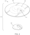
- connection assembly 108 includes a connection pad 200 and an absorbent manifolding structure 202.
- the connection pad 200 is configured to couple the dressing 104 to the tube 106.
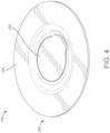
- the connection pad 200 includes an outer ring 204 that surrounds a center dimple 206.
- the outer ring 204 is configured to be coupled to the drape 112. When the outer ring 204 is coupled to the drape, the center dimple 206 extends away from the drape 112. The center dimple 206 thereby defines an inner volume 208 between the center dimple 206 and a plane defined by the outer ring 204.
- the connection pad 200 also includes a tube conduit 210 configured to receive the tube 106.
- the absorbent manifolding structure (disc, insert, layer, etc.) 202 is formed to have a shape that substantially matches a shape of the inner volume 208. Accordingly, the absorbent manifolding structure 202 is configured to fit substantially within the inner volume 208 and the inner volume 208 is configured to receive the absorbent manifolding structure 202. In the example shown, the absorbent manifolding structure 202 substantially fills the inner volume 208. By fitting within the inner volume 208, the absorbent manifolding structure 202 can be selectively included or not included with the NPWT system 100 without requiring a change in the design or manufacturing process for the dressing 104 or the connection pad 200.
- the absorbent manifolding structure 202 is positioned in the inner volume 208 and positioned between the tube conduit 210 and the dressing 104 such that airflow from the dressing 104 to the tube 106 must pass through the absorbent manifolding structure 202.
- the absorbent manifolding structure 202 is configured to allow airflow therethrough (i.e., between the dressing 104 and the tube 106) when the absorbent manifolding structure 202 has not absorbed a threshold amount of fluid, and to prevent airflow therethrough when the absorbent manifolding structure 202 has absorbed more than a threshold amount of fluid.
- the absorbent manifolding structure 202 is shown to include a sintered polymer material (e.g., sintered polyethylene) mixed with a superabsorbent material.
- the sintered polymer material is formed with pores (channels, spaces, airways, etc.) such that air and fluid can pass through the sintered polymer material. Each pore may have a size within a range between approximately 20 microns and 60 microns.
- the superabsorbent material is dispersed in the sintered polymer material and is configured to absorb fluid and swell when in contact with fluid.
- the absorbent manifolding structure 202 when the superabsorbent material swells to absorb fluid (e.g., more than a threshold amount of fluid), the swollen superabsorbent material closes (gel-blocks, fills, blocks, obstructs, etc.) the pores of the sintered polymer material and restricts the flow of air and fluid through the absorbent manifolding structure 202.
- the absorbent manifolding structure 202 is thereby configured to allow airflow therethrough when substantially dry, while substantially preventing the flow of air and fluid therethrough when more than a threshold amount of fluid is absorbed by the sintered polymer material.
- the air flow through the absorbent manifolding structure 202 may be between approximately 160 ml/min and 480ml/min at an air pressure of 300 Pa.
- the absorbent manifolding structure 202 thereby facilitates the pump 102 in drawing a negative pressure at the dressing 104 while substantially preventing fluid from the wound bed 109 from reaching the pump 102 (damaging the pump 102, contaminating the pump 102, etc.).
- the blocking effect provided by the superabsorbent material may be localized within the absorbent manifolding structure 202 to areas (regions, spots, etc.) of the absorbent manifolding structure 202 in contact with fluid.
- a first region of the absorbent manifolding structure 202 may include swollen superabsorbent (having absorbed fluid) that blocks the flow of air and fluid through the first region, while a second region of the absorbent manifolding structure 202 is substantially dry (i.e., not in contact with a significant amount of fluid) and therefore allows air to flow through the second region.
- This regional independence may allow airflow through the absorbent manifolding structure 202 to remain open for an increased amount of time.
- the absorbent manifolding structure 202 includes a fluid-activated dye.
- the dye is released and/or changes color in response to contact with fluid.
- the connection pad 200 may be translucent or transparent such that the dye is visible through the connection pad 200.
- the absorbent manifolding structure 202 may thereby be configured to provide a visual indication that the absorbent manifolding structure 202 has absorbed fluid to a user (patient, caregiver, etc.).
- the tube 106 includes a fluid-activated dye configured to release and/or change color in response to contact with fluid, such that a change in color in the tube indicates that fluid has passed through the absorbent manifolding structure 202.
- the inclusion of a dye may thereby facilitate a user in determining when to remove the dressing 104 and/or make other changes to wound therapy.
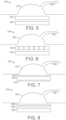
- connection assembly 108 includes the connection pad 200, a felted foam layer 500, and a gel-blocking sintered polymer layer 502 positioned between the connection pad 200 and the felted foam layer 500.
- the felted foam layer 500 and the gel-blocking sintered polymer layer 502 are positioned under the connection pad 200 (i.e., between the center dimple 206 and the dressing 104.
- the felted foam layer 500 and the gel-blocking sintered polymer layer 502 are formed to fit within the center dimple 206 similar to the examples of FIGS. 2-4 .
- the felted foam layer 500 is configured to allow airflow therethrough and to resist the flow of fluid therethrough such that fluid in the dressing 104 is directed to the absorbent deposits 116 or other wicking or absorbent structure of the dressing 104 when absorbent capacity is available in the dressing 104.
- the felted foam layer 500 thereby substantially minimizes or restricts the flow of fluid into the connection assembly 108 when absorbent capacity is available in the dressing 104.
- the felted foam layer 500 is configured to allow fluid to pass therethrough from the manifold layer 110 to the gel-blocking sintered polymer layer 502. Accordingly, passage of fluid through the felted foam layer 500 is associated with a full dressing 104.
- the felted foam layer 500 may include three to five times felted foam, where the foam is a same or similar foam as the manifold layer 110 (i.e., processed to be permanently compressed to a fraction of the original thickness of the foam material of the manifold layer 110).
- the gel-blocking sintered polymer layer 502 is configured to allow air to flow therethrough when the gel-blocking sintered polymer layer 502 has absorbed less than a threshold amount of fluid, and to prevent air and fluid from flowing therethrough when the gel-blocking sintered polymer layer 502 has absorbed more than a threshold amount of fluid.
- the gel-blocking sintered polymer layer 502 includes a sintered polymer material (e.g., sintered polyethylene) mixed with a superabsorbent material.
- the sintered polymer material is formed with pores (channels, spaces, airways, etc.) such that air and fluid can pass through the sintered polymer material. Each pore may have a size within a range between approximately 20 microns and 60 microns.
- the superabsorbent material is dispersed in the sintered polymer material and is configured to absorb fluid and swell when in contact with fluid.
- the superabsorbent material of the gel-blocking sintered polymer layer 502 swells to absorb fluid (e.g., more than a threshold amount of fluid)
- the swollen superabsorbent material closes (gel-blocks, fills, blocks, obstructs, etc.) the pores of the sintered polymer material and restricts the flow of air and fluid through the absorbent manifolding structure 202.
- the absorbent manifolding structure 202 is thereby configured to allow airflow therethrough when substantially dry, while substantially preventing the flow of air and fluid therethrough when more than a threshold amount of fluid is absorbed by the sintered polymer material.
- the gel-blocking sintered polymer layer 502 may also include a fluid-activated dye configured to provide a visual indication of fluid reaching the gel-blocking sintered polymer layer 502.
- the gel-blocking effect provided by the superabsorbent material may be localized within the gel-blocking sintered polymer layer 502 to regions (areas, spots, etc.) of the gel-blocking sintered polymer layer 502 in contact with fluid.
- a first region of the gel-blocking sintered polymer layer 502 may include swollen superabsorbent (having absorbed fluid) that blocks the flow of air and fluid through the first region, while a second region of the gel-blocking sintered polymer layer 502 is substantially dry (i.e., not in contact with a significant amount of fluid) and therefore allows air to flow through the second region.
- This regional independence may allow airflow through the gel-blocking sintered polymer layer 502 to remain possible for an increased amount of time.
- connection assembly 108 includes the connection assembly, the felted foam layer 500 and a perforated superabsorbent laminate 600 positioned between the felted foam layer 500 and the perforated superabsorbent laminate 600.
- the felted foam layer 500 and the perforated superabsorbent laminate 600 are positioned under the connection pad 200 (i.e., between the center dimple 206 and the dressing 104.
- the felted foam layer 500 and/or the perforated superabsorbent laminate 600 are formed to fit within the center dimple 206 similar to the examples of FIGS. 2-4 .
- the perforated superabsorbent laminate 600 is configured to allow air to flow therethrough when the perforated superabsorbent laminate 600 has absorbed less than a threshold amount of fluid, and to prevent air and fluid from flowing therethrough when the perforated superabsorbent laminate 600 has absorbed more than a threshold amount of fluid.
- the perforated superabsorbent laminate 600 includes one or more membranes (e.g., films, hydrophilic membranes, etc.) and a superabsorbent material.
- the perforated superabsorbent laminate 600 includes a hydrophilic membrane layer, a superabsorbent material positioned on the hydrophilic membrane layer, and a film layer coupled to the hydrophilic foam layer and configured to confine the superabsorbent material between the film layer and the hydrophilic membrane layer.
- a superabsorbent laminate is described in U.S. Patent Application No. 62/788,036, filed January 3, 2019 .
- the perforated superabsorbent laminate 600 includes multiple perforations (holes, channels, airways, pores, etc.) extending therethrough (e.g., approximately 5 perforations, approximately 10 perforations, approximately 100 perforations, etc.).
- the perforations may have a diameter between approximately 1mm and 2mm and may be spaced to maintain structural integrity of the perforated superabsorbent laminate 600.
- the perforations may be distributed within a radial spacing of approximately 4-5mm over the perforated superabsorbent laminate 600. The perforations allow air to flow through the perforated superabsorbent laminate 600 via the perforations.
- the superabsorbent material of the perforated superabsorbent laminate 600 absorbs fluid, the superabsorbent material swells, including into the perforations to narrow or close (block, fill, shut) the perforations.
- the perforated superabsorbent laminate 600 substantially prevents the flow of air and fluid through the perforated superabsorbent laminate 600. Additionally, swelling of the superabsorbent material may be localized to regions where fluid is in contact with the superabsorbent laminate 600 (i.e., where fluid has passed through the felted foam layer 500).
- a first region of the superabsorbent laminate 600 is exposed to fluid and the superabsorbent material at the first region is swollen to block one or more perforations of the first region, while a second region of the superabsorbent laminate is not exposed to fluid and the superabsorbent material at the second region is not swollen such that perforations at the second region remain open.
- airflow is blocked at the first region where airflow is allowed via the perforations of the second region.
- the perforations may be characterized as an array of fluidly-activated micro-valves.
- connection assembly 108 includes the connection pad 200, the felted foam layer 500, a first microporous film layer 702 coupled to the felted foam layer 500, and a second microporous film layer 700 positioned between the felted foam layer 600 and the connection pad 200.
- the felted foam layer 500 is positioned between the first microporous film layer 702 and the second microporous film layer 700.
- the first microporous film layer 702 and the second microporous film layer 700 are configured to allow air to flow therethrough.
- the first microporous film layer 702 and the second microporous film layer 700 are also configured to resist a flow of fluid therethrough (i.e., allows a low rate of fluid to pass therethrough).
- the first microporous film layer 702, the felted foam layer 500, and the second microporous film layer 700 may be positioned below the connection pad 200 as shown in FIG. 7 or may be positioned in the inner volume 208 of the connection pad 200 similar to the embodiments of FIGS. 2-4 .
- connection assembly 108 includes the connection pad 200, the felted foam layer 500, a superabsorbent fiber layer 800 positioned between the felted foam layer 500 and the connection pad 200 and a fusible fiber layer 802 positioned between the felted foam layer 500 and the connection pad 200.
- the fusible fiber layer 802 is configured to couple the superabsorbent fiber layer 800 to the felted foam layer 500. In some manufacturing processes, the fusible fiber layer 802 may be omitted and the superabsorbent fiber layer 800 may adhere directly to the felted foam layer 500.
- the felted foam layer 500, the superabsorbent fiber layer 800, and the fusible fiber layer 802 may be positioned below the connection pad 200 as shown in FIG. 8 and/or may be positioned in the inner volume 208 of the connection pad 200 similar to the example of FIGS. 2-4 .
- the superabsorbent fiber layer 800 is open to airflow when dry, i.e., such that air can flow therethrough from the felted foam layer 500 to the connection pad 200.
- the superabsorbent fiber layer 800 is configured to absorb fluid and swell to retain the fluid. When fluid is absorbed by the superabsorbent fiber layer 800, the swelling of the superabsorbent fiber layer 800 closes airways through the superabsorbent fiber layer 800, thereby substantially preventing airflow through the superabsorbent fiber layer 800.
- the superabsorbent fiber layer 800 may include a superabsorbent fiber sold as Oasis Type 2577 Super Absorbent Fibre by Technical Absorbents Limited or a superabsorbent fiber sold as M631/113 by Freudenberg.
- a superabsorbent material (e.g., in a granular form) may be deposited on the felted foam layer 500.
- the superabsorbent material may be suspended in an organic dry solvent such as a ketone or alcohol and may be coated on the felted foam layer 500, and may behave in a similar manner as the superabsorbent fiber layer 800 of FIG. 8 .
- the superabsorbent material may be arranged as a cross-linked hydrogel printed (deposited, etc.) on the felted foam layer 500 in a pattern that allows airflow therethrough while having sufficient coverage to block the flow of fluid therethrough when swollen.
- a perforated hydrogel sheet or a hydrogel coated mesh may be included to allow air to flow through the sheet or mesh when dry and substantially prevent the flow of air and fluid through the sheet or mesh when in contact with at least a threshold amount of fluid.
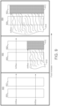
- FIG. 9 an illustration depicting the behavior of the second example of the connection assembly 108 (i.e., as in FIG. 5 ) when in contact with fluid, according to an example which is useful for understanding the claimed subject matter but does not form part of the claimed subject matter.
- FIG. 9 shows three frames, arranged in chronological order to show change over time.
- the felted foam layer 500 and the gel-blocking sintered polymer layer 502 are not exposed to fluid. Accordingly, airflow is permitted through all regions (portions, areas, etc.) of the felted foam layer 500 and the gel-blocking sintered polymer layer 502.
- the pump 102 can draw air out of the manifold layer 110 via the tube 106 and connection assembly 108 at a maximum airflow rate to establish a negative pressure at the wound bed 109.
- the felted foam layer 500 is exposed to fluid 910.
- a maximum absorption capacity of the dressing 104 e.g., of the absorbent deposits 116
- the fluid 910 has passed through the felted foam layer 500 to the gel-blocking sintered polymer layer 502.
- the superabsorbent material of the gel-blocking sintered polymer layer 502 has swollen in a gel-blocked region 912 of the sintered polymer layer 502.
- the gel-blocked region 912 substantially prevents the flow of air and fluid through the gel-blocked region 912 of the gel-blocking sintered polymer layer 502.
- the gel-blocked region 912 is only a portion of the gel-blocking sintered polymer layer 502. Accordingly, airflow is still permitted through other areas of the gel-blocking sintered polymer layer 502 as indicated in the second frame 902.
- the rate of airflow through the connection assembly 108 to the pump 102 may be lower in the second frame 902 relative to the first frame 900.
- the amount of fluid 910 at the felted foam layer 500 and the gel-blocking sintered polymer layer 502 continues to increase.
- substantially the entirety of the gel-blocking sintered polymer layer 502 is exposed to fluid.
- the superabsorbent material has swollen across substantially the entirety of the gel-blocking sintered polymer layer 502. Accordingly, the gel-blocked region 912 has expanded relative to the second frame 902 to block airflow through substantially the entirety of the gel-blocking sintered polymer layer 502. The flow of air and fluid through the gel-blocking sintered polymer layer 502 (and therefore the connection assembly 108) is thereby substantially prevented.
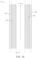
- FIG. 10 a cross-sectional view of an example of the tube 106 is shown, according to an example which is useful for understanding the claimed subject matter but does not form part of the claimed subject matter.
- the tube 106 may be used with various embodiments of the NPWT system 100 including with various embodiments of the connection assembly 108.
- the tube 106 is configured to be coupled to the tube conduit 210 of the connection pad 200 and the pump 102.
- the tube 106 includes a hydrophobic outer ring 1000 and a fluid-activated inner ring 1002.
- a central channel 1004 extends approximately along a central axis of the fluid-activated inner ring 1002.
- the tube 106 is configured to allow airflow therethrough (i.e., through the central channel 1004) when the fluid-activated inner ring 1002 is substantially dry and to block the flow of fluid and air therethrough when the fluid-activated inner ring 1002 is exposed to a threshold amount of fluid.
- the hydrophobic outer ring 1000 includes a plasticized PVC or polyurethane tube (e.g., a suitable material for standard medical-grade tubing).
- the hydrophobic outer ring 1000 surrounds and is coupled to the fluid-activated inner ring 1002.
- the fluid-activated inner ring 1002 is positioned within the hydrophobic outer ring 1000.
- the hydrophobic outer ring 1000 and fluid-activated inner ring 1002 may make up a full length of the tube 106 or may be included as one or more segments of the tube 106 (e.g., added as an accessory to an existing tubeset).
- the hydrophobic outer ring 1000 is configured to swell in response to contact with fluid.
- the hydrophobic outer ring 1000 may include a superabsorbent material configured to absorb fluid and swell to retain the fluid.
- the hydrophobic outer ring 1000 may be configured to resist expansion, i.e., such that the fluid-activated inner ring 1002 primarily expands into the central channel 1004 when exposed to fluid. Accordingly, as fluid enters the tube 106, the cross-sectional area of the central channel 1004 is reduced partially or completely by the fluid-activated inner ring 1002, thereby reducing the rate of air or fluid flow through the central channel 1004 and/or preventing the flow of air or fluid through the central channel 1004.
- the fluid-activated inner ring 1002 when substantially dry, is configured to provides structural support that prevents the fluid-activated inner ring 1002 (and, in some examples, the hydrophobic outer ring 1000) from collapsing inward due to a pressure differential between the ambient air and the interior of the central channel 1004 (as established by the pump 102).
- the fluid-activated inner ring 1002 is configured to soften when in contact with fluid, thereby reducing the rigidity of the fluid-activated inner ring 1002 and the ability of the fluid-activated inner ring 1002 to provide structural support for the tube 106.
- the hydrophobic outer ring 1000 includes perforations that allow communication of ambient air pressure to the fluid-activated inner ring 1002, which may cause the fluid-activated inner ring 1002 to collapse under a pressure differential between the ambient air and the interior of the central channel 1004 (i.e., without requiring collapse of the hydrophobic outer ring 1000).
- the hydrophobic outer ring 1000 may collapse under the pressure differential when the structural support of the fluid-activated inner ring 1002 is reduced.
- the pressure differential between the ambient air and the central channel 1004 causes the fluid-activated inner ring 1002 (and, in some examples, the hydrophobic outer ring 1000) and to collapse inwards, reducing or eliminating a cross-sectional area of the central channel 1004.
- the flow of air and fluid is thereby restricted or prevented by the tube 106 in response to fluid entering the tube 106.
- the closing of the central channel 1004 may be made reversible.
- the fluid-activated inner ring 1002 may return to its original form as fluid returns to the dressing 104 from the tube 106 (e.g., drawn into the superabsorbent deposits 116 as fluid from the superabsorbent deposits 116 evaporates to the ambient environment).
- the tube 106 includes a fluid-activated dye configured to be released and/or to change color in response to exposure to fluid.
- the tube 106 may be transparent or translucent such that the dye is visible in the tube. The dye may thereby facilitate a user in determining when a dressing should be removed and/or planning other modifications to wound therapy for the wound bed 109.
Landscapes
- Health & Medical Sciences (AREA)
- Heart & Thoracic Surgery (AREA)
- Animal Behavior & Ethology (AREA)
- Biomedical Technology (AREA)
- Vascular Medicine (AREA)
- Life Sciences & Earth Sciences (AREA)
- Engineering & Computer Science (AREA)
- General Health & Medical Sciences (AREA)
- Public Health (AREA)
- Veterinary Medicine (AREA)
- Anesthesiology (AREA)
- Hematology (AREA)
- Media Introduction/Drainage Providing Device (AREA)
- External Artificial Organs (AREA)
Claims (9)
- Verband (104), umfassend:eine Verteilerschicht (110);ein Abdecktuch (112), das mit der Verteilerschicht (110) gekoppelt und konfiguriert ist, um die Verteilerschicht über einer Wunde (109) abzudichten, wobei das Abdecktuch (112) eine hindurchführende Öffnung aufweist;ein Verbindungspad (200), das an der Öffnung positioniert und konfiguriert ist, um den Verband (104) mit einem Schlauch (106) zu verbinden, wobei das Verbindungspad (200) umfasst:einen Außenring (204), der mit dem Abdecktuch (112) gekoppelt ist; undeine zentrale Vertiefung (206), die sich von dem Abdecktuch (112) weg erstreckt und ein Volumen (208) zwischen der zentralen Vertiefung (206) und einer durch den äußeren Ring (204) definierten Ebene definiert; undeine absorbierende Verteilerstruktur (202), die zwischen der zentralen Vertiefung (206) und der Verteilerschicht (110) positioniert ist und so geformt ist, dass sie im Wesentlichen der Form des Volumens (208) entspricht, wobei die absorbierende Verteilerstruktur (202) ein hydrophobes poröses Element umfasst, das mit einem luftdurchlässigen superabsorbierenden Material kombiniert ist, das so konfiguriert ist, dass es bei Kontakt mit Fluiden eine Gelblockierung bewirkt.
- Verband nach Anspruch 1, wobei die absorbierende Verteilerstruktur (202) konfiguriert ist, um
eine Passage von Luft zu erlauben, wenn die absorbierende Verteilerstruktur mit weniger als einer Schwellenmenge an Fluid in Kontakt ist. - Verband nach Anspruch 1, wobei die absorbierende Verteilerstruktur (202) ein Polymer-Verteilermaterial und ein superabsorbierendes Material umfasst.
- Verband nach Anspruch 3, wobei das superabsorbierende Material konfiguriert ist, um in Reaktion auf Kontakt mit Fluid aufzuquellen.
- Verband nach Anspruch 4, wobei die absorbierende Verteilerstruktur (202) die Passage von Luft einschränkt, wenn das superabsorbierende Material aufgequollen ist.
- Verband nach Anspruch 5, wobei die absorbierende Verteilerstruktur (202) die Passage von Luft durch einen ersten Bereich der absorbierenden Verteilerstruktur verhindert und die Passage von Luft durch einen zweiten Bereich der absorbierenden Verteilerstruktur ermöglicht, wenn das superabsorbierende Material im ersten Bereich aufgequollen ist und das superabsorbierende Material im zweiten Bereich nicht aufgequollen ist.
- Verband nach Anspruch 3, wobei die absorbierende Verteilerstruktur (202) ein gesintertes Polyethylen gemischt mit dem superabsorbierenden Material umfasst.
- Verband nach Anspruch 1, wobei die absorbierende Verteilerstruktur (202) einen durch Fluid aktivierten Farbstoff umfasst, der so konfiguriert ist, dass er eine Farbänderung der absorbierenden Verteilerstruktur bewirkt, wenn Fluid die absorbierende Verteilerstruktur füllt.
- System (100), umfassend:den Verband (104) nach einem der vorstehenden Ansprüche;einen Schlauch (106), der mit dem Verband (104) gekoppelt ist;eine Verbindungsanordnung (108), wobei der Schlauch (106) durch die Verbindungsanordnung (108) mit dem Verband (104) gekoppelt ist;eine Pumpe (102), die über den Schlauch (106) pneumatisch mit dem Verband (104) kommunizieren kann; undeinen Farbstoff im Schlauch, der so konfiguriert ist, dass er eine Anzeige liefert, die für das Fluid im Schlauch repräsentativ ist (106).
Applications Claiming Priority (2)
| Application Number | Priority Date | Filing Date | Title |
|---|---|---|---|
| US201962889454P | 2019-08-20 | 2019-08-20 | |
| PCT/IB2020/057545 WO2021033077A1 (en) | 2019-08-20 | 2020-08-11 | Gel-blocking connection assembly for absorbent negative pressure dressing |
Publications (2)
| Publication Number | Publication Date |
|---|---|
| EP4017446A1 EP4017446A1 (de) | 2022-06-29 |
| EP4017446B1 true EP4017446B1 (de) | 2025-02-12 |
Family
ID=72088343
Family Applications (1)
| Application Number | Title | Priority Date | Filing Date |
|---|---|---|---|
| EP20757412.0A Active EP4017446B1 (de) | 2019-08-20 | 2020-08-11 | Gel-blockierende verbindungsanordnung für einen absorbierenden unterdruckverband |
Country Status (5)
| Country | Link |
|---|---|
| US (1) | US12102748B2 (de) |
| EP (1) | EP4017446B1 (de) |
| JP (1) | JP2022545354A (de) |
| CN (1) | CN114222551A (de) |
| WO (1) | WO2021033077A1 (de) |
Families Citing this family (1)
| Publication number | Priority date | Publication date | Assignee | Title |
|---|---|---|---|---|
| CN118304560A (zh) * | 2024-03-13 | 2024-07-09 | 华夏乘黄(北京)健康科技有限公司 | 经皮给药治疗仪真空系统及经皮给药治疗仪 |
Citations (2)
| Publication number | Priority date | Publication date | Assignee | Title |
|---|---|---|---|---|
| US20140188060A1 (en) * | 2013-01-03 | 2014-07-03 | Kci Licensing, Inc. | Moisture absorbing seal |
| US20140316358A1 (en) * | 2013-03-14 | 2014-10-23 | Kci Licensing, Inc. | Fluid collection canister with integrated moisture trap |
Family Cites Families (148)
| Publication number | Priority date | Publication date | Assignee | Title |
|---|---|---|---|---|
| US1355846A (en) | 1920-02-06 | 1920-10-19 | David A Rannells | Medical appliance |
| US2547758A (en) | 1949-01-05 | 1951-04-03 | Wilmer B Keeling | Instrument for treating the male urethra |
| US2632443A (en) | 1949-04-18 | 1953-03-24 | Eleanor P Lesher | Surgical dressing |
| GB692578A (en) | 1949-09-13 | 1953-06-10 | Minnesota Mining & Mfg | Improvements in or relating to drape sheets for surgical use |
| US2682873A (en) | 1952-07-30 | 1954-07-06 | Johnson & Johnson | General purpose protective dressing |
| NL189176B (nl) | 1956-07-13 | 1900-01-01 | Hisamitsu Pharmaceutical Co | Pleister op basis van een synthetische rubber. |
| US2969057A (en) | 1957-11-04 | 1961-01-24 | Brady Co W H | Nematodic swab |
| US3066672A (en) | 1960-09-27 | 1962-12-04 | Jr William H Crosby | Method and apparatus for serial sampling of intestinal juice |
| US3367332A (en) | 1965-08-27 | 1968-02-06 | Gen Electric | Product and process for establishing a sterile area of skin |
| US3520300A (en) | 1967-03-15 | 1970-07-14 | Amp Inc | Surgical sponge and suction device |
| US3568675A (en) | 1968-08-30 | 1971-03-09 | Clyde B Harvey | Fistula and penetrating wound dressing |
| US3682180A (en) | 1970-06-08 | 1972-08-08 | Coilform Co Inc | Drain clip for surgical drain |
| BE789293Q (fr) | 1970-12-07 | 1973-01-15 | Parke Davis & Co | Pansement medico-chirugical pour brulures et lesions analogues |
| US3826254A (en) | 1973-02-26 | 1974-07-30 | Verco Ind | Needle or catheter retaining appliance |
| DE2527706A1 (de) | 1975-06-21 | 1976-12-30 | Hanfried Dr Med Weigand | Einrichtung zum einleiten von kontrastmittel in einen kuenstlichen darmausgang |
| DE2640413C3 (de) | 1976-09-08 | 1980-03-27 | Richard Wolf Gmbh, 7134 Knittlingen | Katheter-Überwachungsgerät |
| NL7710909A (nl) | 1976-10-08 | 1978-04-11 | Smith & Nephew | Samengestelde hechtstrook. |
| GB1562244A (en) | 1976-11-11 | 1980-03-05 | Lock P M | Wound dressing materials |
| US4080970A (en) | 1976-11-17 | 1978-03-28 | Miller Thomas J | Post-operative combination dressing and internal drain tube with external shield and tube connector |
| US4139004A (en) | 1977-02-17 | 1979-02-13 | Gonzalez Jr Harry | Bandage apparatus for treating burns |
| US4184510A (en) | 1977-03-15 | 1980-01-22 | Fibra-Sonics, Inc. | Valued device for controlling vacuum in surgery |
| US4165748A (en) | 1977-11-07 | 1979-08-28 | Johnson Melissa C | Catheter tube holder |
| US4245637A (en) | 1978-07-10 | 1981-01-20 | Nichols Robert L | Shutoff valve sleeve |
| SE414994B (sv) | 1978-11-28 | 1980-09-01 | Landstingens Inkopscentral | Venkateterforband |
| WO1980001139A1 (en) | 1978-12-06 | 1980-06-12 | Svedman Paul | Device for treating tissues,for example skin |
| US4266545A (en) | 1979-04-06 | 1981-05-12 | Moss James P | Portable suction device for collecting fluids from a closed wound |
| US4284079A (en) | 1979-06-28 | 1981-08-18 | Adair Edwin Lloyd | Method for applying a male incontinence device |
| US4261363A (en) | 1979-11-09 | 1981-04-14 | C. R. Bard, Inc. | Retention clips for body fluid drains |
| US4569348A (en) | 1980-02-22 | 1986-02-11 | Velcro Usa Inc. | Catheter tube holder strap |
| WO1981002516A1 (fr) | 1980-03-11 | 1981-09-17 | E Schmid | Coussin pour comprimer un element de peau greffe |
| US4297995A (en) | 1980-06-03 | 1981-11-03 | Key Pharmaceuticals, Inc. | Bandage containing attachment post |
| US4333468A (en) | 1980-08-18 | 1982-06-08 | Geist Robert W | Mesentery tube holder apparatus |
| US4465485A (en) | 1981-03-06 | 1984-08-14 | Becton, Dickinson And Company | Suction canister with unitary shut-off valve and filter features |
| US4392853A (en) | 1981-03-16 | 1983-07-12 | Rudolph Muto | Sterile assembly for protecting and fastening an indwelling device |
| US4373519A (en) | 1981-06-26 | 1983-02-15 | Minnesota Mining And Manufacturing Company | Composite wound dressing |
| US4392858A (en) | 1981-07-16 | 1983-07-12 | Sherwood Medical Company | Wound drainage device |
| US4419097A (en) | 1981-07-31 | 1983-12-06 | Rexar Industries, Inc. | Attachment for catheter tube |
| AU550575B2 (en) | 1981-08-07 | 1986-03-27 | Richard Christian Wright | Wound drainage device |
| SE429197B (sv) | 1981-10-14 | 1983-08-22 | Frese Nielsen | Anordning for behandling av sar |
| DE3146266A1 (de) | 1981-11-21 | 1983-06-01 | B. Braun Melsungen Ag, 3508 Melsungen | Kombinierte vorrichtung fuer eine medizinische saugdrainage |
| US4551139A (en) | 1982-02-08 | 1985-11-05 | Marion Laboratories, Inc. | Method and apparatus for burn wound treatment |
| US4475909A (en) | 1982-05-06 | 1984-10-09 | Eisenberg Melvin I | Male urinary device and method for applying the device |
| DE3361779D1 (en) | 1982-07-06 | 1986-02-20 | Dow Corning | Medical-surgical dressing and a process for the production thereof |
| NZ206837A (en) | 1983-01-27 | 1986-08-08 | Johnson & Johnson Prod Inc | Thin film adhesive dressing:backing material in three sections |
| US4548202A (en) | 1983-06-20 | 1985-10-22 | Ethicon, Inc. | Mesh tissue fasteners |
| US4540412A (en) | 1983-07-14 | 1985-09-10 | The Kendall Company | Device for moist heat therapy |
| US4543100A (en) | 1983-11-01 | 1985-09-24 | Brodsky Stuart A | Catheter and drain tube retainer |
| US4525374A (en) | 1984-02-27 | 1985-06-25 | Manresa, Inc. | Treating hydrophobic filters to render them hydrophilic |
| CA1286177C (en) | 1984-05-03 | 1991-07-16 | Smith And Nephew Associated Companies Plc | Adhesive wound dressing |
| US4897081A (en) | 1984-05-25 | 1990-01-30 | Thermedics Inc. | Percutaneous access device |
| US5215522A (en) | 1984-07-23 | 1993-06-01 | Ballard Medical Products | Single use medical aspirating device and method |
| GB8419745D0 (en) | 1984-08-02 | 1984-09-05 | Smith & Nephew Ass | Wound dressing |
| US4872450A (en) | 1984-08-17 | 1989-10-10 | Austad Eric D | Wound dressing and method of forming same |
| US4826494A (en) | 1984-11-09 | 1989-05-02 | Stryker Corporation | Vacuum wound drainage system |
| US4655754A (en) | 1984-11-09 | 1987-04-07 | Stryker Corporation | Vacuum wound drainage system and lipids baffle therefor |
| US4605399A (en) | 1984-12-04 | 1986-08-12 | Complex, Inc. | Transdermal infusion device |
| US5037397A (en) | 1985-05-03 | 1991-08-06 | Medical Distributors, Inc. | Universal clamp |
| US4640688A (en) | 1985-08-23 | 1987-02-03 | Mentor Corporation | Urine collection catheter |
| US4710165A (en) | 1985-09-16 | 1987-12-01 | Mcneil Charles B | Wearable, variable rate suction/collection device |
| US4758220A (en) | 1985-09-26 | 1988-07-19 | Alcon Laboratories, Inc. | Surgical cassette proximity sensing and latching apparatus |
| US4733659A (en) | 1986-01-17 | 1988-03-29 | Seton Company | Foam bandage |
| WO1987004626A1 (en) | 1986-01-31 | 1987-08-13 | Osmond, Roger, L., W. | Suction system for wound and gastro-intestinal drainage |
| US4838883A (en) | 1986-03-07 | 1989-06-13 | Nissho Corporation | Urine-collecting device |
| JPS62281965A (ja) | 1986-05-29 | 1987-12-07 | テルモ株式会社 | カテ−テルおよびカテ−テル用固定部材 |
| GB8621884D0 (en) | 1986-09-11 | 1986-10-15 | Bard Ltd | Catheter applicator |
| GB2195255B (en) | 1986-09-30 | 1991-05-01 | Vacutec Uk Limited | Apparatus for vacuum treatment of an epidermal surface |
| US4743232A (en) | 1986-10-06 | 1988-05-10 | The Clinipad Corporation | Package assembly for plastic film bandage |
| DE3634569A1 (de) | 1986-10-10 | 1988-04-21 | Sachse Hans E | Kondomkatheter, ein harnroehrenkatheter zur verhinderung von aufsteigenden infektionen |
| JPS63135179A (ja) | 1986-11-26 | 1988-06-07 | 立花 俊郎 | 薬物の経皮投与具 |
| GB8628564D0 (en) | 1986-11-28 | 1987-01-07 | Smiths Industries Plc | Anti-foaming agent suction apparatus |
| GB8706116D0 (en) | 1987-03-14 | 1987-04-15 | Smith & Nephew Ass | Adhesive dressings |
| US4787888A (en) | 1987-06-01 | 1988-11-29 | University Of Connecticut | Disposable piezoelectric polymer bandage for percutaneous delivery of drugs and method for such percutaneous delivery (a) |
| US4863449A (en) | 1987-07-06 | 1989-09-05 | Hollister Incorporated | Adhesive-lined elastic condom cathether |
| US5176663A (en) | 1987-12-02 | 1993-01-05 | Pal Svedman | Dressing having pad with compressibility limiting elements |
| US4906240A (en) | 1988-02-01 | 1990-03-06 | Matrix Medica, Inc. | Adhesive-faced porous absorbent sheet and method of making same |
| US4985019A (en) | 1988-03-11 | 1991-01-15 | Michelson Gary K | X-ray marker |
| GB8812803D0 (en) | 1988-05-28 | 1988-06-29 | Smiths Industries Plc | Medico-surgical containers |
| US4919654A (en) | 1988-08-03 | 1990-04-24 | Kalt Medical Corporation | IV clamp with membrane |
| US5000741A (en) | 1988-08-22 | 1991-03-19 | Kalt Medical Corporation | Transparent tracheostomy tube dressing |
| US5059596A (en) | 1989-01-16 | 1991-10-22 | Roussel Uclaf | Azabicyclo compounds |
| GB8906100D0 (en) | 1989-03-16 | 1989-04-26 | Smith & Nephew | Laminates |
| US5527293A (en) | 1989-04-03 | 1996-06-18 | Kinetic Concepts, Inc. | Fastening system and method |
| US5261893A (en) | 1989-04-03 | 1993-11-16 | Zamierowski David S | Fastening system and method |
| US4969880A (en) | 1989-04-03 | 1990-11-13 | Zamierowski David S | Wound dressing and treatment method |
| US5100396A (en) | 1989-04-03 | 1992-03-31 | Zamierowski David S | Fluidic connection system and method |
| US5358494A (en) | 1989-07-11 | 1994-10-25 | Svedman Paul | Irrigation dressing |
| JP2719671B2 (ja) | 1989-07-11 | 1998-02-25 | 日本ゼオン株式会社 | 創傷被覆材 |
| US5232453A (en) | 1989-07-14 | 1993-08-03 | E. R. Squibb & Sons, Inc. | Catheter holder |
| GB2235877A (en) | 1989-09-18 | 1991-03-20 | Antonio Talluri | Closed wound suction apparatus |
| US5134994A (en) | 1990-02-12 | 1992-08-04 | Say Sam L | Field aspirator in a soft pack with externally mounted container |
| US5092858A (en) | 1990-03-20 | 1992-03-03 | Becton, Dickinson And Company | Liquid gelling agent distributor device |
| US5149331A (en) | 1991-05-03 | 1992-09-22 | Ariel Ferdman | Method and device for wound closure |
| US5278100A (en) | 1991-11-08 | 1994-01-11 | Micron Technology, Inc. | Chemical vapor deposition technique for depositing titanium silicide on semiconductor wafers |
| US5645081A (en) | 1991-11-14 | 1997-07-08 | Wake Forest University | Method of treating tissue damage and apparatus for same |
| US5636643A (en) | 1991-11-14 | 1997-06-10 | Wake Forest University | Wound treatment employing reduced pressure |
| US5279550A (en) | 1991-12-19 | 1994-01-18 | Gish Biomedical, Inc. | Orthopedic autotransfusion system |
| US5167613A (en) | 1992-03-23 | 1992-12-01 | The Kendall Company | Composite vented wound dressing |
| FR2690617B1 (fr) | 1992-04-29 | 1994-06-24 | Cbh Textile | Pansement adhesif transparent. |
| GB9302970D0 (en) * | 1993-02-15 | 1993-03-31 | Smith & Nephew | Absorbant dressing,manufacture and use |
| DE4306478A1 (de) | 1993-03-02 | 1994-09-08 | Wolfgang Dr Wagner | Drainagevorrichtung, insbesondere Pleuradrainagevorrichtung, und Drainageverfahren |
| US5342376A (en) | 1993-05-03 | 1994-08-30 | Dermagraphics, Inc. | Inserting device for a barbed tissue connector |
| US6241747B1 (en) | 1993-05-03 | 2001-06-05 | Quill Medical, Inc. | Barbed Bodily tissue connector |
| US5344415A (en) | 1993-06-15 | 1994-09-06 | Deroyal Industries, Inc. | Sterile system for dressing vascular access site |
| US5437651A (en) | 1993-09-01 | 1995-08-01 | Research Medical, Inc. | Medical suction apparatus |
| US5549584A (en) | 1994-02-14 | 1996-08-27 | The Kendall Company | Apparatus for removing fluid from a wound |
| US5556375A (en) | 1994-06-16 | 1996-09-17 | Hercules Incorporated | Wound dressing having a fenestrated base layer |
| US5607388A (en) | 1994-06-16 | 1997-03-04 | Hercules Incorporated | Multi-purpose wound dressing |
| US5664270A (en) | 1994-07-19 | 1997-09-09 | Kinetic Concepts, Inc. | Patient interface system |
| ATE172377T1 (de) | 1994-08-22 | 1998-11-15 | Kinetic Concepts Inc | Wunddrainagevorrichtung |
| DE29504378U1 (de) | 1995-03-15 | 1995-09-14 | MTG Medizinisch, technische Gerätebau GmbH, 66299 Friedrichsthal | Elektronisch geregelte Niedervakuumpumpe für die Thorax- und Wunddrainage |
| GB9509943D0 (en) * | 1995-05-17 | 1995-07-12 | British United Shoe Machinery | Wound dressing |
| GB9523253D0 (en) | 1995-11-14 | 1996-01-17 | Mediscus Prod Ltd | Portable wound treatment apparatus |
| US6135116A (en) | 1997-07-28 | 2000-10-24 | Kci Licensing, Inc. | Therapeutic method for treating ulcers |
| GB9719520D0 (en) | 1997-09-12 | 1997-11-19 | Kci Medical Ltd | Surgical drape and suction heads for wound treatment |
| AU755496B2 (en) | 1997-09-12 | 2002-12-12 | Kci Licensing, Inc. | Surgical drape and suction head for wound treatment |
| US6071267A (en) | 1998-02-06 | 2000-06-06 | Kinetic Concepts, Inc. | Medical patient fluid management interface system and method |
| US6488643B1 (en) | 1998-10-08 | 2002-12-03 | Kci Licensing, Inc. | Wound healing foot wrap |
| US6287316B1 (en) | 1999-03-26 | 2001-09-11 | Ethicon, Inc. | Knitted surgical mesh |
| US6856821B2 (en) | 2000-05-26 | 2005-02-15 | Kci Licensing, Inc. | System for combined transcutaneous blood gas monitoring and vacuum assisted wound closure |
| US7799004B2 (en) | 2001-03-05 | 2010-09-21 | Kci Licensing, Inc. | Negative pressure wound treatment apparatus and infection identification system and method |
| US6991643B2 (en) | 2000-12-20 | 2006-01-31 | Usgi Medical Inc. | Multi-barbed device for retaining tissue in apposition and methods of use |
| CA2400895C (en) | 2000-02-24 | 2011-09-13 | Venetec International, Inc. | Universal catheter anchoring system |
| US6540705B2 (en) | 2001-02-22 | 2003-04-01 | Core Products International, Inc. | Ankle brace providing upper and lower ankle adjustment |
| US7846141B2 (en) | 2002-09-03 | 2010-12-07 | Bluesky Medical Group Incorporated | Reduced pressure treatment system |
| GB0224986D0 (en) | 2002-10-28 | 2002-12-04 | Smith & Nephew | Apparatus |
| GB0325126D0 (en) | 2003-10-28 | 2003-12-03 | Smith & Nephew | Apparatus with heat |
| GB0325120D0 (en) | 2003-10-28 | 2003-12-03 | Smith & Nephew | Apparatus with actives |
| US7909805B2 (en) | 2004-04-05 | 2011-03-22 | Bluesky Medical Group Incorporated | Flexible reduced pressure treatment appliance |
| US8529548B2 (en) | 2004-04-27 | 2013-09-10 | Smith & Nephew Plc | Wound treatment apparatus and method |
| US20080167631A1 (en) * | 2006-10-26 | 2008-07-10 | Greer Steven E | Subatmospheric pressure dressing |
| US8021347B2 (en) | 2008-07-21 | 2011-09-20 | Tyco Healthcare Group Lp | Thin film wound dressing |
| US8007481B2 (en) | 2008-07-17 | 2011-08-30 | Tyco Healthcare Group Lp | Subatmospheric pressure mechanism for wound therapy system |
| US8216198B2 (en) | 2009-01-09 | 2012-07-10 | Tyco Healthcare Group Lp | Canister for receiving wound exudate in a negative pressure therapy system |
| US8251979B2 (en) | 2009-05-11 | 2012-08-28 | Tyco Healthcare Group Lp | Orientation independent canister for a negative pressure wound therapy device |
| KR20110056415A (ko) * | 2008-09-18 | 2011-05-27 | 케이씨아이 라이센싱 인코포레이티드 | 조직 부위에 감압을 작용하는 방법, 시스템 및 다층 드레싱 |
| US20100324516A1 (en) * | 2009-06-18 | 2010-12-23 | Tyco Healthcare Group Lp | Apparatus for Vacuum Bridging and/or Exudate Collection |
| GB201006988D0 (en) * | 2010-04-27 | 2010-06-09 | Smith & Nephew | Suction port |
| CA2844279A1 (en) * | 2011-05-25 | 2012-11-29 | Kci Licensing, Inc. | Wound healing system using positive pressure to promote granulation at a tissue site |
| WO2013064831A1 (en) * | 2011-11-01 | 2013-05-10 | Brightwake Limited | Wound dressings, and yarn useful therein |
| US9427505B2 (en) * | 2012-05-15 | 2016-08-30 | Smith & Nephew Plc | Negative pressure wound therapy apparatus |
| WO2014066057A1 (en) * | 2012-10-25 | 2014-05-01 | Kci Licensing, Inc. | Wound connection pad with pneumatic connection confirmation ability |
| EP3744361B1 (de) * | 2013-10-30 | 2024-07-24 | Solventum Intellectual Properties Company | Absorbierende leitung und system |
| WO2015173547A1 (en) * | 2014-05-14 | 2015-11-19 | Brightwake Limited | Wound dressing |
| WO2017115146A1 (en) * | 2015-12-30 | 2017-07-06 | Smith & Nephew Plc | Absorbent negative pressure wound therapy dressing |
| GB201608099D0 (en) | 2016-05-09 | 2016-06-22 | Convatec Technologies Inc | Negative pressure wound dressing |
| WO2018226624A1 (en) * | 2017-06-07 | 2018-12-13 | Kci Licensing, Inc. | Composite dressings for improved granulation and reduced maceration with negative-pressure treatment |
| US11724020B2 (en) * | 2017-06-14 | 2023-08-15 | Smith & Nephew Plc | Collapsible sheet for wound closure and method of use |
| CN107669405A (zh) * | 2017-09-25 | 2018-02-09 | Ivf哈特曼股份公司 | 用于在潮湿或湿润环境中处理创伤的创伤敷料 |
-
2020
- 2020-08-11 EP EP20757412.0A patent/EP4017446B1/de active Active
- 2020-08-11 JP JP2022508516A patent/JP2022545354A/ja active Pending
- 2020-08-11 CN CN202080057700.8A patent/CN114222551A/zh active Pending
- 2020-08-11 US US17/634,210 patent/US12102748B2/en active Active
- 2020-08-11 WO PCT/IB2020/057545 patent/WO2021033077A1/en not_active Ceased
Patent Citations (2)
| Publication number | Priority date | Publication date | Assignee | Title |
|---|---|---|---|---|
| US20140188060A1 (en) * | 2013-01-03 | 2014-07-03 | Kci Licensing, Inc. | Moisture absorbing seal |
| US20140316358A1 (en) * | 2013-03-14 | 2014-10-23 | Kci Licensing, Inc. | Fluid collection canister with integrated moisture trap |
Also Published As
| Publication number | Publication date |
|---|---|
| US12102748B2 (en) | 2024-10-01 |
| US20220323666A1 (en) | 2022-10-13 |
| WO2021033077A1 (en) | 2021-02-25 |
| EP4017446A1 (de) | 2022-06-29 |
| JP2022545354A (ja) | 2022-10-27 |
| CN114222551A (zh) | 2022-03-22 |
Similar Documents
| Publication | Publication Date | Title |
|---|---|---|
| US20200085632A1 (en) | Absorbent negative pressure dressing | |
| US11648152B2 (en) | Absorbent negative pressure wound therapy dressing | |
| US12453658B2 (en) | Absorbent negative pressure wound therapy dressing | |
| US10695226B2 (en) | Wound dressing and method of treatment | |
| US11806217B2 (en) | Wound dressing | |
| EP3669840B1 (de) | Medizinisches system mit flexibler flüssigkeitsspeicherbrücke | |
| US20210236342A1 (en) | Wound Dressings and Systems with Low-Flow Therapeutic Gas Sources for Topical Wound Therapy and Related Methods | |
| EP2436348B1 (de) | Wundverband mit verbessertem Flüssigkeitstransport | |
| US8672903B2 (en) | Abdominal wound dressing | |
| US20190076298A1 (en) | Wound dressing apparatus with flexible display | |
| JP2020523060A (ja) | 陰圧創傷療法装置 | |
| CN105682623A (zh) | 具有不同大小的穿孔的敷件 | |
| US20220339041A1 (en) | System And Method For Wound Dressing Moisture Management Using Forced Airflow | |
| EP4017446B1 (de) | Gel-blockierende verbindungsanordnung für einen absorbierenden unterdruckverband | |
| JP2023519132A (ja) | 陰圧創傷療法のための装置 | |
| WO2021209950A1 (en) | Dressing with perforated superabsorbent sheet | |
| CN223654052U (zh) | 一种医用聚氨酯敷料及创面负压引流敷料组件 | |
| US12070377B2 (en) | Connection assembly with perforated film layer for absorbent negative pressure dressing | |
| WO2021048754A1 (en) | Simplified negative pressure absorbent dressing |
Legal Events
| Date | Code | Title | Description |
|---|---|---|---|
| STAA | Information on the status of an ep patent application or granted ep patent |
Free format text: STATUS: UNKNOWN |
|
| STAA | Information on the status of an ep patent application or granted ep patent |
Free format text: STATUS: THE INTERNATIONAL PUBLICATION HAS BEEN MADE |
|
| PUAI | Public reference made under article 153(3) epc to a published international application that has entered the european phase |
Free format text: ORIGINAL CODE: 0009012 |
|
| STAA | Information on the status of an ep patent application or granted ep patent |
Free format text: STATUS: REQUEST FOR EXAMINATION WAS MADE |
|
| 17P | Request for examination filed |
Effective date: 20220302 |
|
| AK | Designated contracting states |
Kind code of ref document: A1 Designated state(s): AL AT BE BG CH CY CZ DE DK EE ES FI FR GB GR HR HU IE IS IT LI LT LU LV MC MK MT NL NO PL PT RO RS SE SI SK SM TR |
|
| DAV | Request for validation of the european patent (deleted) | ||
| DAX | Request for extension of the european patent (deleted) | ||
| STAA | Information on the status of an ep patent application or granted ep patent |
Free format text: STATUS: EXAMINATION IS IN PROGRESS |
|
| 17Q | First examination report despatched |
Effective date: 20230816 |
|
| RAP1 | Party data changed (applicant data changed or rights of an application transferred) |
Owner name: 3M INNOVATIVE PROPERTIES COMPANY |
|
| RAP1 | Party data changed (applicant data changed or rights of an application transferred) |
Owner name: SOLVENTUM INTELLECTUAL PROPERTIES COMPANY |
|
| REG | Reference to a national code |
Ref country code: DE Ref legal event code: R079 Free format text: PREVIOUS MAIN CLASS: A61F0013020000 Ipc: A61F0013050000 Ref country code: DE Ref legal event code: R079 Ref document number: 602020045936 Country of ref document: DE Free format text: PREVIOUS MAIN CLASS: A61F0013020000 Ipc: A61F0013050000 |
|
| GRAP | Despatch of communication of intention to grant a patent |
Free format text: ORIGINAL CODE: EPIDOSNIGR1 |
|
| STAA | Information on the status of an ep patent application or granted ep patent |
Free format text: STATUS: GRANT OF PATENT IS INTENDED |
|
| RIC1 | Information provided on ipc code assigned before grant |
Ipc: A61F 13/0203 20240101ALI20240917BHEP Ipc: A61F 13/0206 20240101ALI20240917BHEP Ipc: A61F 13/05 20240101AFI20240917BHEP |
|
| INTG | Intention to grant announced |
Effective date: 20241004 |
|
| GRAS | Grant fee paid |
Free format text: ORIGINAL CODE: EPIDOSNIGR3 |
|
| GRAA | (expected) grant |
Free format text: ORIGINAL CODE: 0009210 |
|
| STAA | Information on the status of an ep patent application or granted ep patent |
Free format text: STATUS: THE PATENT HAS BEEN GRANTED |
|
| AK | Designated contracting states |
Kind code of ref document: B1 Designated state(s): AL AT BE BG CH CY CZ DE DK EE ES FI FR GB GR HR HU IE IS IT LI LT LU LV MC MK MT NL NO PL PT RO RS SE SI SK SM TR |
|
| REG | Reference to a national code |
Ref country code: GB Ref legal event code: FG4D |
|
| REG | Reference to a national code |
Ref country code: CH Ref legal event code: EP |
|
| REG | Reference to a national code |
Ref country code: DE Ref legal event code: R096 Ref document number: 602020045936 Country of ref document: DE |
|
| REG | Reference to a national code |
Ref country code: IE Ref legal event code: FG4D |
|
| REG | Reference to a national code |
Ref country code: NL Ref legal event code: MP Effective date: 20250212 |
|
| PG25 | Lapsed in a contracting state [announced via postgrant information from national office to epo] |
Ref country code: RS Free format text: LAPSE BECAUSE OF FAILURE TO SUBMIT A TRANSLATION OF THE DESCRIPTION OR TO PAY THE FEE WITHIN THE PRESCRIBED TIME-LIMIT Effective date: 20250512 |
|
| PG25 | Lapsed in a contracting state [announced via postgrant information from national office to epo] |
Ref country code: FI Free format text: LAPSE BECAUSE OF FAILURE TO SUBMIT A TRANSLATION OF THE DESCRIPTION OR TO PAY THE FEE WITHIN THE PRESCRIBED TIME-LIMIT Effective date: 20250212 |
|
| PG25 | Lapsed in a contracting state [announced via postgrant information from national office to epo] |
Ref country code: PL Free format text: LAPSE BECAUSE OF FAILURE TO SUBMIT A TRANSLATION OF THE DESCRIPTION OR TO PAY THE FEE WITHIN THE PRESCRIBED TIME-LIMIT Effective date: 20250212 |
|
| PG25 | Lapsed in a contracting state [announced via postgrant information from national office to epo] |
Ref country code: ES Free format text: LAPSE BECAUSE OF FAILURE TO SUBMIT A TRANSLATION OF THE DESCRIPTION OR TO PAY THE FEE WITHIN THE PRESCRIBED TIME-LIMIT Effective date: 20250212 |
|
| REG | Reference to a national code |
Ref country code: LT Ref legal event code: MG9D |
|
| PG25 | Lapsed in a contracting state [announced via postgrant information from national office to epo] |
Ref country code: NO Free format text: LAPSE BECAUSE OF FAILURE TO SUBMIT A TRANSLATION OF THE DESCRIPTION OR TO PAY THE FEE WITHIN THE PRESCRIBED TIME-LIMIT Effective date: 20250512 Ref country code: IS Free format text: LAPSE BECAUSE OF FAILURE TO SUBMIT A TRANSLATION OF THE DESCRIPTION OR TO PAY THE FEE WITHIN THE PRESCRIBED TIME-LIMIT Effective date: 20250612 |
|
| PG25 | Lapsed in a contracting state [announced via postgrant information from national office to epo] |
Ref country code: NL Free format text: LAPSE BECAUSE OF FAILURE TO SUBMIT A TRANSLATION OF THE DESCRIPTION OR TO PAY THE FEE WITHIN THE PRESCRIBED TIME-LIMIT Effective date: 20250212 |
|
| PG25 | Lapsed in a contracting state [announced via postgrant information from national office to epo] |
Ref country code: HR Free format text: LAPSE BECAUSE OF FAILURE TO SUBMIT A TRANSLATION OF THE DESCRIPTION OR TO PAY THE FEE WITHIN THE PRESCRIBED TIME-LIMIT Effective date: 20250212 |
|
| PG25 | Lapsed in a contracting state [announced via postgrant information from national office to epo] |
Ref country code: PT Free format text: LAPSE BECAUSE OF FAILURE TO SUBMIT A TRANSLATION OF THE DESCRIPTION OR TO PAY THE FEE WITHIN THE PRESCRIBED TIME-LIMIT Effective date: 20250612 Ref country code: LV Free format text: LAPSE BECAUSE OF FAILURE TO SUBMIT A TRANSLATION OF THE DESCRIPTION OR TO PAY THE FEE WITHIN THE PRESCRIBED TIME-LIMIT Effective date: 20250212 |
|
| PG25 | Lapsed in a contracting state [announced via postgrant information from national office to epo] |
Ref country code: BG Free format text: LAPSE BECAUSE OF FAILURE TO SUBMIT A TRANSLATION OF THE DESCRIPTION OR TO PAY THE FEE WITHIN THE PRESCRIBED TIME-LIMIT Effective date: 20250212 Ref country code: GR Free format text: LAPSE BECAUSE OF FAILURE TO SUBMIT A TRANSLATION OF THE DESCRIPTION OR TO PAY THE FEE WITHIN THE PRESCRIBED TIME-LIMIT Effective date: 20250513 |
|
| REG | Reference to a national code |
Ref country code: AT Ref legal event code: MK05 Ref document number: 1765395 Country of ref document: AT Kind code of ref document: T Effective date: 20250212 |
|
| PG25 | Lapsed in a contracting state [announced via postgrant information from national office to epo] |
Ref country code: SE Free format text: LAPSE BECAUSE OF FAILURE TO SUBMIT A TRANSLATION OF THE DESCRIPTION OR TO PAY THE FEE WITHIN THE PRESCRIBED TIME-LIMIT Effective date: 20250212 |
|
| PG25 | Lapsed in a contracting state [announced via postgrant information from national office to epo] |
Ref country code: SM Free format text: LAPSE BECAUSE OF FAILURE TO SUBMIT A TRANSLATION OF THE DESCRIPTION OR TO PAY THE FEE WITHIN THE PRESCRIBED TIME-LIMIT Effective date: 20250212 |
|
| PG25 | Lapsed in a contracting state [announced via postgrant information from national office to epo] |
Ref country code: DK Free format text: LAPSE BECAUSE OF FAILURE TO SUBMIT A TRANSLATION OF THE DESCRIPTION OR TO PAY THE FEE WITHIN THE PRESCRIBED TIME-LIMIT Effective date: 20250212 |
|
| PGFP | Annual fee paid to national office [announced via postgrant information from national office to epo] |
Ref country code: DE Payment date: 20250724 Year of fee payment: 6 |
|
| PG25 | Lapsed in a contracting state [announced via postgrant information from national office to epo] |
Ref country code: IT Free format text: LAPSE BECAUSE OF FAILURE TO SUBMIT A TRANSLATION OF THE DESCRIPTION OR TO PAY THE FEE WITHIN THE PRESCRIBED TIME-LIMIT Effective date: 20250212 |
|
| PGFP | Annual fee paid to national office [announced via postgrant information from national office to epo] |
Ref country code: GB Payment date: 20250724 Year of fee payment: 6 |
|
| PG25 | Lapsed in a contracting state [announced via postgrant information from national office to epo] |
Ref country code: AT Free format text: LAPSE BECAUSE OF FAILURE TO SUBMIT A TRANSLATION OF THE DESCRIPTION OR TO PAY THE FEE WITHIN THE PRESCRIBED TIME-LIMIT Effective date: 20250212 |
|
| PG25 | Lapsed in a contracting state [announced via postgrant information from national office to epo] |
Ref country code: CZ Free format text: LAPSE BECAUSE OF FAILURE TO SUBMIT A TRANSLATION OF THE DESCRIPTION OR TO PAY THE FEE WITHIN THE PRESCRIBED TIME-LIMIT Effective date: 20250212 Ref country code: EE Free format text: LAPSE BECAUSE OF FAILURE TO SUBMIT A TRANSLATION OF THE DESCRIPTION OR TO PAY THE FEE WITHIN THE PRESCRIBED TIME-LIMIT Effective date: 20250212 |
|
| PG25 | Lapsed in a contracting state [announced via postgrant information from national office to epo] |
Ref country code: RO Free format text: LAPSE BECAUSE OF FAILURE TO SUBMIT A TRANSLATION OF THE DESCRIPTION OR TO PAY THE FEE WITHIN THE PRESCRIBED TIME-LIMIT Effective date: 20250212 |
|
| PG25 | Lapsed in a contracting state [announced via postgrant information from national office to epo] |
Ref country code: SK Free format text: LAPSE BECAUSE OF FAILURE TO SUBMIT A TRANSLATION OF THE DESCRIPTION OR TO PAY THE FEE WITHIN THE PRESCRIBED TIME-LIMIT Effective date: 20250212 |
|
| REG | Reference to a national code |
Ref country code: DE Ref legal event code: R097 Ref document number: 602020045936 Country of ref document: DE |
|
| PLBE | No opposition filed within time limit |
Free format text: ORIGINAL CODE: 0009261 |
|
| STAA | Information on the status of an ep patent application or granted ep patent |
Free format text: STATUS: NO OPPOSITION FILED WITHIN TIME LIMIT |
|
| REG | Reference to a national code |
Ref country code: CH Ref legal event code: L10 Free format text: ST27 STATUS EVENT CODE: U-0-0-L10-L00 (AS PROVIDED BY THE NATIONAL OFFICE) Effective date: 20251224 |
|
| 26N | No opposition filed |
Effective date: 20251113 |
|
| REG | Reference to a national code |
Ref country code: CH Ref legal event code: H13 Free format text: ST27 STATUS EVENT CODE: U-0-0-H10-H13 (AS PROVIDED BY THE NATIONAL OFFICE) Effective date: 20260324 |
|
| PG25 | Lapsed in a contracting state [announced via postgrant information from national office to epo] |
Ref country code: MC Free format text: LAPSE BECAUSE OF FAILURE TO SUBMIT A TRANSLATION OF THE DESCRIPTION OR TO PAY THE FEE WITHIN THE PRESCRIBED TIME-LIMIT Effective date: 20250212 |
|
| PG25 | Lapsed in a contracting state [announced via postgrant information from national office to epo] |
Ref country code: LU Free format text: LAPSE BECAUSE OF NON-PAYMENT OF DUE FEES Effective date: 20250811 |