EP4017350B1 - In blutgefäss verankerter herzsensor - Google Patents
In blutgefäss verankerter herzsensor Download PDFInfo
- Publication number
- EP4017350B1 EP4017350B1 EP20761098.1A EP20761098A EP4017350B1 EP 4017350 B1 EP4017350 B1 EP 4017350B1 EP 20761098 A EP20761098 A EP 20761098A EP 4017350 B1 EP4017350 B1 EP 4017350B1
- Authority
- EP
- European Patent Office
- Prior art keywords
- sensor
- anchor
- implant device
- delivery system
- stent
- Prior art date
- Legal status (The legal status is an assumption and is not a legal conclusion. Google has not performed a legal analysis and makes no representation as to the accuracy of the status listed.)
- Active
Links
Images


Classifications
-
- A—HUMAN NECESSITIES
- A61—MEDICAL OR VETERINARY SCIENCE; HYGIENE
- A61B—DIAGNOSIS; SURGERY; IDENTIFICATION
- A61B5/00—Measuring for diagnostic purposes; Identification of persons
- A61B5/02—Detecting, measuring or recording for evaluating the cardiovascular system, e.g. pulse, heart rate, blood pressure or blood flow
- A61B5/021—Measuring pressure in heart or blood vessels
- A61B5/0215—Measuring pressure in heart or blood vessels by means inserted into the body
- A61B5/02152—Measuring pressure in heart or blood vessels by means inserted into the body specially adapted for venous pressure
-
- A—HUMAN NECESSITIES
- A61—MEDICAL OR VETERINARY SCIENCE; HYGIENE
- A61B—DIAGNOSIS; SURGERY; IDENTIFICATION
- A61B5/00—Measuring for diagnostic purposes; Identification of persons
- A61B5/07—Endoradiosondes
- A61B5/076—Permanent implantation
-
- A—HUMAN NECESSITIES
- A61—MEDICAL OR VETERINARY SCIENCE; HYGIENE
- A61B—DIAGNOSIS; SURGERY; IDENTIFICATION
- A61B5/00—Measuring for diagnostic purposes; Identification of persons
- A61B5/02—Detecting, measuring or recording for evaluating the cardiovascular system, e.g. pulse, heart rate, blood pressure or blood flow
- A61B5/021—Measuring pressure in heart or blood vessels
- A61B5/0215—Measuring pressure in heart or blood vessels by means inserted into the body
-
- A—HUMAN NECESSITIES
- A61—MEDICAL OR VETERINARY SCIENCE; HYGIENE
- A61B—DIAGNOSIS; SURGERY; IDENTIFICATION
- A61B5/00—Measuring for diagnostic purposes; Identification of persons
- A61B5/145—Measuring characteristics of blood in vivo, e.g. gas concentration or pH-value ; Measuring characteristics of body fluids or tissues, e.g. interstitial fluid or cerebral tissue
- A61B5/14503—Measuring characteristics of blood in vivo, e.g. gas concentration or pH-value ; Measuring characteristics of body fluids or tissues, e.g. interstitial fluid or cerebral tissue invasive, e.g. introduced into the body by a catheter or needle or using implanted sensors
-
- A—HUMAN NECESSITIES
- A61—MEDICAL OR VETERINARY SCIENCE; HYGIENE
- A61B—DIAGNOSIS; SURGERY; IDENTIFICATION
- A61B5/00—Measuring for diagnostic purposes; Identification of persons
- A61B5/68—Arrangements of detecting, measuring or recording means, e.g. sensors, in relation to patient
- A61B5/6846—Arrangements of detecting, measuring or recording means, e.g. sensors, in relation to patient specially adapted to be brought in contact with an internal body part, i.e. invasive
- A61B5/6847—Arrangements of detecting, measuring or recording means, e.g. sensors, in relation to patient specially adapted to be brought in contact with an internal body part, i.e. invasive mounted on an invasive device
- A61B5/6851—Guide wires
-
- A—HUMAN NECESSITIES
- A61—MEDICAL OR VETERINARY SCIENCE; HYGIENE
- A61B—DIAGNOSIS; SURGERY; IDENTIFICATION
- A61B5/00—Measuring for diagnostic purposes; Identification of persons
- A61B5/68—Arrangements of detecting, measuring or recording means, e.g. sensors, in relation to patient
- A61B5/6846—Arrangements of detecting, measuring or recording means, e.g. sensors, in relation to patient specially adapted to be brought in contact with an internal body part, i.e. invasive
- A61B5/6847—Arrangements of detecting, measuring or recording means, e.g. sensors, in relation to patient specially adapted to be brought in contact with an internal body part, i.e. invasive mounted on an invasive device
- A61B5/6852—Catheters
- A61B5/6858—Catheters with a distal basket, e.g. expandable basket
-
- A—HUMAN NECESSITIES
- A61—MEDICAL OR VETERINARY SCIENCE; HYGIENE
- A61B—DIAGNOSIS; SURGERY; IDENTIFICATION
- A61B5/00—Measuring for diagnostic purposes; Identification of persons
- A61B5/68—Arrangements of detecting, measuring or recording means, e.g. sensors, in relation to patient
- A61B5/6846—Arrangements of detecting, measuring or recording means, e.g. sensors, in relation to patient specially adapted to be brought in contact with an internal body part, i.e. invasive
- A61B5/6847—Arrangements of detecting, measuring or recording means, e.g. sensors, in relation to patient specially adapted to be brought in contact with an internal body part, i.e. invasive mounted on an invasive device
- A61B5/686—Permanently implanted devices, e.g. pacemakers, other stimulators, biochips
-
- A—HUMAN NECESSITIES
- A61—MEDICAL OR VETERINARY SCIENCE; HYGIENE
- A61B—DIAGNOSIS; SURGERY; IDENTIFICATION
- A61B5/00—Measuring for diagnostic purposes; Identification of persons
- A61B5/68—Arrangements of detecting, measuring or recording means, e.g. sensors, in relation to patient
- A61B5/6846—Arrangements of detecting, measuring or recording means, e.g. sensors, in relation to patient specially adapted to be brought in contact with an internal body part, i.e. invasive
- A61B5/6867—Arrangements of detecting, measuring or recording means, e.g. sensors, in relation to patient specially adapted to be brought in contact with an internal body part, i.e. invasive specially adapted to be attached or implanted in a specific body part
- A61B5/6869—Heart
-
- A—HUMAN NECESSITIES
- A61—MEDICAL OR VETERINARY SCIENCE; HYGIENE
- A61B—DIAGNOSIS; SURGERY; IDENTIFICATION
- A61B5/00—Measuring for diagnostic purposes; Identification of persons
- A61B5/68—Arrangements of detecting, measuring or recording means, e.g. sensors, in relation to patient
- A61B5/6846—Arrangements of detecting, measuring or recording means, e.g. sensors, in relation to patient specially adapted to be brought in contact with an internal body part, i.e. invasive
- A61B5/6867—Arrangements of detecting, measuring or recording means, e.g. sensors, in relation to patient specially adapted to be brought in contact with an internal body part, i.e. invasive specially adapted to be attached or implanted in a specific body part
- A61B5/6876—Blood vessel
-
- A—HUMAN NECESSITIES
- A61—MEDICAL OR VETERINARY SCIENCE; HYGIENE
- A61B—DIAGNOSIS; SURGERY; IDENTIFICATION
- A61B5/00—Measuring for diagnostic purposes; Identification of persons
- A61B5/68—Arrangements of detecting, measuring or recording means, e.g. sensors, in relation to patient
- A61B5/6846—Arrangements of detecting, measuring or recording means, e.g. sensors, in relation to patient specially adapted to be brought in contact with an internal body part, i.e. invasive
- A61B5/6879—Means for maintaining contact with the body
- A61B5/6882—Anchoring means
-
- A—HUMAN NECESSITIES
- A61—MEDICAL OR VETERINARY SCIENCE; HYGIENE
- A61B—DIAGNOSIS; SURGERY; IDENTIFICATION
- A61B2560/00—Constructional details of operational features of apparatus; Accessories for medical measuring apparatus
- A61B2560/06—Accessories for medical measuring apparatus
- A61B2560/063—Devices specially adapted for delivering implantable medical measuring apparatus
- A61B2560/066—Devices specially adapted for delivering implantable medical measuring apparatus catheters therefor
-
- A—HUMAN NECESSITIES
- A61—MEDICAL OR VETERINARY SCIENCE; HYGIENE
- A61B—DIAGNOSIS; SURGERY; IDENTIFICATION
- A61B2562/00—Details of sensors; Constructional details of sensor housings or probes; Accessories for sensors
- A61B2562/02—Details of sensors specially adapted for in-vivo measurements
- A61B2562/0247—Pressure sensors
-
- A—HUMAN NECESSITIES
- A61—MEDICAL OR VETERINARY SCIENCE; HYGIENE
- A61B—DIAGNOSIS; SURGERY; IDENTIFICATION
- A61B2562/00—Details of sensors; Constructional details of sensor housings or probes; Accessories for sensors
- A61B2562/12—Manufacturing methods specially adapted for producing sensors for in-vivo measurements
-
- A—HUMAN NECESSITIES
- A61—MEDICAL OR VETERINARY SCIENCE; HYGIENE
- A61F—FILTERS IMPLANTABLE INTO BLOOD VESSELS; PROSTHESES; DEVICES PROVIDING PATENCY TO, OR PREVENTING COLLAPSING OF, TUBULAR STRUCTURES OF THE BODY, e.g. STENTS; ORTHOPAEDIC, NURSING OR CONTRACEPTIVE DEVICES; FOMENTATION; TREATMENT OR PROTECTION OF EYES OR EARS; BANDAGES, DRESSINGS OR ABSORBENT PADS; FIRST-AID KITS
- A61F2/00—Filters implantable into blood vessels; Prostheses, i.e. artificial substitutes or replacements for parts of the body; Appliances for connecting them with the body; Devices providing patency to, or preventing collapsing of, tubular structures of the body, e.g. stents
- A61F2/82—Devices providing patency to, or preventing collapsing of, tubular structures of the body, e.g. stents
-
- A—HUMAN NECESSITIES
- A61—MEDICAL OR VETERINARY SCIENCE; HYGIENE
- A61F—FILTERS IMPLANTABLE INTO BLOOD VESSELS; PROSTHESES; DEVICES PROVIDING PATENCY TO, OR PREVENTING COLLAPSING OF, TUBULAR STRUCTURES OF THE BODY, e.g. STENTS; ORTHOPAEDIC, NURSING OR CONTRACEPTIVE DEVICES; FOMENTATION; TREATMENT OR PROTECTION OF EYES OR EARS; BANDAGES, DRESSINGS OR ABSORBENT PADS; FIRST-AID KITS
- A61F2/00—Filters implantable into blood vessels; Prostheses, i.e. artificial substitutes or replacements for parts of the body; Appliances for connecting them with the body; Devices providing patency to, or preventing collapsing of, tubular structures of the body, e.g. stents
- A61F2/95—Instruments specially adapted for placement or removal of stents or stent-grafts
- A61F2/962—Instruments specially adapted for placement or removal of stents or stent-grafts having an outer sleeve
- A61F2/966—Instruments specially adapted for placement or removal of stents or stent-grafts having an outer sleeve with relative longitudinal movement between outer sleeve and prosthesis, e.g. using a push rod
-
- A—HUMAN NECESSITIES
- A61—MEDICAL OR VETERINARY SCIENCE; HYGIENE
- A61F—FILTERS IMPLANTABLE INTO BLOOD VESSELS; PROSTHESES; DEVICES PROVIDING PATENCY TO, OR PREVENTING COLLAPSING OF, TUBULAR STRUCTURES OF THE BODY, e.g. STENTS; ORTHOPAEDIC, NURSING OR CONTRACEPTIVE DEVICES; FOMENTATION; TREATMENT OR PROTECTION OF EYES OR EARS; BANDAGES, DRESSINGS OR ABSORBENT PADS; FIRST-AID KITS
- A61F2/00—Filters implantable into blood vessels; Prostheses, i.e. artificial substitutes or replacements for parts of the body; Appliances for connecting them with the body; Devices providing patency to, or preventing collapsing of, tubular structures of the body, e.g. stents
- A61F2/82—Devices providing patency to, or preventing collapsing of, tubular structures of the body, e.g. stents
- A61F2002/825—Devices providing patency to, or preventing collapsing of, tubular structures of the body, e.g. stents having longitudinal struts
-
- A—HUMAN NECESSITIES
- A61—MEDICAL OR VETERINARY SCIENCE; HYGIENE
- A61F—FILTERS IMPLANTABLE INTO BLOOD VESSELS; PROSTHESES; DEVICES PROVIDING PATENCY TO, OR PREVENTING COLLAPSING OF, TUBULAR STRUCTURES OF THE BODY, e.g. STENTS; ORTHOPAEDIC, NURSING OR CONTRACEPTIVE DEVICES; FOMENTATION; TREATMENT OR PROTECTION OF EYES OR EARS; BANDAGES, DRESSINGS OR ABSORBENT PADS; FIRST-AID KITS
- A61F2/00—Filters implantable into blood vessels; Prostheses, i.e. artificial substitutes or replacements for parts of the body; Appliances for connecting them with the body; Devices providing patency to, or preventing collapsing of, tubular structures of the body, e.g. stents
- A61F2/82—Devices providing patency to, or preventing collapsing of, tubular structures of the body, e.g. stents
- A61F2002/826—Devices providing patency to, or preventing collapsing of, tubular structures of the body, e.g. stents more than one stent being applied sequentially
Definitions
- the present disclosure generally relates to the field of medical devices and procedures.
- Certain physiological parameters associated with chambers of the heart can have an impact on patient health prospects.
- high cardiac fluid pressure can lead to heart failure, embolism formation, and/or other complications in some patients. Therefore, information relating to physiological conditions, such as pressure, in one or more chambers of the heart can be beneficial.
- US 2007/0129637 A1 discloses sensing devices and methods of implanting sensing devices within an anatomical vessel network of a patient.
- a stent or coil of the sensing device is expanded into firm contact with a wall of a right pulmonary artery, and a stabilization element of the sensing device is placed into contact with a wall of an anatomical vessel branch of the main anatomical vessel.
- a first fixation element of the sensing device is expanded into firm contact with the wall of a right pulmonary artery at a longitudinal location proximal to the anatomical vessel branch, and a second fixation element of the sensing device is expanded into firm contact with the wall of the main anatomical vessel at a longitudinal location distal to the anatomical vessel branch.
- WO 2007/058872 A2 discloses a sensor for implantation within a blood vessel to monitor a substance in or property of blood.
- the sensor detects nitric oxide or a nitric oxide metabolite.
- other substances such as glutamate, aspartate, arginine, citralline, acetylcholine, calcium, potassium, or dopamine are monitored.
- the sensor may be attached to a support structure such as a stent, guidewire, or catheter.
- US 2010/0179449 A1 discloses a system for the transmission of in vivo arterial pressure, comprising a pressure sensor whereby in vivo arterial pressure data is collected; a wireless transmitter, whereby the in vivo arterial pressure data is transmitted to be received disposed externally to a patient in which the system is disposed; a stent body having an integral antenna, and a power source, whereby power is supplied to the system.
- a delivery system in accordance with claim 1 is provided.
- Described herein are one or more methods and/or devices to facilitate monitoring of physiological parameter(s) associated with the left atrium using one or more sensor implant devices implanted in or to one or more pulmonary veins and/or associated anatomy/tissue.
- the present disclosure relates to a method of sensing a physiological parameter.
- the method comprises advancing a delivery catheter to a right atrium of a heart of a patient via a transcatheter access path, advancing the delivery catheter through an interatrial septum wall into a left atrium of the heart, deploying a distal anchor of a sensor implant device from the delivery catheter, anchoring the distal anchor of the sensor implant device to a first pulmonary vein, withdrawing the delivery catheter away from the first pulmonary vein, thereby exposing at least a portion of a sensor module of the sensor implant device in the left atrium, deploying a proximal anchor of the sensor implant device from the delivery system, anchoring the proximal anchor of the sensor implant device to a second pulmonary vein, and withdrawing the delivery catheter from the heart.
- the method may further comprise sensing a physiological parameter associated with the left atrium using a sensor element of the sensor module.
- the physiological parameter can be left atrial blood pressure.
- the sensor implant device comprises a first arm portion that physically couples the sensor module to the distal anchor and a second arm portion that physically couples the sensor module to the proximal anchor.
- the first and second arm portions may be part of a unitary arm structure coupled between the distal anchor device and the proximal anchor device.
- the sensor module includes an arm engagement feature configured to attach the sensor module to the arm structure.
- the sensor module includes a guide wire lumen configured to have a guide wire disposed therein.
- the method may further comprise advancing the delivery catheter along a pre-positioned guide wire.
- the sensor module comprises a housing and a sensor element disposed at least partially within the housing.
- the sensor element may be disposed at least partially within the housing such that a transducer surface of the sensor element is at least partially exposed to blood in the left atrium when the sensor implant device is disposed within the left atrium.
- the transducer surface is a pressure transducer diaphragm.
- anchoring the distal anchor of the sensor implant device to the first pulmonary vein involves expanding a stent anchor within a conduit of the first pulmonary vein.
- the present disclosure relates to a sensor implant device comprising a sensor module including a housing and a sensor element, a first stent anchor coupled to the sensor module via a first arm structure portion, and a second stent anchor coupled to the sensor module via a second arm structure portion.
- Each of the first and second stent anchors may be self-expanding.
- the sensor element is configured to generate a signal indicative of a physiological parameter.
- the physiological parameter can be fluid pressure.
- the first and second arm structure portions can be part of a unitary bridge structure coupled between the first stent anchor and the second stent anchor.
- the sensor module can include an engagement feature configured to engage with the bridge structure.
- the engagement feature is associated with an underside of a housing of the sensor module.
- the sensor module can include a channel feature configured to receive therein a guide wire.
- the sensor element comprises a transducer surface that is at least partially exposed external to the housing.
- the transducer surface can be associated with a pressure transducer diaphragm.
- the present disclosure relates to a delivery system comprising an outer shaft, a sensor implant device disposed at least partially within the outer shaft.
- the sensor implant device comprises a first anchor device, a second stent anchor device, and a sensor module physically coupled to the first anchor device and the second anchor device.
- the delivery system further comprises a distal inner shaft disposed at least partially within the outer shaft and configured to axially abut the first anchor device within the outer shaft.
- the first anchor device is disposed without the distal inner shaft and distal to the inner shaft and the sensor module is disposed at least partially within the distal inner shaft.
- the delivery system can further comprise a proximal inner shaft disposed at least partially within the distal inner shaft and configured to axially abut the sensor module within the distal inner shaft.
- the second anchor device is disposed at least partially within the proximal inner shaft, the proximal inner shaft has a diameter that is less than a diameter of the distal inner shaft, the second anchor is disposed within the proximal inner shaft in an at least partially compressed configuration, and the second anchor in the at least partially compressed configuration has a diameter that is less than a diameter of the first anchor as configured and disposed within the outer shaft.
- the delivery system can further comprise a pusher device disposed at least partially within the proximal inner shaft and configured to axially abut the second anchor device within the proximal inner shaft.
- the pusher device can include a central lumen configured to receive a guidewire therein.
- the present disclosure relates to a sensor implant device comprising a stent anchor, a first arm structure connected to the stent anchor and extending axially beyond an axial end of the stent anchor, and a sensor device secured to the first arm structure.
- the stent anchor may be dimensioned to anchor within any of a pulmonary vein, a coronary sinus, and/or at least one of a superior vena cava or an inferior vena cava in an expanded deployment configuration.
- the first arm structure may have a shape memory characteristics that cause the first arm structure to deflect radially outward with respect to an axis of the stent anchor when the sensor implant device is deployed.
- the sensor implant device may further comprise a second arm structure connected to the stent anchor and secured to the sensor device.
- the first arm structure and the second arm structure may be connected to opposite circumferential portions of the stent anchor, and/or the first arm structure and the second arm structure may be configured to hold the sensor device over a central axis of the stent anchor.
- the present disclosure relates to a sensor implant device comprising a stent anchor and a sensor device secured to an inner diameter of the stent anchor.
- the sensor device comprises a housing that is configured to be engaged with one or more cells of a lattice structure of the stent anchor.
- the sensor device can be secured to the stent anchor at an axial end of the stent anchor.
- the present disclosure relates to a method of implanting a sensor implant device.
- the method comprises advancing a delivery system into to a first vena cava of a patient via a transcatheter access path, advancing the delivery system through at least a portion of a right atrium of the patient and into a second vena cava of the patient, deploying a distal anchor of a sensor implant device from the delivery system, anchoring the distal anchor of the sensor implant device within the second vena cava, withdrawing the delivery system through the at least a portion of the right atrium, thereby exposing at least a portion of a sensor device of the sensor implant device and a first support arm portion coupling the sensor device to the distal anchor in the right atrium, deploying a proximal anchor of the sensor implant device from the delivery system within the first vena cava, anchoring the proximal anchor of the sensor implant device to within the first vena cava, and withdrawing the delivery system from the patient.
- the sensor device can be coupled to the proximal anchor via a second support arm portion.
- the present disclosure relates to systems, devices, and methods for implanting and utilizing sensor implant devices configured to be implanted in the heart, such as at least partially within the left atrium and/or anchored to one or more pulmonary veins in fluid communication therewith.
- the heart generally comprises a muscular organ having four pumping chambers, wherein the flow of blood between the pumping chambers is at least partially controlled by various heart valves, namely, the aortic, mitral (or bicuspid), tricuspid, and pulmonary valves.
- the valves may be configured to open and close in response to a pressure gradient present during various stages of the cardiac cycle (e.g., relaxation and contraction) to at least partially control the flow of blood to a respective region of the heart and/or to associated blood vessels (e.g., pulmonary, aorta, etc.).
- FIGS 1 and 2 illustrate vertical and horizontal cross-sectional views, respectively, of an example heart 1 having various features/anatomy relevant to certain aspects of the present inventive disclosure.
- the heart 1 includes four chambers, namely the left ventricle 3, the left atrium 2, the right ventricle 4, and the right atrium 5.
- a wall of muscle referred to as the septum, separates the left-side chambers from the right-side chambers.
- an atrial septum wall portion 18 (referred to herein as the "atrial septum,” “interatrial septum,” or “septum”) separates the left atrium 2 from the right atrium 5, whereas a ventricular septum wall portion 17 (referred to herein as the “ventricular septum,” “interventricular septum,” or “septum”) separates the left ventricle 3 from the right ventricle 4.
- the inferior tip 19 of the heart 1 is referred to as the apex and is generally located on the midclavicular line, in the fifth intercostal space. The apex can be considered part of the greater apical region 39 identified in the drawings.
- the left ventricle 3 is the primary pumping chamber of the heart 1.
- a healthy left ventricle is generally conical or apical in shape, in that it is longer (along a longitudinal axis extending in a direction from the aortic valve 7 (not shown in Figure 1 ) to the apex) than it is wide (along a transverse axis extending between opposing walls 28, 29 at the widest point of the left ventricle) and descends from a base 15 with a decreasing cross-sectional diameter and/or circumference to the point or apex.
- the apical region 39 of the heart is a bottom region of the heart that is within the left and/or right ventricular region(s) but is distal to the mitral 6 and tricuspid 8 valves and disposed toward the tip 19 of the heart.
- the pumping of blood from the left ventricle 3 is accomplished by a squeezing motion and a twisting or torsional motion.
- the squeezing motion occurs between the lateral wall 14 of the left ventricle 3 and the septum 17.
- the twisting motion is a result of heart muscle fibers that extend in a circular or spiral direction around the heart. When these fibers contract, they produce a gradient of angular displacements of the myocardium from the apex to the base 15 about the longitudinal axis of the heart.
- the resultant force vectors extend at angles from about 30-60 degrees to the flow of blood through the aortic valve 7.
- the contraction of the heart is manifested as a counterclockwise rotation of the apex relative to the base 15 when viewed from the apex.
- the contractions of the heart in connection with the filling volumes of the left atrium 2 and ventricle 3, respectively, can result in relatively high fluid pressures in the left side of the heart at least during certain phase(s) of the cardiac cycle, the results of which are discussed in detail below.
- the four valves of the heart aid the circulation of blood in the heart.
- the tricuspid valve 8 separates the right atrium 5 from the right ventricle 4.
- the tricuspid valve 8 generally has three cusps or leaflets and advantageously closes during ventricular contraction (i.e., systole) and opens during ventricular expansion (i.e., diastole).
- the pulmonary valve 9 separates the right ventricle 4 from the pulmonary artery 11 and generally is configured to open during systole so that blood may be pumped toward the lungs from the right ventricle 4, and close during diastole to prevent blood from leaking back into the right ventricle 4 from the pulmonary artery.
- the pulmonary valve 9 generally has three cusps/leaflets.
- the mitral valve 6 generally has two cusps/leaflets and separates the left atrium 2 from the left ventricle 3.
- the mitral valve 6 may generally be configured to open during diastole so that blood in the left atrium 2 can flow into the left ventricle 3, and close during diastole to prevent blood from leaking back into the left atrium 2.
- the aortic valve 7 separates the left ventricle 3 from the aorta 12.
- the aortic valve 7 is configured to open during systole to allow blood leaving the left ventricle 3 to enter the aorta 12, and close during diastole to prevent blood from leaking back into the left ventricle 3.
- the atrioventricular (i.e., mitral and tricuspid) heart valves are generally associated with a sub-valvular apparatus (not shown), including a collection of chordae tendineae and papillary muscles securing the leaflets of the respective valves to promote and/or facilitate proper coaptation of the valve leaflets and prevent prolapse thereof.
- the papillary muscles may generally comprise finger-like projections from the ventricle wall.
- the coronary sinus 16 is a relatively large vein that extends generally around the upper portion of the left ventricle 3 and provides a return conduit for blood returning to the right atrium 5.
- the coronary sinus 16 terminates at the coronary ostium 14, through which the blood enters the right atrium.
- the primary roles of the left atrium 2 are to act as a holding chamber for blood returning from the lungs (not shown) and to act as a pump to transport blood to other areas of the heart.
- the left atrium 2 receives oxygenated blood from the lungs via the pulmonary veins 23, 26.
- the oxygenated blood that is collected from the pulmonary veins 23, 26 in the left atrium 2 enters the left ventricle 3 through the mitral valve 6.
- the walls of the left atrium 2 are slightly thicker than the walls of the right atrium 5.
- Deoxygenated blood enters the right atrium 5 through the inferior 29 and superior 19 venae cavae.
- the right side of the heart then pumps this deoxygenated blood into the pulmonary arteries around the lungs. There, fresh oxygen enters the blood stream, and the blood moves to the left side of the heart via a network of pulmonary veins ultimately terminating at the left atrium 2, as shown.
- the ostia 23, 26 of the pulmonary veins are generally located at or near posterior left atrial wall of the left atrium 2.
- the right pulmonary veins 21, 23 carry blood from the right lung to the left atrium, where it is distributed to the rest of the circulatory system as described in detail herein.
- the right pulmonary veins include the right inferior pulmonary vein 21 and the right superior pulmonary vein 23, as shown.
- the left pulmonary veins 25, 27 generally include the left inferior pulmonary vein 25 and the left superior pulmonary vein 27.
- the left pulmonary veins generally carry blood from the left lung into the left atrium 2, where it continues to flow to the rest the body.
- congestive heart failure is a condition associated with the relatively slow movement of blood through the heart and/or body, which causes the fluid pressure in one or more chambers of the heart to increase.
- the heart does not pump sufficient oxygen to meet the body's needs.
- the various chambers of the heart may respond to pressure increases by stretching to hold more blood to pump through the body or by becoming relatively stiff and/or thickened.
- the walls of the heart can eventually weaken and become unable to pump as efficiently.
- the kidneys may respond to cardiac inefficiency by causing the body to retain fluid.
- congestive heart failure Acute decompensated congestive heart failure is a leading cause of morbidity and mortality, and therefore treatment and/or prevention of congestive heart failure is a significant concern in medical care.
- the treatment and/or prevention of heart failure can advantageously involve the monitoring of pressure in one or more chambers or regions of the heart or other anatomy, such as monitoring of left atrial pressure.
- pressure buildup in one or more chambers or areas of the heart can be associated with congestive heart failure.
- treatments or approaches not involving direct or indirect pressure monitoring may involve measuring or observing other present physiological conditions of the patient, such as measuring body weight, thoracic impedance, right heart catheterization, or the like.
- pulmonary capillary wedge pressure can be measured as a surrogate of left atrial pressure.
- a pressure sensor may be disposed or implanted in the pulmonary artery, and readings associated therewith may be used as a surrogate for left atrial pressure.
- use of invasive catheters may be required to maintain such pressure sensors, which may be uncomfortable or difficult to implement.
- certain lung-related conditions may affect pressure readings in the pulmonary artery, such that the correlation between pulmonary artery pressure and left atrial pressure may be undesirably attenuated.
- pressure measurements in the right ventricle outflow tract may relate to left atrial pressure as well.
- the correlation between such pressure readings and left atrial pressure may not be sufficiently strong to be utilized in congestive heart failure diagnostics, prevention, and/or treatment.
- the E/A ratio which is a marker of the function of the left ventricle of the heart representing the ratio of peak velocity blood flow from gravity in early diastole (the E wave) to peak velocity flow in late diastole caused by atrial contraction (the A wave), can be used as a surrogate for measuring left atrial pressure.
- the E/A ratio may be determined using echocardiography or other imaging technology; generally, abnormalities in the E/A ratio may suggest that the left ventricle cannot fill with blood properly in the period between contractions, which may lead to symptoms of heart failure, as explained above.
- E/A ratio determination generally does not provide absolute pressure measurement values.
- Various methods for identifying and/or treating congestive heart failure involve the observation of worsening congestive heart failure symptoms and/or changes in body weight.
- signs may appear relatively late and/or be relatively unreliable.
- daily bodyweight measurements may vary significantly (e.g., up to 9% or more) and may be unreliable in signaling heart-related complications.
- treatments guided by monitoring signs, symptoms, weight, and/or other biomarkers have not been shown to substantially improve clinical outcomes.
- such treatments may necessitate remote telemedicine systems.
- the present disclosure provides systems, devices, and methods for guiding the administration of medication relating to the treatment of congestive heart failure at least in part by directly monitoring pressure in the left atrium, or other chamber or vessel for which pressure measurements are indicative of left atrial pressure, in order to reduce hospital readmissions, morbidity, and/or otherwise improve the health prospects of patient at risk of heart failure.
- Cardiac pressure monitoring in accordance with embodiments of the present disclosure may provide a proactive intervention mechanism for preventing or treating congestive heart failure.
- increases in ventricular filling pressures associated with diastolic and/or systolic heart failure can occur prior to the occurrence of symptoms that lead to hospitalization.
- cardiac pressure indicators may present weeks prior to hospitalization for some patients. Therefore, pressure monitoring systems in accordance with embodiments of the present disclosure may advantageously be implemented to reduce instances of hospitalization by guiding the appropriate or desired titration and/or administration of medications before the onset of heart failure.
- Dyspnea represents a cardiac pressure indicator characterized by shortness of breath or the feeling that one cannot breathe well enough. Dyspnea may result from elevated atrial pressure, which may cause fluid buildup in the lungs from pressure back-up. Pathological dyspnea can result from congestive heart failure. However, a significant amount of time may elapse between the time of initial pressure elevation and the onset of dyspnea, and therefore symptoms of dyspnea may not provide sufficiently-early signaling of elevated atrial pressure. By monitoring pressure directly according to embodiments of the present disclosure, normal ventricular filling pressures may advantageously be maintained, thereby preventing or reducing effects of heart failure, such as dyspnea.
- FIG. 3 illustrates example pressure waveforms associated with various chambers and vessels of the heart according to one or more embodiments.
- the various waveforms illustrated in Figure 3 may represent waveforms obtained using right heart catheterization to advance one or more pressure sensors to the respective illustrated and labeled chambers or vessels of the heart.
- the waveform 325 which represents left atrial pressure, may be considered to provide the best feedback for early detection of congestive heart failure.
- Left atrial pressure may generally correlate well with left ventricular end-diastolic pressure.
- left atrial pressure and end-diastolic pulmonary artery pressure can have a significant correlation, such correlation may be weakened when the pulmonary vascular resistance becomes elevated. That is, pulmonary artery pressure generally fails to correlate adequately with left ventricular end-diastolic pressure in the presence of a variety of acute conditions, which may include certain patients with congestive heart failure.
- pulmonary hypertension which affects approximately 35-83% of patients with heart failure, can affect the reliability of pulmonary artery pressure measurement for estimating left-sided filling pressure.
- pulmonary artery pressure measurement alone may be an insufficient or inaccurate indicator of left ventricular end-diastolic pressure, particularly for patients with comorbidities, such as lung disease and/or thromboembolism.
- Left atrial pressure may further be correlated at least partially with the presence and/or degree of mitral regurgitation.
- Left atrial pressure readings may be relatively less likely to be distorted or affected by other conditions, such as respiratory conditions or the like, compared to the other pressure waveforms shown in Figure 3 .
- left atrial pressure may be significantly predictive of heart failure, such as up two weeks before manifestation of heart failure. For example, increases in left atrial pressure, and both diastolic and systolic heart failure, may occur weeks prior to hospitalization, and therefore knowledge of such increases may be used to predict the onset of congestive heart failure.
- Direct pressure measurement in the left atrium can advantageously provide an accurate indicator of pressure buildup that may lead to heart failure or other complications.
- trends of atrial pressure elevation may be analyzed or used to determine or predict the onset of cardiac dysfunction, wherein drug or other therapy may be augmented to cause reduction in pressure and prevent or reduce further complications.
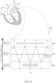
- Figure 4 illustrates a graph 300 showing left atrial pressure ranges including a normal range 301 of left atrial pressure that is not generally associated with substantial risk of postoperative atrial fibrillation, acute kidney injury, myocardial injury, heart failure and/or other health conditions.
- Embodiments of the present disclosure provide systems, devices, and methods for determining whether a patient's left atrial pressure is within the normal range 301, above the normal range 303, or below the normal range 302. For detected left atrial pressure above the normal range, which may be correlated with an increased risk of heart failure, embodiments of the present disclosure as described in detail below can inform efforts to reduce the left atrial pressure until it is brought within the normal range 301.
- embodiments of the present disclosure as described in detail below can serve to facilitate efforts to increase the left atrial pressure to bring the pressure level within the normal range 301.
- Embodiments of the present disclosure provide systems, devices, and methods for determining and/or monitoring fluid pressure and/or other physiological parameters or conditions in the left atrium using one or more implantable sensor devices, such as permanently implanted sensor devices.
- implantable sensor devices such as permanently implanted sensor devices.
- embodiments of the present disclosure can advantageously allow physicians and/or technicians to gather real-time cardiac information, including left atrial pressure values and/or other valuable cardiac parameters.
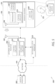
- FIG. 5 illustrates a system 500 for monitoring pressure and/or other parameter(s) in accordance with embodiments of the present disclosure.
- the monitoring system 500 can comprise at least two subsystems, including an implantable internal subsystem or device 510 that includes the sensor transducer(s) 512 (e.g., MEMS pressure sensor(s)), as well as control circuitry 514 comprising one or more microcontroller(s), discrete electronic component(s), and one or more power and/or data transmitter(s) 518 (e.g., antennae coil).
- the monitoring system 500 can further include an external (e.g., non-implantable) subsystem that includes an external reader 550 (e.g., coil), which may include a wireless transceiver that is electrically and/or communicatively coupled to certain control circuitry.
- both the internal and external subsystems include a corresponding antenna for wireless communication and/or power delivery through patient tissue disposed therebetween.
- the sensor implant device 510 can be any type of implant device.
- the sensor implant device 510 can comprise anchor structure 520 as described herein.
- the anchor structure 520 can include one or more stent-type anchors for anchoring in one or more pulmonary veins, as described in greater detail below.
- the anchor structure can further comprise one or more arm/bridge structures that physically couple the sensor housing 516 to one or more stents or other tissue and/or vessel anchors.
- FIG. 5 certain components are illustrated in Figure 5 as part of the sensor implant device 510, it should be understood that the sensor implant device 510 may only comprise a subset of the illustrated components/modules and can comprise additional components/modules not illustrated.
- the sensor implant device 510 includes one or more sensor transducers 512, which can be configured to provide a response indicative of one or more physiological parameters of the patient 515, such as atrial pressure and/or volume.
- sensor transducer(s) 512 can comprise any suitable or desirable types of sensor transducer(s) for providing signals relating to physiological parameters or conditions associated with the sensor implant device 510.
- the sensor transducer(s) 512 can comprise one or more MEMS sensors, optical sensors, piezoelectric sensors, electromagnetic sensors, strain sensors/gauges, accelerometers, gyroscopes, and/or other types of sensors, which can be positioned in the patient 515 to sense one or more parameters relevant to the health of the patient.
- the transducer 512 may be a force-collector-type pressure sensor.
- the transducer 512 comprises a diaphragm, piston, bourdon tube, bellows, or other strain- or deflection-measuring component(s) to measure strain or deflection applied over an area/surface thereof.
- the transducer 512 may be associated with a sensor housing 516, such that at least a portion thereof is contained within, or attached to, the housing 516.
- the term "associated with” is used herein according to its broad and ordinary meaning. With respect to sensor devices/components being “associated with” an anchor or other implant structure, such terminology may refer to a sensor device or component being physically coupled, attached, or connected to, or integrated with, the anchor or other implant structure.
- the transducer 512 comprises or is a component of a piezoresistive strain gauge, which may be configured to use a bonded or formed strain gauge to detect strain due to applied pressure, wherein resistance increases as pressure deforms the component/material.
- the transducer 512 may incorporate any type of material, including but not limited to silicon (e.g., monocrystalline), polysilicon thin film, bonded metal foil, thick film, silicon-on-sapphire, sputtered thin film, and/or the like.
- the transducer 512 comprises or is a component of a capacitive pressure sensor including a diaphragm and pressure cavity configured to form a variable capacitor to detect strain due to pressure applied to the diaphragm.
- the capacitance of the capacitive pressure sensor may generally decrease as pressure deforms the diaphragm.
- the diaphragm may comprise any material(s), including but not limited to metal, ceramic, silicon or other semiconductor, and the like.
- the transducer 512 comprises or is a component of an electromagnetic pressure sensor, which may be configured to measures the displacement of a diaphragm by means of changes in inductance, linear variable displacement transducer (LVDT) functionality, Hall Effect, or eddy current sensing.
- LVDT linear variable displacement transducer
- the transducer 512 comprises or is a component of a piezoelectric strain sensor.
- a piezoelectric strain sensor may determine strain (e.g., pressure) on a sensing mechanism based on the piezoelectric effect in certain materials, such as quartz.
- the transducer 512 comprises or is a component of a strain gauge.
- a strain gauge embodiment may comprise a pressure sensitive element on or associated with an exposed surface of the transducer 512.
- a metal strain gauge is adhered to the sensor surface, or a thin-film gauge may be applied on the sensor by sputtering or other technique.
- the measuring element or mechanism may comprise a diaphragm or metal foil.
- the transducer 512 may comprise any other type of sensor or pressure sensor, such as optical, potentiometric, resonant, thermal, ionization, or other types of strain or pressure sensors.
- the sensor transducer(s) 512 can be configured to generate electrical signals that can be wirelessly transmitted to a device outside the patient's body, such as the illustrated local external monitor system 550.
- the sensor implant device 510 can include radio frequency (RF) transmission circuitry, such as a signal processing circuitry and an antenna 518.
- the antenna 518 can comprise an internal antenna coil or other structure implanted within the patient.
- the control circuitry 514 may comprise any type of transducer circuitry configured to transmit an electromagnetic signal, wherein the signal can be radiated by the antenna 518, which may comprise one or more conductive wires, coils, plates, or the like.
- the control circuitry 514 of the sensor implant device 510 can comprise, for example, one or more chips or dies configured to perform some amount of processing on signals generated and/or transmitted using the device 510. However, due to size, cost, and/or other constraints, the sensor implant device 510 may not include independent processing capability in some embodiments.
- the wireless signals generated by the sensor implant device 510 can be received by the local external monitor device or subsystem 550, which can include a transceiver module 553 configured to receive the wireless signal transmissions from the sensor implant device 510, which is disposed at least partially within the patient 515.
- the external local monitor 550 can receive the wireless signal transmissions and/or provide wireless power using an external antenna 555, such as a wand device.
- the transceiver 553 can include radio-frequency (RF) front-end circuitry configured to receive and amplify the signals from the sensor implant device 510, wherein such circuitry can include one or more filters (e.g., band-pass filters), amplifiers (e.g., low-noise amplifiers), analog-to-digital converters (ADC) and/or digital control interface circuitry, phase-locked loop (PLL) circuitry, signal mixers, or the like.
- RF radio-frequency
- the transceiver 553 can further be configured to transmit signals over a network 575 to a remote monitor subsystem or device 560.
- the RF circuitry of the transceiver 553 can further include one or more of digital-to-analog converter (DAC) circuitry, power amplifiers, low-pass filters, antenna switch modules, antennas or the like for treatment/processing of transmitted signals over the network 575 and/or for receiving signals from the sensor implant device 510.
- the local monitor 550 includes control circuitry 551 for performing processing of the signals received from the sensor implant device 510.
- the local monitor 550 can be configured to communicate with the network 575 according to a known network protocol, such as Ethernet, Wi-Fi, or the like.
- the local monitor 550 is a smartphone, laptop computer, or other mobile computing device, or any other type of computing device.
- the sensor implant device 510 includes some amount of volatile and/or non-volatile data storage.
- data storage can comprise solid-state memory utilizing an array of floating-gate transistors, or the like.
- the control circuitry 514 may utilize data storage for storing sensed data collected over a period of time, wherein the stored data can be transmitted periodically to the local monitor 550 or another external subsystem.
- the sensor implant device 510 does not include any data storage.
- the control circuitry 514 is configured to facilitate wireless transmission of data generated by the sensor transducer(s) 512, or other data associated therewith.
- the control circuitry 514 may further be configured to receive input from one or more external subsystems, such as from the local monitor 550, or from a remote monitor 560 over, for example, the network 575.
- the sensor implant device 510 may be configured to receive signals that at least partially control the operation of the sensor implant device 510, such as by activating/deactivating one or more components or sensors, or otherwise affecting operation or performance of the sensor implant device 510.
- the one or more components of the sensor implant device 510 can be powered by one or more power sources 540. Due to size, cost and/or electrical complexity concerns, it may be desirable for the power source 540 to be relatively minimalistic in nature. For example, high-power driving voltages and/or currents in the sensor implant device 510 may adversely affect or interfere with operation of the heart or other anatomy associated with the implant device.
- the power source 540 is at least partially passive in nature, such that power can be received from an external source wirelessly by passive circuitry of the sensor implant device 510. Examples of wireless power transmission technologies that may be implemented include but are not limited to short-range or near-field wireless power transmission, or other electromagnetic coupling mechanism(s).
- the local monitor 550 may serve as an initiator that actively generates an RF field that can provide power to the sensor implant device 510, thereby allowing the power circuitry of the implant device to take a relatively simple form factor.
- the power source 540 can be configured to harvest energy from environmental sources, such as fluid flow, motion, pressure, or the like. Additionally or alternatively, the power source 540 can comprise a battery, which can advantageously be configured to provide enough power as needed over the relevant monitoring period.
- the remote monitor subsystem 560 can be any type of computing device or collection of computing devices configured to receive, process and/or present monitor data received over the network 575 from the local monitor device 550, secondary local monitor 570, and/or sensor implant device 510.
- the remote monitor subsystem 560 can advantageously be operated and/or controlled by a healthcare entity, such as a hospital, doctor, or other care entity associated with the patient 515.
- the sensor implant device 510 may be implanted in any location in the body the patient 515.
- the sensor implant device 510 is advantageously implanted in the heart of the patient 515, such as in or near the left atrium of the heart, as described in detail herein. Placement of the sensor implant device 510 at least partially within the left atrium can advantageously provide a desirable location for measuring and/or monitoring left atrial pressure, blood viscosity, temperature, and/or other cardiac crammer(s).
- Sensor implant devices in accordance with one or more embodiments of the present disclosure may be implanted using transcatheter procedures, or any other percutaneous procedures. Alternatively, sensor implant devices in accordance with aspects of the present disclosure may be placed during open-heart surgery (e.g., sternotomy), mini-sternotomy, and/or other surgical operation.
- the diagram of Figure 6 shows the sensor implant device 610 implanted at least partially within the left atrium 2, such that a sensor component 616 thereof may advantageously be positioned and/or disposed to determine or acquire sensor signals indicative of one or more physiological parameters associated with the sensor device 610 and/or left atrium 2.
- the sensor implant device 610 may advantageously be anchored to one or more anatomical features/locations associated with the left atrium 2.
- the sensor implant device 610 may comprise one or more anchors and/or other features configured to be anchored at, in, or near one or more of the left 26 and/or right 23 pulmonary veins.
- the sensor component 616 which may advantageously comprise or be associated with a sensor transducer/element 612, at least partially exposed within the left atrium 2, the sensor component 616 may be able to measure various cardiac parameter(s), including but not limited to left atrial pressure, blood viscosity, temperature, and/or others.
- the sensor implant device 610 comprises a first anchor 622, which may be a stent-type anchor configured to be expanded to provide a friction fit with in the ostium and/or vessel associated with a first pulmonary vein, as shown.
- the sensor implant device 610 can further comprise a second anchor 624, which may be configured and/or designed to be implanted to/in an ostium or vessel associated with a second pulmonary vein, as shown.
- the anchor 624 may comprise a stent-type anchor, or a barb-type or other type of anchor configured to be embedded at least partially within biological tissue at or near a target implantation location.
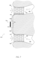
- the sensor module 716 may be anchored order implanted/secured in any suitable or desirable way or manner.
- sensor elements are physically and mechanically coupled to one or more anchor devices by one or more arm or bridge features 730.
- the illustrated implant device 710 includes a first arm member portion 731, as well as a second arm or member portion 733, each of which may be coupled to a respective anchor device, as shown.
- the arm member portions 731, 733 are part of a single unitary form or structure. That is, the sensor module 716 may advantageously be mechanically or physically coupled to a bridge structure 730, wherein portions of such bridge structure on respective sides of the sensor module 716 are called-out in Figure 7 as arm member portions 731, 733, respectively.
- the vessel 701 may represent a first pulmonary vein, whereas the vessel 702 may represent a second pulmonary vein.
- a first anchor device associated with a sensor implant device may be implanted or anchored to a pulmonary vein, whereas a second anchor device associated with the sensor implant device may be implanted or anchored in another manner/configuration, such as by embedding into tissue, or the like.
- stent-type anchor device any types/configurations of anchor devices may be implemented in accordance with embodiments of the present disclosure.
- other expansive anchor forms or devices may be implemented, such as pre-shaped wireforms, struts, clips, and/or other anchor device(s).
- the use of stent-type anchors, as described in detail herein, can advantageously allow for blood flow to flow within the pulmonary vein(s) through the anchor(s) into the left atrium, such that the functionality/flow of the pulmonary vein(s) is not substantially impacted or obstructed.
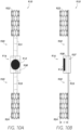
- Figures 10A and 10B illustrate front and side views, respectively, of the sensor implant device 910 shown in Figures 9A and 9B , wherein one or more components of the sensor implant device 910 are configured in a collapsed or crimped state, which may be implemented in order to facilitate delivery of the implant device 910 using a catheter-based delivery system, as described in greater detail below.
- the embodiments shown in Figures 10A and 10B show stent-type anchor devices 922, 924 in an at least partially collapsed/crimped state.
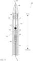
- Figure 11 shows a partial cross-sectional view of a delivery system 100 for a sensor implant device 110 in accordance with one or more embodiments of the present disclosure.
- the delivery system 100 comprises one or more catheters or sheaths used to advance and/or implant the sensor implant device 110, which may be disposed at least partially within the delivery system 100 during a delivery process associated therewith.
- the implant sensor device 110 can be positioned within the delivery system 100 with a first end thereof (i.e., distal anchor 122) disposed distally with respect to the sensor module 116, whereas a second/proximal anchor 124 is positioned at least partially proximately with respect to the sensor module 116.
- the distal 122 and proximal 124 anchor devices may be coupled to the sensor module 116 via one of the securing arm portions 131, 133, respectively.
- the delivery system 100 may further be configured to have a guidewire 150 disposed at least partially within the delivery system 100 and/or coupled thereto in a manner to allow the delivery system 100 to follow a path defined by the guidewire 150.
- the distal anchor device 122 may be contained and/or secured by the outer shaft 140, as illustrated in Figure 11 .
- the proximal portion 133 of the bridge/arm structure 130 and the proximal anchor device 124 may be contained at least partially within the proximal inner shaft 144.
- the proximal anchor pusher support 146 may be disposed and/or contained at least partially within one or more of the outer shaft 140, distal inner shaft 142 and/or proximal inner shaft 144, and further may have disposed in a lumen thereof one or more components of the sensor implant device 110 and/or delivery system 100 during various periods of an associated implantation procedure.
- the guidewire 150 may be disposed at least partially within the proximal anchor pusher support 146 during one or more portions of a medical procedure for implanting the sensor implant device 110.
- the delivery system 100 may be configured to be advanced axially along the guidewire 150 during a medical procedure, wherein the guidewire 150 may be initially placed along a path to a target implantation site, such that the delivery system can be passed over the guidewire 150.
- the guidewire 150 may be disposed within the proximal anchor pusher support (and/or proximal inner shaft 144, distal inner shaft 142, and/or outer shaft 140).
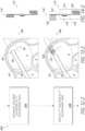
- Figure 12 is a flow diagram illustrating a process 200 for implanting a sensor implant device at or in target anatomy of a patient, such as within one or more cardiac chambers or vessels of a heart of the patient.
- Figure 13 illustrates images of cardiac anatomy, as well as delivery system and sensor implant device components, corresponding to the various operations described in the flow diagram of Figure 12 .
- Figure 13 shows embodiments of a delivery system and sensor implant device that may represent example embodiments of the delivery system 100 and sensor implant device 110 shown in Figure 11 and described in detail above, and therefore similar reference numbers are used for convenience.
- Figure 14 illustrates front and side views, respectively, of the sensor implant device 110 in various configurations corresponding to the respective operations of the process 200 of Figure 12 .
- the process 200 relates to one or more medical procedures for implanting the sensor implant device 110 at least partially within the left atrium 2 of the patient's heart using a suitable delivery system 100.
- the process 200 may be performed in connection with a mitral valve replacements or repair procedure, or another surgical or transcatheter medical procedure requiring access to the left atrium. Therefore, although certain procedure(s) are described for accessing the left atrium, it should be understood that left atrial access by a delivery system in accordance with embodiments of the present disclosure may be made in any suitable or desirable way. For example, such access may be made using a minimally invasive procedure or using a surgical procedure incorporating access to the heart through the chest wall, such as in accordance with an openchest procedure.
- the process 200 involves advancing the delivery system/catheter 100 to the right atrium 5 of the patient's heart using a percutaneous/transcatheter access path or procedure.
- access to the right atrium 5 may be made via the superior 19 or inferior 16 vena cavae, wherein access to the venous system may be made from the subclavian vein, femoral vein, or any other venous (or arterial) blood vessel.
- the sensor implant device 110 may be in an at least partially collapsed/crimped configuration within the delivery system 100 when the delivery system 100 is advanced to the right atrium 5.
- one or more of the distal 122 and/or proximal 124 anchor devices may be axially folded inward towards an axial center of the sensor implant device 110, as shown in image 111 with respect to the proximal anchor 124.
- the process 200 involves advancing the delivery system 100 through the inter-atrial septum 18 separating the right atrium 5 from the left atrium 2, such that the delivery system may pass into the left atrium 2, as shown in image 102 of Figure 13 .
- access to left atrium 2 may be made via other access routes, whereas image 102 shows a particular access route for purposes of explanation and simplicity.
- the operational block 204 may be performed with the sensor implant device 110 maintained in the at least partially compressed configuration shown in image 113.
- the process 200 involves advancing the delivery system 100 to, within, and/or in proximity to a pulmonary vein 26 that is fluidly coupled with the left atrium 2, as described in detail above.
- a pulmonary vein 26 that is fluidly coupled with the left atrium 2, as described in detail above.
- the image 103 shows the delivery system 100 advanced to the left superior pulmonary vein 26, it should be understood that such vein is represented in image 103 for descriptive purposes only, and any other pulmonary vein or other chamber or vessel may be engaged by the delivery system 100 in accordance with embodiments of the present disclosure.
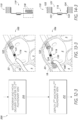
- the process 200 involves deploying a distal anchor device 122 of the sensor implant device 110 in and/or to the target pulmonary vein 26 and/or tissue associated therewith.
- the operation associated with block 208 may involve expanding the tissue anchor device 122 within a conduit/lumen of the pulmonary vein 26.
- alternative anchoring mechanisms or techniques may be implemented, such as anchoring tissue-embedding anchor device(s) into the interior of the pulmonary vein conduit, or to left atrial tissue proximate to the pulmonary vein 26 and/or ostium thereof.
- the distal anchor device 122 may be coupled or associated with an arm member/portion 131, which may be at least partially deployed from the delivery system 100 in connection with the operation associated with block 208 (and/or the operation associated with block 210, described below).
- the arm member/portion 131 may be at least partially bent or configured to accommodate the distal anchor device 122, such that the remainder of the sensor implant device 110 may be oriented at a generally-orthogonal/perpendicular orientation with respect to the axis of the distal anchor device 122, as shown in the accompanying image 117 of Figure 14 .
- a portion 114 of the sensor implant device 110 may remain and/or be maintained within the delivery system 100 after deployment of the distal anchor device 122.
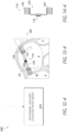
- the process 200 involves withdrawing the delivery system 100 an axial distance away from the pulmonary vein 26 in order to move the delivery system 100 and/or distal end thereof to, within, and/or into proximity with a second target pulmonary vein 23, which may thereby serve to deploy from the delivery system 100 one or more components or portions of the sensor implant device 110, such as one or more portions or components of the bridge/arm structure (e.g., portion 131) and/or sensor module 116, as shown in image 105.
- the portion 118 of the sensor implant device 110 that remains within the delivery system may include the proximal anchor device 124 and/or one or more portions 133 of the bridge/arm structure of the sensor implant device 110. That is, the sensor implant device 110 may be in a position/configuration in which the sensor module 116 is deployed from the delivery system 100 at a stage associated with the operation of block 210.
- the arm portion 133 coupling the proximal tissue anchor 124 to the remaining structure of the sensor implant device 110 may be unbent, or otherwise oriented or bent in order to allow for the anchor device 124 to be substantially coaxial with the pulmonary vein 23, while allowing the remainder of the bridge structure 130 of the sensor implant device 110 to bridge between the first target pulmonary vein 26 and the second target pulmonary vein 23.
- the second target pulmonary vein 23 is illustrated as corresponding to the right superior pulmonary vein, it should be understood that the second target pulmonary vein may be any suitable or desirable pulmonary vein, as described in detail below relative to Figures 15 , 16 , 17 , and/or 18.
- the process 200 involves withdrawing the delivery catheter from the heart and/or body of the patient, thereby leaving or maintaining the sensor implant device 110 as implanted in and/or otherwise engaged with the target pulmonary veins 26, 23, as described above. Therefore, the sensor implant device 110 may be maintained in a shape or configuration similar to that shown in image 123 of Figure 14 after implantation thereof.
- Figures 6 and 13 illustrated in detail above, illustrate for reference sensor implant devices implanted between a left superior pulmonary vein at a distal end of the sensor implant device and a right superior pulmonary vein at a proximal end of the sensor implant device.
- Figure 8 illustrates a sensor implant device implanted between a left superior pulmonary vein and a left inferior pulmonary vein.
- sensor implant devices in accordance with embodiments of the present disclosure may be implanted between any two of the pulmonary veins (or other blood vessel), and/or may be implanted and/or secured to only a single pulmonary vein, or to three or more pulmonary veins.
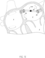
- Figure 15 illustrates a left atrium 2 and associated anatomy, including pulmonary veins, wherein a sensor implant device 310 is implanted between a left inferior pulmonary vein 25 and a right superior pulmonary vein 23.
- a sensor implant device 310 is implanted between a left inferior pulmonary vein 25 and a right superior pulmonary vein 23.
- Either the left inferior pulmonary vein 25 or the right superior pulmonary vein 23 may be considered the distal end or the proximal end of the sensor implant device 310 with respect to an implantation procedure implemented in connection with Figure 15 .
- the implantation orientation of the sensor implant device 310 as in Figure 15 may be implemented in connection with any of the embodiments of the present disclosure, such as an alternative to any other illustrated and/or described orientations associated with the respective embodiments.
- Figure 16 illustrates a left atrium 2 and associated anatomy, including pulmonary veins, wherein a sensor implant device 311 is implanted between a left inferior pulmonary vein 25 and a right inferior pulmonary vein 21.
- a sensor implant device 311 is implanted between a left inferior pulmonary vein 25 and a right inferior pulmonary vein 21.
- Either the left inferior pulmonary vein 25 or the right inferior pulmonary vein 21 may be considered the distal end for the proximal end of the sensor implant device 311 with respect to an implantation procedure implemented in connection with Figure 16 .
- the implantation orientation of the sensor implant device 311 as in Figure 16 may be implemented in connection with any of the embodiments of the present disclosure, such as an alternative to any other illustrated and/or described orientations associated with the respective embodiments.
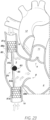
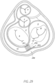
- Figure 18 illustrates a left atrium 2 and associated anatomy, including pulmonary veins, wherein a sensor implant device 313 is implanted between a right inferior pulmonary vein 21 and a right superior pulmonary vein 23.
- a sensor implant device 313 is implanted between a right inferior pulmonary vein 21 and a right superior pulmonary vein 23.
- Either the right inferior pulmonary vein 21 or the right superior pulmonary vein 23 may be considered the distal end or the proximal end of the sensor implant device 313 with respect to an implantation procedure implemented in connection with Figure 18 .
- the implantation orientation of the sensor implant device 313 as in Figure 18 may be implemented in connection with any of the embodiments of the present disclosure, such as an alternative to any other illustrated and/or described orientations associated with the respective embodiments.
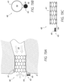
- FIG 19A shows a side deployed view of a sensor implant device 40 anchored in a blood vessel 35 in accordance with one or more embodiments.
- Figure 19B shows an axial view of the sensor implant device 40 of Figure 19A in accordance with one or more embodiments.
- Figure 19C shows a side view of the sensor implant device 40 of Figure 19A in accordance with one or more embodiments.
- the sensor implant device 40 shown in Figures 19A-19C includes a single stent anchor 41, wherein a sensor device 43 is physically coupled thereto in some manner.
- a support arm 44 may be attached to and/or integrated with the stent frame 41 and may mechanically couple the sensor device 43 to the anchor frame 41.
- the sensor device 43 may extend axially from an end of the anchor frame 41, and possibly into a chamber or blood vessel into which the blood vessel 35 opens, wherein constituents of blood or other fluid present in such chamber/vessel are sensed by the sensor device 43, such as blood/fluid pressure or the like.
- the anchor 41 may be anchored within a cardiac blood vessel, such as within a pulmonary vein and/or ostium thereof, as described in detail herein.
- the sensor device 43 may be exposed to blood/fluid within the left atrium, benefits of which are described above in detail.
- sensor support arm/strut features of such embodiments may comprise separate bar-type features that are fixed to the respective stent anchors (or other types of anchors), or they may be integrated with the frames/forms of the respective anchors. It should be understood that any of the features of the sensor implant devices disclosed in connection with Figures 6-18 may be implemented in any of the sensor implant devices disclosed in connection with Figures 19--31, and any of the features of the sensor implant devices disclosed in connection with Figures 19-31 may be implemented in any of the sensor implant devices disclosed in connection with Figures 6-18 .
- the sensor device 43 and/or support arm 44 may be deflected radially outward with respect to the axis of the anchor frame 41, such that the sensor device 43 is substantially parallel to the tissue wall 31 (e.g., interior left atrium wall) outside of the anchoring vessel 35, or at an acute angle with respect to the tissue wall 31.
- Outward deflection of the sensor device 43 and/or support arm 44 may be achieved through manual bending of the support arm 44, or through autonomous movement/deflection of the sensor-support arm 44 caused by shape-memory characteristics/features of the arm 44.
- the sensor-support arm 44 may be integrally formed with the anchor frame 41.
- the support arm 44 may extend from one or more strut or extension features of the support frame 41.
- Such features may be laser-cut from a metal sheet/form to form an expandable stent frame and sensor-support arm/extension extending from the frame as an integral extension/feature thereof.
- Figure 19B shows an axial view of the sensor implant device 40, wherein the sensor device 43 and/or the sensor-support arm 44 are deflected radially outward.
- the sensor transducer element/portion 45 of the sensor device 43 may be exposed outward (i.e., facing out of the page with respect to the illustrated orientation of Figure 19B ).
- readings of the sensor device 43 may be less directly tied to the flow through the barrel 46, and rather may be indicative of parameters of the blood in the chamber into which the vessel 35 opens.
- the sensor device 43 may be attached or coupled to the support arm/strut 44 in any suitable or desirable way.
- the sensor device 43 may be secured to the support arm 44 using an adhesive, or other means.
- a mechanical coupling is implemented between sensor device 43 and the arm 44.
- the sensor device 43 may sit within a recess or other feature configured to engage the sensor housing around at least a portion of a circumference thereof.
- the support arm 44 may include a hook, clasp, clip, or other locking/engagement feature configured to engage with an aperture or other opening feature of the sensor housing, or vice versa.
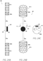
- Figure 20A shows a side deployed view of a sensor implant device 50 anchored in a blood vessel 35, such as a pulmonary vein and/or pulmonary vein ostium, in accordance with one or more embodiments.
- Figure 20B shows an axial view of the sensor implant device 50 of Figure 20A in accordance with one or more embodiments.
- Figure 20C shows a side view of the sensor implant device 50 of Figure 20A in a delivery configuration in accordance with one or more embodiments.
- Figures 19A-19C which illustrates a sensor implant device 40 including a sensor 43 supported by an arm/strut feature 44, which extends axially from an end of the stent anchor frame 41
- the embodiments of the sensor implant device 50 shown in Figures 20A-20C include a sensor device 53 that is secured to the anchor frame 51 through direct attachment to the inner diameter thereof. That is, the sensor device 53 may be embedded and/or secured in some manner in/to the stent frame 51 without the need/use of an axially extending support arm/strut.
- the sensor transducer feature/element 55 may be generally exposed within the inner barrel 56 of the device 50. Therefore, with the anchor frame 51 anchored within a blood vessel 35, such as a pulmonary vein, the sensor transducer 55 may be configured to sense characteristics of blood flow through the blood vessel 35 and stent frame 51. In some cases, the fluid pressure within the pulmonary vein or other blood vessel 35 may be different than that in the chamber (e.g., left atrium) outside of the blood vessel 35. Therefore, this position of the sensor device 53 within the inner diameter of the stent frame 51 may allow for sensing of fluid characteristics that may be different from corresponding characteristics of fluid present outside of the blood vessel 35, such as flow, pressure, and/or other sensed characteristics.
- the sensor device 53 may be attached to the frame 51 at or near a distal end of the frame 51 (i.e., on a left side of the frame 51 in the illustrated orientation of Figure 20A ).
- the sensor device 53 may be secured to the inner diameter of the frame 51 through adhesive, welding, and/or other permanent or temporary fixation means.
- the housing of the sensor 53 may be configured to be snapped, hooked, clipped, clasped, and/or otherwise engaged with the frame 51, such as within one or more cells of the frame lattice, to provide a mechanical attachment/locking connection between the sensor 53 (and/or sensor housing) and the frame.
- the sensor device 53 may be configured to fit within the barrel 56 of the device 50, wherein the sensor transducer element/feature 55 of the sensor device 53 generally faces radially inward.
- the sensor transducer 55 may be generally axially oriented, such that the face thereof faces with or opposing the flow of fluid through the barrel 56.
- Figure 20C shows the sensor implant device 50 in a compressed delivery configuration.
- the anchor frame 51 may be radially crimped/compressed to allow for a smaller diametrical profile for disposing within a delivery catheter or other delivery device.
- the sensor device 53 may advantageously be small enough such that radial crimping of the anchor frame 51 is not impeded by the presence of the sensor device 53 within the barrel 56 of the anchor frame 51.
- Figure 21A shows a side deployed view of a sensor implant device 60 anchored in a blood vessel 35 in accordance with one or more embodiments.
- Figure 21B shows an axial view of the sensor implant device 60 of Figure 21A in accordance with one or more embodiments.
- Figure 21C shows a side view of the sensor implant device 60 of Figure 21A in a delivery configuration in accordance with one or more embodiments.
- the sensor implant device 60 illustrated in Figures 21A-21C is similar in various respects to the sensor implant device 40 shown in Figures 19A-19C and described above. However, unlike the sensor implant device 40 shown in Figure 19A , the sensor implant device 60, shown in Figure 21A in a deployed configuration, may not be radially deflected when deployed.
- the sensor-support arm/strut 64 may extend axially from an end of the stent frame 61 (i.e., left-most end of the frame 61 in the illustrated orientation of Figure 21A ) in a generally straight configuration.
- the sensor transducer 65 may generally face radially inward with respect to the axis of the anchor frame 61. However, it should be understood that in some embodiments, the sensor transducer 65 may face radially outward and/or axially distally or proximally with respect to the orientation of the anchor frame 61.
- the radially-inward-facing orientation of the sensor device 63 and/or sensor transducer 65 is demonstrated, wherein the sensor transducer 65 lies within the radius of the barrel 56 of the frame 61, albeit in a position that is axially extended beyond the end of the frame 61.
- the sensor device 63 may be supported by a generally straight support strut/arm 64 during delivery thereof.
- Figure 22A shows a side deployed view of a sensor implant device 70 anchored in a blood vessel 35 in accordance with one or more embodiments.
- Figure 22B shows an axial view of the sensor implant device 70 of Figure 22A in accordance with one or more embodiments.
- Figure 22C shows a side view of the sensor implant device 70 of Figure 22A in a delivery configuration in accordance with one or more embodiments.
- the sensor device 73 is supported by a plurality of support arms 74a, 74b.
- the sensor device 73 may be held at or near an axial center of the barrel 76 of the anchor frame 71, which may be deployed/implanted within a blood vessel 35, such as a pulmonary vein.
- the arms 74a, 74b may hold the sensor device 73 in a position axially beyond the end 78 of the anchor frame 71 (i.e., the leftmost end of the frame 71 with respect to the illustrated orientation of Figure 22A ), such that the sensor device 73 is disposed some distance the in front of (i.e., to the left of with respect to Figure 22A ) the anchor frame 71 and/or ostium of the blood vessel 35.
- the support arms/struts 74a, 74b hold the sensor device 73 within the axial bounds of the support frame 71. That is, unlike the illustrated implementation shown in Figure 22A , in some embodiments, the sensor device 73 may be held axially within the anchor frame 71.
- Figure 22B shows the sensor device 73 held by the support arms 74a, 74b within the radius of the barrel 76 of the anchor frame 71, albeit axially beyond the end of the frame 71.
- the sensor device 73 may include one or more sensor transducer features/elements 75, 77.
- the sensor transducer 77 is shown as facing against of the flow of fluid through the anchor frame 71, and therefore may be configured and/or disposed in a position to sense parameters associated with such fluid flow incident on the fate of the transducer 77.
- the sensor device 73 includes a sensor transducer 75 facing axially outward with respect to the orientation of the anchor frame 71.
- the sensor 73 may be configured to sense parameters of the fluid within the chamber (e.g., left atrium) outside of the blood vessel 35 that is less affected by the flow through the anchor frame 71 than with respect to sensor transducers facing axially inward, as with the illustrated transducer 77.
- the sensor transducers may be implemented in connection with the embodiments of Figures 22A-22C .
- the arms 74a, 74b may attached to the housing/structure of the sensor 73 in any suitable or desirable manner.
- the arms are configured to hook or otherwise engage into/with eyelet/aperture features of the sensor housing to create a mechanical coupling therewith.
- the arms 74a, 74b form or are associated/integrated with a circumferential sensor-retention band or cup feature in which the sensor device 73 may be disposed/secured.
- the sensor device 73 may be secured to the arms 74a, 74b and/or associated sensor-retention features thereof through tension fit or other mechanical attachment mechanism.
- the support arms 74a, 74b may assume a bent configuration, wherein such bends are at sharper angles than the bends of the arms 74a, 74b in the deployed configuration shown in Figure 22A .
- the sensor device 73 may be already coupled to the support arms 74a, 74b, such that in deployment, no attachment of the sensor device 73 to the support arms 74a, 74b is necessary.
- FIG 23 shows a sensor implant device 80 implanted in the superior and inferior vena cavae in accordance with one or more embodiments.
- the sensor implant device 80 includes a sensor 83 coupled to one or more stent-like anchors 81a, 81b configured to be anchored within the superior 19 and inferior 16 vena cava, respectively.
- the sensor 83 may be coupled to the stent anchors via one or more arms/connectors 84.
- the first arm portion 84a may physically extend between the sensor 83 and the stent anchor 81a
- the arm portion 84b may extend between the sensor 83 and the stent anchor 81b.
- the arm(s) 84 may comprise a single bar extending between the stent anchor 81a and the stent anchor 81b, wherein the sensor 83 is secured in some manner to the bar 84.
- the portions 84a, 84b represent physically separate arm segments extending from the sensor 83.
- the sensor 83 may be coupled to the arm(s) 84 in any suitable or desirable manner, such as through the use of one or more adhesives, clips, fittings, and/or other coupling features.
- the sensor 83 may generally be disposed and exposed within the right atrium 5 of the heart.
- a sensor such as a pressure sensor
- CBP central venous pressure
- one or more of the anchors 31 may include certain valve features 88.
- such valve features may be one-way valves, which may allow fluid flow into the right atrium from the inferior and/or superior vena cavae, while impeding our preventing blood flow from the right atrium 5 into the superior 19 and/or inferior vena cavae.
- one or more anchors 81 include one-way valves allowing outflow into the right atrium, such valve(s) can prevent or reduce backflow into the veins, thereby reducing the risk and/or occurrence of edema, swelling, and/or other medical conditions.
- valved stent anchors may be implanted/disposed within the vena cava without an associated/coupled sensor device. That is, the anchors may be used for the purpose of preventing backflow of blood into the veins, with or without associated sensor functionality/feature(s).
- any physical coupling 84 between the anchors 81 that may be present may be used as a docking structure for any type of implant device.
- the coupling arm 84 may be used for docking one or more additional implant devices or components, such as spacer devices, replacement valves, or the like.
- a replacement valve device such as a replacement tricuspid valve, may be implanted within the annulus of the tricuspid valve 8 and further secured or docked to the arm structure 84 and/or one or more of the blood vessel anchors 81.
- a tricuspid valve spacer device may be anchored to the coupling arm 84 and/or one or more of the stent anchors 81.
- the optional valve features 88 may comprise 2, 3, or other number of leaflets, which may be formed of biological and/or synthetic material(s).
- the sensor implant device 80 may be implanted in any suitable or desirable manner.
- implanting the sensor implant device 80 may involve advancing a delivery system, which may include one or more delivery catheters, into to a first vena cava of the patient, either the superior vena cava 19 or the inferior vena cava 16, via a transcatheter access path, as shown and described in connection with Figure 32 .
- the method may further involve advancing the delivery system through at least a portion of a right atrium 5 of the patient and into a second vena cava of the patient (i.e., the other of the superior vena cava 19 and the inferior vena cava 16), deploying a distal anchor (i.e., a first one of the anchors 81a, 81b, depending on which of the vena cavae the anchor is being deployed in) of a sensor implant device from the delivery system, anchoring the distal anchor of the sensor implant device within the second vena cava.
- a distal anchor i.e., a first one of the anchors 81a, 81b, depending on which of the vena cavae the anchor is being deployed in
- the delivery system may then be withdrawn through the at least a portion of the right atrium 5, thereby exposing at least a portion of the sensor device 83 of the sensor implant device, as well as a first support arm portion (i.e., either 84a or 84b, or both) coupling the sensor device to the distal anchor, in the right atrium 5.
- the process may further involve deploying a proximal anchor of the sensor implant device (i.e., a second one of the anchors 81a, 81b, depending on which of the vena cavae the anchor is being deployed in) from the delivery system within the first vena cava, and anchoring the proximal anchor of the sensor implant device to within the first vena cava.
- the delivery system may then be withdrawn from the patient.
- Figures 24A-C show crimped side, expanded front, and axial views, respectively, of a sensor implant device in accordance with one or more embodiments.
- Figure 24A shows the cardiac implant device 80 of Figure 23 in an at least partially crimped/compressed delivery configuration.
- the one or more stent anchors 81 may be radially compressed such that a cross-sectional profile thereof is sufficiently small to fit within the delivery catheter or other delivery device or system component.
- the coupling arm segments 84 may have any suitable or desirable length.
- Figure 24B shows a front view of the device 80, wherein the sensor transducer 85 is shown.
- the sensor implant device 80 is in a deployment configuration, wherein the stent anchors 81 are at least partially expanded for contact with respective blood vessel walls of the superior and inferior vena cavae.
- the images of Figures 24A and 24B show the optional valve features 88a and 88b associated with the anchors 81a and 81b, respectively.
- the illustrated embodiment includes one or more 3-leaflet valves.
- valve features associated with anchors disclosed herein have any number of leaflets and/or other valve component or features.
- Figure 24C shows an axial view of the device 80 showing the sensor 83 and the valve feature 88b.
- the sensor transducer 85 may be disposed within and/or facing radially inward with respect to the radius/diameter of the anchor 81. Therefore, blood flow through the anchor valve 88 may be directed generally in the direction of the sensor device 53, some of which may pass over the sensor transducer 85.
- Figure 25 shows a sensor implant device 90 anchored in a superior vena cava 19 in accordance with one or more embodiments.
- the sensor implant device 90 includes a sensor device 93 mechanically coupled to and/or otherwise associated with the inner diameter of the stent anchor 91. That is, the sensor 93 may not be coupled to the anchor 91 by an extended arm feature, as in Figure 23 , but rather may be disposed at least partially within the inner diameter of the stent anchor 91.
- the stent anchor 91 is disposed in the superior vena cava 19 and therefore the sensor 93 may be configured to determine certain parameters associated with blood flow into the right atrium 5 from the superior vena cava 19.
- Figure 26 shows a sensor implant device 96 anchored in an inferior vena cava 16 in accordance with one or more embodiments.
- the sensor implant device 96 includes a sensor device 94 mechanically coupled to and/or otherwise associated with the inner diameter of the stent anchor 92. That is, the sensor 94 may not be coupled to the anchor 92 by an extended arm feature, as in Figure 23 , but rather may be disposed at least partially within the inner diameter of the stent anchor 92.
- the stent anchor 92 is disposed in the inferior vena cava 16 and therefore the sensor 94 may be configured to determine certain parameters associated with blood flow into the right atrium 5 from the inferior vena cava 19.
- Figure 27 shows a sensor implant device 270 anchored in a superior vena cava 19 in accordance with one or more embodiments.
- the sensor implant device 270 includes a sensor device 275 mechanically coupled to a stent anchor 271 via a coupling arm 274, which may be similar in certain respects to any of the other coupling arm features disclosed in connection with various embodiments of the present disclosure.
- the coupling arm 274 may have any suitable or desirable length. For example, the length of the coupling arm 274 may be selected to project the sensor device 273 a desired distance into the right atrium 5.
- the sensor transducer 275 is illustrated as being oriented and/or facing inward with respect to an axis of the anchor 271, as with any other embodiment disclosed herein, it should be understood that the sensor device 273 may have sensor transducer(s) configured and/or oriented in any suitable or desirable way.
- the coupling arm 274 is shown as a generally straight, it should be understood that the arm 274 may have any length, shape, and or configuration. For example, in some embodiments, the arm 274 may be deflected towards a center of the right atrium 5 to thereby provide a more central position for the sensor device 273 with respect to the right atrium 5.
- Figure 28 shows a sensor implant device 280 anchored in an inferior vena cava 16 in accordance with one or more embodiments.
- the sensor implant device 280 includes a sensor 283 mechanically coupled to a stent anchor 281 via a coupling arm 284, which may be similar in certain respects to any of the other coupling arm features disclosed in connection with various embodiments of the present disclosure.
- the coupling arm 284 may have any suitable or desirable length. For example, the length of the coupling arm 284 may be selected to project the sensor device 283 a desired distance into the right atrium 5.
- the sensor transducer 285 is illustrated as being oriented and/or facing inward with respect to an axis of the anchor 281, as with any other embodiment disclosed herein, it should be understood that the sensor device 283 may have sensor transducer(s) configured and/or oriented in any suitable or desirable way.
- the coupling arm 284 is shown as a generally straight, it should be understood that the arm may have any length, shape, and or configuration.
- the arm 284 may be deflected towards a center of the right atrium 5 to thereby provide a more central position for the sensor device 283 with respect to the right atrium 5.
- Figure 29 shows a sensor implant device 290 anchored at least partially within a coronary sinus 16 and/or ostium 14 thereof.
- the sensor implant device 290 includes a sensor device 293, which may be similar in certain respects to various other embodiments disclosed herein.
- the sensor device 293 is coupled to the anchor 291 via a coupling arm 294, as with other embodiments disclosed herein.
- the implant device 290 does not include a sensor and/or sensor coupling arm, but rather includes a valve feature or other feature associated with the stent anchor 291.
- Anchoring of a sensor implant device at least partially within the coronary sinus can allow for placement of an associated sensor within and/or near the right atrium, which may allow for measurement of central venous blood pressure and/or other parameter(s) associated with central venous flow and/or the right atrium.
- sensors associated with implant devices anchored to/in the coronary sinus may be used to sense/determine various hemodynamic parameters, such as central venous pressure, blood viscosity, pulmonary artery pressure, and/or other parameter(s).
- such anchors may be self-expandable or balloon-expandable.
- a delivery catheter may be used to deliver and/or implant the anchor device 291.
- the location of the sensor anchor 291 at or near the coronary sinus ostium 14 can be used for attaching biodegradable or drug-eluding devices and/or may be used as an anchor for various medical device implants, including replacement valve devices, valve spacer devices, and/or the like.
- stent anchors are generally described and illustrated in connection with the present disclosure, it should be understood that such anchors may have any suitable form, shape, and/or configuration.
- other types of anchor features are implemented, including spiral wire anchors, barbs, and/or other types of tissue anchors.
- the sensor coupling arm 294 may have any suitable or desirable length, wherein such length may be designed to project the sensor 293 a desired distance into the right atrium 5 and/or coronary sinus ostium 14.
- Figure 30 shows an example implant device 305, wherein the sensor device 308 associated therewith is coupled to the associated stent anchor 306 via a relatively short coupling strut or arm 309, such that the sensor 308 projects only a short distance past the axial end of the anchor 306.
- the sensor 308 may be merely clipped or secured to a strut feature of one or more cells of the stent 306 without utilizing an extended arm feature extending from the lattice of the stent.
- Figure 31 shows a sensor implant device 320 disposed/deployed within the coronary sinus 16 and/or coronary sinus ostium 14, wherein the device 320 includes a sensor device 323 disposed at least partially within an inner diameter of an anchor 321 of the device 320.
- the sensor device 323 may be secured or attached to one or more cells of a stent-type lattice of the anchor 321 through any type of attachment means, including one or more clips, books, straps, collars, and/or any other type of mechanical and/or tension fit.
- Sensor implant devices in accordance with one or more embodiments of the present disclosure may be advanced to the left atrium using any suitable or desirable procedure.
- access to the left atrium is illustrated and described in connection with certain embodiments as being via the right atrium and/or inferior vena cavae, such as through a transfemoral or other transcatheter procedure, other access paths/methods may be implemented in accordance with embodiments of the present disclosure, as described/shown in connection with Figure 32 .
- Figure 32 illustrates various access paths through which access to the left ventricle may be achieved, including transseptal access 401a, 401b, which may be made through the inferior vena cava 16 or superior vena cava 32, as respectively shown, and from the right atrium 5, through the septal wall (not shown) and into the left atrium 2.
- transaortic access 402 a delivery catheter may be passed through the descending aorta, aortic arch 12, ascending aorta, and aortic valve 7, and into the left atrium 2 through the mitral valve 6.
- transapical access 403 access may be made directly through the apex of the heart into the left ventricle 3, and into the left atrium 2 through the mitral valve 6.
- Other access paths are also possible beyond those shown in Figure 32 .
- indefinite articles may indicate “one or more” rather than “one.”
- an operation performed "based on” a condition or event may also be performed based on one or more other conditions or events not explicitly recited.
Landscapes
- Health & Medical Sciences (AREA)
- Life Sciences & Earth Sciences (AREA)
- Physics & Mathematics (AREA)
- Molecular Biology (AREA)
- Animal Behavior & Ethology (AREA)
- Pathology (AREA)
- Engineering & Computer Science (AREA)
- Biomedical Technology (AREA)
- Heart & Thoracic Surgery (AREA)
- Medical Informatics (AREA)
- Veterinary Medicine (AREA)
- Surgery (AREA)
- Biophysics (AREA)
- General Health & Medical Sciences (AREA)
- Public Health (AREA)
- Cardiology (AREA)
- Vascular Medicine (AREA)
- Physiology (AREA)
- Optics & Photonics (AREA)
- Measuring Pulse, Heart Rate, Blood Pressure Or Blood Flow (AREA)
- Electrotherapy Devices (AREA)
Claims (15)
- Zuführungssystem (100), umfassend:einen äußeren Schaft (140);eine Sensorimplantatvorrichtung (110), die wenigstens teilweise innerhalb des äußeren Schafts angeordnet ist, wobei die Sensorimplantatvorrichtung umfasst:eine erste Ankervorrichtung (122);eine zweite Stent-Ankervorrichtung (124); undein Sensormodul (116), das physisch mit der ersten Ankervorrichtung (122) und der zweiten Ankervorrichtung (124) gekoppelt ist; undeinen distalen inneren Schaft (142), der wenigstens teilweise innerhalb des äußeren Schafts (140) angeordnet und so konfiguriert ist, dass er axial an der ersten Ankervorrichtung (122) innerhalb des äußeren Schafts (140) anliegt, wobeidie erste Ankervorrichtung (122) ohne den distalen inneren Schaft (142) und distal zu dem distalen inneren Schaft angeordnet ist und das Sensormodul (116) wenigstens teilweise innerhalb des distalen inneren Schafts (142) angeordnet ist.
- Zuführungssystem nach Anspruch 1, das ferner einen proximalen inneren Schaft (144) umfasst, der wenigstens teilweise innerhalb des distalen inneren Schafts (142) angeordnet und so konfiguriert ist, dass er axial an dem Sensormodul (116) innerhalb des distalen inneren Schafts anliegt.
- Zuführungssystem nach Anspruch 2, wobei:die zweite Stent-Ankervorrichtung (124) wenigstens teilweise innerhalb des proximalen inneren Schafts (144) angeordnet ist;der proximale innere Schaft (144) einen Durchmesser aufweist, der kleiner ist als ein Durchmesser des distalen inneren Schafts (142);die zweite Stent-Ankervorrichtung (124) innerhalb des proximalen inneren Schafts (144) in einer wenigstens teilweise komprimierten Konfiguration angeordnet ist; unddie zweite Stent-Ankervorrichtung (124) in der zumindest teilweise komprimierten Konfiguration einen Durchmesser aufweist, der kleiner ist als ein Durchmesser der ersten Ankervorrichtung (122), wie sie konfiguriert und innerhalb des äußeren Schafts (140) angeordnet ist.
- Zuführungssystem nach Anspruch 3, wobei die zweite Stent-Ankervorrichtung (124) mit dem Sensormodul (116) über einen Armabschnitt (131) gekoppelt ist, der so gebogen ist, dass ein Endabschnitt der zweiten Stent-Ankervorrichtung (124) innerhalb des proximalen inneren Schafts (144) distal ausgerichtet ist.
- Zuführungssystem nach Anspruch 3 oder 4, das ferner eine Schiebervorrichtung (146) umfasst, die wenigstens teilweise innerhalb des proximalen inneren Schafts (144) angeordnet und so konfiguriert ist, dass sie axial an der zweiten Stent-Ankervorrichtung (124) innerhalb des proximalen inneren Schafts anliegt.
- Zuführungssystem nach Anspruch 5, wobei die Schiebervorrichtung (146) ein zentrales Lumen aufweist, das dazu konfiguriert ist, einen Führungsdraht (150) darin aufzunehmen.
- Zuführungssystem nach einem der Ansprüche 1 bis 6, wobeidie erste Ankervorrichtung (722) der Sensorimplantatvorrichtung (710) eine Stent-Ankervorrichtung ist, die über einen ersten Armstrukturabschnitt (731) mit dem Sensormodul (716) gekoppelt ist;die zweite Stent-Ankervorrichtung (724) über einen zweiten Armstrukturabschnitt (733) mit dem Sensormodul gekoppelt ist; und wobeijede der ersten und der zweiten Stent-Ankervorrichtung selbst-expandierend ist.
- Zuführungssystem nach einem der Ansprüche 1 bis 7, wobei
das Sensorelement (116, 716) dazu konfiguriert ist, ein Signal zu erzeugen, das einen physiologischen Parameter angibt. - Zuführungssystem nach Anspruch 8, wobei der physiologische Parameter ein Fluiddruck ist.
- Zuführungssystem nach Anspruch 7 oder 8, wobei der erste und der zweite Armstrukturabschnitt (731, 733) Teil einer einheitlichen Brückenstruktur (730) sind, die zwischen der ersten Stent-Ankervorrichtung (722) und der zweiten Stent-Ankervorrichtung (724) gekoppelt ist.
- Zuführungssystem nach Anspruch 10, wobei das Sensormodul ein Eingriffsmerkmal aufweist, das dazu konfiguriert ist, mit der Brückenstruktur in Eingriff zu gelangen.
- Zuführungssystem nach Anspruch 11, wobei das Eingriffsmerkmal einer Unterseite eines Gehäuses des Sensormoduls zugeordnet ist.
- Zuführungssystem nach einem der vorangehenden Ansprüche, wobei das Sensormodul (916) ein Kanalmerkmal (938) aufweist, das dazu konfiguriert ist, einen Führungsdraht darin aufzunehmen.
- Zuführungssystem nach einem der vorangehenden Ansprüche, wobei die erste Stent-Ankervorrichtung (922) so dimensioniert ist, dass sie sich in einer ersten Pulmonalvene in einer expandierten Entfaltungskonfiguration verankert, und wobei die zweite Stent-Ankervorrichtung (924) so dimensioniert ist, dass sie sich in einer zweiten Pulmonalvene in einer expandierten Entfaltungskonfiguration verankert.
- Zuführungssystem nach einem der Ansprüche 1 bis 13, wobei der Stentanker (81a, 81b) so dimensioniert ist, dass er sich in wenigstens einer von einer oberen Vena cava (19) oder einer unteren Vena cava (16) in einer expandierten Entfaltungskonfiguration verankert.
Priority Applications (1)
| Application Number | Priority Date | Filing Date | Title |
|---|---|---|---|
| EP25169175.4A EP4623807A3 (de) | 2019-08-22 | 2020-08-12 | Blutgefässverankerter herzsensor |
Applications Claiming Priority (2)
| Application Number | Priority Date | Filing Date | Title |
|---|---|---|---|
| US201962890537P | 2019-08-22 | 2019-08-22 | |
| PCT/US2020/045975 WO2021034573A1 (en) | 2019-08-22 | 2020-08-12 | Blood-vessel-anchored cardiac sensor |
Related Child Applications (1)
| Application Number | Title | Priority Date | Filing Date |
|---|---|---|---|
| EP25169175.4A Division EP4623807A3 (de) | 2019-08-22 | 2020-08-12 | Blutgefässverankerter herzsensor |
Publications (2)
| Publication Number | Publication Date |
|---|---|
| EP4017350A1 EP4017350A1 (de) | 2022-06-29 |
| EP4017350B1 true EP4017350B1 (de) | 2025-04-09 |
Family
ID=72193682
Family Applications (2)
| Application Number | Title | Priority Date | Filing Date |
|---|---|---|---|
| EP20761098.1A Active EP4017350B1 (de) | 2019-08-22 | 2020-08-12 | In blutgefäss verankerter herzsensor |
| EP25169175.4A Pending EP4623807A3 (de) | 2019-08-22 | 2020-08-12 | Blutgefässverankerter herzsensor |
Family Applications After (1)
| Application Number | Title | Priority Date | Filing Date |
|---|---|---|---|
| EP25169175.4A Pending EP4623807A3 (de) | 2019-08-22 | 2020-08-12 | Blutgefässverankerter herzsensor |
Country Status (4)
| Country | Link |
|---|---|
| US (2) | US20220233084A1 (de) |
| EP (2) | EP4017350B1 (de) |
| CN (1) | CN114554946A (de) |
| WO (1) | WO2021034573A1 (de) |
Families Citing this family (9)
| Publication number | Priority date | Publication date | Assignee | Title |
|---|---|---|---|---|
| US12465324B2 (en) | 2015-02-12 | 2025-11-11 | Foundry Innovation & Research 1, Ltd. | Patient fluid management systems and methods employing integrated fluid status sensing |
| EP3496606A1 (de) | 2016-08-11 | 2019-06-19 | Foundry Innovation & Research 1, Ltd. | Systeme und verfahren zum patientenfluidmanagement |
| US11206992B2 (en) | 2016-08-11 | 2021-12-28 | Foundry Innovation & Research 1, Ltd. | Wireless resonant circuit and variable inductance vascular monitoring implants and anchoring structures therefore |
| WO2018220143A1 (en) | 2017-05-31 | 2018-12-06 | Foundry Innovation And Research 1, Ltd | Implantable ultrasonic vascular sensor |
| JP7696339B2 (ja) * | 2019-10-25 | 2025-06-20 | ティーシー1 エルエルシー | コントローラ及び複数のセンサを含む循環サポートシステム及びその操作方法 |
| US12544010B2 (en) | 2020-10-28 | 2026-02-10 | Shifamed Holdings, Llc | Systems and methods for electrical monitoring of implantable devices |
| CN217723819U (zh) * | 2021-05-21 | 2022-11-04 | 爱德华兹生命科学公司 | 植入物相邻传感器锚定 |
| US12465233B2 (en) | 2022-07-29 | 2025-11-11 | Foundry Innovation & Research 1, Ltd. | Multistranded conductors adapted to dynamic in vivo environments |
| CN116269276A (zh) * | 2023-04-06 | 2023-06-23 | 微创投资控股有限公司 | 植入式传感器及传感器系统 |
Family Cites Families (13)
| Publication number | Priority date | Publication date | Assignee | Title |
|---|---|---|---|---|
| US5306294A (en) * | 1992-08-05 | 1994-04-26 | Ultrasonic Sensing And Monitoring Systems, Inc. | Stent construction of rolled configuration |
| JP4011631B2 (ja) * | 1997-01-03 | 2007-11-21 | バイオセンス・インコーポレイテッド | 圧力感応ステント |
| US6328699B1 (en) * | 2000-01-11 | 2001-12-11 | Cedars-Sinai Medical Center | Permanently implantable system and method for detecting, diagnosing and treating congestive heart failure |
| US7769420B2 (en) * | 2000-05-15 | 2010-08-03 | Silver James H | Sensors for detecting substances indicative of stroke, ischemia, or myocardial infarction |
| US6764446B2 (en) * | 2000-10-16 | 2004-07-20 | Remon Medical Technologies Ltd | Implantable pressure sensors and methods for making and using them |
| US6752825B2 (en) * | 2001-10-02 | 2004-06-22 | Scimed Life Systems, Inc | Nested stent apparatus |
| US10390714B2 (en) * | 2005-01-12 | 2019-08-27 | Remon Medical Technologies, Ltd. | Devices for fixing a sensor in a lumen |
| WO2010081134A1 (en) * | 2009-01-12 | 2010-07-15 | Purdue Research Foundation | Miniature stent-based implantable wireless monitoring devices |
| US9333365B2 (en) * | 2010-07-30 | 2016-05-10 | Medtronic, Inc. | Antenna for an implantable medical device |
| US8412352B2 (en) * | 2011-01-28 | 2013-04-02 | Medtronic, Inc. | Communication dipole for implantable medical device |
| US10098551B2 (en) * | 2013-01-31 | 2018-10-16 | Pacesetter, Inc. | Wireless MEMS left atrial pressure sensor |
| US9089414B2 (en) * | 2013-03-22 | 2015-07-28 | Edwards Lifesciences Corporation | Device and method for increasing flow through the left atrial appendage |
| EP3326691A1 (de) * | 2016-11-23 | 2018-05-30 | BIOTRONIK SE & Co. KG | Medizinisches implantat und systeme zur intravaskulären implantation |
-
2020
- 2020-08-12 EP EP20761098.1A patent/EP4017350B1/de active Active
- 2020-08-12 CN CN202080073160.2A patent/CN114554946A/zh active Pending
- 2020-08-12 EP EP25169175.4A patent/EP4623807A3/de active Pending
- 2020-08-12 WO PCT/US2020/045975 patent/WO2021034573A1/en not_active Ceased
-
2022
- 2022-02-18 US US17/676,015 patent/US20220233084A1/en active Pending
-
2025
- 2025-08-21 US US19/306,885 patent/US20250366725A1/en active Pending
Also Published As
| Publication number | Publication date |
|---|---|
| US20250366725A1 (en) | 2025-12-04 |
| CN114554946A (zh) | 2022-05-27 |
| EP4623807A3 (de) | 2025-11-19 |
| US20220233084A1 (en) | 2022-07-28 |
| EP4017350A1 (de) | 2022-06-29 |
| WO2021034573A1 (en) | 2021-02-25 |
| EP4623807A2 (de) | 2025-10-01 |
Similar Documents
| Publication | Publication Date | Title |
|---|---|---|
| EP4017350B1 (de) | In blutgefäss verankerter herzsensor | |
| CN218684370U (zh) | 植入物耦合传感器 | |
| US20230371902A1 (en) | Shunt sensor implant devices | |
| CA3212383A1 (en) | Shunt implant devices with offset sensor arms | |
| EP4280940B1 (de) | Shunt-implantatvorrichtungen mit überkanalsensorarmen | |
| US20230181114A1 (en) | Sensor stabilizer | |
| US20240277981A1 (en) | Shunt with offset anchor arms | |
| US20240081743A1 (en) | Sensor implant device anchoring | |
| US20250025106A1 (en) | Sensor implant device with stabilizing appendage |
Legal Events
| Date | Code | Title | Description |
|---|---|---|---|
| STAA | Information on the status of an ep patent application or granted ep patent |
Free format text: STATUS: UNKNOWN |
|
| STAA | Information on the status of an ep patent application or granted ep patent |
Free format text: STATUS: THE INTERNATIONAL PUBLICATION HAS BEEN MADE |
|
| PUAI | Public reference made under article 153(3) epc to a published international application that has entered the european phase |
Free format text: ORIGINAL CODE: 0009012 |
|
| STAA | Information on the status of an ep patent application or granted ep patent |
Free format text: STATUS: REQUEST FOR EXAMINATION WAS MADE |
|
| 17P | Request for examination filed |
Effective date: 20211220 |
|
| AK | Designated contracting states |
Kind code of ref document: A1 Designated state(s): AL AT BE BG CH CY CZ DE DK EE ES FI FR GB GR HR HU IE IS IT LI LT LU LV MC MK MT NL NO PL PT RO RS SE SI SK SM TR |
|
| DAV | Request for validation of the european patent (deleted) | ||
| DAX | Request for extension of the european patent (deleted) | ||
| P01 | Opt-out of the competence of the unified patent court (upc) registered |
Effective date: 20230829 |
|
| GRAP | Despatch of communication of intention to grant a patent |
Free format text: ORIGINAL CODE: EPIDOSNIGR1 |
|
| STAA | Information on the status of an ep patent application or granted ep patent |
Free format text: STATUS: GRANT OF PATENT IS INTENDED |
|
| INTG | Intention to grant announced |
Effective date: 20241030 |
|
| GRAS | Grant fee paid |
Free format text: ORIGINAL CODE: EPIDOSNIGR3 |
|
| GRAA | (expected) grant |
Free format text: ORIGINAL CODE: 0009210 |
|
| STAA | Information on the status of an ep patent application or granted ep patent |
Free format text: STATUS: THE PATENT HAS BEEN GRANTED |
|
| AK | Designated contracting states |
Kind code of ref document: B1 Designated state(s): AL AT BE BG CH CY CZ DE DK EE ES FI FR GB GR HR HU IE IS IT LI LT LU LV MC MK MT NL NO PL PT RO RS SE SI SK SM TR |
|
| REG | Reference to a national code |
Ref country code: GB Ref legal event code: FG4D |
|
| REG | Reference to a national code |
Ref country code: CH Ref legal event code: EP |
|
| REG | Reference to a national code |
Ref country code: DE Ref legal event code: R096 Ref document number: 602020049142 Country of ref document: DE |
|
| REG | Reference to a national code |
Ref country code: IE Ref legal event code: FG4D |
|
| PGFP | Annual fee paid to national office [announced via postgrant information from national office to epo] |
Ref country code: GB Payment date: 20250619 Year of fee payment: 6 |
|
| REG | Reference to a national code |
Ref country code: NL Ref legal event code: MP Effective date: 20250409 |
|
| PG25 | Lapsed in a contracting state [announced via postgrant information from national office to epo] |
Ref country code: NL Free format text: LAPSE BECAUSE OF FAILURE TO SUBMIT A TRANSLATION OF THE DESCRIPTION OR TO PAY THE FEE WITHIN THE PRESCRIBED TIME-LIMIT Effective date: 20250409 |
|
| REG | Reference to a national code |
Ref country code: AT Ref legal event code: MK05 Ref document number: 1782761 Country of ref document: AT Kind code of ref document: T Effective date: 20250409 |
|
| PG25 | Lapsed in a contracting state [announced via postgrant information from national office to epo] |
Ref country code: PT Free format text: LAPSE BECAUSE OF FAILURE TO SUBMIT A TRANSLATION OF THE DESCRIPTION OR TO PAY THE FEE WITHIN THE PRESCRIBED TIME-LIMIT Effective date: 20250811 Ref country code: ES Free format text: LAPSE BECAUSE OF FAILURE TO SUBMIT A TRANSLATION OF THE DESCRIPTION OR TO PAY THE FEE WITHIN THE PRESCRIBED TIME-LIMIT Effective date: 20250409 Ref country code: FI Free format text: LAPSE BECAUSE OF FAILURE TO SUBMIT A TRANSLATION OF THE DESCRIPTION OR TO PAY THE FEE WITHIN THE PRESCRIBED TIME-LIMIT Effective date: 20250409 |
|
| PGFP | Annual fee paid to national office [announced via postgrant information from national office to epo] |
Ref country code: DE Payment date: 20250618 Year of fee payment: 6 |
|
| REG | Reference to a national code |
Ref country code: LT Ref legal event code: MG9D |
|
| PG25 | Lapsed in a contracting state [announced via postgrant information from national office to epo] |
Ref country code: GR Free format text: LAPSE BECAUSE OF FAILURE TO SUBMIT A TRANSLATION OF THE DESCRIPTION OR TO PAY THE FEE WITHIN THE PRESCRIBED TIME-LIMIT Effective date: 20250710 Ref country code: NO Free format text: LAPSE BECAUSE OF FAILURE TO SUBMIT A TRANSLATION OF THE DESCRIPTION OR TO PAY THE FEE WITHIN THE PRESCRIBED TIME-LIMIT Effective date: 20250709 |
|
| PG25 | Lapsed in a contracting state [announced via postgrant information from national office to epo] |
Ref country code: PL Free format text: LAPSE BECAUSE OF FAILURE TO SUBMIT A TRANSLATION OF THE DESCRIPTION OR TO PAY THE FEE WITHIN THE PRESCRIBED TIME-LIMIT Effective date: 20250409 |
|
| PG25 | Lapsed in a contracting state [announced via postgrant information from national office to epo] |
Ref country code: BG Free format text: LAPSE BECAUSE OF FAILURE TO SUBMIT A TRANSLATION OF THE DESCRIPTION OR TO PAY THE FEE WITHIN THE PRESCRIBED TIME-LIMIT Effective date: 20250409 |
|
| PG25 | Lapsed in a contracting state [announced via postgrant information from national office to epo] |
Ref country code: HR Free format text: LAPSE BECAUSE OF FAILURE TO SUBMIT A TRANSLATION OF THE DESCRIPTION OR TO PAY THE FEE WITHIN THE PRESCRIBED TIME-LIMIT Effective date: 20250409 |
|
| PG25 | Lapsed in a contracting state [announced via postgrant information from national office to epo] |
Ref country code: AT Free format text: LAPSE BECAUSE OF FAILURE TO SUBMIT A TRANSLATION OF THE DESCRIPTION OR TO PAY THE FEE WITHIN THE PRESCRIBED TIME-LIMIT Effective date: 20250409 |
|
| PG25 | Lapsed in a contracting state [announced via postgrant information from national office to epo] |
Ref country code: RS Free format text: LAPSE BECAUSE OF FAILURE TO SUBMIT A TRANSLATION OF THE DESCRIPTION OR TO PAY THE FEE WITHIN THE PRESCRIBED TIME-LIMIT Effective date: 20250709 |
|
| PG25 | Lapsed in a contracting state [announced via postgrant information from national office to epo] |
Ref country code: IS Free format text: LAPSE BECAUSE OF FAILURE TO SUBMIT A TRANSLATION OF THE DESCRIPTION OR TO PAY THE FEE WITHIN THE PRESCRIBED TIME-LIMIT Effective date: 20250809 |
|
| PG25 | Lapsed in a contracting state [announced via postgrant information from national office to epo] |
Ref country code: LV Free format text: LAPSE BECAUSE OF FAILURE TO SUBMIT A TRANSLATION OF THE DESCRIPTION OR TO PAY THE FEE WITHIN THE PRESCRIBED TIME-LIMIT Effective date: 20250409 |
|
| REG | Reference to a national code |
Ref country code: DE Ref legal event code: R097 Ref document number: 602020049142 Country of ref document: DE |
|
| PG25 | Lapsed in a contracting state [announced via postgrant information from national office to epo] |
Ref country code: SM Free format text: LAPSE BECAUSE OF FAILURE TO SUBMIT A TRANSLATION OF THE DESCRIPTION OR TO PAY THE FEE WITHIN THE PRESCRIBED TIME-LIMIT Effective date: 20250409 Ref country code: DK Free format text: LAPSE BECAUSE OF FAILURE TO SUBMIT A TRANSLATION OF THE DESCRIPTION OR TO PAY THE FEE WITHIN THE PRESCRIBED TIME-LIMIT Effective date: 20250409 |
|
| PG25 | Lapsed in a contracting state [announced via postgrant information from national office to epo] |
Ref country code: CZ Free format text: LAPSE BECAUSE OF FAILURE TO SUBMIT A TRANSLATION OF THE DESCRIPTION OR TO PAY THE FEE WITHIN THE PRESCRIBED TIME-LIMIT Effective date: 20250409 |
|
| PG25 | Lapsed in a contracting state [announced via postgrant information from national office to epo] |
Ref country code: EE Free format text: LAPSE BECAUSE OF FAILURE TO SUBMIT A TRANSLATION OF THE DESCRIPTION OR TO PAY THE FEE WITHIN THE PRESCRIBED TIME-LIMIT Effective date: 20250409 |
|
| PG25 | Lapsed in a contracting state [announced via postgrant information from national office to epo] |
Ref country code: RO Free format text: LAPSE BECAUSE OF FAILURE TO SUBMIT A TRANSLATION OF THE DESCRIPTION OR TO PAY THE FEE WITHIN THE PRESCRIBED TIME-LIMIT Effective date: 20250409 Ref country code: SK Free format text: LAPSE BECAUSE OF FAILURE TO SUBMIT A TRANSLATION OF THE DESCRIPTION OR TO PAY THE FEE WITHIN THE PRESCRIBED TIME-LIMIT Effective date: 20250409 |
|
| PG25 | Lapsed in a contracting state [announced via postgrant information from national office to epo] |
Ref country code: IT Free format text: LAPSE BECAUSE OF FAILURE TO SUBMIT A TRANSLATION OF THE DESCRIPTION OR TO PAY THE FEE WITHIN THE PRESCRIBED TIME-LIMIT Effective date: 20250409 |
|
| PLBE | No opposition filed within time limit |
Free format text: ORIGINAL CODE: 0009261 |
|
| STAA | Information on the status of an ep patent application or granted ep patent |
Free format text: STATUS: NO OPPOSITION FILED WITHIN TIME LIMIT |
|
| REG | Reference to a national code |
Ref country code: CH Ref legal event code: L10 Free format text: ST27 STATUS EVENT CODE: U-0-0-L10-L00 (AS PROVIDED BY THE NATIONAL OFFICE) Effective date: 20260218 |
|
| 26N | No opposition filed |
Effective date: 20260112 |
|
| REG | Reference to a national code |
Ref country code: CH Ref legal event code: H13 Free format text: ST27 STATUS EVENT CODE: U-0-0-H10-H13 (AS PROVIDED BY THE NATIONAL OFFICE) Effective date: 20260324 |