EP4017232A1 - Heat dissipation device - Google Patents
Heat dissipation device Download PDFInfo
- Publication number
- EP4017232A1 EP4017232A1 EP20899235.4A EP20899235A EP4017232A1 EP 4017232 A1 EP4017232 A1 EP 4017232A1 EP 20899235 A EP20899235 A EP 20899235A EP 4017232 A1 EP4017232 A1 EP 4017232A1
- Authority
- EP
- European Patent Office
- Prior art keywords
- housing
- sub
- heat dissipation
- dissipation device
- screw rod
- Prior art date
- Legal status (The legal status is an assumption and is not a legal conclusion. Google has not performed a legal analysis and makes no representation as to the accuracy of the status listed.)
- Granted
Links
Images





Classifications
-
- H—ELECTRICITY
- H05—ELECTRIC TECHNIQUES NOT OTHERWISE PROVIDED FOR
- H05K—PRINTED CIRCUITS; CASINGS OR CONSTRUCTIONAL DETAILS OF ELECTRIC APPARATUS; MANUFACTURE OF ASSEMBLAGES OF ELECTRICAL COMPONENTS
- H05K7/00—Constructional details common to different types of electric apparatus
- H05K7/20—Modifications to facilitate cooling, ventilating, or heating
- H05K7/20009—Modifications to facilitate cooling, ventilating, or heating using a gaseous coolant in electronic enclosures
- H05K7/20127—Natural convection
-
- F—MECHANICAL ENGINEERING; LIGHTING; HEATING; WEAPONS; BLASTING
- F21—LIGHTING
- F21V—FUNCTIONAL FEATURES OR DETAILS OF LIGHTING DEVICES OR SYSTEMS THEREOF; STRUCTURAL COMBINATIONS OF LIGHTING DEVICES WITH OTHER ARTICLES, NOT OTHERWISE PROVIDED FOR
- F21V29/00—Protecting lighting devices from thermal damage; Cooling or heating arrangements specially adapted for lighting devices or systems
- F21V29/50—Cooling arrangements
- F21V29/70—Cooling arrangements characterised by passive heat-dissipating elements, e.g. heat-sinks
- F21V29/83—Cooling arrangements characterised by passive heat-dissipating elements, e.g. heat-sinks the elements having apertures, ducts or channels, e.g. heat radiation holes
-
- F—MECHANICAL ENGINEERING; LIGHTING; HEATING; WEAPONS; BLASTING
- F21—LIGHTING
- F21V—FUNCTIONAL FEATURES OR DETAILS OF LIGHTING DEVICES OR SYSTEMS THEREOF; STRUCTURAL COMBINATIONS OF LIGHTING DEVICES WITH OTHER ARTICLES, NOT OTHERWISE PROVIDED FOR
- F21V15/00—Protecting lighting devices from damage
- F21V15/01—Housings, e.g. material or assembling of housing parts
- F21V15/012—Housings with variable shape or dimensions, e.g. by means of elastically deformable materials or by movement of parts forming telescopic extensions of the housing body
-
- G—PHYSICS
- G06—COMPUTING OR CALCULATING; COUNTING
- G06F—ELECTRIC DIGITAL DATA PROCESSING
- G06F1/00—Details not covered by groups G06F3/00 - G06F13/00 and G06F21/00
- G06F1/16—Constructional details or arrangements
- G06F1/20—Cooling means
-
- G—PHYSICS
- G06—COMPUTING OR CALCULATING; COUNTING
- G06F—ELECTRIC DIGITAL DATA PROCESSING
- G06F1/00—Details not covered by groups G06F3/00 - G06F13/00 and G06F21/00
- G06F1/16—Constructional details or arrangements
- G06F1/20—Cooling means
- G06F1/203—Cooling means for portable computers, e.g. for laptops
-
- G—PHYSICS
- G06—COMPUTING OR CALCULATING; COUNTING
- G06F—ELECTRIC DIGITAL DATA PROCESSING
- G06F1/00—Details not covered by groups G06F3/00 - G06F13/00 and G06F21/00
- G06F1/16—Constructional details or arrangements
- G06F1/20—Cooling means
- G06F1/206—Cooling means comprising thermal management
-
- H—ELECTRICITY
- H05—ELECTRIC TECHNIQUES NOT OTHERWISE PROVIDED FOR
- H05K—PRINTED CIRCUITS; CASINGS OR CONSTRUCTIONAL DETAILS OF ELECTRIC APPARATUS; MANUFACTURE OF ASSEMBLAGES OF ELECTRICAL COMPONENTS
- H05K5/00—Casings, cabinets or drawers for electric apparatus
- H05K5/02—Details
- H05K5/0213—Venting apertures; Constructional details thereof
-
- H—ELECTRICITY
- H05—ELECTRIC TECHNIQUES NOT OTHERWISE PROVIDED FOR
- H05K—PRINTED CIRCUITS; CASINGS OR CONSTRUCTIONAL DETAILS OF ELECTRIC APPARATUS; MANUFACTURE OF ASSEMBLAGES OF ELECTRICAL COMPONENTS
- H05K5/00—Casings, cabinets or drawers for electric apparatus
- H05K5/02—Details
- H05K5/0213—Venting apertures; Constructional details thereof
- H05K5/0214—Venting apertures; Constructional details thereof with means preventing penetration of rain water or dust
-
- H—ELECTRICITY
- H05—ELECTRIC TECHNIQUES NOT OTHERWISE PROVIDED FOR
- H05K—PRINTED CIRCUITS; CASINGS OR CONSTRUCTIONAL DETAILS OF ELECTRIC APPARATUS; MANUFACTURE OF ASSEMBLAGES OF ELECTRICAL COMPONENTS
- H05K5/00—Casings, cabinets or drawers for electric apparatus
- H05K5/02—Details
- H05K5/0217—Mechanical details of casings
-
- H—ELECTRICITY
- H05—ELECTRIC TECHNIQUES NOT OTHERWISE PROVIDED FOR
- H05K—PRINTED CIRCUITS; CASINGS OR CONSTRUCTIONAL DETAILS OF ELECTRIC APPARATUS; MANUFACTURE OF ASSEMBLAGES OF ELECTRICAL COMPONENTS
- H05K7/00—Constructional details common to different types of electric apparatus
- H05K7/20—Modifications to facilitate cooling, ventilating, or heating
- H05K7/20009—Modifications to facilitate cooling, ventilating, or heating using a gaseous coolant in electronic enclosures
- H05K7/20136—Forced ventilation, e.g. by fans
-
- H—ELECTRICITY
- H05—ELECTRIC TECHNIQUES NOT OTHERWISE PROVIDED FOR
- H05K—PRINTED CIRCUITS; CASINGS OR CONSTRUCTIONAL DETAILS OF ELECTRIC APPARATUS; MANUFACTURE OF ASSEMBLAGES OF ELECTRICAL COMPONENTS
- H05K7/00—Constructional details common to different types of electric apparatus
- H05K7/20—Modifications to facilitate cooling, ventilating, or heating
- H05K7/20009—Modifications to facilitate cooling, ventilating, or heating using a gaseous coolant in electronic enclosures
- H05K7/20209—Thermal management, e.g. fan control
Definitions
- Embodiments of the present disclosure relate to the field of hardware equipment, and in particular, to a heat dissipation device.
- Embodiments of the present disclosure provide a heat dissipation device, to solve at least to some extent one of the related technical problems including a problem that in some cases a heat dissipation manner in which small holes are opened at the bottom and the top of an apparatus to allow cold air to be sucked in from the bottom and discharged from the top through convection to implement heat exchange has low heat dissipation efficiency.
- a heat dissipation device includes a housing.
- the housing includes a first sub-housing and a second sub-housing, the second sub-housing is adjacent to a bottom of the heat dissipation device, and the first sub-housing is adjacent to a top of the heat dissipation device.
- One or more holes are provided in a part of the second sub-housing that is overlapping the first sub-housing, the first sub-housing and the second sub-housing are capable of relative movement, and the relative movement is capable of exposing the one or more holes provided in the second sub-housing to form an air duct.
- 5G technology can bring users better user experience with transmission rates much higher than those of previous cellular networks, which may be up to 10 Gbit/s.
- Another advantage of 5G technology is low network latency and faster response speed. Due to outstanding advantages, 5G technology can meet application scenarios of large data transmission such as high-definition videos and virtual reality as well as low latency scenarios such as autonomous driving and telemedicine.
- the implementation of 5G places higher demands on hardware systems. High rates, low latency, multiple antennas, and other needs put more demanding requirements on heat generation scenarios of hardware.
- Current 4G terminals have relatively low power consumption because of low rates. In the 5G era, as the sizes of terminals remain unchanged, the power consumption of the terminals has increased significantly.
- innovative solutions are required for heat dissipation to meet normal operation conditions of various components of terminal products, so that the products can function normally and provide satisfying experience for users.
- the starting point of the embodiments of the present disclosure is based on the principle of heat dissipation through convection.
- An active convection air duct design is added without affecting the appearance, to allow a convection heat dissipation air duct of a product to make an adjustment according to a heat generation state of the product, and the air duct is designed to be as much as possible near components with high heat generation, thereby strengthening the air convection effect in key areas, shortening the length of the air duct to reduce the fan wind resistance, and optimizing the heat generation state of the product in different states, so as to maximize the hardware performance of the product and improve the performance of the product to meet user experience requirements of 5G products.
- heat dissipation device in the embodiments of the present disclosure is applicable to, in addition to 5G products, products and equipment that require heat dissipation in other application scenarios, for example, 4G-related products and equipment, other communication equipment, and hardware equipment such as computer equipment.
- FIG. 2 is a schematic structural diagram of a heat dissipation device according to an embodiment of the present disclosure.
- the heat dissipation device 11 includes a housing 200.
- the housing 200 includes a first sub-housing 201 and a second sub-housing 203.
- the second sub-housing 203 is adjacent to the bottom of the heat dissipation device 11, and the first sub-housing 201 is adjacent to the top of the heat dissipation device 11.
- One or more holes 202 are provided in a part of the second sub-housing 203 overlapping the first sub-housing 201, and the first sub-housing 201 and the second sub-housing 203 are capable of relative movement.
- the relative movement is capable of exposing the one or more holes 202 provided in the second sub-housing 203 to form an air duct.
- the housing 200 may be provided surrounding an apparatus to be subjected to heat dissipation.
- the apparatus to be subjected to heat dissipation includes a bottom cover 103 at the bottom of the apparatus and a top cover 101 provided at the top of the apparatus. Air convection is formed between a hole provided in a groove at the bottom cover 103 and a hole provided in the top cover.
- the one or more holes 202 are provided in the part of the second sub-housing 203 overlapping the first sub-housing 201, in response to the relative movement between the first sub-housing 201 and the second sub-housing 203, the one or more holes 202 provided in the second sub-housing 203 may be exposed to form the air duct, so that the heat dissipation efficiency for the apparatus is improved, thereby solving the problem that in some cases a heat dissipation manner in which small holes are opened at the bottom and the top of the apparatus to allow cold air to be sucked in from the bottom and discharged from the top through convection to implement heat exchange has low heat dissipation efficiency.
- first sub-housing 201 and the second sub-housing 203 in the housing 200 of the heat dissipation device 11 in FIG. 2 may be integrally provided, that is, the housing of the entire heat dissipation device 11 is formed by one first sub-housing 201 and one second sub-housing 203, certainly, sub-housings that are not integrally provided may be used.
- first sub-housing 201 and a separate second sub-housing 203 are provided on every side, or the first sub-housing 201 and the second sub-housing 203 are only provided on one or more sides instead of that the first sub-housings 201 and the second sub-housings 203 are provided on all sides.
- the shape of the one or more holes 202 in FIG. 2 is merely an example, and another shape may be used.
- the one or more holes 202 may be one or more circular holes or one or more rectangular holes. The shape of the one or more holes 202 may be adjusted according to an actual requirement, and is not limited in the embodiments of the present disclosure.
- FIG. 2 only shows that there is only one row of holes 202 in the second sub-housing 203. This is merely an example for description. The quantity of holes and the quantity of rows of holes may be set according to an actual requirement. As shown in FIG. 3 , two rows of holes 202 are provided in the second sub-housing 203.
- the one or more holes 202 in the second sub-housing 203 are provided in an area with relatively high heat generation of the apparatus, for example, a chip area.
- a dashed circle corresponds to an area with relatively high heat generation of the apparatus.
- the heat dissipation device further includes a mainboard support 405.
- the mainboard support 405 is assembled in the second sub-housing 203 from the bottom of the heat dissipation device.
- the first sub-housing 201 is assembled in the second sub-housing 203 from the top of the heat dissipation device and is guided against an outer side wall of the second sub-housing 203.
- the mainboard support 405 is electrically connected to a mainboard 406 of the apparatus to be subjected to heat dissipation by a lead.
- a screw rod 404 is provided on the mainboard support 405, and a screw rod sleeve 502 is provided on the screw rod 404.
- the screw rod 404 is fixedly connected to the mainboard support 405.
- the first sub-housing 201 is fixedly connected to the screw rod sleeve 502 of the screw rod 404.
- the manner of fixed connection may be a screw.
- Rotation of the screw rod 404 is capable of driving the screw rod sleeve 502 to perform a reciprocating movement, and the reciprocating movement of the screw rod sleeve 502 drives the relative movement between the first sub-housing 201 and the second sub-housing 203.
- the heat dissipation device 11 further includes a drive motor.
- the drive motor is configured to receive a control instruction to drive the screw rod 404 to perform the rotation.
- a first control instruction is sent to the drive motor in response to a temperature of the apparatus to be subjected to heat dissipation placed in the housing 200 exceeding a first preset threshold.
- the first control instruction is configured to instruct the drive motor to drive the screw rod 404 to perform the rotation to bring about the relative movement between the first sub-housing 201 and the second sub-housing 203, to expose the one or more holes provided in the second sub-housing 203 to form the air duct.
- a second control instruction is sent to the drive motor in response to the temperature of the apparatus to be subjected to heat dissipation placed in the housing 200 being lower than a second preset threshold.
- the second control instruction is configured to instruct the drive motor to drive the screw rod 404 to perform the rotation to bring about the relative movement between the first sub-housing 201 and the second sub-housing 203, to cause the first sub-housing 201 to cover the one or more holes 202 in the second sub-housing 203.
- a temperature sensor inside a component detects an operating temperature at a critical position inside the component.
- the system keeps a current state and continuously runs.
- the system drives the motor to bring about the relative movement between the first sub-housing 201 and the second sub-housing 203 to expose the one or more holes 202 provided in advance to form the air duct to accelerate heat dissipation, thereby ensuring reliable operation. Meanwhile, temperature detection is continuously performed.
- the system drives the motor to further drive the first sub-housing 201 to perform opposite movement relative to the second sub-housing 203, so that the first sub-housing 201 covers the one or more holes 202 in the second sub-housing 203, thereby closing the air duct and keeping continuous operation of the system.
- temperature detection remains in an operating state.
- a motor mechanism detects the position of the air duct, and the system is turned off after the air duct is closed.
- the first sub-housing 201 and the second sub-housing 203 are slid apart from each other by the motor under the control of a driver, to expose the one or more holes 202 for heat dissipation of the chip area.
- Cold air can quickly reach a heat generation area of a chip of the mainboard under the action of a fan to form convection cooling.
- the driver controls the motor to pull the first sub-housing 201 and the second sub-housing 203 to return to an original state to ensure the original appearance, to avoid the impact of dust or the like because heat dissipation holes are exposed for a long time, thereby meeting an active heat dissipation requirement of the apparatus.
- the apparatus may be a 5G apparatus or other hardware equipment, so that the heat dissipation performance of a component under a critical operation condition is greatly improved, thereby improving user experience.
- a buckle 503 is provided on the first sub-housing.
- the buckle 503 is connected to the first sub-housing 201 and the second sub-housing 203.
- the first sub-housing 201 in response to the first sub-housing 201 moving under the drive of the screw rod 404 and the sleeve 502, in one aspect, the first sub-housing 201 is limited by a stroke of the screw rod 404, and in another aspect, a buckle 503 is used to ensure that during the movement of the first sub-housing 201 and the second sub-housing 203, the second sub-housing 203 and the first sub-housing 201 are prevented from being detached under an external force, thereby improving the assembly reliability of the entire machine.
- a hole is provided in the first sub-housing 201.
- a fixture is used to pry open the buckle through the position of the hole, thereby separating the second sub-housing 203 and the first sub-housing 201 to repair the entire machine.
- the first sub-housing 201 and the screw rod sleeve 502 are fixed by a screw 501.
- the screw rod 404 and the mainboard support 405 are fixed by a screw 504.
- a fan 601 is further provided on the mainboard support 405.
- An air duct of the fan 601 is consistent with the air duct formed by exposing the one or more holes 202 provided in the second sub-housing 203 through the relative movement.
- the screw rod 404 drives the first sub-housing 201 to slide relative to the second sub-housing 203 to expose the one or more holes 202 provided in advance.
- the exposed one or more holes 202 form the air duct to allow cold air to be effectively provided, so that the cold air can quickly reach a heat dissipation fin area, the air duct of the fan 601 is shortened, and the air pressure is reduced, thereby improving the efficiency of the fan 601 and extending the service life of the fan 601.
- the position of the fan in the embodiments of the present disclosure may be adjusted and set according to the solution design and thermal design of a product.
- a sleeve guide rail 701 is provided on the mainboard support 405.
- a first magnet 702 and a second magnet 703 are provided inside the sleeve guide rail 701.
- the first magnet 702 is provided at an end in the sleeve guide rail adjacent to the mainboard support 405, and the second magnet 703 is provided at an end in the sleeve guide rail away from the mainboard support 405.
- the mainboard support 405 is fixedly connected to the first sub-housing 201.
- the first magnet 702 may be a permanent magnet
- the second magnet 703 may be an electromagnet.
- the electromagnet is energized to adjust the magnetic poles of the electromagnet to cause the electromagnet and the permanent magnet to attract each other or repel each other to cause the mainboard support 405 to perform relative movement, so as to bring about the relative movement between the first sub-housing 201 and the second sub-housing 203.
- the one or more holes are provided in the part of the second sub-housing overlapping the first sub-housing, after the relative movement between the first sub-housing and the second sub-housing, the one or more holes provided in the second sub-housing may be exposed to form the air duct, so that the heat dissipation efficiency for the apparatus is improved, thereby solving the problem that in some cases a heat dissipation manner in which small holes are opened at the bottom and the top of the apparatus to allow cold air to be sucked in from the bottom and discharged from the top through convection to implement heat exchange has low heat dissipation efficiency.
Landscapes
- Engineering & Computer Science (AREA)
- Microelectronics & Electronic Packaging (AREA)
- General Engineering & Computer Science (AREA)
- Physics & Mathematics (AREA)
- Theoretical Computer Science (AREA)
- Human Computer Interaction (AREA)
- General Physics & Mathematics (AREA)
- Thermal Sciences (AREA)
- Computer Hardware Design (AREA)
- Cooling Or The Like Of Electrical Apparatus (AREA)
Abstract
Description
- The present application is filed on the basis of the
Chinese patent application No. 201911285515.X filed on December 13, 2019 - Embodiments of the present disclosure relate to the field of hardware equipment, and in particular, to a heat dissipation device.
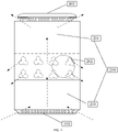
- Due to considerable heat generation, current network access equipment adopts fixed hole for heat dissipation, which has relatively concealed hole positions and limited heat dissipation. As shown in
FIG. 1 , small holes are opened at a bottom groove. Cold air is sucked from the bottom through the heat convection of air, passes through heat generation components on a mainboard and metal heat dissipation blocks, and is discharged from the top through convection to implement heat exchange. However, due to a long path of the entire heat exchange process, concealed hole positions, blockage of air by internal structures, and other reasons, heat generation cannot be effectively mitigated at an intermediate component position such as a circular position inFIG. 1 . - For the foregoing problems in some cases, there is currently no effective solution yet.
- Embodiments of the present disclosure provide a heat dissipation device, to solve at least to some extent one of the related technical problems including a problem that in some cases a heat dissipation manner in which small holes are opened at the bottom and the top of an apparatus to allow cold air to be sucked in from the bottom and discharged from the top through convection to implement heat exchange has low heat dissipation efficiency.
- According to an embodiment of the present disclosure, a heat dissipation device is provided. The heat dissipation device includes a housing. The housing includes a first sub-housing and a second sub-housing, the second sub-housing is adjacent to a bottom of the heat dissipation device, and the first sub-housing is adjacent to a top of the heat dissipation device. One or more holes are provided in a part of the second sub-housing that is overlapping the first sub-housing, the first sub-housing and the second sub-housing are capable of relative movement, and the relative movement is capable of exposing the one or more holes provided in the second sub-housing to form an air duct.
- The accompanying drawings described herein are intended to provide a further understanding of the present disclosure, and constitute a part of the present disclosure. The illustrative embodiments of the present disclosure and the description thereof are intended to describe the present disclosure, and do not constitute a limitation to the present disclosure. In the accompanying drawings:
-
FIG. 1 is a schematic structural diagram of a heat dissipation device in some cases; -
FIG. 2 is a schematic structural diagram of a heat dissipation device according to an embodiment of the present disclosure; -
FIG. 3 is a schematic structural diagram one of a heat dissipation device according to an embodiment of the present disclosure; -
FIG. 4 is a schematic structural diagram two of a heat dissipation device according to an embodiment of the present disclosure; -
FIG. 5 is a schematic structural diagram three of a heat dissipation device according to an embodiment of the present disclosure; -
FIG. 6 is a schematic structural diagram four of a heat dissipation device according to an embodiment of the present disclosure; and -
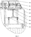
FIG. 7 is a schematic structural diagram five of a heat dissipation device according to an embodiment of the present disclosure. - The present disclosure is described below in detail with reference to the accompanying drawings and in combination with the embodiments. It is to be noted that the embodiments in the present disclosure and the features in the embodiments may be combined with each other if not conflicted.
- It is to be noted that the terms such as "first" and "second" in the description, claims and the foregoing accompanying drawings of the present disclosure are only intended to distinguish between similar objects, but are not necessarily intended to describe a specific sequence or a precedence order.
- 5G technology can bring users better user experience with transmission rates much higher than those of previous cellular networks, which may be up to 10 Gbit/s. Another advantage of 5G technology is low network latency and faster response speed. Due to outstanding advantages, 5G technology can meet application scenarios of large data transmission such as high-definition videos and virtual reality as well as low latency scenarios such as autonomous driving and telemedicine. However, the implementation of 5G places higher demands on hardware systems. High rates, low latency, multiple antennas, and other needs put more demanding requirements on heat generation scenarios of hardware. Current 4G terminals have relatively low power consumption because of low rates. In the 5G era, as the sizes of terminals remain unchanged, the power consumption of the terminals has increased significantly. Especially for network access equipment, innovative solutions are required for heat dissipation to meet normal operation conditions of various components of terminal products, so that the products can function normally and provide satisfying experience for users.
- The starting point of the embodiments of the present disclosure is based on the principle of heat dissipation through convection. An active convection air duct design is added without affecting the appearance, to allow a convection heat dissipation air duct of a product to make an adjustment according to a heat generation state of the product, and the air duct is designed to be as much as possible near components with high heat generation, thereby strengthening the air convection effect in key areas, shortening the length of the air duct to reduce the fan wind resistance, and optimizing the heat generation state of the product in different states, so as to maximize the hardware performance of the product and improve the performance of the product to meet user experience requirements of 5G products.
- It is be noted that the heat dissipation device in the embodiments of the present disclosure is applicable to, in addition to 5G products, products and equipment that require heat dissipation in other application scenarios, for example, 4G-related products and equipment, other communication equipment, and hardware equipment such as computer equipment.
- This embodiment provides a heat dissipation device.
FIG. 2 is a schematic structural diagram of a heat dissipation device according to an embodiment of the present disclosure. As shown inFIG. 2 , theheat dissipation device 11 includes ahousing 200. Thehousing 200 includes afirst sub-housing 201 and asecond sub-housing 203. Thesecond sub-housing 203 is adjacent to the bottom of theheat dissipation device 11, and thefirst sub-housing 201 is adjacent to the top of theheat dissipation device 11. - One or
more holes 202 are provided in a part of thesecond sub-housing 203 overlapping thefirst sub-housing 201, and thefirst sub-housing 201 and thesecond sub-housing 203 are capable of relative movement. The relative movement is capable of exposing the one ormore holes 202 provided in thesecond sub-housing 203 to form an air duct. - In some implementations of the present disclosure, the
housing 200 may be provided surrounding an apparatus to be subjected to heat dissipation. The apparatus to be subjected to heat dissipation includes abottom cover 103 at the bottom of the apparatus and atop cover 101 provided at the top of the apparatus. Air convection is formed between a hole provided in a groove at thebottom cover 103 and a hole provided in the top cover. - As can be seen, in the
heat dissipation device 11 in this embodiment of the present disclosure, because the one ormore holes 202 are provided in the part of thesecond sub-housing 203 overlapping thefirst sub-housing 201, in response to the relative movement between thefirst sub-housing 201 and thesecond sub-housing 203, the one ormore holes 202 provided in thesecond sub-housing 203 may be exposed to form the air duct, so that the heat dissipation efficiency for the apparatus is improved, thereby solving the problem that in some cases a heat dissipation manner in which small holes are opened at the bottom and the top of the apparatus to allow cold air to be sucked in from the bottom and discharged from the top through convection to implement heat exchange has low heat dissipation efficiency. - It is to be noted that although the
first sub-housing 201 and thesecond sub-housing 203 in thehousing 200 of theheat dissipation device 11 inFIG. 2 may be integrally provided, that is, the housing of the entireheat dissipation device 11 is formed by onefirst sub-housing 201 and onesecond sub-housing 203, certainly, sub-housings that are not integrally provided may be used. That is, a separatefirst sub-housing 201 and a separatesecond sub-housing 203 are provided on every side, or thefirst sub-housing 201 and thesecond sub-housing 203 are only provided on one or more sides instead of that thefirst sub-housings 201 and thesecond sub-housings 203 are provided on all sides. - In addition, no hole is provided in the
first sub-housings 201. Therefore, in a case that thefirst sub-housing 201 and thesecond sub-housing 203 overlap, the one ormore holes 202 in thesecond sub-housings 203 are blocked, that is, the air duct cannot be formed for cooling. In addition, the shape of the one ormore holes 202 inFIG. 2 is merely an example, and another shape may be used. For example, the one ormore holes 202 may be one or more circular holes or one or more rectangular holes. The shape of the one ormore holes 202 may be adjusted according to an actual requirement, and is not limited in the embodiments of the present disclosure. - In addition,
FIG. 2 only shows that there is only one row ofholes 202 in thesecond sub-housing 203. This is merely an example for description. The quantity of holes and the quantity of rows of holes may be set according to an actual requirement. As shown inFIG. 3 , two rows ofholes 202 are provided in thesecond sub-housing 203. - It is to be noted that the one or
more holes 202 in thesecond sub-housing 203 are provided in an area with relatively high heat generation of the apparatus, for example, a chip area. As shown inFIG. 2 , a dashed circle corresponds to an area with relatively high heat generation of the apparatus. In this way, in a case of relatively high workload, heat dissipation can be performed in the area in time, thereby improving the heat dissipation effect for this area. - As shown in
FIG. 4 , the heat dissipation device further includes amainboard support 405. - The
mainboard support 405 is assembled in the second sub-housing 203 from the bottom of the heat dissipation device. Thefirst sub-housing 201 is assembled in the second sub-housing 203 from the top of the heat dissipation device and is guided against an outer side wall of thesecond sub-housing 203. Themainboard support 405 is electrically connected to amainboard 406 of the apparatus to be subjected to heat dissipation by a lead. - In some implementations of the present disclosure, a
screw rod 404 is provided on themainboard support 405, and ascrew rod sleeve 502 is provided on thescrew rod 404. Thescrew rod 404 is fixedly connected to themainboard support 405. Thefirst sub-housing 201 is fixedly connected to thescrew rod sleeve 502 of thescrew rod 404. The manner of fixed connection may be a screw. - Rotation of the
screw rod 404 is capable of driving thescrew rod sleeve 502 to perform a reciprocating movement, and the reciprocating movement of thescrew rod sleeve 502 drives the relative movement between thefirst sub-housing 201 and thesecond sub-housing 203. - In some implementations of the present disclosure, the
heat dissipation device 11 further includes a drive motor. The drive motor is configured to receive a control instruction to drive thescrew rod 404 to perform the rotation. - It is to be noted that a first control instruction is sent to the drive motor in response to a temperature of the apparatus to be subjected to heat dissipation placed in the
housing 200 exceeding a first preset threshold. The first control instruction is configured to instruct the drive motor to drive thescrew rod 404 to perform the rotation to bring about the relative movement between thefirst sub-housing 201 and thesecond sub-housing 203, to expose the one or more holes provided in thesecond sub-housing 203 to form the air duct. A second control instruction is sent to the drive motor in response to the temperature of the apparatus to be subjected to heat dissipation placed in thehousing 200 being lower than a second preset threshold. The second control instruction is configured to instruct the drive motor to drive thescrew rod 404 to perform the rotation to bring about the relative movement between thefirst sub-housing 201 and thesecond sub-housing 203, to cause thefirst sub-housing 201 to cover the one ormore holes 202 in thesecond sub-housing 203. - Therefore, in an application scenario, after power up, the entire system operates. A temperature sensor inside a component detects an operating temperature at a critical position inside the component. When the temperature does not reach a preset start point, the system keeps a current state and continuously runs. Once it is detected that the temperature reaches a set high-temperature start point, the system drives the motor to bring about the relative movement between the
first sub-housing 201 and thesecond sub-housing 203 to expose the one ormore holes 202 provided in advance to form the air duct to accelerate heat dissipation, thereby ensuring reliable operation. Meanwhile, temperature detection is continuously performed. When it is detected that the temperature at the critical position drops and reaches a preset low-temperature start point, the system drives the motor to further drive thefirst sub-housing 201 to perform opposite movement relative to thesecond sub-housing 203, so that thefirst sub-housing 201 covers the one ormore holes 202 in thesecond sub-housing 203, thereby closing the air duct and keeping continuous operation of the system. During the operation of the entire machine, temperature detection remains in an operating state. When a user turns off the system, a motor mechanism detects the position of the air duct, and the system is turned off after the air duct is closed. - That is, in a common usage scenario, cold air enters from the bottom, is heated by the
mainboard 406, and is circulated to the top, to form convection cooling. In a long-time high-power consumption scenario, because the temperature in the chip area is excessively high, cold air cannot effectively reach the chip area. In this case, thefirst sub-housing 201 and thesecond sub-housing 203 are slid apart from each other by the motor under the control of a driver, to expose the one ormore holes 202 for heat dissipation of the chip area. Cold air can quickly reach a heat generation area of a chip of the mainboard under the action of a fan to form convection cooling. In response to the temperature dropping to a preset temperature or the power consumption in the usage scenario decreasing, the driver controls the motor to pull thefirst sub-housing 201 and thesecond sub-housing 203 to return to an original state to ensure the original appearance, to avoid the impact of dust or the like because heat dissipation holes are exposed for a long time, thereby meeting an active heat dissipation requirement of the apparatus. The apparatus may be a 5G apparatus or other hardware equipment, so that the heat dissipation performance of a component under a critical operation condition is greatly improved, thereby improving user experience. - As shown in
FIG. 5 , abuckle 503 is provided on the first sub-housing. Thebuckle 503 is connected to thefirst sub-housing 201 and thesecond sub-housing 203. - In an application scenario, in response to the
first sub-housing 201 moving under the drive of thescrew rod 404 and thesleeve 502, in one aspect, thefirst sub-housing 201 is limited by a stroke of thescrew rod 404, and in another aspect, abuckle 503 is used to ensure that during the movement of thefirst sub-housing 201 and thesecond sub-housing 203, thesecond sub-housing 203 and thefirst sub-housing 201 are prevented from being detached under an external force, thereby improving the assembly reliability of the entire machine. On an inner side of thebuckle 503, a hole is provided in thefirst sub-housing 201. When repair is required, a fixture is used to pry open the buckle through the position of the hole, thereby separating thesecond sub-housing 203 and thefirst sub-housing 201 to repair the entire machine. - In addition, as shown in
FIG. 5 , after assembly, thefirst sub-housing 201 and thescrew rod sleeve 502 are fixed by ascrew 501. Thescrew rod 404 and themainboard support 405 are fixed by ascrew 504. - As shown in
FIG. 6 , afan 601 is further provided on themainboard support 405. An air duct of thefan 601 is consistent with the air duct formed by exposing the one ormore holes 202 provided in thesecond sub-housing 203 through the relative movement. - That is, the
screw rod 404 drives thefirst sub-housing 201 to slide relative to thesecond sub-housing 203 to expose the one ormore holes 202 provided in advance. The exposed one ormore holes 202 form the air duct to allow cold air to be effectively provided, so that the cold air can quickly reach a heat dissipation fin area, the air duct of thefan 601 is shortened, and the air pressure is reduced, thereby improving the efficiency of thefan 601 and extending the service life of thefan 601. It is to be noted that the position of the fan in the embodiments of the present disclosure may be adjusted and set according to the solution design and thermal design of a product. - As shown in
FIG. 7 , asleeve guide rail 701 is provided on themainboard support 405. Afirst magnet 702 and asecond magnet 703 are provided inside thesleeve guide rail 701. Thefirst magnet 702 is provided at an end in the sleeve guide rail adjacent to themainboard support 405, and thesecond magnet 703 is provided at an end in the sleeve guide rail away from themainboard support 405. Themainboard support 405 is fixedly connected to thefirst sub-housing 201. - In an application scenario, the
first magnet 702 may be a permanent magnet, and thesecond magnet 703 may be an electromagnet. The electromagnet is energized to adjust the magnetic poles of the electromagnet to cause the electromagnet and the permanent magnet to attract each other or repel each other to cause themainboard support 405 to perform relative movement, so as to bring about the relative movement between thefirst sub-housing 201 and thesecond sub-housing 203. - Through the embodiments of the present disclosure, in the heat dissipation device in the embodiments of the present disclosure, because the one or more holes are provided in the part of the second sub-housing overlapping the first sub-housing, after the relative movement between the first sub-housing and the second sub-housing, the one or more holes provided in the second sub-housing may be exposed to form the air duct, so that the heat dissipation efficiency for the apparatus is improved, thereby solving the problem that in some cases a heat dissipation manner in which small holes are opened at the bottom and the top of the apparatus to allow cold air to be sucked in from the bottom and discharged from the top through convection to implement heat exchange has low heat dissipation efficiency.
- Described above are merely some embodiments of the present disclosure, and are not intended to limit the present disclosure. A person having ordinary skills in the art may make various changes and variations to the present disclosure. Within the principle of the present disclosure, any modifications, equivalent substitutions, improvements, and the like shall fall within the protection scope of the present disclosure.
Claims (8)
- A heat dissipation device, comprising a housing, wherein:the housing comprises a first sub-housing and a second sub-housing, the second sub-housing is configured to be adjacent to a bottom of the heat dissipation device, and the first sub-housing is configured to be adjacent to a top of the heat dissipation device; andone or more holes are provided in a part of the second sub-housing overlapping the first sub-housing, the first sub-housing and the second sub-housing are capable of relative movement, and the relative movement is capable of exposing the one or more holes provided in the second sub-housing to form an air duct.
- The heat dissipation device of claim 1, further comprising a mainboard support, wherein:
the mainboard support is assembled in the second sub-housing from the bottom of the heat dissipation device; the first sub-housing is assembled in the second sub-housing from the top of the heat dissipation device and is guided against an outer side wall of the second sub-housing; and the mainboard support is electrically connected by a lead to a mainboard of an apparatus to be subjected to heat dissipation. - The heat dissipation device of claim 2, wherein a screw rod is provided on the mainboard support, and a screw rod sleeve is provided on the screw rod; the screw rod is fixedly connected to the mainboard support; the first sub-housing is fixedly connected to the screw rod sleeve of the screw rod; and
rotation of the screw rod is capable of driving the screw rod sleeve to perform a reciprocating movement, and the reciprocating movement of the screw rod sleeve drives the relative movement between the first sub-housing and the second sub-housing. - The heat dissipation device of claim 3, further comprising a drive motor, wherein:
the drive motor is configured to receive a control instruction to drive the screw rod to perform the rotation. - The heat dissipation device of claim 4, wherein:a first control instruction is sent to the drive motor in response to a temperature of the apparatus to be subjected to heat dissipation placed in the housing exceeding a first preset threshold, wherein the first control instruction is configured to instruct the drive motor to drive the screw rod to perform the rotation to bring about the relative movement between the first sub-housing and the second sub-housing, to expose the one or more holes provided in the second sub-housing to form the air duct; anda second control instruction is sent to the drive motor in response to the temperature of the apparatus to be subjected to heat dissipation placed in the housing being lower than a second preset threshold, wherein the second control instruction is configured to instruct the drive motor to drive the screw rod to perform the rotation to bring about the relative movement between the first sub-housing and the second sub-housing, to cause the first sub-housing to cover the one or more holes in the second sub-housing.
- The heat dissipation device of claim 1, wherein a buckle is provided on the first sub-housing, and the buckle is connected to the first sub-housing and the second sub-housing.
- The heat dissipation device of claim 2, wherein a fan is further provided on the mainboard support, and an air duct of the fan is consistent with the air duct formed by exposing the one or more holes provided in the second sub-housing through the relative movement.
- The heat dissipation device of claim 2, wherein:a sleeve guide rail is provided on the mainboard support;a first magnet and a second magnet are provided inside the sleeve guide rail; the first magnet is provided at an end in the sleeve guide rail adjacent to the mainboard support, and the second magnet is provided at an end in the sleeve guide rail away from the mainboard support; the mainboard support is fixedly connected to the first sub-housing; andthe first magnet and the second magnet attract or repel each other to enable the mainboard support to perform relative movement, to bring about the relative movement between the first sub-housing and the second sub-housing.
Applications Claiming Priority (2)
| Application Number | Priority Date | Filing Date | Title |
|---|---|---|---|
| CN201911285515.XA CN112996342B (en) | 2019-12-13 | 2019-12-13 | Heat dissipation device |
| PCT/CN2020/118101 WO2021114823A1 (en) | 2019-12-13 | 2020-09-27 | Heat dissipation device |
Publications (3)
| Publication Number | Publication Date |
|---|---|
| EP4017232A1 true EP4017232A1 (en) | 2022-06-22 |
| EP4017232A4 EP4017232A4 (en) | 2022-10-12 |
| EP4017232B1 EP4017232B1 (en) | 2024-08-28 |
Family
ID=76329477
Family Applications (1)
| Application Number | Title | Priority Date | Filing Date |
|---|---|---|---|
| EP20899235.4A Active EP4017232B1 (en) | 2019-12-13 | 2020-09-27 | Heat dissipation device |
Country Status (4)
| Country | Link |
|---|---|
| EP (1) | EP4017232B1 (en) |
| JP (1) | JP7386975B2 (en) |
| CN (1) | CN112996342B (en) |
| WO (1) | WO2021114823A1 (en) |
Families Citing this family (4)
| Publication number | Priority date | Publication date | Assignee | Title |
|---|---|---|---|---|
| CN113840524B (en) * | 2021-10-14 | 2024-02-27 | 国网江苏省电力有限公司宿迁供电分公司 | Security operation and maintenance audit operation integrated terminal and protection method |
| CN114400883B (en) * | 2021-12-28 | 2023-04-21 | 江苏力普通瑞电力电子科技有限公司 | High-voltage inverter pre-charging system convenient to maintain |
| CN114857698B (en) * | 2022-05-31 | 2024-04-02 | Tcl空调器(中山)有限公司 | Humidification subassembly and clarifier |
| CN117929822B (en) * | 2024-01-30 | 2024-11-19 | 常州东晟合众节能科技有限公司 | Ammeter case with safety protection function |
Family Cites Families (17)
| Publication number | Priority date | Publication date | Assignee | Title |
|---|---|---|---|---|
| JPH1154975A (en) * | 1997-07-31 | 1999-02-26 | Ricoh Co Ltd | Exhaust device in housing |
| KR20030092261A (en) * | 2002-05-29 | 2003-12-06 | 발레오만도전장시스템스코리아 주식회사 | Assembling Structure for Alternator with Heat-sink Plate |
| JP2007234791A (en) * | 2006-02-28 | 2007-09-13 | Fuji Electric Retail Systems Co Ltd | Electronic apparatus cooling device |
| JP5835067B2 (en) * | 2011-07-04 | 2015-12-24 | 株式会社Jvcケンウッド | projector |
| KR101506907B1 (en) * | 2014-11-18 | 2015-03-30 | (주)위너스라이팅 | Phase change cooling unit |
| CN204231854U (en) * | 2014-12-02 | 2015-03-25 | 南京润杰电控设备有限公司 | A kind of control cubicle heat abstractor |
| CN105555082B (en) * | 2016-01-18 | 2018-07-06 | 杭州奕胜科技有限公司 | A kind of vehicle power amplifier shell |
| CN106982537B (en) * | 2016-01-19 | 2021-04-20 | 中兴通讯股份有限公司 | Infinitely adjustable method and device for air duct wind resistance |
| CN205725400U (en) * | 2016-04-27 | 2016-11-23 | 金仕泽 | Magnetomotive mechanism |
| US11364142B2 (en) * | 2016-05-11 | 2022-06-21 | Vivonics, Inc. | Cooling system and method for a prosthetic socket |
| CN106852046B (en) * | 2017-02-10 | 2023-04-07 | 浙江远望通信技术有限公司 | Novel outdoor electronic equipment box |
| CN107979950A (en) * | 2017-11-13 | 2018-05-01 | 中国航空工业集团公司西安航空计算技术研究所 | The automatic of ventilation integrated stand divides wind apparatus |
| CN209043090U (en) * | 2018-09-12 | 2019-06-28 | 天津市利鑫达夏星散热器股份有限公司 | A kind of portable aluminium alloy heat radiator |
| CN109585732A (en) * | 2018-11-21 | 2019-04-05 | 合肥泽尼特新能源有限公司 | A kind of new energy car battery radiating sleeve |
| CN109981867A (en) * | 2019-03-26 | 2019-07-05 | 努比亚技术有限公司 | Heat dissipating method, mobile terminal and computer readable storage medium |
| CN209675520U (en) * | 2019-04-10 | 2019-11-22 | 东莞市煜锦实业有限公司 | A kind of connector with radiator |
| CN110454423B (en) * | 2019-08-19 | 2025-01-24 | 珠海格力电器股份有限公司 | Cooling and heating fan |
-
2019
- 2019-12-13 CN CN201911285515.XA patent/CN112996342B/en active Active
-
2020
- 2020-09-27 EP EP20899235.4A patent/EP4017232B1/en active Active
- 2020-09-27 JP JP2022517259A patent/JP7386975B2/en active Active
- 2020-09-27 WO PCT/CN2020/118101 patent/WO2021114823A1/en not_active Ceased
Also Published As
| Publication number | Publication date |
|---|---|
| CN112996342B (en) | 2025-12-19 |
| JP2022548666A (en) | 2022-11-21 |
| EP4017232A4 (en) | 2022-10-12 |
| WO2021114823A1 (en) | 2021-06-17 |
| JP7386975B2 (en) | 2023-11-27 |
| CN112996342A (en) | 2021-06-18 |
| EP4017232B1 (en) | 2024-08-28 |
Similar Documents
| Publication | Publication Date | Title |
|---|---|---|
| EP4017232B1 (en) | Heat dissipation device | |
| US9907202B2 (en) | Electronic equipment | |
| US20180173284A1 (en) | Heat sink for use in storage and associated storage | |
| CN110678052B (en) | Mobile phone with heat radiation module | |
| CN105451503A (en) | Electronic equipment | |
| CN110650619B (en) | Mobile phone with heat radiation module | |
| CN210840499U (en) | Electronic equipment | |
| CN201149299Y (en) | Insect-proof electromagnetic oven | |
| CN111147901B (en) | Heat radiation structure of set top box | |
| CN108571125A (en) | A kind of new structure fire skylight | |
| CN114489287B (en) | Efficient dustproof rack-mounted server | |
| CN118054314A (en) | An outdoor cabinet | |
| CN204102217U (en) | A kind of entrance guard device | |
| CN108447742B (en) | Energy-saving electromagnetic switch | |
| CN220359494U (en) | Electric control box | |
| CN217656880U (en) | Internet of things gateway controller | |
| CN222621404U (en) | Electronic equipment | |
| CN207354477U (en) | Laser television host radiator window opening and closing structure | |
| CN215529736U (en) | Electronic power equipment customization intelligent radiator structure | |
| CN223294994U (en) | A water-cooled air-conditioning controller with overload protection | |
| CN216216961U (en) | Intelligent heat dissipation assembly of Ethernet switch host | |
| CN223950532U (en) | Elevator control cabinet | |
| CN213546235U (en) | Electromagnet mechanism for controlling and protecting switch electric appliance | |
| CN114446715B (en) | Electromagnetic-based overheat protection relay | |
| CN221380201U (en) | Low-voltage intelligent power distribution and utilization switch cabinet based on Internet of things |
Legal Events
| Date | Code | Title | Description |
|---|---|---|---|
| STAA | Information on the status of an ep patent application or granted ep patent |
Free format text: STATUS: THE INTERNATIONAL PUBLICATION HAS BEEN MADE |
|
| PUAI | Public reference made under article 153(3) epc to a published international application that has entered the european phase |
Free format text: ORIGINAL CODE: 0009012 |
|
| STAA | Information on the status of an ep patent application or granted ep patent |
Free format text: STATUS: REQUEST FOR EXAMINATION WAS MADE |
|
| 17P | Request for examination filed |
Effective date: 20220317 |
|
| AK | Designated contracting states |
Kind code of ref document: A1 Designated state(s): AL AT BE BG CH CY CZ DE DK EE ES FI FR GB GR HR HU IE IS IT LI LT LU LV MC MK MT NL NO PL PT RO RS SE SI SK SM TR |
|
| A4 | Supplementary search report drawn up and despatched |
Effective date: 20220913 |
|
| RIC1 | Information provided on ipc code assigned before grant |
Ipc: H05K 5/02 20060101ALI20220907BHEP Ipc: F21V 15/01 20060101ALI20220907BHEP Ipc: H05K 7/14 20060101ALI20220907BHEP Ipc: F21V 29/83 20150101ALI20220907BHEP Ipc: H05K 7/20 20060101AFI20220907BHEP |
|
| DAV | Request for validation of the european patent (deleted) | ||
| DAX | Request for extension of the european patent (deleted) | ||
| GRAP | Despatch of communication of intention to grant a patent |
Free format text: ORIGINAL CODE: EPIDOSNIGR1 |
|
| STAA | Information on the status of an ep patent application or granted ep patent |
Free format text: STATUS: GRANT OF PATENT IS INTENDED |
|
| INTG | Intention to grant announced |
Effective date: 20240531 |
|
| GRAS | Grant fee paid |
Free format text: ORIGINAL CODE: EPIDOSNIGR3 |
|
| GRAA | (expected) grant |
Free format text: ORIGINAL CODE: 0009210 |
|
| STAA | Information on the status of an ep patent application or granted ep patent |
Free format text: STATUS: THE PATENT HAS BEEN GRANTED |
|
| AK | Designated contracting states |
Kind code of ref document: B1 Designated state(s): AL AT BE BG CH CY CZ DE DK EE ES FI FR GB GR HR HU IE IS IT LI LT LU LV MC MK MT NL NO PL PT RO RS SE SI SK SM TR |
|
| REG | Reference to a national code |
Ref country code: CH Ref legal event code: EP |
|
| REG | Reference to a national code |
Ref country code: DE Ref legal event code: R096 Ref document number: 602020036870 Country of ref document: DE |
|
| REG | Reference to a national code |
Ref country code: IE Ref legal event code: FG4D |
|
| REG | Reference to a national code |
Ref country code: LT Ref legal event code: MG9D |
|
| PG25 | Lapsed in a contracting state [announced via postgrant information from national office to epo] |
Ref country code: NO Free format text: LAPSE BECAUSE OF FAILURE TO SUBMIT A TRANSLATION OF THE DESCRIPTION OR TO PAY THE FEE WITHIN THE PRESCRIBED TIME-LIMIT Effective date: 20241128 |
|
| REG | Reference to a national code |
Ref country code: AT Ref legal event code: MK05 Ref document number: 1719323 Country of ref document: AT Kind code of ref document: T Effective date: 20240828 |
|
| PG25 | Lapsed in a contracting state [announced via postgrant information from national office to epo] |
Ref country code: NL Free format text: LAPSE BECAUSE OF FAILURE TO SUBMIT A TRANSLATION OF THE DESCRIPTION OR TO PAY THE FEE WITHIN THE PRESCRIBED TIME-LIMIT Effective date: 20240828 Ref country code: PL Free format text: LAPSE BECAUSE OF FAILURE TO SUBMIT A TRANSLATION OF THE DESCRIPTION OR TO PAY THE FEE WITHIN THE PRESCRIBED TIME-LIMIT Effective date: 20240828 Ref country code: PT Free format text: LAPSE BECAUSE OF FAILURE TO SUBMIT A TRANSLATION OF THE DESCRIPTION OR TO PAY THE FEE WITHIN THE PRESCRIBED TIME-LIMIT Effective date: 20241230 Ref country code: GR Free format text: LAPSE BECAUSE OF FAILURE TO SUBMIT A TRANSLATION OF THE DESCRIPTION OR TO PAY THE FEE WITHIN THE PRESCRIBED TIME-LIMIT Effective date: 20241129 Ref country code: FI Free format text: LAPSE BECAUSE OF FAILURE TO SUBMIT A TRANSLATION OF THE DESCRIPTION OR TO PAY THE FEE WITHIN THE PRESCRIBED TIME-LIMIT Effective date: 20240828 |
|
| PG25 | Lapsed in a contracting state [announced via postgrant information from national office to epo] |
Ref country code: BG Free format text: LAPSE BECAUSE OF FAILURE TO SUBMIT A TRANSLATION OF THE DESCRIPTION OR TO PAY THE FEE WITHIN THE PRESCRIBED TIME-LIMIT Effective date: 20240828 |
|
| PG25 | Lapsed in a contracting state [announced via postgrant information from national office to epo] |
Ref country code: LV Free format text: LAPSE BECAUSE OF FAILURE TO SUBMIT A TRANSLATION OF THE DESCRIPTION OR TO PAY THE FEE WITHIN THE PRESCRIBED TIME-LIMIT Effective date: 20240828 |
|
| REG | Reference to a national code |
Ref country code: NL Ref legal event code: MP Effective date: 20240828 |
|
| PG25 | Lapsed in a contracting state [announced via postgrant information from national office to epo] |
Ref country code: AT Free format text: LAPSE BECAUSE OF FAILURE TO SUBMIT A TRANSLATION OF THE DESCRIPTION OR TO PAY THE FEE WITHIN THE PRESCRIBED TIME-LIMIT Effective date: 20240828 Ref country code: IS Free format text: LAPSE BECAUSE OF FAILURE TO SUBMIT A TRANSLATION OF THE DESCRIPTION OR TO PAY THE FEE WITHIN THE PRESCRIBED TIME-LIMIT Effective date: 20241228 |
|
| PG25 | Lapsed in a contracting state [announced via postgrant information from national office to epo] |
Ref country code: HR Free format text: LAPSE BECAUSE OF FAILURE TO SUBMIT A TRANSLATION OF THE DESCRIPTION OR TO PAY THE FEE WITHIN THE PRESCRIBED TIME-LIMIT Effective date: 20240828 |
|
| PG25 | Lapsed in a contracting state [announced via postgrant information from national office to epo] |
Ref country code: RS Free format text: LAPSE BECAUSE OF FAILURE TO SUBMIT A TRANSLATION OF THE DESCRIPTION OR TO PAY THE FEE WITHIN THE PRESCRIBED TIME-LIMIT Effective date: 20241128 Ref country code: ES Free format text: LAPSE BECAUSE OF FAILURE TO SUBMIT A TRANSLATION OF THE DESCRIPTION OR TO PAY THE FEE WITHIN THE PRESCRIBED TIME-LIMIT Effective date: 20240828 |
|
| PG25 | Lapsed in a contracting state [announced via postgrant information from national office to epo] |
Ref country code: RS Free format text: LAPSE BECAUSE OF FAILURE TO SUBMIT A TRANSLATION OF THE DESCRIPTION OR TO PAY THE FEE WITHIN THE PRESCRIBED TIME-LIMIT Effective date: 20241128 Ref country code: PT Free format text: LAPSE BECAUSE OF FAILURE TO SUBMIT A TRANSLATION OF THE DESCRIPTION OR TO PAY THE FEE WITHIN THE PRESCRIBED TIME-LIMIT Effective date: 20241230 Ref country code: PL Free format text: LAPSE BECAUSE OF FAILURE TO SUBMIT A TRANSLATION OF THE DESCRIPTION OR TO PAY THE FEE WITHIN THE PRESCRIBED TIME-LIMIT Effective date: 20240828 Ref country code: NO Free format text: LAPSE BECAUSE OF FAILURE TO SUBMIT A TRANSLATION OF THE DESCRIPTION OR TO PAY THE FEE WITHIN THE PRESCRIBED TIME-LIMIT Effective date: 20241128 Ref country code: NL Free format text: LAPSE BECAUSE OF FAILURE TO SUBMIT A TRANSLATION OF THE DESCRIPTION OR TO PAY THE FEE WITHIN THE PRESCRIBED TIME-LIMIT Effective date: 20240828 Ref country code: LV Free format text: LAPSE BECAUSE OF FAILURE TO SUBMIT A TRANSLATION OF THE DESCRIPTION OR TO PAY THE FEE WITHIN THE PRESCRIBED TIME-LIMIT Effective date: 20240828 Ref country code: IS Free format text: LAPSE BECAUSE OF FAILURE TO SUBMIT A TRANSLATION OF THE DESCRIPTION OR TO PAY THE FEE WITHIN THE PRESCRIBED TIME-LIMIT Effective date: 20241228 Ref country code: HR Free format text: LAPSE BECAUSE OF FAILURE TO SUBMIT A TRANSLATION OF THE DESCRIPTION OR TO PAY THE FEE WITHIN THE PRESCRIBED TIME-LIMIT Effective date: 20240828 Ref country code: GR Free format text: LAPSE BECAUSE OF FAILURE TO SUBMIT A TRANSLATION OF THE DESCRIPTION OR TO PAY THE FEE WITHIN THE PRESCRIBED TIME-LIMIT Effective date: 20241129 Ref country code: FI Free format text: LAPSE BECAUSE OF FAILURE TO SUBMIT A TRANSLATION OF THE DESCRIPTION OR TO PAY THE FEE WITHIN THE PRESCRIBED TIME-LIMIT Effective date: 20240828 Ref country code: ES Free format text: LAPSE BECAUSE OF FAILURE TO SUBMIT A TRANSLATION OF THE DESCRIPTION OR TO PAY THE FEE WITHIN THE PRESCRIBED TIME-LIMIT Effective date: 20240828 Ref country code: BG Free format text: LAPSE BECAUSE OF FAILURE TO SUBMIT A TRANSLATION OF THE DESCRIPTION OR TO PAY THE FEE WITHIN THE PRESCRIBED TIME-LIMIT Effective date: 20240828 Ref country code: AT Free format text: LAPSE BECAUSE OF FAILURE TO SUBMIT A TRANSLATION OF THE DESCRIPTION OR TO PAY THE FEE WITHIN THE PRESCRIBED TIME-LIMIT Effective date: 20240828 |
|
| PG25 | Lapsed in a contracting state [announced via postgrant information from national office to epo] |
Ref country code: RO Free format text: LAPSE BECAUSE OF FAILURE TO SUBMIT A TRANSLATION OF THE DESCRIPTION OR TO PAY THE FEE WITHIN THE PRESCRIBED TIME-LIMIT Effective date: 20240828 Ref country code: SM Free format text: LAPSE BECAUSE OF FAILURE TO SUBMIT A TRANSLATION OF THE DESCRIPTION OR TO PAY THE FEE WITHIN THE PRESCRIBED TIME-LIMIT Effective date: 20240828 Ref country code: DK Free format text: LAPSE BECAUSE OF FAILURE TO SUBMIT A TRANSLATION OF THE DESCRIPTION OR TO PAY THE FEE WITHIN THE PRESCRIBED TIME-LIMIT Effective date: 20240828 |
|
| PG25 | Lapsed in a contracting state [announced via postgrant information from national office to epo] |
Ref country code: EE Free format text: LAPSE BECAUSE OF FAILURE TO SUBMIT A TRANSLATION OF THE DESCRIPTION OR TO PAY THE FEE WITHIN THE PRESCRIBED TIME-LIMIT Effective date: 20240828 |
|
| PG25 | Lapsed in a contracting state [announced via postgrant information from national office to epo] |
Ref country code: CZ Free format text: LAPSE BECAUSE OF FAILURE TO SUBMIT A TRANSLATION OF THE DESCRIPTION OR TO PAY THE FEE WITHIN THE PRESCRIBED TIME-LIMIT Effective date: 20240828 |
|
| PG25 | Lapsed in a contracting state [announced via postgrant information from national office to epo] |
Ref country code: SK Free format text: LAPSE BECAUSE OF FAILURE TO SUBMIT A TRANSLATION OF THE DESCRIPTION OR TO PAY THE FEE WITHIN THE PRESCRIBED TIME-LIMIT Effective date: 20240828 |
|
| REG | Reference to a national code |
Ref country code: CH Ref legal event code: PL |
|
| PG25 | Lapsed in a contracting state [announced via postgrant information from national office to epo] |
Ref country code: LU Free format text: LAPSE BECAUSE OF NON-PAYMENT OF DUE FEES Effective date: 20240927 |
|
| REG | Reference to a national code |
Ref country code: DE Ref legal event code: R097 Ref document number: 602020036870 Country of ref document: DE |
|
| PLBE | No opposition filed within time limit |
Free format text: ORIGINAL CODE: 0009261 |
|
| STAA | Information on the status of an ep patent application or granted ep patent |
Free format text: STATUS: NO OPPOSITION FILED WITHIN TIME LIMIT |
|
| PG25 | Lapsed in a contracting state [announced via postgrant information from national office to epo] |
Ref country code: MC Free format text: LAPSE BECAUSE OF FAILURE TO SUBMIT A TRANSLATION OF THE DESCRIPTION OR TO PAY THE FEE WITHIN THE PRESCRIBED TIME-LIMIT Effective date: 20240828 |
|
| REG | Reference to a national code |
Ref country code: BE Ref legal event code: MM Effective date: 20240930 |
|
| PG25 | Lapsed in a contracting state [announced via postgrant information from national office to epo] |
Ref country code: BE Free format text: LAPSE BECAUSE OF NON-PAYMENT OF DUE FEES Effective date: 20240930 |
|
| PG25 | Lapsed in a contracting state [announced via postgrant information from national office to epo] |
Ref country code: FR Free format text: LAPSE BECAUSE OF NON-PAYMENT OF DUE FEES Effective date: 20241028 |
|
| GBPC | Gb: european patent ceased through non-payment of renewal fee |
Effective date: 20241128 |
|
| PG25 | Lapsed in a contracting state [announced via postgrant information from national office to epo] |
Ref country code: CH Free format text: LAPSE BECAUSE OF NON-PAYMENT OF DUE FEES Effective date: 20240930 |
|
| PG25 | Lapsed in a contracting state [announced via postgrant information from national office to epo] |
Ref country code: IE Free format text: LAPSE BECAUSE OF NON-PAYMENT OF DUE FEES Effective date: 20240927 |
|
| 26N | No opposition filed |
Effective date: 20250530 |
|
| PG25 | Lapsed in a contracting state [announced via postgrant information from national office to epo] |
Ref country code: SE Free format text: LAPSE BECAUSE OF FAILURE TO SUBMIT A TRANSLATION OF THE DESCRIPTION OR TO PAY THE FEE WITHIN THE PRESCRIBED TIME-LIMIT Effective date: 20240828 |
|
| PGFP | Annual fee paid to national office [announced via postgrant information from national office to epo] |
Ref country code: DE Payment date: 20250919 Year of fee payment: 6 |
|
| PGFP | Annual fee paid to national office [announced via postgrant information from national office to epo] |
Ref country code: IT Payment date: 20250923 Year of fee payment: 6 |
|
| PG25 | Lapsed in a contracting state [announced via postgrant information from national office to epo] |
Ref country code: GB Free format text: LAPSE BECAUSE OF NON-PAYMENT OF DUE FEES Effective date: 20241128 |
|
| PG25 | Lapsed in a contracting state [announced via postgrant information from national office to epo] |
Ref country code: CY Free format text: LAPSE BECAUSE OF FAILURE TO SUBMIT A TRANSLATION OF THE DESCRIPTION OR TO PAY THE FEE WITHIN THE PRESCRIBED TIME-LIMIT; INVALID AB INITIO Effective date: 20200927 |
|
| PG25 | Lapsed in a contracting state [announced via postgrant information from national office to epo] |
Ref country code: HU Free format text: LAPSE BECAUSE OF FAILURE TO SUBMIT A TRANSLATION OF THE DESCRIPTION OR TO PAY THE FEE WITHIN THE PRESCRIBED TIME-LIMIT; INVALID AB INITIO Effective date: 20200927 |