Technical Field
-
The present invention relates to lighting technology, and in particular to a sensor module for a lighting system, a corresponding lighting system, a method of operating the sensor module, and a processing means for the sensor module.
Background Art
-
In lighting systems, presence or motion sensors are used to sense a presence of persons within a sensing zone of the sensor, and to actuate a relay to turn on a load, such as a luminaire illuminating the sensing zone, or to send a command using a bus system.
-
Such an actuation may also be initiated by a remote controller of the lighting system, to which the sensor reports whenever it senses a presence of persons within its sensing zone. Typically, the communication with the remote controller may be realized via a Digital Addressable Lighting Interface (DALI) communication bus. Due to energy-saving measures such building automation busses typically have a limited traffic capacity.
-
Similar considerations apply for new technologies like Narrowband Internet of Things (NB-IoT) or other wireless mesh technologies. Typically, IoT applications collect sensor information for processing in the cloud.
-
Similarly, the presence of persons may be reported to the remote controller in order to provide several new digital service applications like Desk Management. For example, cleaning of office workspace may be guided based on information such as a daily occupancy time per desk. A plurality of sensors within the workspace may consistently report any presence of persons in their respective sensing zone to the remote controller upon sensing, so that the remote controller may then calculate the daily occupancy time per desk. This may result in heavy traffic on the communication bus when a plurality of sensors steadily reports movement data. In view of the limited traffic capacity of the communication bus, a proper operation of the lighting systems may be at risk.
Summary of the Invention
-
The object of the present invention is thus to reduce an amount of traffic provided by presence or motion sensors of a lighting system in support of new digital service applications.
-
The invention is defined by the appended independent claims. Preferred embodiments are set forth in the dependent claims and in the following description and drawings.
-
According to a first aspect, a sensor module for a lighting system is provided. The sensor module comprises sensing means and processing means. The sensing means are configured to sense a presence of a person within a sensing zone at a time instant, wherein the time instant falls within a corresponding unit time period of a time grid. The processing means is configured to aggregate those of the plurality of unit time periods in which the sensing means senses the presence of the person.
-
The sensing means may comprise a presence sensor or a motion sensor.
-
The processing means may comprise a counter configured for aggregating those of the plurality of unit time periods in which the sensing means senses the presence of the person.
-
The unit time period may relate to a second, a minute, and/or an hour.
-
The sensor module may further comprise communication means configured to communicate with a remote controller for the sensing means.
-
The communication means may be configured to report the aggregated unit time periods to the controller in accordance with a timing of a clock of the sensor module.
-
The timing of the clock of the sensor module may relate relating to an hourly, daily or weekly reporting period.
-
The communication means may be configured to report the aggregated unit time periods to the controller in accordance with a readout by the controller.
-
The communication means may comprise wireless communication.
-
The communication means may comprise wired communication, in particular a DALI interface connectable to a DALI bus or a KNX interface.
-
The processing means may further be configured to trigger, via the communication means, an activation of acoustic and/or lighting means for a time period, wherein the acoustic and/or lighting means may be arranged within the sensing zone of the sensor module.
-
The aggregated unit time periods may comprise an occupancy time of the sensing zone of the sensor module.
-
The activation of the lighting means may comprise activating a dimming level above a first dimming level if the occupancy time exceeds an occupancy time threshold.
-
The activation of the lighting means may comprise activating a dimming level below a second dimming level if the occupancy time fails to exceed the occupancy time threshold.
-
At least one of the levels and thresholds may be configurable via input means of the sensor module or, via the communication means, by the controller.
-
According to a second aspect, a lighting system is provided. The lighting system comprises a sensor module of the first aspect or any of its embodiments; and lighting means arranged in a sensing zone of the sensor module.
-
According to a third aspect, a method of operating a sensor module is provided. The method comprises: sensing a presence of a person within a sensing zone at a time instant, wherein the time instant falls within a corresponding unit time period of a time grid; and aggregating those of the plurality of unit time periods in which the presence of the person is sensed.
-
The method may be performed by a sensor module of the first aspect or any of its embodiments.
-
According to a fourth aspect, a processing means for a sensor module is provided. The processing means is designed for implementing the method of the third aspect or any of its embodiments.
Advantageous Effects of the Invention
-
The present disclosure foresees that information relevant for new digital service application is aggregated/calculated inside the sensor module, rather than reporting motion to the remote controller whenever it is detected. The aggregated information may then be submitted to or retrieved by the remote controller on a regular basis.
-
This may reduce an amount of traffic reported by presence or motion sensors of a lighting system in support of new digital service application, and may further allow for a deployment of a slow but cost-efficient and energy-saving bus system such as DALI or KNX
Brief Description of the Drawings
-
Further aspects, advantages and objects of the invention will become evident for the skilled reader by means of the following detailed description of the embodiments of the invention, when taking into conjunction with the figures of the enclosed drawings.
- Fig. 1 illustrates a sensor module in a lighting system according to an embodiment of the present disclosure; and
- Fig. 2 illustrates a method of operating a sensor module according to an embodiment of the present disclosure.
Detailed Descriptions of Embodiments
-
The invention will now be described with respect to various embodiments. The features of these embodiments may be combined with each other unless specified otherwise.
-
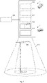
Fig. 1 illustrates a sensor module 1 in a lighting system 3 according to an embodiment of the present disclosure.
-
The lighting system 3 comprises the sensor module 1 and lighting means 108 arranged in a sensing zone 102 of the sensor module 1. In the example of Fig. 1, the lighting means 108 comprises a freestanding luminaire.
-
The sensor module 1 may be a separate component of the lighting system 3 or be integrated in the lighting means 108, such that the sensing zone 102 of the sensor module 1 comprises an illumination zone of the lighting means 108.
-
The sensor module 1 comprises sensing means 101 and processing means 103.
-
The sensing means 101 may comprise a presence sensor, a motion sensor or the like, irrespective of the underlying detection principle (such as pyroelectric effect, reflection of radar waves etc.).
-
The sensing means 101 is configured to sense a presence of a person within a sensing zone 102 at a time instant. This time instant falls within a corresponding unit time period of a time grid. The unit time period may relate to a second, a minute, and/or an hour. For example, whenever the presence of the person is sensed within the sensing zone 102, the corresponding second, minute, and/or hour of the time grid is identified accordingly.
-
Those skilled in the art will appreciate that depending on a motion within the sensing zone 102, the sensing means 101 may sense the presence of the person, or a non-presence of the person.
-
The processing means 103 may comprise a microcontroller, a microprocessor, a field-programmable gate array (FPGA), an application-specific integrated circuit (ASIC) or the like.
-
The processing means 103 may be designed for implementing the method 2 explained in more detail in connection with Fig. 2.
-
The processing means 103 is configured to aggregate those of the plurality of unit time periods in which the sensing means 101 senses the presence of the person. To this end, the processing means 103 may comprise a counter 104 configured for aggregating those of the plurality of unit time periods in which the sensing means 101 senses the presence of the person. In accordance with the previous example, those of the plurality of seconds in which the sensing means 101 senses the presence of the person may be aggregated by incrementing the counter 104 accordingly, so that the counter 104 has a value corresponding to the quantity of seconds in which the sensing means 101 sensed the presence of the person, since the counter 104 has been set to zero.
-
In particular, the aggregated unit time periods may comprise an occupancy time of the sensing zone 102 of the sensor module 1. In accordance with the previous example, if the sensing zone 102 of the sensor module 1 comprises a desk, the occupancy time of the desk amounts to the quantity of seconds in which the sensing means 101 sensed the presence of the person.
-
Based on presence information aggregated inside the sensor module 1, an amount of traffic reported by the sensor module 1 in support of new digital service applications may be reduced. In turn, this may further allow for a deployment of a slow but cost-efficient and energy-saving bus system such as DALI or KNX, as will be discussed next.
-
The sensor module 1 may further comprise communication means 105 configured to communicate with a remote controller 106 for the sensing means 101.
-
The communication means 105 may comprise wireless communication. Alternatively, the communication means 105 may comprise wired communication, in particular a DALI interface connectable to a DALI bus or a KNX interface.
-
The communication means 105 may be configured to report the aggregated unit time periods to the controller 106 in accordance with a timing of a clock 107 of the sensor module 1. Meanwhile, the timing of the clock 107 of the sensor module 1 may relate to an hourly, daily or weekly reporting period. In accordance with the previous example, the sensor module 1 may be configured to proactively report the aggregated plurality of seconds in which the sensing means 101 sensed the presence of the person to the controller 106.
-
Alternatively or additively, the communication means 105 may be configured to report the aggregated unit time periods to the controller 106 in accordance with a readout by the controller 106. In other words, the remote controller 106 may retrieve the aggregated plurality of seconds according to its own reporting schedule, so that the sensor module 1 in this case is configured to reactively report the aggregated plurality of seconds.
-
In other words, the aggregated information may be submitted to or retrieved by the remote controller 106 on a regular basis.
-
The processing means 103 may further configured to trigger, via the communication means 105, an activation of acoustic means and/or the lighting means 108 for a time period. The acoustic and/or lighting means 108 may be arranged within the sensing zone 102 of the sensor module 1.
-
The activation of the lighting means 108 may comprise activating a dimming level above a first dimming level if the occupancy time exceeds an occupancy time threshold. Alternatively or additionally, the activation of the lighting means 108 may comprise activating a dimming level below a second dimming level if the occupancy time fails to exceed the occupancy time threshold. In accordance with the previous example and given an occupancy time threshold of 5h per day, a dimming level of the corresponding lighting means 108 may be set to 100% if the occupancy time, i.e., the aggregated quantity of seconds in which the sensing means 101 sensed the presence of the person, amounts to more than these 5h, and otherwise to a dimming level of 10%, for example.
-
At least one of the levels and thresholds may be configurable via input means 109 of the sensor module 1, such as pushbuttons, or, via the communication means 105, by the controller 106 or a remote control for the sensor module 1.
-
Fig. 2 illustrates a method 2 of operating a sensor module 1 according to an embodiment of the present disclosure.
-
The method 2 comprises sensing 201 and aggregating 202 steps.
-
Step 201 involves sensing a presence of a person within a sensing zone at a time instant, wherein the time instant falls within a corresponding unit time period of a time grid.
-
Step 202 involves aggregating those of the plurality of unit time periods in which the presence of the person is sensed.
-
The method 2 may be performed by a sensor module 1 of the first aspect of the present disclosure or any of its embodiments.
-
Accordingly, the technical effects and advantages mentioned in connection with the sensor module 1 similarly apply for the method 2 of operating the same.