EP4017174A1 - Resource request method and apparatus, resource allocation method and apparatus, device, and medium - Google Patents
Resource request method and apparatus, resource allocation method and apparatus, device, and medium Download PDFInfo
- Publication number
- EP4017174A1 EP4017174A1 EP20853284.6A EP20853284A EP4017174A1 EP 4017174 A1 EP4017174 A1 EP 4017174A1 EP 20853284 A EP20853284 A EP 20853284A EP 4017174 A1 EP4017174 A1 EP 4017174A1
- Authority
- EP
- European Patent Office
- Prior art keywords
- resource
- bsr
- user equipment
- network device
- sending
- Prior art date
- Legal status (The legal status is an assumption and is not a legal conclusion. Google has not performed a legal analysis and makes no representation as to the accuracy of the status listed.)
- Granted
Links
Images


Classifications
-
- H—ELECTRICITY
- H04—ELECTRIC COMMUNICATION TECHNIQUE
- H04W—WIRELESS COMMUNICATION NETWORKS
- H04W28/00—Network traffic management; Network resource management
- H04W28/02—Traffic management, e.g. flow control or congestion control
- H04W28/0278—Traffic management, e.g. flow control or congestion control using buffer status reports
-
- H—ELECTRICITY
- H04—ELECTRIC COMMUNICATION TECHNIQUE
- H04W—WIRELESS COMMUNICATION NETWORKS
- H04W72/00—Local resource management
- H04W72/20—Control channels or signalling for resource management
- H04W72/21—Control channels or signalling for resource management in the uplink direction of a wireless link, i.e. towards the network
-
- H—ELECTRICITY
- H04—ELECTRIC COMMUNICATION TECHNIQUE
- H04W—WIRELESS COMMUNICATION NETWORKS
- H04W40/00—Communication routing or communication path finding
- H04W40/02—Communication route or path selection, e.g. power-based or shortest path routing
- H04W40/22—Communication route or path selection, e.g. power-based or shortest path routing using selective relaying for reaching a BTS [Base Transceiver Station] or an access point
-
- H—ELECTRICITY
- H04—ELECTRIC COMMUNICATION TECHNIQUE
- H04W—WIRELESS COMMUNICATION NETWORKS
- H04W72/00—Local resource management
- H04W72/20—Control channels or signalling for resource management
- H04W72/23—Control channels or signalling for resource management in the downlink direction of a wireless link, i.e. towards a terminal
-
- H—ELECTRICITY
- H04—ELECTRIC COMMUNICATION TECHNIQUE
- H04W—WIRELESS COMMUNICATION NETWORKS
- H04W72/00—Local resource management
- H04W72/20—Control channels or signalling for resource management
-
- H—ELECTRICITY
- H04—ELECTRIC COMMUNICATION TECHNIQUE
- H04W—WIRELESS COMMUNICATION NETWORKS
- H04W88/00—Devices specially adapted for wireless communication networks, e.g. terminals, base stations or access point devices
- H04W88/02—Terminal devices
- H04W88/04—Terminal devices adapted for relaying to or from another terminal or user
Definitions
- the present disclosure relates to the communications field, and in particular, to a resource request method and apparatus, a resource allocation method and apparatus, an equipment, and a medium.
- LTE Long term evolution
- UEs user equipments
- FIG. 1 is a schematic diagram of direct data transmission between UEs through a sidelink.
- the LTE supports sidelink relay, and "relay” means that a base station or a user does not send a signal to each other directly, but forwards the signal after signal amplification or regeneration processing through a relay node.
- a simple two-hop relay system for example, is to divide a "base station to mobile station” link into two links: “base station to relay node” and “relay node - mobile station", so that a poor-quality link can be replaced with two high-quality links, to achieve a higher link capacity and better coverage.
- remote UE and relay UE can perform direct data transmission.
- the remote UE and the relay UE need to acquire resources for the data transmission.
- Embodiments of the present disclosure provide a resource request method and apparatus, a resource allocation method and apparatus, an equipment, and a medium, to resolve the problem of inflexible resource acquisition.
- an embodiment of the present disclosure provides a resource request method, applied to a remote user equipment (UE), the method including:
- an embodiment of the present disclosure provides a resource request method, applied to a remote UE, the method including:
- an embodiment of the present disclosure provides a resource allocation method, applied to a network device, the method including:
- an embodiment of the present disclosure provides a resource allocation method, applied to a network device, the method including:
- an embodiment of the present disclosure provides a resource request apparatus, applied to a remote UE, the apparatus including:
- an embodiment of the present disclosure provides a resource request apparatus, applied to a remote UE, the apparatus including:
- an embodiment of the present disclosure provides a resource allocation apparatus, applied to a network device, the apparatus including:
- an embodiment of the present disclosure provides a resource allocation apparatus, applied to a network device, the apparatus including:
- an embodiment of the present disclosure provides a UE, including a processor, a memory, and a computer program stored in the memory and executable on the processor, where when the computer program is executed by the processor, steps of the foregoing resource request method are implemented.
- an embodiment of the present disclosure provides a network device, including a processor, a memory, and a computer program stored in the memory and executable on the processor, where when the computer program is executed by the processor, steps of the foregoing resource allocation method are implemented.
- an embodiment of the present disclosure provides a computer-readable storage medium, storing a computer program, where when the computer program is executed by a processor, steps of the foregoing resource request method, or the foregoing resource allocation method are implemented.
- a first SR is sent to request a resource used for sending the first BSR, so that the first BSR is sent by using the resource. Because the first BSR can be used for requesting a first resource for data transmission from the remote UE to a relay UE and a second resource for data transmission from the relay UE to a network device, that is, the remote UE can request the first resource and the second resource, so that the resource acquisition becomes more flexible and the resource acquisition efficiency is improved.
- FIG. 2 shows a time sequence diagram of a resource request method according to an embodiment of the present disclosure. As shown in FIG. 2 , the resource request method includes the following steps.
- a network device sends information about a scheduling request (SR) resource to a remote user equipment (UE), and the remote UE receives the information about the SR resource.
- the SR resource may be a dedicated SR resource, and the dedicated SR resource is a resource for the remote UE to transmit an SR.
- the remote UE sends a first SR on the SR resource in a case that an uplink resource of the remote UE is insufficient to send a first buffer status report (BSR), and the network device receives the first SR.
- the first SR is used for requesting the network device to allocate a resource used for sending the first BSR to the remote UE
- the first BSR is used for requesting the network device to allocate a first resource and a second resource
- the first resource is a resource used for data transmission from the remote UE to a relay UE
- the second resource is a resource used for data transmission from the relay UE to the network device.
- An example in which the uplink resource of the remote UE is insufficient to send the first BSR may include: the maximum number of transmittable bits of the uplink resource of the remote UE is less than the number of bits required to send the first BSR.
- the first BSR is an uplink BSR
- the uplink BSR is used for requesting a base station to allocate a sidelink resource (i.e., the first resource) used for transmitting pending uplink data from the remote UE to the relay UE and an uplink resource (i.e., the second resource) used for transmitting the pending uplink data from the relay UE to the base station.
- a sidelink resource i.e., the first resource
- an uplink resource i.e., the second resource
- the resource request method further includes the following steps.
- the network device allocates, according to the first SR, a resource used for sending the first BSR.
- the network device sends information about the resource used for sending the first BSR to the remote UE, and the remote UE receives the information about the resource used for sending the first BSR.
- a first SR is sent to request a resource used for sending the first BSR, so that the first BSR is sent by using the resource.
- the first BSR can be used for requesting a first resource for data transmission from the remote UE to a relay UE and a second resource for data transmission from the relay UE to a network device, that is, the remote UE can not only request the first resource required for data transmission thereof, but also request the second resource required for data transmission of the relay UE without requiring each of the remote UE and the relay UE to request a resource. Therefore, the resource acquisition becomes more flexible and the resource acquisition efficiency is improved.
- FIG. 3 shows a time sequence diagram of a resource request method according to another embodiment of the present disclosure.
- the resource request method includes the following steps.
- a network device sends information about an SR resource to a remote UE, and the remote UE receives the information about the SR resource.
- the SR resource may be a dedicated SR resource.
- S204 Send a second SR on the SR resource in a case that an uplink resource of the remote UE is insufficient to send a second BSR and/or a third BSR.
- the second SR is used for requesting the network device to allocate a resource used for sending the second BSR and the third BSR to the remote UE
- the second BSR is used for requesting the network device to allocate a first resource
- the third BSR is used for requesting the network device to allocate a second resource
- the first resource is a resource used for data transmission from the remote UE to a relay UE
- the second resource is a resource used for data transmission from the relay UE to the network device.
- An example in which the uplink resource of the remote UE is insufficient to send the second BSR may include: the maximum number of transmittable bits of the uplink resource of the remote UE is less than the number of bits required to send the second BSR.
- An example in which the uplink resource of the remote UE is insufficient to send the third BSR may include: the maximum number of transmittable bits of the uplink resource of the remote UE is less than the number of bits required to send the third BSR.
- An example in which the uplink resource of the remote UE is insufficient to send the second BSR and the third BSR may include: the maximum number of transmittable bits of the uplink resource of the remote UE is less than a threshold, and the threshold is a sum of the number of bits required to send the second BSR and the number of bits required to send the third BSR.
- the second BSR may be a sidelink BSR
- the third BSR may be an uplink BSR
- the first resource may be a sidelink resource
- the second resource may be an uplink resource.
- the resource request method further includes the following steps.
- S206 The network device allocates, according to the second SR, a resource used for sending the second BSR and the third BSR.
- the network device sends information about the resource used for sending the second BSR and the third BSR to the remote UE, and the remote UE receives the information about the resource used for sending the second BSR and the third BSR.
- a second SR is sent to request a resource used for sending the second BSR and the third BSR, so that the second BSR and the third BSR are sent by using the resource.
- the second BSR and the third BSR are respectively used for requesting a first resource for data transmission from the remote UE to a relay UE and a second resource for data transmission from the relay UE to a network device, that is, the remote UE can not only request the first resource required for data transmission thereof, but also request the second resource required for data transmission of the relay UE without requiring each of the remote UE and the relay UE to request a resource. Therefore, the resource acquisition becomes more flexible and the resource acquisition efficiency is improved.
- the resource request method may further include:
- the relay UE re-selection includes at least one of the following: relay UE re-selection due to a sidelink measurement result being lower than a threshold, relay UE re-selection caused by an upper layer reason, or relay UE re-selection due to the relay UE stopping providing a service for the remote UE.
- the relay stop operation includes: termination of communication with the network device, or direct communication with the network device without going through the relay UE.
- the all canceled pending SRs include the first SR in the embodiment of FIG. 2 .
- the all canceled pending SRs include the second SR in the embodiment of FIG. 2 .
- FIG. 4 shows a schematic diagram of a communication scenario according to an embodiment of the present disclosure, and the embodiment of FIG. 2 or FIG. 3 is applied to the communication scenario.
- a remote UE and a relay UE are within a signal coverage of a network device.
- the remote UE is connected to the relay UE through a PC5 radio interface (corresponding to a sidelink), and the relay UE is connected to the network device through a Uu radio interface (corresponding to an uplink plus a downlink).
- Both the remote UE and the relay UE are in a radio resource control (RRC) connection state.
- RRC radio resource control
- a lone term evolution (LTE) sidelink is designed for a specific public safety affair (e.g., emergency communication at a disaster site such as a fire or an earthquake), vehicle to everything (V2X) communication, or the like.
- the V2X communication includes various services, for example, basic security communication, advanced (autonomous) driving, formation, or sensor expansion. Because the LTE sidelink only supports broadcast communication, it is mainly used for basic security communication. Other advanced V2X services with a strict requirement for quality of service (QoS) in terms of delay, reliability, or the like are supported by a new radio (NR) sidelink.
- QoS quality of service
- FIG. 5 shows a schematic structural diagram of a resource request apparatus 500 according to an embodiment of the present disclosure.
- the resource request apparatus 500 includes:
- the resource request apparatus 500 may further include: a first cancellation module, configured to cancel sending of all pending SRs and/or stop an SR prohibit timer in a case that the remote UE meets a condition for canceling SRs, the condition for canceling SRs including at least one of the following conditions: reselecting a relay UE, stopping a relay operation, or switching from a relay communication mode to a non-relay communication mode.
- a first cancellation module configured to cancel sending of all pending SRs and/or stop an SR prohibit timer in a case that the remote UE meets a condition for canceling SRs, the condition for canceling SRs including at least one of the following conditions: reselecting a relay UE, stopping a relay operation, or switching from a relay communication mode to a non-relay communication mode.
- FIG. 6 shows a schematic structural diagram of a resource request apparatus 600 according to another embodiment of the present disclosure.
- the resource request apparatus 600 includes:
- the resource request apparatus 600 may further include: a second cancellation module, configured to cancel sending of all pending SRs and/or stop an SR prohibit timer in a case that the remote UE meets a condition for canceling SRs, the condition for canceling SRs including at least one of the following conditions: reselecting a relay UE, stopping a relay operation, or switching from a relay communication mode to a non-relay communication mode.
- a second cancellation module configured to cancel sending of all pending SRs and/or stop an SR prohibit timer in a case that the remote UE meets a condition for canceling SRs, the condition for canceling SRs including at least one of the following conditions: reselecting a relay UE, stopping a relay operation, or switching from a relay communication mode to a non-relay communication mode.
- FIG. 7 shows a schematic structural diagram of a resource allocation apparatus 700 according to an embodiment of the present disclosure, and the resource allocation apparatus is applied to a network device.
- the resource allocation apparatus 700 includes:
- FIG. 8 shows a schematic structural diagram of a resource allocation apparatus 800 according to another embodiment of the present disclosure, and the resource allocation apparatus is applied to a network device.
- the resource allocation apparatus 800 includes:
- An embodiment of the present disclosure further provides a UE, including a processor, a memory, and a computer program stored in the memory and executable on the processor, where when the computer program is executed by the processor, various processes of the embodiments of the foregoing resource request method are implemented, and can achieve the same technical effects. To avoid repetition, details are not described herein again.
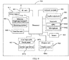
- FIG. 9 shows a schematic structural diagram of hardware of a UE 900 according to an embodiment of the present disclosure.
- the UE 900 includes, but is not limited to, components such as a radio frequency (RF) unit 901, a network module 902, an audio output unit 903, an input unit 904, a sensor 905, a display unit 906, a user input unit 907, an interface unit 908, a memory 109, a processor 910, and a power supply 911.
- RF radio frequency
- FIG. 9 does not constitute a limitation to the UE, and the UE may include more components or fewer components than those shown in the figure, or some components may be combined, or a different component deployment may be used.
- the UE includes, but is not limited to, a mobile phone, a tablet computer, a notebook computer, a palmtop computer, a vehicle-mounted terminal, a wearable device, a pedometer, and the like.
- the RF unit 901 is configured to receive information about an SR resource configured by a network device; send a first SR on the SR resource in a case that an uplink resource of a remote UE is insufficient to send a first BSR, the first SR being used for requesting the network device to allocate a resource used for sending the first BSR to the remote UE, the first BSR being used for requesting the network device to allocate a first resource and a second resource, the first resource being a resource used for data transmission from the remote UE to a relay UE, and the second resource being a resource used for data transmission from the relay UE to the network device; and receive information about the resource used for sending the first BSR sent by the network device.
- a first SR is sent to request a resource used for sending the first BSR, so that the first BSR is sent by using the resource. Because the first BSR can be used for requesting a first resource for data transmission from the remote UE to a relay UE and a second resource for data transmission from the relay UE to a network device, that is, the remote UE can request the first resource and the second resource at one time, the resource acquisition becomes more flexible and the resource acquisition efficiency is improved.
- the RF unit 901 is configured to receive and send a signal during an information receiving and sending process or a call process.
- the RF unit 501 is configured to receive downlink data from a base station, and then send the downlink data to the processor 910 for processing; and in addition, send uplink data to the base station.
- the RF unit 901 includes, but is not limited to, an antenna, at least one amplifier, a transceiver, a coupler, a low noise amplifier, a duplexer, and the like.
- the RF unit 901 may further communicate with a network device or another device through a wireless communications system.
- the UE provides wireless broadband Internet access for a user by using the network module 902. For example, the UE helps the user to receive and send an email, browse a webpage, and access stream media, and the like.
- the audio output unit 903 may convert audio data received by the RF unit 901 or the network module 902, or stored in the memory 109 into an audio signal and output the audio signal as a sound.
- the audio output unit 903 may further provide an audio output (for example, a call signal receiving sound or a message receiving sound) related to a specific function executed by the UE 900.
- the audio output unit 903 includes a loudspeaker, a buzzer, a receiver, and the like.
- the input unit 904 is configured to receive an audio signal or a video signal.
- the input unit 904 may include a graphics processing unit (GPU) 9041 and a microphone 9042.
- the GPU 9041 is configured to process image data of a static picture or a video obtained by an image capture apparatus (for example, a camera) in a video capture mode or an image capture mode.
- An image frame that has been processed may be displayed on the display unit 906.
- the image frame that has been processed by the GPU 9041 may be stored in the memory 109 (or another storage medium) or sent by using the RF unit 901 or the network module 902.
- the microphone 9042 may receive a sound, and can process the sound into audio data.
- the processed audio data may be converted, in a phone talk mode, into a format that may be sent to a mobile communication base station through the RF unit 901 for output.
- the UE 900 may further include at least one sensor 905, for example, an optical sensor, a motion sensor, and other sensors.
- the optical sensor includes an ambient light sensor and a proximity sensor.
- the ambient light sensor may adjust luminance of a display panel 9061 according to brightness of ambient light.
- the proximity sensor may switch off the display panel 9061 and/or backlight when the UE 900 is moved to the ear.
- an accelerometer sensor may detect a magnitude of acceleration in various directions (generally, three axes), and may detect a magnitude and a direction of gravity when static, which may be configured to recognize UE gestures (for example, horizontal and vertical screen switching, related games, and magnetometer posture calibration), vibration recognition related functions (for example, pedometer and tap), and the like.
- the sensor 905 may further include a fingerprint sensor, a pressure sensor, an iris sensor, a molecular sensor, a gyroscope, a barometer, a hygrometer, a thermometer, and an infrared sensor. Details are not described herein.
- the display unit 906 is configured to display information input by the user or information provided for the user.
- the display unit 906 may include a display panel 9061, which may be configured by using a liquid crystal display (LCD), an organic light-emitting diode (OLED), or the like.
- LCD liquid crystal display
- OLED organic light-emitting diode
- the user input unit 907 may be configured to receive inputted digital or character information, and generate a key signal input related to user settings and function control of the UE.
- the user input unit 907 includes a touch panel 9071 and another input device 9072.
- the touch panel 9071 also referred to as a touchscreen, may collect a touch operation of a user on or near the touch panel (for example, an operation of a user on the touch panel 9071 or near the touch panel 9071 by using any suitable object or accessory such as a finger or a stylus).
- the touch panel 9071 may include a touch detection apparatus and a touch controller. The touch detection apparatus detects a touch orientation of the user, detects a signal brought by the touch operation, and transmits the signal to the touch controller.
- the touch controller receives touch information from the touch detection apparatus, converts the touch information into a contact coordinate, then sends the contact coordinate to the processor 910, and receives and executes a command sent by the processor 910.
- the touch panel 9071 may be of a resistive type, a capacitive type, an infrared type, or a surface acoustic wave (SAW) type.
- the user input unit 907 may further include the another input device 9072.
- the another input device 9072 includes, but is not limited to, a physical keyboard, a functional key (for example, a volume control key or a switch key), a trackball, a mouse, and a joystick. Details are not described herein again.
- the touch panel 9071 may cover the display panel 9061. After detecting a touch operation on or near the touch panel 9071, the touch panel transfers the touch operation to the processor 910, so as to determine a type of the touch event. Then, the processor 910 provides corresponding visual output on the display panel 9061 according to the type of the touch event.
- the touch panel 9071 and the display panel 9061 are used as two separate parts to implement input and output functions of the UE, in some embodiments, the touch panel 9071 and the display panel 9061 may be integrated to implement the input and output functions of the UE, which is not specifically limited herein.
- the interface unit 908 is an interface used for connecting an external apparatus to the UE 900.
- the external apparatus may include a wired or wireless headset port, an external power supply (or a battery charger) port, a wired or wireless data port, a storage card port, a port used to for connecting an apparatus having an identification module, an audio input/output (I/O) port, a video I/O port, an earphone port, and the like.
- the interface unit 908 may be configured to receive an input (for example, data information or power) from the external apparatus, and transmit the received input to one or more elements in the UE 900, or may be configured to transmit data between the UE 900 and the external apparatus.
- the memory 109 may be configured to store a software program and various data.
- the memory 109 may mainly include a program storage area and a data storage area.
- the program storage area may store an operating system, an application program required by at least one function (for example, a sound playback function and an image playback function), or the like.
- the data storage area may store data (for example, audio data and a phone book) created according to use of the mobile phone.
- the memory 109 may include a high speed random access memory, and may further include a non-volatile memory, for example, at least one magnetic disk storage device, a flash memory device, or another non-volatile solid state storage device.
- the processor 910 is the control center of the UE, and is connected to various parts of the UE by using various interfaces and lines. By running or executing the software program and/or module stored in the memory 109, and invoking data stored in the memory 109, the processor performs various functions and data processing of the UE, thereby performing overall monitoring on the UE.
- the processor 910 may include one or more processing units.
- the processor 910 may integrate an application processor and a modem processor, where the application processor mainly processes an operating system, a user interface, an application program, and the like, and the modem processor mainly processes wireless communications. It may be understood that the foregoing modem may either not be integrated into the processor 910.
- the UE 900 may further include the power supply 911 (such as a battery) for supplying power to the components.
- the power supply 911 may be logically connected to the processor 910 by using a power management system, thereby implementing functions such as charging, discharging, and power consumption management by using the power management system.
- the UE 900 includes some functional modules that are not shown. Details are not described herein again.
- An embodiment of the present disclosure further provides a network device, including a processor, a memory, and a computer program stored in the memory and executable on the processor, where when the computer program is executed by the processor, various processes of the embodiments of the foregoing resource allocation method are implemented, and can achieve the same technical effects. To avoid repetition, details are not described herein again.
- An embodiment of the present disclosure further provides a computer-readable storage medium, storing a computer program, where when the computer program is executed by a processor, various processes of the foregoing resource request method or the foregoing resource allocation method are implemented, and can achieve the same technical effects. To avoid repetition, details are not described herein again.
- An example of the computer-readable storage medium includes a non-transitory computer-readable storage medium, for example, a read-only memory (ROM), a random access memory (RAM), a magnetic disk, or an optical disc.
- the terms “include”, “comprise”, and any variants thereof are intended to cover a non-exclusive inclusion. Therefore, in the context of a process, method, object, or apparatus that includes a series of elements, the process, method, object, or apparatus not only includes such elements, but also includes other elements not specified expressly, or may include inherent elements of the process, method, object, or apparatus. Without more limitations, elements defined by the sentence “including one” does not exclude that there are still other same elements in the processes, methods, objects, or apparatuses. In addition, the relational terms such as “first” and “second” are only used to differentiate an entity or operation from another, and do not necessarily require or imply any actual relationship or sequence between these entities or operations.
- a computer software product is stored in a storage medium (for example, a ROM/RAM, a magnetic disk, or an optical disc) and includes several instructions for instructing a terminal (a mobile phone, a computer, a server, an air conditioner, or a network device) to perform the methods described in the embodiments of the present disclosure.
- a storage medium for example, a ROM/RAM, a magnetic disk, or an optical disc
- a terminal a mobile phone, a computer, a server, an air conditioner, or a network device
Landscapes
- Engineering & Computer Science (AREA)
- Computer Networks & Wireless Communication (AREA)
- Signal Processing (AREA)
- Mobile Radio Communication Systems (AREA)
Abstract
Description
- The present disclosure claims priority to
Chinese Patent Application No. 201910755321.5, filed on August 15, 2019 - The present disclosure relates to the communications field, and in particular, to a resource request method and apparatus, a resource allocation method and apparatus, an equipment, and a medium.
- Long term evolution (LTE) systems support a sidelink from Release 12, and the sidelink is used for direct data transmission between user equipments (UEs) without going through a network device (e.g., a base station).
FIG. 1 is a schematic diagram of direct data transmission between UEs through a sidelink. - Currently, the LTE supports sidelink relay, and "relay" means that a base station or a user does not send a signal to each other directly, but forwards the signal after signal amplification or regeneration processing through a relay node. A simple two-hop relay system, for example, is to divide a "base station to mobile station" link into two links: "base station to relay node" and "relay node - mobile station", so that a poor-quality link can be replaced with two high-quality links, to achieve a higher link capacity and better coverage.
- In the related art, remote UE and relay UE can perform direct data transmission. However, before the remote UE and the relay UE perform direct data transmission, the remote UE and the relay UE need to acquire resources for the data transmission. However, in existing communication systems, it is inflexible for the remote UE and the relay UE to acquire resources for data transmission.
- Embodiments of the present disclosure provide a resource request method and apparatus, a resource allocation method and apparatus, an equipment, and a medium, to resolve the problem of inflexible resource acquisition.
- To resolve the foregoing technical problems, the present disclosure is implemented as follows.
- According to a first aspect, an embodiment of the present disclosure provides a resource request method, applied to a remote user equipment (UE), the method including:
- receiving information about a scheduling request (SR) resource configured by a network device;
- sending a first SR on the SR resource in a case that an uplink resource of the remote UE is insufficient to send a first buffer status report (BSR), the first SR being used for requesting the network device to allocate a resource used for sending the first BSR to the remote UE, the first BSR being used for requesting the network device to allocate a first resource and a second resource, the first resource being a resource used for data transmission from the remote UE to a relay UE, and the second resource being a resource used for data transmission from the relay UE to the network device; and
- receiving information about the resource used for sending the first BSR sent by the network device.
- According to a second aspect, an embodiment of the present disclosure provides a resource request method, applied to a remote UE, the method including:
- receiving information about an SR resource configured by a network device;
- sending a second SR on the SR resource in a case that an uplink resource of the remote UE is insufficient to send a second BSR and/or a third BSR, the second SR being used for requesting the network device to allocate a resource used for sending the second BSR and the third BSR to the remote UE, the second BSR being used for requesting the network device to allocate a first resource, the third BSR being used for requesting the network device to allocate a second resource, the first resource being a resource used for data transmission from the remote UE to a relay UE, and the second resource being a resource used for data transmission from the relay UE to the network device; and
- receiving information about the resource used for sending the second BSR and the third BSR sent by the network device.
- According to a third aspect, an embodiment of the present disclosure provides a resource allocation method, applied to a network device, the method including:
- sending information about an SR resource to a remote UE;
- receiving a first SR sent by the remote UE on the SR resource, the first SR being used for requesting the network device to allocate a resource used for sending a first BSR to the remote UE, the first BSR being used for requesting the network device to allocate a first resource and a second resource, the first resource being a resource used for data transmission from the remote UE to a relay UE, and the second resource being a resource used for data transmission from the relay UE to the network device;
- allocating, according to the first SR, the resource used for sending the first BSR; and
- sending information about the resource used for sending the first BSR to the remote UE.
- According to a fourth aspect, an embodiment of the present disclosure provides a resource allocation method, applied to a network device, the method including:
- sending information about an SR resource to a remote UE;
- receiving a second SR sent by the remote UE on the SR resource, the second SR being used for requesting the network device to allocate a resource used for sending a second BSR and a third BSR to the remote UE, the second BSR being used for requesting the network device to allocate a first resource, the third BSR being used for requesting the network device to allocate a second resource, the first resource being a resource used for data transmission from the remote UE to a relay UE, and the second resource being a resource used for data transmission from the relay UE to the network device;
- allocating, according to the second SR, the resource used for sending the second BSR and the third BSR; and
- sending information about the resource used for sending the second BSR and the third BSR to the remote UE.
- According to a fifth aspect, an embodiment of the present disclosure provides a resource request apparatus, applied to a remote UE, the apparatus including:
- a first resource receiving module, configured to receive information about an SR resource configured by a network device;
- a first SR sending module, configured to send a first SR on the SR resource in a case that an uplink resource of the remote UE is insufficient to send a first BSR, the first SR being used for requesting the network device to allocate a resource used for sending the first BSR to the remote UE, the first BSR being used for requesting the network device to allocate a first resource and a second resource, the first resource being a resource used for data transmission from the remote UE to a relay UE, and the second resource being a resource used for data transmission from the relay UE to the network device; and
- a second resource receiving module, configured to receive information about the resource used for sending the first BSR sent by the network device.
- According to a sixth aspect, an embodiment of the present disclosure provides a resource request apparatus, applied to a remote UE, the apparatus including:
- a third resource receiving module, configured to receive information about an SR resource configured by a network device;
- a second SR sending module, configured to send a second SR on the SR resource in a case that an uplink resource of the remote UE is insufficient to send a second BSR and/or a third BSR, the second SR being used for requesting the network device to allocate a resource used for sending the second BSR and the third BSR to the remote UE, the second BSR being used for requesting the network device to allocate a first resource, the third BSR being used for requesting the network device to allocate a second resource, the first resource being a resource used for data transmission from the remote UE to a relay UE, and the second resource being a resource used for data transmission from the relay UE to the network device; and
- a fourth resource receiving module, configured to receive information about the resource used for sending the second BSR and the third BSR sent by the network device.
- According to a seventh aspect, an embodiment of the present disclosure provides a resource allocation apparatus, applied to a network device, the apparatus including:
- a first resource sending module, configured to send information about an SR resource to a remote UE;
- a first SR receiving module, configured to receive a first SR sent by the remote UE on the SR resource, the first SR being used for requesting the network device to allocate a resource used for sending a first BSR to the remote UE, the first BSR being used for requesting the network device to allocate a first resource and a second resource, the first resource being a resource used for data transmission from the remote UE to a relay UE, and the second resource being a resource used for data transmission from the relay UE to the network device;
- a first resource allocation module, configured to allocate, according to the first SR, the resource used for sending the first BSR; and
- a second resource sending module, configured to send information about the resource used for sending the first BSR to the remote UE.
- According to an eighth aspect, an embodiment of the present disclosure provides a resource allocation apparatus, applied to a network device, the apparatus including:
- a third resource sending module, configured to send information about an SR resource to a remote UE;
- a second SR receiving module, configured to receive a second SR sent by the remote UE on the SR resource, the second SR being used for requesting the network device to allocate a resource used for sending a second BSR and a third BSR to the remote UE, the second BSR being used for requesting the network device to allocate a first resource, the third BSR being used for requesting the network device to allocate a second resource, the first resource being a resource used for data transmission from the remote UE to a relay UE, and the second resource being a resource used for data transmission from the relay UE to the network device;
- a second resource allocation module, configured to allocate, according to the second SR, the resource used for sending the second BSR and the third BSR; and
- a fourth resource sending module, configured to send information about the resource used for sending the second BSR and the third BSR to the remote UE.
- According to a ninth aspect, an embodiment of the present disclosure provides a UE, including a processor, a memory, and a computer program stored in the memory and executable on the processor, where when the computer program is executed by the processor, steps of the foregoing resource request method are implemented.
- According to a tenth aspect, an embodiment of the present disclosure provides a network device, including a processor, a memory, and a computer program stored in the memory and executable on the processor, where when the computer program is executed by the processor, steps of the foregoing resource allocation method are implemented.
- According to an eleventh aspect, an embodiment of the present disclosure provides a computer-readable storage medium, storing a computer program, where when the computer program is executed by a processor, steps of the foregoing resource request method, or the foregoing resource allocation method are implemented.
- In the embodiments of the present disclosure, in a case that an uplink resource of a remote UE is insufficient to send a first BSR, a first SR is sent to request a resource used for sending the first BSR, so that the first BSR is sent by using the resource. Because the first BSR can be used for requesting a first resource for data transmission from the remote UE to a relay UE and a second resource for data transmission from the relay UE to a network device, that is, the remote UE can request the first resource and the second resource, so that the resource acquisition becomes more flexible and the resource acquisition efficiency is improved.
- For better understanding of the present disclosure, specific implementations of the present disclosure are described below with reference to the accompanying drawings, and the same or similar reference numerals represent the same or similar features.
-
FIG. 1 shows a schematic diagram of direct data transmission between UEs through a sidelink. -
FIG. 2 shows a time sequence diagram of a resource request method according to an embodiment of the present disclosure. -
FIG. 3 shows a time sequence diagram of a resource request method according to another embodiment of the present disclosure. -
FIG. 4 shows a schematic diagram of a communication scenario according to an embodiment of the present disclosure. -
FIG. 5 shows a schematic structural diagram of a resource request apparatus according to an embodiment of the present disclosure. -
FIG. 6 shows a schematic structural diagram of a resource request apparatus according to another embodiment of the present disclosure. -
FIG. 7 shows a schematic structural diagram of a resource allocation apparatus according to an embodiment of the present disclosure. -
FIG. 8 shows a schematic structural diagram of a resource allocation apparatus according to another embodiment of the present disclosure. -
FIG. 9 shows a schematic structural diagram of hardware of a user equipment (UE) according to an embodiment of the present disclosure. - The following clearly and completely describes embodiments of the present disclosure with reference to the accompanying drawings in the embodiments of the present disclosure. Apparently, the described embodiments are some rather than all of the embodiments of the present disclosure. All other embodiments obtained by a person of ordinary skill in the art based on the embodiments of the present disclosure without creative efforts shall fall within the protection scope of the present disclosure.
-
FIG. 2 shows a time sequence diagram of a resource request method according to an embodiment of the present disclosure. As shown inFIG. 2 , the resource request method includes the following steps. - S102: A network device sends information about a scheduling request (SR) resource to a remote user equipment (UE), and the remote UE receives the information about the SR resource. The SR resource may be a dedicated SR resource, and the dedicated SR resource is a resource for the remote UE to transmit an SR.
- S104: The remote UE sends a first SR on the SR resource in a case that an uplink resource of the remote UE is insufficient to send a first buffer status report (BSR), and the network device receives the first SR. The first SR is used for requesting the network device to allocate a resource used for sending the first BSR to the remote UE, the first BSR is used for requesting the network device to allocate a first resource and a second resource, the first resource is a resource used for data transmission from the remote UE to a relay UE, and the second resource is a resource used for data transmission from the relay UE to the network device.
- An example in which the uplink resource of the remote UE is insufficient to send the first BSR may include: the maximum number of transmittable bits of the uplink resource of the remote UE is less than the number of bits required to send the first BSR.
- The first BSR is an uplink BSR, and the uplink BSR is used for requesting a base station to allocate a sidelink resource (i.e., the first resource) used for transmitting pending uplink data from the remote UE to the relay UE and an uplink resource (i.e., the second resource) used for transmitting the pending uplink data from the relay UE to the base station.
- The resource request method further includes the following steps.
- S106: The network device allocates, according to the first SR, a resource used for sending the first BSR.
- S108: The network device sends information about the resource used for sending the first BSR to the remote UE, and the remote UE receives the information about the resource used for sending the first BSR.
- In this embodiment of the present disclosure, in a case that an uplink resource of a remote UE is insufficient to send a first BSR, a first SR is sent to request a resource used for sending the first BSR, so that the first BSR is sent by using the resource. The first BSR can be used for requesting a first resource for data transmission from the remote UE to a relay UE and a second resource for data transmission from the relay UE to a network device, that is, the remote UE can not only request the first resource required for data transmission thereof, but also request the second resource required for data transmission of the relay UE without requiring each of the remote UE and the relay UE to request a resource. Therefore, the resource acquisition becomes more flexible and the resource acquisition efficiency is improved.
-
FIG. 3 shows a time sequence diagram of a resource request method according to another embodiment of the present disclosure. - As shown in
FIG. 3 , the resource request method includes the following steps. - S202: A network device sends information about an SR resource to a remote UE, and the remote UE receives the information about the SR resource. The SR resource may be a dedicated SR resource.
- S204: Send a second SR on the SR resource in a case that an uplink resource of the remote UE is insufficient to send a second BSR and/or a third BSR.
- The second SR is used for requesting the network device to allocate a resource used for sending the second BSR and the third BSR to the remote UE, the second BSR is used for requesting the network device to allocate a first resource, the third BSR is used for requesting the network device to allocate a second resource, the first resource is a resource used for data transmission from the remote UE to a relay UE, and the second resource is a resource used for data transmission from the relay UE to the network device.
- An example in which the uplink resource of the remote UE is insufficient to send the second BSR may include: the maximum number of transmittable bits of the uplink resource of the remote UE is less than the number of bits required to send the second BSR.
- An example in which the uplink resource of the remote UE is insufficient to send the third BSR may include: the maximum number of transmittable bits of the uplink resource of the remote UE is less than the number of bits required to send the third BSR.
- An example in which the uplink resource of the remote UE is insufficient to send the second BSR and the third BSR may include: the maximum number of transmittable bits of the uplink resource of the remote UE is less than a threshold, and the threshold is a sum of the number of bits required to send the second BSR and the number of bits required to send the third BSR.
- The second BSR may be a sidelink BSR, the third BSR may be an uplink BSR, the first resource may be a sidelink resource, and the second resource may be an uplink resource.
- The resource request method further includes the following steps.
- S206: The network device allocates, according to the second SR, a resource used for sending the second BSR and the third BSR.
- S208: The network device sends information about the resource used for sending the second BSR and the third BSR to the remote UE, and the remote UE receives the information about the resource used for sending the second BSR and the third BSR.
- In this embodiment of the present disclosure, in a case that an uplink resource of a remote UE is insufficient to send at least one BSR of a second BSR or a third BSR, a second SR is sent to request a resource used for sending the second BSR and the third BSR, so that the second BSR and the third BSR are sent by using the resource. The second BSR and the third BSR are respectively used for requesting a first resource for data transmission from the remote UE to a relay UE and a second resource for data transmission from the relay UE to a network device, that is, the remote UE can not only request the first resource required for data transmission thereof, but also request the second resource required for data transmission of the relay UE without requiring each of the remote UE and the relay UE to request a resource. Therefore, the resource acquisition becomes more flexible and the resource acquisition efficiency is improved.
- In the embodiment of
FIG. 2 or FIG. 3 , the resource request method may further include: - canceling sending of all pending SRs and/or stopping an SR prohibit timer in a case that the remote UE meets a condition for canceling SRs,
- the condition for canceling SRs including at least one of the following conditions: reselecting a relay UE, stopping a relay operation, or switching from a relay communication mode to a non-relay communication mode.
- The relay UE re-selection includes at least one of the following: relay UE re-selection due to a sidelink measurement result being lower than a threshold, relay UE re-selection caused by an upper layer reason, or relay UE re-selection due to the relay UE stopping providing a service for the remote UE.
- The relay stop operation includes: termination of communication with the network device, or direct communication with the network device without going through the relay UE.
- For the embodiment of
FIG. 2 , the all canceled pending SRs include the first SR in the embodiment ofFIG. 2 . For the embodiment ofFIG. 3 , the all canceled pending SRs include the second SR in the embodiment ofFIG. 2 . -
FIG. 4 shows a schematic diagram of a communication scenario according to an embodiment of the present disclosure, and the embodiment ofFIG. 2 or FIG. 3 is applied to the communication scenario. As shown inFIG. 4 , a remote UE and a relay UE are within a signal coverage of a network device. The remote UE is connected to the relay UE through a PC5 radio interface (corresponding to a sidelink), and the relay UE is connected to the network device through a Uu radio interface (corresponding to an uplink plus a downlink). 1) Both the remote UE and the relay UE are in a radio resource control (RRC) connection state. 2) Uplink data of the remote UE is forwarded to a base station through the relay UE. - A lone term evolution (LTE) sidelink is designed for a specific public safety affair (e.g., emergency communication at a disaster site such as a fire or an earthquake), vehicle to everything (V2X) communication, or the like. The V2X communication includes various services, for example, basic security communication, advanced (autonomous) driving, formation, or sensor expansion. Because the LTE sidelink only supports broadcast communication, it is mainly used for basic security communication. Other advanced V2X services with a strict requirement for quality of service (QoS) in terms of delay, reliability, or the like are supported by a new radio (NR) sidelink.
-
FIG. 5 shows a schematic structural diagram of a resource request apparatus 500 according to an embodiment of the present disclosure. - As shown in
FIG. 5 , the resource request apparatus 500 includes: - a first
resource receiving module 502, configured to receive information about an SR resource configured by a network device; - a first
SR sending module 504, configured to send a first SR on the SR resource in a case that an uplink resource of a remote UE is insufficient to send a first BSR, the first SR being used for requesting the network device to allocate a resource used for sending the first BSR to the remote UE, the first BSR being used for requesting the network device to allocate a first resource and a second resource, the first resource being a resource used for data transmission from the remote UE to a relay UE, and the second resource being a resource used for data transmission from the relay UE to the network device; and - a second
resource receiving module 506, configured to receive information about the resource used for sending the first BSR sent by the network device. - In an embodiment of the present disclosure, the resource request apparatus 500 may further include:
a first cancellation module, configured to cancel sending of all pending SRs and/or stop an SR prohibit timer in a case that the remote UE meets a condition for canceling SRs, the condition for canceling SRs including at least one of the following conditions: reselecting a relay UE, stopping a relay operation, or switching from a relay communication mode to a non-relay communication mode. -
FIG. 6 shows a schematic structural diagram of a resource request apparatus 600 according to another embodiment of the present disclosure. - As shown in
FIG. 6 , the resource request apparatus 600 includes: - a third
resource receiving module 602, configured to receive information about an SR resource configured by a network device; - a second
SR sending module 604, configured to send a second SR on the SR resource in a case that an uplink resource of a remote UE is insufficient to send a second BSR and/or a third BSR, the second SR being used for requesting the network device to allocate a resource used for sending the second BSR and the third BSR to the remote UE, the second BSR being used for requesting the network device to allocate a first resource, the third BSR being used for requesting the network device to allocate a second resource, the first resource being a resource used for data transmission from the remote UE to a relay UE, and the second resource being a resource used for data transmission from the relay UE to the network device; and - a fourth
resource receiving module 606, configured to receive information about the resource used for sending the second BSR and the third BSR sent by the network device. - In an embodiment of the present disclosure, the resource request apparatus 600 may further include:
a second cancellation module, configured to cancel sending of all pending SRs and/or stop an SR prohibit timer in a case that the remote UE meets a condition for canceling SRs, the condition for canceling SRs including at least one of the following conditions: reselecting a relay UE, stopping a relay operation, or switching from a relay communication mode to a non-relay communication mode. -
FIG. 7 shows a schematic structural diagram of a resource allocation apparatus 700 according to an embodiment of the present disclosure, and the resource allocation apparatus is applied to a network device. - As shown in
FIG. 7 , the resource allocation apparatus 700 includes: - a first
resource sending module 702, configured to send information about an SR resource to a remote UE; - a first
SR receiving module 704, configured to receive a first SR sent by the remote UE on the SR resource, the first SR being used for requesting the network device to allocate a resource used for sending a first BSR to the remote UE, the first BSR being used for requesting the network device to allocate a first resource and a second resource, the first resource being a resource used for data transmission from the remote UE to a relay UE, and the second resource being a resource used for data transmission from the relay UE to the network device; - a first
resource allocation module 706, configured to allocate, according to the first SR, the resource used for sending the first BSR; and - a second
resource sending module 708, configured to send information about the resource used for sending the first BSR to the remote UE. -
FIG. 8 shows a schematic structural diagram of a resource allocation apparatus 800 according to another embodiment of the present disclosure, and the resource allocation apparatus is applied to a network device. - As shown in
FIG. 8 , the resource allocation apparatus 800 includes: - a third
resource sending module 802, configured to send information about an SR resource to a remote UE; - a second
SR receiving module 804, configured to receive a second SR sent by the remote UE on the SR resource, the second SR being used for requesting the network device to allocate a resource used for sending a second BSR and a third BSR to the remote UE, the second BSR being used for requesting the network device to allocate a first resource, the third BSR being used for requesting the network device to allocate a second resource, the first resource being a resource used for data transmission from the remote UE to a relay UE, and the second resource being a resource used for data transmission from the relay UE to the network device; - a second
resource allocation module 806, configured to allocate, according to the second SR, the resource used for sending the second BSR and the third BSR; and - a fourth
resource sending module 808, configured to send information about the resource used for sending the second BSR and the third BSR to the remote UE. - An embodiment of the present disclosure further provides a UE, including a processor, a memory, and a computer program stored in the memory and executable on the processor, where when the computer program is executed by the processor, various processes of the embodiments of the foregoing resource request method are implemented, and can achieve the same technical effects. To avoid repetition, details are not described herein again.
- An example is used below for description of the UE provided by this embodiment of the present disclosure.
-
FIG. 9 shows a schematic structural diagram of hardware of aUE 900 according to an embodiment of the present disclosure. TheUE 900 includes, but is not limited to, components such as a radio frequency (RF)unit 901, anetwork module 902, anaudio output unit 903, aninput unit 904, asensor 905, adisplay unit 906, auser input unit 907, aninterface unit 908, a memory 109, aprocessor 910, and apower supply 911. A person skilled in the art may understand that the structure of the UE shown inFIG. 9 does not constitute a limitation to the UE, and the UE may include more components or fewer components than those shown in the figure, or some components may be combined, or a different component deployment may be used. In this embodiment of the present disclosure, the UE includes, but is not limited to, a mobile phone, a tablet computer, a notebook computer, a palmtop computer, a vehicle-mounted terminal, a wearable device, a pedometer, and the like. - The
RF unit 901 is configured to receive information about an SR resource configured by a network device; send a first SR on the SR resource in a case that an uplink resource of a remote UE is insufficient to send a first BSR, the first SR being used for requesting the network device to allocate a resource used for sending the first BSR to the remote UE, the first BSR being used for requesting the network device to allocate a first resource and a second resource, the first resource being a resource used for data transmission from the remote UE to a relay UE, and the second resource being a resource used for data transmission from the relay UE to the network device; and receive information about the resource used for sending the first BSR sent by the network device. - In this embodiment of the present disclosure, in a case that an uplink resource of a remote UE is insufficient to send a first BSR, a first SR is sent to request a resource used for sending the first BSR, so that the first BSR is sent by using the resource. Because the first BSR can be used for requesting a first resource for data transmission from the remote UE to a relay UE and a second resource for data transmission from the relay UE to a network device, that is, the remote UE can request the first resource and the second resource at one time, the resource acquisition becomes more flexible and the resource acquisition efficiency is improved.
- It should be understood that, in this embodiment of the present disclosure, the
RF unit 901 is configured to receive and send a signal during an information receiving and sending process or a call process. Specifically, the RF unit 501 is configured to receive downlink data from a base station, and then send the downlink data to theprocessor 910 for processing; and in addition, send uplink data to the base station. Generally, theRF unit 901 includes, but is not limited to, an antenna, at least one amplifier, a transceiver, a coupler, a low noise amplifier, a duplexer, and the like. In addition, theRF unit 901 may further communicate with a network device or another device through a wireless communications system. - The UE provides wireless broadband Internet access for a user by using the
network module 902. For example, the UE helps the user to receive and send an email, browse a webpage, and access stream media, and the like. - The
audio output unit 903 may convert audio data received by theRF unit 901 or thenetwork module 902, or stored in the memory 109 into an audio signal and output the audio signal as a sound. In addition, theaudio output unit 903 may further provide an audio output (for example, a call signal receiving sound or a message receiving sound) related to a specific function executed by theUE 900. Theaudio output unit 903 includes a loudspeaker, a buzzer, a receiver, and the like. - The
input unit 904 is configured to receive an audio signal or a video signal. Theinput unit 904 may include a graphics processing unit (GPU) 9041 and amicrophone 9042. TheGPU 9041 is configured to process image data of a static picture or a video obtained by an image capture apparatus (for example, a camera) in a video capture mode or an image capture mode. An image frame that has been processed may be displayed on thedisplay unit 906. The image frame that has been processed by theGPU 9041 may be stored in the memory 109 (or another storage medium) or sent by using theRF unit 901 or thenetwork module 902. Themicrophone 9042 may receive a sound, and can process the sound into audio data. The processed audio data may be converted, in a phone talk mode, into a format that may be sent to a mobile communication base station through theRF unit 901 for output. - The
UE 900 may further include at least onesensor 905, for example, an optical sensor, a motion sensor, and other sensors. Specifically, the optical sensor includes an ambient light sensor and a proximity sensor. The ambient light sensor may adjust luminance of adisplay panel 9061 according to brightness of ambient light. The proximity sensor may switch off thedisplay panel 9061 and/or backlight when theUE 900 is moved to the ear. As one type of motion sensor, an accelerometer sensor may detect a magnitude of acceleration in various directions (generally, three axes), and may detect a magnitude and a direction of gravity when static, which may be configured to recognize UE gestures (for example, horizontal and vertical screen switching, related games, and magnetometer posture calibration), vibration recognition related functions (for example, pedometer and tap), and the like. Thesensor 905 may further include a fingerprint sensor, a pressure sensor, an iris sensor, a molecular sensor, a gyroscope, a barometer, a hygrometer, a thermometer, and an infrared sensor. Details are not described herein. - The
display unit 906 is configured to display information input by the user or information provided for the user. Thedisplay unit 906 may include adisplay panel 9061, which may be configured by using a liquid crystal display (LCD), an organic light-emitting diode (OLED), or the like. - The
user input unit 907 may be configured to receive inputted digital or character information, and generate a key signal input related to user settings and function control of the UE. Specifically, theuser input unit 907 includes atouch panel 9071 and anotherinput device 9072. Thetouch panel 9071, also referred to as a touchscreen, may collect a touch operation of a user on or near the touch panel (for example, an operation of a user on thetouch panel 9071 or near thetouch panel 9071 by using any suitable object or accessory such as a finger or a stylus). Thetouch panel 9071 may include a touch detection apparatus and a touch controller. The touch detection apparatus detects a touch orientation of the user, detects a signal brought by the touch operation, and transmits the signal to the touch controller. The touch controller receives touch information from the touch detection apparatus, converts the touch information into a contact coordinate, then sends the contact coordinate to theprocessor 910, and receives and executes a command sent by theprocessor 910. In addition, thetouch panel 9071 may be of a resistive type, a capacitive type, an infrared type, or a surface acoustic wave (SAW) type. In addition to thetouch panel 9071, theuser input unit 907 may further include the anotherinput device 9072. Specifically, the anotherinput device 9072 includes, but is not limited to, a physical keyboard, a functional key (for example, a volume control key or a switch key), a trackball, a mouse, and a joystick. Details are not described herein again. - Further, the
touch panel 9071 may cover thedisplay panel 9061. After detecting a touch operation on or near thetouch panel 9071, the touch panel transfers the touch operation to theprocessor 910, so as to determine a type of the touch event. Then, theprocessor 910 provides corresponding visual output on thedisplay panel 9061 according to the type of the touch event. Although, inFIG. 9 , thetouch panel 9071 and thedisplay panel 9061 are used as two separate parts to implement input and output functions of the UE, in some embodiments, thetouch panel 9071 and thedisplay panel 9061 may be integrated to implement the input and output functions of the UE, which is not specifically limited herein. - The
interface unit 908 is an interface used for connecting an external apparatus to theUE 900. For example, the external apparatus may include a wired or wireless headset port, an external power supply (or a battery charger) port, a wired or wireless data port, a storage card port, a port used to for connecting an apparatus having an identification module, an audio input/output (I/O) port, a video I/O port, an earphone port, and the like. Theinterface unit 908 may be configured to receive an input (for example, data information or power) from the external apparatus, and transmit the received input to one or more elements in theUE 900, or may be configured to transmit data between theUE 900 and the external apparatus. - The memory 109 may be configured to store a software program and various data. The memory 109 may mainly include a program storage area and a data storage area. The program storage area may store an operating system, an application program required by at least one function (for example, a sound playback function and an image playback function), or the like. The data storage area may store data (for example, audio data and a phone book) created according to use of the mobile phone. In addition, the memory 109 may include a high speed random access memory, and may further include a non-volatile memory, for example, at least one magnetic disk storage device, a flash memory device, or another non-volatile solid state storage device.
- The
processor 910 is the control center of the UE, and is connected to various parts of the UE by using various interfaces and lines. By running or executing the software program and/or module stored in the memory 109, and invoking data stored in the memory 109, the processor performs various functions and data processing of the UE, thereby performing overall monitoring on the UE. Theprocessor 910 may include one or more processing units. Optionally, theprocessor 910 may integrate an application processor and a modem processor, where the application processor mainly processes an operating system, a user interface, an application program, and the like, and the modem processor mainly processes wireless communications. It may be understood that the foregoing modem may either not be integrated into theprocessor 910. - The
UE 900 may further include the power supply 911 (such as a battery) for supplying power to the components. Optionally, thepower supply 911 may be logically connected to theprocessor 910 by using a power management system, thereby implementing functions such as charging, discharging, and power consumption management by using the power management system. - In addition, the
UE 900 includes some functional modules that are not shown. Details are not described herein again. - An embodiment of the present disclosure further provides a network device, including a processor, a memory, and a computer program stored in the memory and executable on the processor, where when the computer program is executed by the processor, various processes of the embodiments of the foregoing resource allocation method are implemented, and can achieve the same technical effects. To avoid repetition, details are not described herein again.
- An embodiment of the present disclosure further provides a computer-readable storage medium, storing a computer program, where when the computer program is executed by a processor, various processes of the foregoing resource request method or the foregoing resource allocation method are implemented, and can achieve the same technical effects. To avoid repetition, details are not described herein again. An example of the computer-readable storage medium includes a non-transitory computer-readable storage medium, for example, a read-only memory (ROM), a random access memory (RAM), a magnetic disk, or an optical disc.
- It should be noted that, the terms "include", "comprise", and any variants thereof are intended to cover a non-exclusive inclusion. Therefore, in the context of a process, method, object, or apparatus that includes a series of elements, the process, method, object, or apparatus not only includes such elements, but also includes other elements not specified expressly, or may include inherent elements of the process, method, object, or apparatus. Without more limitations, elements defined by the sentence "including one" does not exclude that there are still other same elements in the processes, methods, objects, or apparatuses. In addition, the relational terms such as "first" and "second" are only used to differentiate an entity or operation from another, and do not necessarily require or imply any actual relationship or sequence between these entities or operations.
- According to the descriptions in the foregoing implementations, a person skilled in the art can clearly learn that the foregoing embodiment methods may be implemented by using software in combination with a necessary universal hardware platform. Certainly, the embodiment methods may also be implemented by using hardware, software, or a combination of the two, but the former is a preferred implementation in many cases. Based on such an understanding, the technical solutions of the present disclosure essentially or the part contributing to the existing technology may be implemented in a form of a software product. A computer software product is stored in a storage medium (for example, a ROM/RAM, a magnetic disk, or an optical disc) and includes several instructions for instructing a terminal (a mobile phone, a computer, a server, an air conditioner, or a network device) to perform the methods described in the embodiments of the present disclosure.
- The embodiments of the present disclosure have been described above with reference to the accompanying drawings. The present disclosure is not limited to the specific embodiments described above, and the specific embodiments described above are merely exemplary and not limitative. A person of ordinary skill in the art may make various variations under the teaching of the present disclosure without departing from the spirit of the present disclosure and the protection scope of the claims, and such variations shall all fall within the protection scope of the present disclosure.
Claims (19)
- A resource request method, applied to a remote user equipment, the method comprising:receiving information about a scheduling request (SR) resource configured by a network device;sending a first SR on the SR resource in a case that an uplink resource of the remote user equipment is insufficient to send a first buffer status report (BSR), the first SR being used for requesting the network device to allocate a resource used for sending the first BSR to the remote user equipment, the first BSR being used for requesting the network device to allocate a first resource and a second resource, the first resource being a resource used for data transmission from the remote user equipment to a relay user equipment, and the second resource being a resource used for data transmission from the relay user equipment to the network device; andreceiving information about the resource used for sending the first BSR sent by the network device.
- The method according to claim 1, further comprising:canceling sending of all pending SRs and/or stopping an SR prohibit timer in a case that the remote user equipment meets a condition for canceling SRs; whereinthe condition for canceling SRs comprises at least one of following conditions:
reselecting a relay user equipment, stopping a relay operation, or switching from a relay communication mode to a non-relay communication mode. - The method according to claim 2, wherein the all pending SRs comprise the first SR.
- A resource request method, applied to a remote user equipment, the method comprising:receiving information about a scheduling request (SR) resource configured by a network device;sending a second SR on the SR resource in a case that an uplink resource of the remote user equipment is insufficient to send a second buffer status report (BSR) and/or a third BSR, the second SR being used for requesting the network device to allocate a resource used for sending the second BSR and the third BSR to the remote user equipment, the second BSR being used for requesting the network device to allocate a first resource, the third BSR being used for requesting the network device to allocate a second resource, the first resource being a resource used for data transmission from the remote user equipment to a relay user equipment, and the second resource being a resource used for data transmission from the relay user equipment to the network device; andreceiving information about the resource used for sending the second BSR and the third BSR sent by the network device.
- The method according to claim 4, further comprising:canceling sending of all pending SRs and/or stopping an SR prohibit timer in a case that the remote user equipment meets a condition for canceling SRs; whereinthe condition for canceling SRs comprises at least one of following conditions:
reselecting a relay user equipment, stopping a relay operation, or switching from a relay communication mode to a non-relay communication mode. - The method according to claim 5, wherein the all pending SRs comprise the second SR.
- A resource allocation method, applied to a network device, the method comprising:sending information about a scheduling request (SR) resource to a remote user equipment;receiving a first SR sent by the remote user equipment on the SR resource, the first SR being used for requesting the network device to allocate a resource used for sending a first buffer status report (BSR) to the remote user equipment, the first BSR being used for requesting the network device to allocate a first resource and a second resource, the first resource being a resource used for data transmission from the remote user equipment to a relay user equipment, and the second resource being a resource used for data transmission from the relay user equipment to the network device;allocating, according to the first SR, the resource used for sending the first BSR; andsending information about the resource used for sending the first BSR to the remote user equipment.
- A resource allocation method, applied to a network device, the method comprising:sending information about a scheduling request (SR) resource to a remote user equipment;receiving a second SR sent by the remote user equipment on the SR resource, the second SR being used for requesting the network device to allocate a resource used for sending a second buffer status report (BSR) and a third BSR to the remote user equipment, the second BSR being used for requesting the network device to allocate a first resource, the third BSR being used for requesting the network device to allocate a second resource, the first resource being a resource used for data transmission from the remote user equipment to a relay user equipment, and the second resource being a resource used for data transmission from the relay user equipment to the network device;allocating, according to the second SR, the resource used for sending the second BSR and the third BSR; andsending information about the resource used for sending the second BSR and the third BSR to the remote user equipment.
- A resource request apparatus, applied to a remote user equipment, the apparatus comprising:a first resource receiving module, configured to receive information about a scheduling request (SR) resource configured by a network device;a first SR sending module, configured to send a first SR on the SR resource in a case that an uplink resource of the remote user equipment is insufficient to send a first buffer status report (BSR), the first SR being used for requesting the network device to allocate a resource used for sending the first BSR to the remote user equipment, the first BSR being used for requesting the network device to allocate a first resource and a second resource, the first resource being a resource used for data transmission from the remote user equipment to a relay user equipment, and the second resource being a resource used for data transmission from the relay user equipment to the network device; anda second resource receiving module, configured to receive information about the resource used for sending the first BSR sent by the network device.
- The apparatus according to claim 9, further comprising:a first cancellation module, configured to cancel sending of all pending SRs and/or stop an SR prohibit timer in a case that the remote user equipment meets a condition for canceling SRs, whereinthe condition for canceling SRs comprises at least one of following conditions:
reselecting a relay user equipment, stopping a relay operation, or switching from a relay communication mode to a non-relay communication mode. - The apparatus according to claim 10, wherein the all pending SRs comprise the first SR.
- A resource request apparatus, applied to a remote user equipment, the apparatus comprising:a third resource receiving module, configured to receive information about a scheduling request (SR) resource configured by a network device;a second SR sending module, configured to send a second SR on the SR resource in a case that an uplink resource of the remote user equipment is insufficient to send a second buffer status report (BSR) and/or a third BSR, the second SR being used for requesting the network device to allocate a resource used for sending the second BSR and the third BSR to the remote user equipment, the second BSR being used for requesting the network device to allocate a first resource, the third BSR being used for requesting the network device to allocate a second resource, the first resource being a resource used for data transmission from the remote user equipment to a relay user equipment, and the second resource being a resource used for data transmission from the relay user equipment to the network device; anda fourth resource receiving module, configured to receive information about the resource used for sending the second BSR and the third BSR sent by the network device.
- The apparatus according to claim 12, further comprising:a second cancellation module, configured to cancel sending of all pending SRs and/or stop an SR prohibit timer in a case that the remote user equipment meets a condition for canceling SRs; whereinthe condition for canceling SRs comprises at least one of following conditions:
reselecting a relay user equipment, stopping a relay operation, or switching from a relay communication mode to a non-relay communication mode. - The apparatus according to claim 13, wherein the all pending SRs comprise the second SR.
- A resource allocation apparatus, applied to a network device, the apparatus comprising:a first resource sending module, configured to send information about a scheduling request (SR) resource to a remote user equipment;a first SR receiving module, configured to receive a first SR sent by the remote user equipment on the SR resource, the first SR being used for requesting the network device to allocate a resource used for sending a first buffer status report (BSR) to the remote user equipment, the first BSR being used for requesting the network device to allocate a first resource and a second resource, the first resource being a resource used for data transmission from the remote user equipment to a relay user equipment, and the second resource being a resource used for data transmission from the relay user equipment to the network device;a first resource allocation module, configured to allocate, according to the first SR, the resource used for sending the first BSR; anda second resource sending module, configured to send information about the resource used for sending the first BSR to the remote user equipment.
- A resource allocation apparatus, applied to a network device, the apparatus comprising:a third resource sending module, configured to send information about a scheduling request (SR) resource to a remote user equipment;a second SR receiving module, configured to receive a second SR sent by the remote user equipment on the SR resource, the second SR being used for requesting the network device to allocate a resource used for sending a second buffer status report (BSR) and a third BSR to the remote user equipment, the second BSR being used for requesting the network device to allocate a first resource, the third BSR being used for requesting the network device to allocate a second resource, the first resource being a resource used for data transmission from the remote user equipment to a relay user equipment, and the second resource being a resource used for data transmission from the relay user equipment to the network device;a second resource allocation module, configured to allocate, according to the second SR, the resource used for sending the second BSR and the third BSR; anda fourth resource sending module, configured to send information about the resource used for sending the second BSR and the third BSR to the remote user equipment.
- A user equipment, comprising a processor, a memory, and a computer program stored in the memory and executable on the processor, wherein when the computer program is executed by the processor, steps of the resource request method according to any one of claims 1 to 6 are implemented.
- A network device, comprising a processor, a memory, and a computer program stored in the memory and executable on the processor, wherein when the computer program is executed by the processor, steps of the resource allocation method according to claim 7 or 8 are implemented.
- A computer-readable storage medium, storing a computer program, wherein when the computer program is executed by a processor, steps of the resource request method according to any one of claims 1 to 6, or the resource allocation method according to claim 7 or 8 are implemented.
Applications Claiming Priority (2)
| Application Number | Priority Date | Filing Date | Title |
|---|---|---|---|
| CN201910755321.5A CN111800866B (en) | 2019-08-15 | 2019-08-15 | Resource request method, resource allocation method, device, equipment and medium |
| PCT/CN2020/109105 WO2021027914A1 (en) | 2019-08-15 | 2020-08-14 | Resource request method and apparatus, resource allocation method and apparatus, device, and medium |
Publications (3)
| Publication Number | Publication Date |
|---|---|
| EP4017174A1 true EP4017174A1 (en) | 2022-06-22 |
| EP4017174A4 EP4017174A4 (en) | 2022-09-07 |
| EP4017174B1 EP4017174B1 (en) | 2025-03-19 |
Family
ID=72805825
Family Applications (1)
| Application Number | Title | Priority Date | Filing Date |
|---|---|---|---|
| EP20853284.6A Active EP4017174B1 (en) | 2019-08-15 | 2020-08-14 | Resource request method and apparatus, resource allocation method and apparatus, device, and medium |
Country Status (7)
| Country | Link |
|---|---|
| US (1) | US12177850B2 (en) |
| EP (1) | EP4017174B1 (en) |
| JP (1) | JP7250212B2 (en) |
| KR (1) | KR102732931B1 (en) |
| CN (1) | CN111800866B (en) |
| ES (1) | ES3019405T3 (en) |
| WO (1) | WO2021027914A1 (en) |
Families Citing this family (1)
| Publication number | Priority date | Publication date | Assignee | Title |
|---|---|---|---|---|
| US12425098B2 (en) * | 2023-04-18 | 2025-09-23 | Bank Of America Corporation | Systems, methods, and apparatuses for generating resource transmissions using satellite-based communications |
Family Cites Families (23)
| Publication number | Priority date | Publication date | Assignee | Title |
|---|---|---|---|---|
| US20100150022A1 (en) | 2008-12-17 | 2010-06-17 | Research In Motion Corporation | System and Method for a Relay Protocol Stack |
| CN101998621B (en) | 2009-08-21 | 2013-08-28 | 华为技术有限公司 | Buffer status report (BSR) reporting method, relay node (RN), evolved node base (eNB) and system |
| WO2011123549A1 (en) * | 2010-04-02 | 2011-10-06 | Interdigital Patent Holdings, Inc. | Method and apparatus for supporting communication via a relay node |
| CN103313411B (en) * | 2012-03-14 | 2016-04-13 | 普天信息技术研究院有限公司 | A kind of multi business resource allocation method and device |
| CN104125039B (en) * | 2013-04-28 | 2017-11-14 | 电信科学技术研究院 | A kind of method, system and the equipment of the type for determining transmission link |
| US9474054B1 (en) * | 2014-02-03 | 2016-10-18 | Sprint Spectrum L.P. | Management of resource allocation in a wireless communication system |
| PL2922360T3 (en) * | 2014-03-21 | 2019-06-28 | Sun Patent Trust | Scheduling request procedure for d2d communication |
| US9907056B2 (en) * | 2014-08-06 | 2018-02-27 | Futurewei Technologies, Inc. | System and method for allocating resources for device-to-device communications |
| US10057918B2 (en) | 2014-08-08 | 2018-08-21 | Telefonaktiebolaget Lm Ericsson (Publ) | Coordination between prose BSR and cellular BSR |
| WO2016163762A1 (en) * | 2015-04-07 | 2016-10-13 | Lg Electronics Inc. | Method and apparatus for performing buffer status reporting procedure for relaying in wireless communication system |
| CN104954976B (en) * | 2015-06-30 | 2019-03-22 | 宇龙计算机通信科技(深圳)有限公司 | A kind of resource regulating method, terminal, base station and system |
| CN107852725B (en) * | 2015-08-11 | 2020-02-14 | 华为技术有限公司 | Method, device and equipment for allocating resources |
| CN108370561B (en) * | 2015-12-30 | 2021-02-12 | 华为技术有限公司 | Link resource request method, user equipment and base station |
| WO2017132991A1 (en) | 2016-02-05 | 2017-08-10 | 华为技术有限公司 | Method and device for communication resource allocation, terminal device, base station, and communication system |
| EP3255950A1 (en) * | 2016-06-06 | 2017-12-13 | ASUSTek Computer Inc. | Method and apparatus for resource allocation on d2d relay channel in a wireless communication system |
| US10869329B2 (en) * | 2016-09-30 | 2020-12-15 | Huawei Technologies Co., Ltd. | Resource request method and system, and device |
| US10959211B2 (en) * | 2016-12-07 | 2021-03-23 | Guangdong Oppo Mobile Telecommunications Corp., Ltd. | Data processing method and device |
| CN111212479A (en) * | 2017-03-17 | 2020-05-29 | 维沃移动通信有限公司 | A resource allocation method and device, a processing method for an authorization-free service, and user equipment |
| CN108811099B (en) * | 2017-05-03 | 2024-07-23 | 华为技术有限公司 | Uplink transmission resource scheduling method and device |
| WO2019024022A1 (en) | 2017-08-02 | 2019-02-07 | Oppo广东移动通信有限公司 | Uplink transmission method, and terminal device |
| CN110225549B (en) * | 2017-08-11 | 2023-06-27 | 华为技术有限公司 | Communication method and device |
| US11109399B2 (en) * | 2018-06-29 | 2021-08-31 | Asustek Computer Inc. | Method and apparatus for multi-hop integrated access and backhaul systems |
| CN111800822B (en) | 2019-08-15 | 2022-06-17 | 维沃移动通信有限公司 | Resource request method, resource allocation method, resource acquisition method, resource allocation device, resource acquisition device and resource acquisition equipment |
-
2019
- 2019-08-15 CN CN201910755321.5A patent/CN111800866B/en active Active
-
2020
- 2020-08-14 EP EP20853284.6A patent/EP4017174B1/en active Active
- 2020-08-14 WO PCT/CN2020/109105 patent/WO2021027914A1/en not_active Ceased
- 2020-08-14 KR KR1020227007392A patent/KR102732931B1/en active Active
- 2020-08-14 ES ES20853284T patent/ES3019405T3/en active Active
- 2020-08-14 JP JP2022508938A patent/JP7250212B2/en active Active
-
2022
- 2022-02-09 US US17/668,103 patent/US12177850B2/en active Active
Also Published As
| Publication number | Publication date |
|---|---|
| KR102732931B1 (en) | 2024-11-25 |
| ES3019405T3 (en) | 2025-05-20 |
| JP7250212B2 (en) | 2023-03-31 |
| WO2021027914A1 (en) | 2021-02-18 |
| US12177850B2 (en) | 2024-12-24 |
| JP2022544518A (en) | 2022-10-19 |
| CN111800866B (en) | 2023-09-19 |
| EP4017174B1 (en) | 2025-03-19 |
| EP4017174A4 (en) | 2022-09-07 |
| CN111800866A (en) | 2020-10-20 |
| KR20220045191A (en) | 2022-04-12 |
| US20220191910A1 (en) | 2022-06-16 |
Similar Documents
| Publication | Publication Date | Title |
|---|---|---|
| CN111800837B (en) | Relay reselection method, equipment and medium | |
| US12581489B2 (en) | Resource request method, allocation method, and acquisition method | |
| US12114200B2 (en) | Sidelink connection control method, terminal, and network side device | |
| US11800400B2 (en) | Transmission collision processing method, terminal, and control node | |
| CN111435905A (en) | Information sending method and terminal | |
| CN113301603B (en) | Data transmission method, device and medium | |
| CN112654078B (en) | Uplink transmission control method and terminal | |
| AU2020342206B2 (en) | Message transmission method and terminal | |
| WO2020029914A1 (en) | Multi-mode communication method, terminal, and network side device | |
| EP3813469A1 (en) | Random access method and communication device | |
| EP3860210A1 (en) | Terminal device capability information processing method, terminal device and network side device | |
| US12574774B2 (en) | Transmission processing method and terminal | |
| US12177850B2 (en) | Resource request method, resource allocation method, devices, and mediums | |
| CN111436026A (en) | Configuration method and terminal for multicast communication of secondary link | |
| HK40067932A (en) | Message transmission method and terminal | |
| CN112995971A (en) | Communication method and system during base station transmission interruption and electronic equipment |
Legal Events
| Date | Code | Title | Description |
|---|---|---|---|
| STAA | Information on the status of an ep patent application or granted ep patent |
Free format text: STATUS: THE INTERNATIONAL PUBLICATION HAS BEEN MADE |
|
| PUAI | Public reference made under article 153(3) epc to a published international application that has entered the european phase |
Free format text: ORIGINAL CODE: 0009012 |
|
| STAA | Information on the status of an ep patent application or granted ep patent |
Free format text: STATUS: REQUEST FOR EXAMINATION WAS MADE |
|
| 17P | Request for examination filed |
Effective date: 20220228 |
|
| AK | Designated contracting states |
Kind code of ref document: A1 Designated state(s): AL AT BE BG CH CY CZ DE DK EE ES FI FR GB GR HR HU IE IS IT LI LT LU LV MC MK MT NL NO PL PT RO RS SE SI SK SM TR |
|
| A4 | Supplementary search report drawn up and despatched |
Effective date: 20220808 |
|
| RIC1 | Information provided on ipc code assigned before grant |
Ipc: H04W 72/12 20090101ALI20220802BHEP Ipc: H04W 72/04 20090101AFI20220802BHEP |
|
| DAV | Request for validation of the european patent (deleted) | ||
| DAX | Request for extension of the european patent (deleted) | ||
| REG | Reference to a national code |
Ref country code: DE Ref legal event code: R079 Free format text: PREVIOUS MAIN CLASS: H04W0072040000 Ipc: H04W0028020000 Ref country code: DE Ref legal event code: R079 Ref document number: 602020048081 Country of ref document: DE Free format text: PREVIOUS MAIN CLASS: H04W0072040000 Ipc: H04W0028020000 |
|
| RIC1 | Information provided on ipc code assigned before grant |
Ipc: H04W 88/04 20090101ALN20240813BHEP Ipc: H04W 72/23 20230101ALI20240813BHEP Ipc: H04W 72/21 20230101ALI20240813BHEP Ipc: H04W 40/22 20090101ALI20240813BHEP Ipc: H04W 28/02 20090101AFI20240813BHEP |
|
| RIC1 | Information provided on ipc code assigned before grant |
Ipc: H04W 88/04 20090101ALN20240826BHEP Ipc: H04W 72/23 20230101ALI20240826BHEP Ipc: H04W 72/21 20230101ALI20240826BHEP Ipc: H04W 40/22 20090101ALI20240826BHEP Ipc: H04W 28/02 20090101AFI20240826BHEP |
|
| RIC1 | Information provided on ipc code assigned before grant |
Ipc: H04W 88/04 20090101ALN20240905BHEP Ipc: H04W 72/23 20230101ALI20240905BHEP Ipc: H04W 72/21 20230101ALI20240905BHEP Ipc: H04W 40/22 20090101ALI20240905BHEP Ipc: H04W 28/02 20090101AFI20240905BHEP |
|
| GRAP | Despatch of communication of intention to grant a patent |
Free format text: ORIGINAL CODE: EPIDOSNIGR1 |
|
| STAA | Information on the status of an ep patent application or granted ep patent |
Free format text: STATUS: GRANT OF PATENT IS INTENDED |
|
| RIC1 | Information provided on ipc code assigned before grant |
Ipc: H04W 88/04 20090101ALN20240916BHEP Ipc: H04W 72/23 20230101ALI20240916BHEP Ipc: H04W 72/21 20230101ALI20240916BHEP Ipc: H04W 40/22 20090101ALI20240916BHEP Ipc: H04W 28/02 20090101AFI20240916BHEP |
|
| INTG | Intention to grant announced |
Effective date: 20241011 |
|
| GRAS | Grant fee paid |
Free format text: ORIGINAL CODE: EPIDOSNIGR3 |
|
| GRAA | (expected) grant |
Free format text: ORIGINAL CODE: 0009210 |
|
| STAA | Information on the status of an ep patent application or granted ep patent |
Free format text: STATUS: THE PATENT HAS BEEN GRANTED |
|
| AK | Designated contracting states |
Kind code of ref document: B1 Designated state(s): AL AT BE BG CH CY CZ DE DK EE ES FI FR GB GR HR HU IE IS IT LI LT LU LV MC MK MT NL NO PL PT RO RS SE SI SK SM TR |
|
| REG | Reference to a national code |
Ref country code: GB Ref legal event code: FG4D |
|
| REG | Reference to a national code |
Ref country code: CH Ref legal event code: EP |
|
| REG | Reference to a national code |
Ref country code: IE Ref legal event code: FG4D |
|
| REG | Reference to a national code |
Ref country code: DE Ref legal event code: R096 Ref document number: 602020048081 Country of ref document: DE |
|
| REG | Reference to a national code |
Ref country code: NL Ref legal event code: FP |
|
| REG | Reference to a national code |
Ref country code: ES Ref legal event code: FG2A Ref document number: 3019405 Country of ref document: ES Kind code of ref document: T3 Effective date: 20250520 |
|
| PG25 | Lapsed in a contracting state [announced via postgrant information from national office to epo] |
Ref country code: RS Free format text: LAPSE BECAUSE OF FAILURE TO SUBMIT A TRANSLATION OF THE DESCRIPTION OR TO PAY THE FEE WITHIN THE PRESCRIBED TIME-LIMIT Effective date: 20250619 |
|
| PG25 | Lapsed in a contracting state [announced via postgrant information from national office to epo] |
Ref country code: FI Free format text: LAPSE BECAUSE OF FAILURE TO SUBMIT A TRANSLATION OF THE DESCRIPTION OR TO PAY THE FEE WITHIN THE PRESCRIBED TIME-LIMIT Effective date: 20250319 |
|
| PGFP | Annual fee paid to national office [announced via postgrant information from national office to epo] |
Ref country code: GB Payment date: 20250626 Year of fee payment: 6 |
|
| REG | Reference to a national code |
Ref country code: LT Ref legal event code: MG9D |
|
| PG25 | Lapsed in a contracting state [announced via postgrant information from national office to epo] |
Ref country code: NO Free format text: LAPSE BECAUSE OF FAILURE TO SUBMIT A TRANSLATION OF THE DESCRIPTION OR TO PAY THE FEE WITHIN THE PRESCRIBED TIME-LIMIT Effective date: 20250619 |
|
| PG25 | Lapsed in a contracting state [announced via postgrant information from national office to epo] |
Ref country code: HR Free format text: LAPSE BECAUSE OF FAILURE TO SUBMIT A TRANSLATION OF THE DESCRIPTION OR TO PAY THE FEE WITHIN THE PRESCRIBED TIME-LIMIT Effective date: 20250319 |
|
| PG25 | Lapsed in a contracting state [announced via postgrant information from national office to epo] |
Ref country code: LV Free format text: LAPSE BECAUSE OF FAILURE TO SUBMIT A TRANSLATION OF THE DESCRIPTION OR TO PAY THE FEE WITHIN THE PRESCRIBED TIME-LIMIT Effective date: 20250319 |
|
| PG25 | Lapsed in a contracting state [announced via postgrant information from national office to epo] |
Ref country code: BG Free format text: LAPSE BECAUSE OF FAILURE TO SUBMIT A TRANSLATION OF THE DESCRIPTION OR TO PAY THE FEE WITHIN THE PRESCRIBED TIME-LIMIT Effective date: 20250319 Ref country code: GR Free format text: LAPSE BECAUSE OF FAILURE TO SUBMIT A TRANSLATION OF THE DESCRIPTION OR TO PAY THE FEE WITHIN THE PRESCRIBED TIME-LIMIT Effective date: 20250620 |
|
| REG | Reference to a national code |
Ref country code: AT Ref legal event code: MK05 Ref document number: 1777999 Country of ref document: AT Kind code of ref document: T Effective date: 20250319 |
|
| PGFP | Annual fee paid to national office [announced via postgrant information from national office to epo] |
Ref country code: NL Payment date: 20250704 Year of fee payment: 6 |
|
| PG25 | Lapsed in a contracting state [announced via postgrant information from national office to epo] |
Ref country code: SE Free format text: LAPSE BECAUSE OF FAILURE TO SUBMIT A TRANSLATION OF THE DESCRIPTION OR TO PAY THE FEE WITHIN THE PRESCRIBED TIME-LIMIT Effective date: 20250319 |
|
| PG25 | Lapsed in a contracting state [announced via postgrant information from national office to epo] |
Ref country code: SM Free format text: LAPSE BECAUSE OF FAILURE TO SUBMIT A TRANSLATION OF THE DESCRIPTION OR TO PAY THE FEE WITHIN THE PRESCRIBED TIME-LIMIT Effective date: 20250319 |
|
| PG25 | Lapsed in a contracting state [announced via postgrant information from national office to epo] |
Ref country code: PT Free format text: LAPSE BECAUSE OF FAILURE TO SUBMIT A TRANSLATION OF THE DESCRIPTION OR TO PAY THE FEE WITHIN THE PRESCRIBED TIME-LIMIT Effective date: 20250721 |
|
| PGFP | Annual fee paid to national office [announced via postgrant information from national office to epo] |
Ref country code: ES Payment date: 20250909 Year of fee payment: 6 |
|
| PGFP | Annual fee paid to national office [announced via postgrant information from national office to epo] |
Ref country code: DE Payment date: 20250702 Year of fee payment: 6 |
|
| PG25 | Lapsed in a contracting state [announced via postgrant information from national office to epo] |
Ref country code: IT Free format text: LAPSE BECAUSE OF FAILURE TO SUBMIT A TRANSLATION OF THE DESCRIPTION OR TO PAY THE FEE WITHIN THE PRESCRIBED TIME-LIMIT Effective date: 20250319 Ref country code: PL Free format text: LAPSE BECAUSE OF FAILURE TO SUBMIT A TRANSLATION OF THE DESCRIPTION OR TO PAY THE FEE WITHIN THE PRESCRIBED TIME-LIMIT Effective date: 20250319 |
|
| PG25 | Lapsed in a contracting state [announced via postgrant information from national office to epo] |
Ref country code: AT Free format text: LAPSE BECAUSE OF FAILURE TO SUBMIT A TRANSLATION OF THE DESCRIPTION OR TO PAY THE FEE WITHIN THE PRESCRIBED TIME-LIMIT Effective date: 20250319 |
|
| PGFP | Annual fee paid to national office [announced via postgrant information from national office to epo] |
Ref country code: FR Payment date: 20250703 Year of fee payment: 6 |
|
| PG25 | Lapsed in a contracting state [announced via postgrant information from national office to epo] |
Ref country code: CZ Free format text: LAPSE BECAUSE OF FAILURE TO SUBMIT A TRANSLATION OF THE DESCRIPTION OR TO PAY THE FEE WITHIN THE PRESCRIBED TIME-LIMIT Effective date: 20250319 Ref country code: EE Free format text: LAPSE BECAUSE OF FAILURE TO SUBMIT A TRANSLATION OF THE DESCRIPTION OR TO PAY THE FEE WITHIN THE PRESCRIBED TIME-LIMIT Effective date: 20250319 |
|
| PG25 | Lapsed in a contracting state [announced via postgrant information from national office to epo] |
Ref country code: RO Free format text: LAPSE BECAUSE OF FAILURE TO SUBMIT A TRANSLATION OF THE DESCRIPTION OR TO PAY THE FEE WITHIN THE PRESCRIBED TIME-LIMIT Effective date: 20250319 |
|
| PG25 | Lapsed in a contracting state [announced via postgrant information from national office to epo] |
Ref country code: SK Free format text: LAPSE BECAUSE OF FAILURE TO SUBMIT A TRANSLATION OF THE DESCRIPTION OR TO PAY THE FEE WITHIN THE PRESCRIBED TIME-LIMIT Effective date: 20250319 |
|
| PG25 | Lapsed in a contracting state [announced via postgrant information from national office to epo] |
Ref country code: IS Free format text: LAPSE BECAUSE OF FAILURE TO SUBMIT A TRANSLATION OF THE DESCRIPTION OR TO PAY THE FEE WITHIN THE PRESCRIBED TIME-LIMIT Effective date: 20250719 |
|
| REG | Reference to a national code |
Ref country code: DE Ref legal event code: R097 Ref document number: 602020048081 Country of ref document: DE |
|
| PG25 | Lapsed in a contracting state [announced via postgrant information from national office to epo] |
Ref country code: DK Free format text: LAPSE BECAUSE OF FAILURE TO SUBMIT A TRANSLATION OF THE DESCRIPTION OR TO PAY THE FEE WITHIN THE PRESCRIBED TIME-LIMIT Effective date: 20250319 |
|
| PLBE | No opposition filed within time limit |
Free format text: ORIGINAL CODE: 0009261 |
|
| STAA | Information on the status of an ep patent application or granted ep patent |
Free format text: STATUS: NO OPPOSITION FILED WITHIN TIME LIMIT |
|
| REG | Reference to a national code |
Ref country code: CH Ref legal event code: L10 Free format text: ST27 STATUS EVENT CODE: U-0-0-L10-L00 (AS PROVIDED BY THE NATIONAL OFFICE) Effective date: 20260128 |
|
| 26N | No opposition filed |
Effective date: 20251222 |
|
| REG | Reference to a national code |
Ref country code: CH Ref legal event code: H13 Free format text: ST27 STATUS EVENT CODE: U-0-0-H10-H13 (AS PROVIDED BY THE NATIONAL OFFICE) Effective date: 20260324 |
|
| PG25 | Lapsed in a contracting state [announced via postgrant information from national office to epo] |
Ref country code: MC Free format text: LAPSE BECAUSE OF FAILURE TO SUBMIT A TRANSLATION OF THE DESCRIPTION OR TO PAY THE FEE WITHIN THE PRESCRIBED TIME-LIMIT Effective date: 20250319 |
|
| PG25 | Lapsed in a contracting state [announced via postgrant information from national office to epo] |
Ref country code: LU Free format text: LAPSE BECAUSE OF NON-PAYMENT OF DUE FEES Effective date: 20250814 |
|
| PG25 | Lapsed in a contracting state [announced via postgrant information from national office to epo] |
Ref country code: CH Free format text: LAPSE BECAUSE OF NON-PAYMENT OF DUE FEES Effective date: 20250831 |