EP4016899B1 - Verfahren und vorrichtung zum berichten von harq-feedback zu einer basisstation in nr v2x - Google Patents
Verfahren und vorrichtung zum berichten von harq-feedback zu einer basisstation in nr v2x Download PDFInfo
- Publication number
- EP4016899B1 EP4016899B1 EP20873866.6A EP20873866A EP4016899B1 EP 4016899 B1 EP4016899 B1 EP 4016899B1 EP 20873866 A EP20873866 A EP 20873866A EP 4016899 B1 EP4016899 B1 EP 4016899B1
- Authority
- EP
- European Patent Office
- Prior art keywords
- resource
- pssch
- information
- mode
- psfch
- Prior art date
- Legal status (The legal status is an assumption and is not a legal conclusion. Google has not performed a legal analysis and makes no representation as to the accuracy of the status listed.)
- Active
Links
Images













Classifications
-
- H—ELECTRICITY
- H04—ELECTRIC COMMUNICATION TECHNIQUE
- H04W—WIRELESS COMMUNICATION NETWORKS
- H04W72/00—Local resource management
- H04W72/20—Control channels or signalling for resource management
- H04W72/23—Control channels or signalling for resource management in the downlink direction of a wireless link, i.e. towards a terminal
-
- H—ELECTRICITY
- H04—ELECTRIC COMMUNICATION TECHNIQUE
- H04L—TRANSMISSION OF DIGITAL INFORMATION, e.g. TELEGRAPHIC COMMUNICATION
- H04L1/00—Arrangements for detecting or preventing errors in the information received
- H04L1/12—Arrangements for detecting or preventing errors in the information received by using return channel
- H04L1/16—Arrangements for detecting or preventing errors in the information received by using return channel in which the return channel carries supervisory signals, e.g. repetition request signals
- H04L1/18—Automatic repetition systems, e.g. Van Duuren systems
- H04L1/1812—Hybrid protocols; Hybrid automatic repeat request [HARQ]
-
- H—ELECTRICITY
- H04—ELECTRIC COMMUNICATION TECHNIQUE
- H04L—TRANSMISSION OF DIGITAL INFORMATION, e.g. TELEGRAPHIC COMMUNICATION
- H04L1/00—Arrangements for detecting or preventing errors in the information received
- H04L1/12—Arrangements for detecting or preventing errors in the information received by using return channel
- H04L1/16—Arrangements for detecting or preventing errors in the information received by using return channel in which the return channel carries supervisory signals, e.g. repetition request signals
- H04L1/18—Automatic repetition systems, e.g. Van Duuren systems
- H04L1/1825—Adaptation of specific ARQ protocol parameters according to transmission conditions
-
- H—ELECTRICITY
- H04—ELECTRIC COMMUNICATION TECHNIQUE
- H04L—TRANSMISSION OF DIGITAL INFORMATION, e.g. TELEGRAPHIC COMMUNICATION
- H04L1/00—Arrangements for detecting or preventing errors in the information received
- H04L1/12—Arrangements for detecting or preventing errors in the information received by using return channel
- H04L1/16—Arrangements for detecting or preventing errors in the information received by using return channel in which the return channel carries supervisory signals, e.g. repetition request signals
- H04L1/18—Automatic repetition systems, e.g. Van Duuren systems
- H04L1/1829—Arrangements specially adapted for the receiver end
- H04L1/1854—Scheduling and prioritising arrangements
-
- H—ELECTRICITY
- H04—ELECTRIC COMMUNICATION TECHNIQUE
- H04L—TRANSMISSION OF DIGITAL INFORMATION, e.g. TELEGRAPHIC COMMUNICATION
- H04L1/00—Arrangements for detecting or preventing errors in the information received
- H04L1/12—Arrangements for detecting or preventing errors in the information received by using return channel
- H04L1/16—Arrangements for detecting or preventing errors in the information received by using return channel in which the return channel carries supervisory signals, e.g. repetition request signals
- H04L1/18—Automatic repetition systems, e.g. Van Duuren systems
- H04L1/1829—Arrangements specially adapted for the receiver end
- H04L1/1864—ARQ related signaling
-
- H—ELECTRICITY
- H04—ELECTRIC COMMUNICATION TECHNIQUE
- H04L—TRANSMISSION OF DIGITAL INFORMATION, e.g. TELEGRAPHIC COMMUNICATION
- H04L1/00—Arrangements for detecting or preventing errors in the information received
- H04L1/12—Arrangements for detecting or preventing errors in the information received by using return channel
- H04L1/16—Arrangements for detecting or preventing errors in the information received by using return channel in which the return channel carries supervisory signals, e.g. repetition request signals
- H04L1/18—Automatic repetition systems, e.g. Van Duuren systems
- H04L1/1867—Arrangements specially adapted for the transmitter end
- H04L1/1896—ARQ related signaling
-
- H—ELECTRICITY
- H04—ELECTRIC COMMUNICATION TECHNIQUE
- H04L—TRANSMISSION OF DIGITAL INFORMATION, e.g. TELEGRAPHIC COMMUNICATION
- H04L5/00—Arrangements affording multiple use of the transmission path
- H04L5/003—Arrangements for allocating sub-channels of the transmission path
- H04L5/0053—Allocation of signalling, i.e. of overhead other than pilot signals
-
- H—ELECTRICITY
- H04—ELECTRIC COMMUNICATION TECHNIQUE
- H04L—TRANSMISSION OF DIGITAL INFORMATION, e.g. TELEGRAPHIC COMMUNICATION
- H04L5/00—Arrangements affording multiple use of the transmission path
- H04L5/003—Arrangements for allocating sub-channels of the transmission path
- H04L5/0053—Allocation of signalling, i.e. of overhead other than pilot signals
- H04L5/0055—Physical resource allocation for ACK/NACK
-
- H—ELECTRICITY
- H04—ELECTRIC COMMUNICATION TECHNIQUE
- H04W—WIRELESS COMMUNICATION NETWORKS
- H04W4/00—Services specially adapted for wireless communication networks; Facilities therefor
- H04W4/30—Services specially adapted for particular environments, situations or purposes
- H04W4/40—Services specially adapted for particular environments, situations or purposes for vehicles, e.g. vehicle-to-pedestrians [V2P]
-
- H—ELECTRICITY
- H04—ELECTRIC COMMUNICATION TECHNIQUE
- H04W—WIRELESS COMMUNICATION NETWORKS
- H04W72/00—Local resource management
- H04W72/04—Wireless resource allocation
- H04W72/044—Wireless resource allocation based on the type of the allocated resource
- H04W72/0446—Resources in time domain, e.g. slots or frames
-
- H—ELECTRICITY
- H04—ELECTRIC COMMUNICATION TECHNIQUE
- H04W—WIRELESS COMMUNICATION NETWORKS
- H04W72/00—Local resource management
- H04W72/12—Wireless traffic scheduling
-
- H—ELECTRICITY
- H04—ELECTRIC COMMUNICATION TECHNIQUE
- H04W—WIRELESS COMMUNICATION NETWORKS
- H04W72/00—Local resource management
- H04W72/20—Control channels or signalling for resource management
-
- H—ELECTRICITY
- H04—ELECTRIC COMMUNICATION TECHNIQUE
- H04W—WIRELESS COMMUNICATION NETWORKS
- H04W92/00—Interfaces specially adapted for wireless communication networks
- H04W92/16—Interfaces between hierarchically similar devices
- H04W92/18—Interfaces between hierarchically similar devices between terminal devices
Definitions
- This disclosure relates to a wireless communication system.
- SL communication is a communication scheme in which a direct link is established between User Equipments (UEs) and the UEs exchange voice and data directly with each other without intervention of an evolved Node B (eNB).
- UEs User Equipments
- eNB evolved Node B
- SL communication is under consideration as a solution to the overhead of an eNB caused by rapidly increasing data traffic.
- V2X Vehicle-to-everything refers to a communication technology through which a vehicle exchanges information with another vehicle, a pedestrian, an object having an infrastructure (or infra) established therein, and so on.
- the V2X may be divided into 4 types, such as vehicle-to-vehicle (V2V), vehicle-to-infrastructure (V2I), vehicle-to-network (V2N), and vehicle-to-pedestrian (V2P).
- V2X communication may be provided via a PCS interface and/or Uu interface.
- RAT Radio Access Technology
- V2X vehicle-to-everything
- FIG. 1 is a drawing for describing V2X communication based on NR, compared to V2X communication based on RAT used before NR.
- the embodiment of FIG. 1 may be combined with various embodiments of the present disclosure.
- V2X communication a scheme of providing a safety service, based on a V2X message such as Basic Safety Message (BSM), Cooperative Awareness Message (CAM), and Decentralized Environmental Notification Message (DENM) is focused in the discussion on the RAT used before the NR.
- the V2X message may include position information, dynamic information, attribute information, or the like.
- a UE may transmit a periodic message type CAM and/or an event triggered message type DENM to another UE.
- the CAM may include dynamic state information of the vehicle such as direction and speed, static data of the vehicle such as a size, and basic vehicle information such as an exterior illumination state, route details, or the like.
- the UE may broadcast the CAM, and latency of the CAM may be less than 100ms.
- the UE may generate the DENM and transmit it to another UE in an unexpected situation such as a vehicle breakdown, accident, or the like.
- all vehicles within a transmission range of the UE may receive the CAM and/or the DENM. In this case, the DENM may have a higher priority than the CAM.
- V2X communication various V2X scenarios are proposed in NR.
- the various V2X scenarios may include vehicle platooning, advanced driving, extended sensors, remote driving, or the like.
- vehicles may move together by dynamically forming a group.
- the vehicles belonging to the group may receive periodic data from a leading vehicle.
- the vehicles belonging to the group may decrease or increase an interval between the vehicles by using the periodic data.
- raw data, processed data, or live video data obtained through the local sensors may be exchanged between a vehicle, a logical entity, a UE of pedestrians, and/or a V2X application server. Therefore, for example, the vehicle may recognize a more improved environment than an environment in which a self-sensor is used for detection.
- a remote driver or a V2X application may operate or control the remote vehicle.
- a route is predictable such as public transportation
- cloud computing based driving may be used for the operation or control of the remote vehicle.
- an access for a cloud-based back-end service platform may be considered for the remote driving.
- a MODE 1 TX UE does not transmit a PSSCH and/or a PSCCH to an RX UE, there may be an ambiguous problem of which information the MODE 1 TX UE should report to a base station through a (pre-configured) PUCCH resource.
- a method for determining, by the MODE 1 TX UE, information transmitted to the base station through a PUCCH resource and an apparatus supporting the same are proposed.
- the user equipment may efficiently perform SL communication.
- a or B may mean “only A”, “only B” or “both A and B.”
- a or B may be interpreted as “A and/or B”.
- A, B, or C may mean “only A”, “only B”, “only C”, or "any combination of A, B, C”.
- a slash (/) or comma used in the present disclosure may mean “and/or”.
- A/B may mean “A and/or B”.
- A/B may mean “only A”, “only B”, or “both A and B”.
- A, B, C may mean “A, B, or C”.
- At least one of A and B may mean “only A”, “only B”, or “both A and B”.
- the expression “at least one of A or B” or “at least one of A and/or B” may be interpreted as "at least one of A and B”.
- At least one of A, B, and C may mean “only A”, “only B”, “only C”, or “any combination of A, B, and C”.
- at least one of A, B, or C or “at least one of A, B, and/or C” may mean “at least one of A, B, and C”.
- a parenthesis used in the present disclosure may mean “for example”.
- control information PDCCH
- PDCCH control information
- a parenthesis used in the present disclosure may mean “for example”.
- control information i.e., PDCCH
- PDCCH control information
- a technical feature described individually in one figure in the present disclosure may be individually implemented, or may be simultaneously implemented.
- CDMA code division multiple access
- FDMA frequency division multiple access
- TDMA time division multiple access
- OFDMA orthogonal frequency division multiple access
- SC-FDMA single carrier frequency division multiple access
- the CDMA may be implemented with a radio technology, such as universal terrestrial radio access (UTRA) or CDMA-2000.
- UTRA universal terrestrial radio access
- the TDMA may be implemented with a radio technology, such as global system for mobile communications (GSM)/general packet ratio service (GPRS)/enhanced data rate for GSM evolution (EDGE).
- GSM global system for mobile communications
- GPRS general packet ratio service
- EDGE enhanced data rate for GSM evolution
- the OFDMA may be implemented with a radio technology, such as institute of electrical and electronics engineers (IEEE) 802.11 (Wi-Fi), IEEE 802.16 (WiMAX), IEEE 802.20, evolved UTRA (E-UTRA), and so on.
- IEEE 802.16m is an evolved version of IEEE 802.16e and provides backward compatibility with a system based on the IEEE 802.16e.
- the UTRA is part of a universal mobile telecommunication system (UMTS).
- 3rd generation partnership project (3GPP) long term evolution (LTE) is part of an evolved UMTS (E-UMTS) using the E-UTRA.
- the 3GPP LTE uses the OFDMA in a downlink and uses the SC-FDMA in an uplink.
- LTE-advanced (LTE-A) is an evolution of the LTE.
- 5G NR is a successive technology of LTE-A corresponding to a new Clean-slate type mobile communication system having the characteristics of high performance, low latency, high availability, and so on.
- 5G NR may use resources of all spectrum available for usage including low frequency bands of less than 1GHz, middle frequency bands ranging from 1GHz to 10GHz, high frequency (millimeter waves) of 24GHz or more, and so on.
- FIG. 2 shows a structure of an NR system, based on an embodiment of the present disclosure.
- the embodiment of FIG. 2 may be combined with various embodiments of the present disclosure.
- a next generation-radio access network may include a BS 20 providing a UE 10 with a user plane and control plane protocol termination.
- the BS 20 may include a next generation-Node B (gNB) and/or an evolved-NodeB (eNB).
- the UE 10 may be fixed or mobile and may be referred to as other terms, such as a mobile station (MS), a user terminal (UT), a subscriber station (SS), a mobile terminal (MT), wireless device, and so on.
- the BS may be referred to as a fixed station which communicates with the UE 10 and may be referred to as other terms, such as a base transceiver system (BTS), an access point (AP), and so on.
- BTS base transceiver system
- AP access point
- the embodiment of FIG. 2 exemplifies a case where only the gNB is included.
- the BSs 20 may be connected to one another via Xn interface.
- the BS 20 may be connected to one another via 5th generation (5G) core network (5GC) and NG interface. More specifically, the BSs 20 may be connected to an access and mobility management function (AMF) 30 via NG-C interface, and may be connected to a user plane function (UPF) 30 via NG-U interface.
- 5G 5th generation
- GC 5th generation core network
- AMF access and mobility management function
- UPF user plane function
- FIG. 3 shows a functional division between an NG-RAN and a 5GC, based on an embodiment of the present disclosure.
- the embodiment of FIG. 3 may be combined with various embodiments of the present disclosure.
- the gNB may provide functions, such as Inter Cell Radio Resource Management (RRM), Radio Bearer (RB) control, Connection Mobility Control, Radio Admission Control, Measurement Configuration & Provision, Dynamic Resource Allocation, and so on.
- RRM Inter Cell Radio Resource Management
- RB Radio Bearer
- An AMF may provide functions, such as Non Access Stratum (NAS) security, idle state mobility processing, and so on.
- a UPF may provide functions, such as Mobility Anchoring, Protocol Data Unit (PDU) processing, and so on.
- a Session Management Function (SMF) may provide functions, such as user equipment (UE) Internet Protocol (IP) address allocation, PDU session control, and so on.
- UE user equipment
- IP Internet Protocol
- Layers of a radio interface protocol between the UE and the network can be classified into a first layer (L1), a second layer (L2), and a third layer (L3) based on the lower three layers of the open system interconnection (OSI) model that is well-known in the communication system.
- a physical (PHY) layer belonging to the first layer provides an information transfer service by using a physical channel
- a radio resource control (RRC) layer belonging to the third layer serves to control a radio resource between the UE and the network.
- the RRC layer exchanges an RRC message between the UE and the BS.
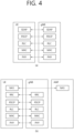
- FIG. 4 shows a radio protocol architecture, based on an embodiment of the present disclosure.
- the embodiment of FIG. 4 may be combined with various embodiments of the present disclosure.
- FIG. 4(a) shows a radio protocol architecture for a user plane
- FIG. 4(b) shows a radio protocol architecture for a control plane.
- the user plane corresponds to a protocol stack for user data transmission
- the control plane corresponds to a protocol stack for control signal transmission.
- a physical layer provides an upper layer with an information transfer service through a physical channel.
- the physical layer is connected to a medium access control (MAC) layer which is an upper layer of the physical layer through a transport channel.
- MAC medium access control
- Data is transferred between the MAC layer and the physical layer through the transport channel.
- the transport channel is classified according to how and with what characteristics data is transmitted through a radio interface.
- the physical channel is modulated using an orthogonal frequency division multiplexing (OFDM) scheme, and utilizes time and frequency as a radio resource.
- OFDM orthogonal frequency division multiplexing
- the MAC layer provides services to a radio link control (RLC) layer, which is a higher layer of the MAC layer, via a logical channel.
- RLC radio link control
- the MAC layer provides a function of mapping multiple logical channels to multiple transport channels.
- the MAC layer also provides a function of logical channel multiplexing by mapping multiple logical channels to a single transport channel.
- the MAC layer provides data transfer services over logical channels.
- the RLC layer performs concatenation, segmentation, and reassembly of Radio Link Control Service Data Unit (RLC SDU).
- RLC SDU Radio Link Control Service Data Unit
- TM transparent mode
- UM unacknowledged mode
- AM acknowledged mode
- An AM RLC provides error correction through an automatic repeat request (ARQ).
- a radio resource control (RRC) layer is defined only in the control plane.
- the RRC layer serves to control the logical channel, the transport channel, and the physical channel in association with configuration, reconfiguration and release of RBs.
- the RB is a logical path provided by the first layer (i.e., the physical layer or the PHY layer) and the second layer (i.e., the MAC layer, the RLC layer, and the packet data convergence protocol (PDCP) layer) for data delivery between the UE and the network.
- the first layer i.e., the physical layer or the PHY layer
- the second layer i.e., the MAC layer, the RLC layer, and the packet data convergence protocol (PDCP) layer
- Functions of a packet data convergence protocol (PDCP) layer in the user plane include user data delivery, header compression, and ciphering.
- Functions of a PDCP layer in the control plane include control-plane data delivery and ciphering/integrity protection.
- PDCP packet data convergence protocol
- SDAP service data adaptation protocol
- QoS Quality of Service
- DRB data radio bearer
- QFI QoS flow ID
- the configuration of the RB implies a process for specifying a radio protocol layer and channel properties to provide a particular service and for determining respective detailed parameters and operations.
- the RB can be classified into two types, i.e., a signaling RB (SRB) and a data RB (DRB).
- SRB signaling RB
- DRB data RB
- the SRB is used as a path for transmitting an RRC message in the control plane.
- the DRB is used as a path for transmitting user data in the user plane.
- an RRC_CONNECTED state When an RRC connection is established between an RRC layer of the UE and an RRC layer of the E-UTRAN, the UE is in an RRC_CONNECTED state, and, otherwise, the UE may be in an RRC_IDLE state.
- an RRC_INACTIVE state is additionally defined, and a UE being in the RRC_INACTIVE state may maintain its connection with a core network whereas its connection with the BS is released.
- Data is transmitted from the network to the UE through a downlink transport channel.
- the downlink transport channel include a broadcast channel (BCH) for transmitting system information and a downlink-shared channel (SCH) for transmitting user traffic or control messages. Traffic of downlink multicast or broadcast services or the control messages can be transmitted on the downlink-SCH or an additional downlink multicast channel (MCH).
- Data is transmitted from the UE to the network through an uplink transport channel.
- Examples of the uplink transport channel include a random access channel (RACH) for transmitting an initial control message and an uplink SCH for transmitting user traffic or control messages.
- RACH random access channel
- Examples of logical channels belonging to a higher channel of the transport channel and mapped onto the transport channels include a broadcast channel (BCCH), a paging control channel (PCCH), a common control channel (CCCH), a multicast control channel (MCCH), a multicast traffic channel (MTCH), etc.
- BCCH broadcast channel
- PCCH paging control channel
- CCCH common control channel
- MCCH multicast control channel
- MTCH multicast traffic channel
- the physical channel includes several OFDM symbols in a time domain and several sub-carriers in a frequency domain.
- One sub-frame includes a plurality of OFDM symbols in the time domain.
- a resource block is a unit of resource allocation, and consists of a plurality of OFDM symbols and a plurality of sub-carriers. Further, each subframe may use specific sub-carriers of specific OFDM symbols (e.g., a first OFDM symbol) of a corresponding subframe for a physical downlink control channel (PDCCH), i.e., an L1/L2 control channel.
- a transmission time interval (TTI) is a unit time of subframe transmission.
- FIG. 5 shows a structure of an NR system, based on an embodiment of the present disclosure.
- the embodiment of FIG. 5 may be combined with various embodiments of the present disclosure.
- a radio frame may be used for performing uplink and downlink transmission.
- Aradio frame has a length of 10ms and may be defined to be configured of two half-frames (HFs).
- a half-frame may include five 1ms subframes (SFs).
- a subframe (SF) may be divided into one or more slots, and the number of slots within a subframe may be determined based on subcarrier spacing (SCS).
- SCS subcarrier spacing
- Each slot may include 12 or 14 OFDM(A) symbols according to a cyclic prefix (CP).
- CP cyclic prefix
- each slot may include 14 symbols.
- each slot may include 12 symbols.
- a symbol may include an OFDM symbol (or CP-OFDM symbol) and a Single Carrier-FDMA (SC-FDMA) symbol (or Discrete Fourier Transform-spread-OFDM (DFT-s-OFDM) symbol).
- Table 1 shown below represents an example of a number of symbols per slot (N slot symb ), a number slots per frame (N frame,u slot ), and a number of slots per subframe (N subframe,u slot ) based on an SCS configuration (u), in a case where a normal CP is used.
- Table 2 shows an example of a number of symbols per slot, a number of slots per frame, and a number of slots per subframe based on the SCS, in a case where an extended CP is used.
- OFDM(A) numerologies e.g., SCS, CP length, and so on
- a (absolute time) duration (or section) of a time resource e.g., subframe, slot or TTI
- a time unit (TU) for simplicity
- multiple numerologies or SCSs for supporting diverse 5G services may be supported.
- an SCS is 15kHz
- a wide area of the conventional cellular bands may be supported, and, in case an SCS is 30kHz/60kHz a dense-urban, lower latency, wider carrier bandwidth may be supported.
- the SCS is 60kHz or higher, a bandwidth that is greater than 24.25GHz may be used in order to overcome phase noise.
- An NR frequency band may be defined as two different types of frequency ranges.
- the two different types of frequency ranges may be FR1 and FR2.
- the values of the frequency ranges may be changed (or varied), and, for example, the two different types of frequency ranges may be as shown below in Table 3.
- FR1 may mean a "sub 6GHz range”
- FR2 may mean an "above 6GHz range” and may also be referred to as a millimeter wave (mmW).
- mmW millimeter wave
- FR1 may include a band within a range of 410MHz to 7125MHz. More specifically, FR1 may include a frequency band of 6GHz (or 5850, 5900, 5925 MHz, and so on) and higher. For example, a frequency band of 6GHz (or 5850, 5900, 5925 MHz, and so on) and higher being included in FR1 mat include an unlicensed band. The unlicensed band may be used for diverse purposes, e.g., the unlicensed band for vehicle-specific communication (e.g., automated driving).
- SCS Corresponding frequency range Subcarrier Spacing
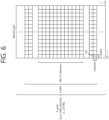
- FIG. 6 shows a structure of a slot of an NR frame, based on an embodiment of the present disclosure.
- the embodiment of FIG. 6 may be combined with various embodiments of the present disclosure.
- bandwidth part BWP
- carrier a bandwidth part (BWP) and a carrier
- the initial BWP may be given as a consecutive RB set for a remaining minimum system information (RMSI) control resource set (CORESET) (configured by physical broadcast channel (PBCH)).
- RMSI remaining minimum system information
- CORESET control resource set
- PBCH physical broadcast channel
- SIB system information block
- the default BWP may be configured by a higher layer.
- an initial value of the default BWP may be an initial DL BWP.
- DCI downlink control information
- the BWP may be defined for SL.
- the same SL BWP may be used in transmission and reception.
- a transmitting UE may transmit a SL channel or a SL signal on a specific BWP
- a receiving UE may receive the SL channel or the SL signal on the specific BWP.
- the SL BWP may be defined separately from a Uu BWP, and the SL BWP may have configuration signaling separate from the Uu BWP.
- the UE may receive a configuration for the SL BWP from the BS/network.
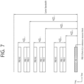
- FIG. 7 shows an example of a BWP, based on an embodiment of the present disclosure.
- the embodiment of FIG. 7 may be combined with various embodiments of the present disclosure. It is assumed in the embodiment of FIG. 7 that the number of BWPs is 3.
- a common resource block may be a carrier resource block numbered from one end of a carrier band to the other end thereof.
- the PRB may be a resource block numbered within each BWP.
- a point A may indicate a common reference point for a resource block grid.
- the BWP may be configured by a point A, an offset N start BWP from the point A, and a bandwidth N size BWP .
- the point A may be an external reference point of a PRB of a carrier in which a subcarrier 0 of all numerologies (e.g., all numerologies supported by a network on that carrier) is aligned.
- the offset may be a PRB interval between a lowest subcarrier and the point A in a given numerology.
- the bandwidth may be the number of PRBs in the given numerology.
- V2X or SL communication will be described.
- FIG. 8 shows a radio protocol architecture for a SL communication, based on an embodiment of the present disclosure.
- the embodiment of FIG. 8 may be combined with various embodiments of the present disclosure. More specifically, FIG. 8(a) shows a user plane protocol stack, and FIG. 8(b) shows a control plane protocol stack.
- SLSS sidelink synchronization signal
- the SLSS may include a primary sidelink synchronization signal (PSSS) and a secondary sidelink synchronization signal (SSSS), as a SL-specific sequence.
- PSSS primary sidelink synchronization signal
- SSSS secondary sidelink synchronization signal
- the PSSS may be referred to as a sidelink primary synchronization signal (S-PSS)
- S-SSS sidelink secondary synchronization signal
- S-SSS sidelink secondary synchronization signal
- length-127 M-sequences may be used for the S-PSS
- length-127 gold sequences may be used for the S-SSS.
- a UE may use the S-PSS for initial signal detection and for synchronization acquisition.
- the UE may use the S-PSS and the S-SSS for acquisition of detailed synchronization and for detection of a synchronization signal ID.
- a physical sidelink broadcast channel may be a (broadcast) channel for transmitting default (system) information which must be first known by the UE before SL signal transmission/reception.
- the default information may be information related to SLSS, a duplex mode (DM), a time division duplex (TDD) uplink/downlink (UL/DL) configuration, information related to a resource pool, a type of an application related to the SLSS, a subframe offset, broadcast information, or the like.
- DM duplex mode
- TDD time division duplex
- UL/DL uplink/downlink
- a payload size of the PSBCH may be 56 bits including 24-bit cyclic redundancy check (CRC).
- the S-PSS, the S-SSS, and the PSBCH may be included in a block format (e.g., SL synchronization signal (SS)/PSBCH block, hereinafter, sidelink-synchronization signal block (S-SSB)) supporting periodical transmission.
- the S-SSB may have the same numerology (i.e., SCS and CP length) as a physical sidelink control channel (PSCCH)/physical sidelink shared channel (PSSCH) in a carrier, and a transmission bandwidth may exist within a (pre-)configured sidelink (SL) BWP.
- the S-SSB may have a bandwidth of 11 resource blocks (RBs).
- the PSBCH may exist across 11 RBs.
- a frequency position of the S-SSB may be (pre-)configured. Accordingly, the UE does not have to perform hypothesis detection at frequency to discover the S-SSB in the carrier.
- FIG. 9 shows a UE performing V2X or SL communication, based on an embodiment of the present disclosure.
- the embodiment of FIG. 9 may be combined with various embodiments of the present disclosure.
- the term 'UE' may generally imply a UE of a user.
- the BS may also be regarded as a sort of the UE.
- a UE 1 may be a first apparatus 100
- a UE 2 may be a second apparatus 200.
- the UE 1 may select a resource unit corresponding to a specific resource in a resource pool which implies a set of series of resources.
- the UE 1 may transmit a SL signal by using the resource unit.
- a resource pool in which the UE 1 is capable of transmitting a signal may be configured to the UE 2 which is a receiving UE, and the signal of the UE 1 may be detected in the resource pool.
- the BS may inform the UE 1 of the resource pool. Otherwise, if the UE 1 is out of the connectivity range of the BS, another UE may inform the UE 1 of the resource pool, or the UE 1 may use a pre-configured resource pool.
- the resource pool may be configured in unit of a plurality of resources, and each UE may select a unit of one or a plurality of resources to use it in SL signal transmission thereof.
- FIG. 10 shows a procedure of performing V2X or SL communication by a UE based on a transmission mode, based on an embodiment of the present disclosure.
- the transmission mode may be called a mode or a resource allocation mode.
- the transmission mode may be called an LTE transmission mode.
- the transmission mode may be called an NR resource allocation mode.
- FIG. 10(a) shows a UE operation related to an LTE transmission mode 1 or an LTE transmission mode 3.
- FIG. 10(a) shows a UE operation related to an NR resource allocation mode 1.
- the LTE transmission mode 1 may be applied to general SL communication
- the LTE transmission mode 3 may be applied to V2X communication.
- FIG. 10(b) shows a UE operation related to an LTE transmission mode 2 or an LTE transmission mode 4.
- FIG. 10(b) shows a UE operation related to an NR resource allocation mode 2.
- a BS may schedule a SL resource to be used by the UE for SL transmission.
- the BS may perform resource scheduling to a UE 1 through a PDCCH (more specifically, downlink control information (DCI)), and the UE 1may perform V2X or SL communication with respect to a UE 2 according to the resource scheduling.
- the UE 1 may transmit a sidelink control information (SCI) to the UE 2 through a physical sidelink control channel (PSCCH), and thereafter transmit data based on the SCI to the UE 2 through a physical sidelink shared channel (PSSCH).
- SCI sidelink control information
- PSCCH physical sidelink control channel
- PSSCH physical sidelink shared channel
- the UE may determine a SL transmission resource within a SL resource configured by a BS/network or a pre-configured SL resource.
- the configured SL resource or the pre-configured SL resource may be a resource pool.
- the UE may autonomously select or schedule a resource for SL transmission.
- the UE may perform SL communication by autonomously selecting a resource within a configured resource pool.
- the UE may autonomously select a resource within a selective window by performing a sensing and resource (re)selection procedure.
- the sensing may be performed in unit of subchannels.
- the UE 1 which has autonomously selected the resource within the resource pool may transmit the SCI to the UE 2 through a PSCCH, and thereafter may transmit data based on the SCI to the UE 2 through a PSSCH.
- FIG. 11 shows three cast types, based on an embodiment of the present disclosure.
- the embodiment of FIG. 11 may be combined with various embodiments of the present disclosure.
- FIG. 11(a) shows broadcast-type SL communication
- FIG. 11(b) shows unicast type-SL communication
- FIG. 11(c) shows groupcast-type SL communication.
- a UE may perform one-to-one communication with respect to another UE.
- the UE may perform SL communication with respect to one or more UEs in a group to which the UE belongs.
- SL groupcast communication may be replaced with SL multicast communication, SL one-to-many communication, or the like.
- HARQ hybrid automatic repeat request
- An error compensation scheme is used to secure communication reliability.
- Examples of the error compensation scheme may include a forward error correction (FEC) scheme and an automatic repeat request (ARQ) scheme.
- FEC forward error correction
- ARQ automatic repeat request
- the FEC scheme errors in a receiving end are corrected by attaching an extra error correction code to information bits.
- the FEC scheme has an advantage in that time delay is small and no information is additionally exchanged between a transmitting end and the receiving end but also has a disadvantage in that system efficiency deteriorates in a good channel environment.
- the ARQ scheme has an advantage in that transmission reliability can be increased but also has a disadvantage in that a time delay occurs and system efficiency deteriorates in a poor channel environment.
- a hybrid automatic repeat request (HARQ) scheme is a combination of the FEC scheme and the ARQ scheme.
- HARQ scheme it is determined whether an unrecoverable error is included in data received by a physical layer, and retransmission is requested upon detecting the error, thereby improving performance.
- HARQ feedback and HARQ combining in the physical layer may be supported.
- the receiving UE may receive the PSSCH from a transmitting UE, and the receiving UE may transmit HARQ feedback for the PSSCH to the transmitting UE by using a sidelink feedback control information (SFCI) format through a physical sidelink feedback channel (PSFCH).
- SFCI sidelink feedback control information
- PSFCH physical sidelink feedback channel
- the SL HARQ feedback may be enabled for unicast.
- a non-code block group non-CBG
- the receiving UE may generate HARQ-ACK.
- the receiving UE may transmit the HARQ-ACK to the transmitting UE.
- the receiving UE may transmit HARQ-NACK to the transmitting UE.
- the SL HARQ feedback may be enabled for groupcast.
- two HARQ feedback options may be supported for groupcast.
- the receiving UE may transmit HARQ feedback for the PSSCH to the transmitting UE. Otherwise, if the TX-RX distance is greater than the communication range requirement, the receiving UE may not transmit the HARQ feedback for the PSSCH to the transmitting UE.
- the transmitting UE may inform the receiving UE of a location of the transmitting UE through SCI related to the PSSCH.
- the SCI related to the PSSCH may be second SCI.
- TDM between the PSCCH/PSSCH and the PSFCH may be allowed for a PSFCH format for SL in a slot.
- a sequence-based PSFCH format having a single symbol may be supported.
- the single symbol may not an AGC duration.
- the sequence-based PSFCH format may be applied to unicast and groupcast.
- the receiving UE may transmit HARQ feedback for the PSSCH to the transmitting UE in a slot #(N+A).
- the slot #(N+A) may include a PSFCH resource.
- A may be a smallest integer greater than or equal to K.
- K may be the number of logical slots. In this case, K may be the number of slots in a resource pool. Alternatively, for example, K may be the number of physical slots. In this case, K may be the number of slots inside or outside the resource pool.
- the receiving UE may determine a frequency domain and/or code domain of the PSFCH resource based on an implicit mechanism in a configured resource pool. For example, the receiving UE may determine the frequency domain and/or code domain of the PSFCH resource, based on at least one of a slot index related to PSCCH/PSSCH/PSFCH, a sub-channel related to PSCCH/PSSCH, and/or an identifier for identifying each receiving UE in a group for HARQ feedback based on the groupcast option 2. Additionally/alternatively, for example, the receiving UE may determine the frequency domain and/or code domain of the PSFCH resource, based on at least one of SL RSRP, SINR, L1 source ID, and/or location information.
- the UE may select any one of HARQ feedback transmission through the PSFCH and HARQ feedback reception through the PSFCH based on a priority rule.
- the priority rule may be based on at least priority indication of the related PSCCH/PSSCH.
- the UE may select specific HARQ feedback transmission based on the priority rule.
- the priority rule may be based on at least priority indication of the related PSCCH/PSSCH.
- a transmitting UE may be a UE which transmits data to a (target) receiving UE (RX UE).
- the TX UE may be a UE which performs PSCCH transmission and/or PSSCH transmission.
- the TX UE may be a UE which transmits SL CSI-RS(s) and/or a SL CSI report request indicator to the (target) RX UE.
- the TX UE may be a UE which transmits (pre-defined) reference signal(s) (e.g., PSSCH demodulation reference signal (DM-RS)) and/or a SL (L1) RSRP report request indicator, to the (target) RX UE, to be used for SL (L1) RSRP measurement.
- the TX UE may be a UE which transmits a (control) channel (e.g., PSCCH, PSSCH, etc.) and/or reference signal(s) on the (control) channel (e.g., DM-RS, CSI-RS, etc.), to be used for a SL RLM operation and/or a SL RLF operation of the (target) RX UE.
- a (control) channel e.g., PSCCH, PSSCH, etc.
- reference signal(s) on the (control) channel e.g., DM-RS, CSI-RS, etc.
- a receiving UE may be a UE which transmits SL HARQ feedback to a transmitting UE (TX UE) based on whether decoding of data received from the TX UE is successful and/or whether detection/decoding of a PSCCH (related to PSSCH scheduling) transmitted by the TX UE is successful.
- the RX UE may be a UE which performs SL CSI transmission to the TX UE based on SL CSI-RS(s) and/or a SL CSI report request indicator received from the TX UE.
- the first SCI including a first SCI configuration field group may be referred to as a 1 st SCI or 1 st -stage SCI
- the second SCI including a second SCI configuration field group may be referred to as a 2 nd SCI or 2 nd -stage SCI.
- the first SCI may be transmitted through a PSCCH.
- the second SCI may be transmitted through a (independent) PSCCH.
- the second SCI may be piggybacked and transmitted together with data through a PSSCH.
- a channel may be replaced/substituted with a signal, or vice versa.
- transmission/reception of a channel may include transmission/reception of a signal.
- transmission/reception of a signal may include transmission/reception of a channel.
- cast may be replaced/substituted with at least one of unicast, groupcast, and/or broadcast, or vice versa.
- a cast type may be replaced/substituted with at least one of unicast, groupcast, and/or broadcast, or vice versa.
- a resource may be replaced/substituted with a slot or a symbol, or vice versa.
- the resource may include a slot and/or a symbol.
- a (physical) channel used when a RX UE transmits at least one of the following information to a TX UE may be referred to as a PSFCH.
- a PSSCH slot related to a PSFCH resource may be replaced/substituted with a PSSCH slot related to a PUCCH resource, or vice versa.
- a PSCCH slot related to a PSFCH resource may be replaced/substituted with a PSCCH slot related to a PUCCH resource, or vice versa.
- a Uu channel may include a UL channel and/or a DL channel.
- the UL channel may include a PUSCH, a PUCCH, a sounding reference Signal (SRS), etc.
- the DL channel may include a PDCCH, a PDSCH, a PSS/SSS, etc.
- a SL channel may include a PSCCH, a PSSCH, a PSFCH, a PSBCH, a PSSS/SSSS, etc.
- sidelink information may include at least one of a sidelink message, a sidelink packet, a sidelink service, sidelink data, sidelink control information, and/or a sidelink transport block (TB).
- sidelink information may be transmitted through a PSSCH and/or a PSCCH.
- the MODE 1 TX UE may be allocated additional retransmission resource(s) for the RX UE by receiving a DCI from the base station.
- the SL HARQ feedback information may be HARQ feedback information reported by the RX UE to the MODE 1 TX UE.
- the MODE 1 TX UE may report the SL HARQ feedback information to the base station through a pre-configured PUCCH resource.
- the MODE 1 TX UE may be allocated additional retransmission resource(s) for the RX UE through a DCI from the base station.
- the DCI may include a MODE 1 dynamic grant (DG).
- the MODE 1 TX UE may perform transmission by using transmission resource(s) allocated by (specific) MODE 1 configured grant (CG) or MODE 1 dynamic grant (DG).
- the signaling/configuration may be signalled/configured by the base station.
- the signaling or the configuration may be signalled/configured through a field in a DCI received from the base
- the MODE 1 TX UE does not transmit a PSSCH and/or a PSCCH to the RX UE, there may be an ambiguous problem of which information the MODE 1 TX UE should report to the base station through a (pre-configured) PUCCH resource.
- a method for determining, by the MODE 1 TX UE, information transmitted to the base station through a PUCCH resource and an apparatus supporting the same are proposed.
- whether all or part of the following proposed methods or rules is applied may be configured specifically for a resource pool, a service type, a cast type, a groupcast HARQ feedback option, a destination UE, a (L1 or L2) destination (or source) ID, and/or a QoS parameter.
- the cast type may be unicast or groupcast.
- the groupcast HARQ feedback option may be the groupcast option 1 or the groupcast option 2.
- FIG. 12 shows a procedure in which a MODE 1 TX UE reports information on SL HARQ feedback to a base station, based on an embodiment of the present disclosure.
- the embodiment of FIG. 12 may be combined with various embodiments of the present disclosure.
- the MODE 1 TX UE may receive, from the base station through one or more MODE 1 grants, information on PSSCH and/or PSCCH resource scheduling in one or more PSSCH slots related to a PSFCH slot.
- the MODE 1 grant may include a MODE 1 DG or a DCI related to the MODE 1 DG.
- the MODE 1 grant may include a MODE 1 CG or a DCI related to the MODE 1 CG.
- the MODE 1 grant may include a combination of the MODE 1 DG and the MODE 1 CG.
- the DCI related to the MODE 1 CG may be a DCI for activating CG resource(s).
- the MODE 1 TX UE may perform sidelink transmission through a PSSCH and/or a PSCCH. For example, based on the information on PSSCH and/or PSCCH resource scheduling in one or more PSSCH slots related to the PSFCH slot, the MODE 1 TX UE may perform sidelink transmission through the PSSCH and/or the PSCCH.
- step S 1230 the MODE 1 TX UE may receive SL HARQ feedback from the RX UE through the PSFCH.
- the MODE 1 TX UE may report information on SL HARQ feedback to the base station.
- the MODE 1 TX UE may report information on SL HARQ feedback to the base station, based on various embodiments of the present disclosure.
- the information on SL HARQ feedback may be one of ACK or NACK/DTX.
- the MODE 1 TX UE may stop or omit a reporting operation of information on SL HARQ feedback, or may not report information on SL HARQ feedback, based on various embodiments of the present disclosure.
- the MODE 1 TX UE may determine whether or not to transmit a PUCCH to the base station and/or information to be transmitted to the base station through a (pre-configured) PUCCH resource, based on all or part of the methods/rules proposed in the present disclosure. For example, all or part of the methods/rules proposed in the present disclosure may be applied only for PSSCH and/or PSCCH transmission slot(s) in which a SL HARQ feedback operation of the RX UE is enabled, through pre-defined signaling by the base station, among a plurality of PSSCH and/or PSCCH transmission slots related to a PSFCH resource.
- all or part of the methods/rules proposed in the present disclosure may be applied only for PSSCH and/or PSCCH transmission slot(s) in which PUCCH-based SL HARQ feedback information reporting of the MODE 1 TX UE is enabled, through pre-defined signaling by the base station, among a plurality of PSSCH and/or PSCCH transmission slots related to a PSFCH resource.
- all or part of the methods/rules proposed in the present disclosure may be applied only for PSSCH and/or PSCCH transmission slot(s) in which a PUCCH resource for reporting SL HARQ feedback information of the MODE 1 TX UE is configured, through pre-defined signaling by the base station, among a plurality of PSSCH and/or PSCCH transmission slots related to a PSFCH resource.
- the pre-defined signaling may be signaling through a DCI including a MODE 1 CG or a MODE 1 DG.
- whether or not all or part of the methods/rules proposed in the present disclosure is applied may be configured differently based on the number of PSSCH and/or PSCCH transmission slots related to a PSFCH resource.
- whether or not all or part of the methods/rules proposed in the present disclosure is applied may be configured differently based on whether or not a semi-static SL HARQ codebook is configured. Specifically, for example, if the semi-static SL HARQ codebook is configured, and if the number of PSSCH and/or PSCCH transmission slots related to the PSFCH resource is set to M, the RX UE may transmit M-bit SL HARQ feedback to the MODE 1 TX UE, regardless of the number of (new) TBs actually received from the MODE 1 TX UE.
- the RX UE may transmit M-bit SL HARQ feedback to the MODE 1 TX UE, regardless of the number of PSSCHs and/or PSCCHs actually received from the MODE 1 TX UE.
- the MODE 1 TX UE may perform (PUCCH) transmission through a PUCCH resource related to the PSFCH resource or the PSSCH/PSCCH transmission slots.
- TB e.g., PSSCH and/or PSCCH
- a pre-configured threshold number of times e.g., one
- the MODE 1 TX UE may perform (PUCCH) transmission through a PUCCH resource related to the PSFCH resource or the PSSCH/PSCCH transmission slots.
- the MODE 1 TX UE may configure/generate SL HARQ feedback information related to PSSCH and/or PSCCH transmission slot(s) in which (new) TB transmission is not actually performed as ACK, the MODE 1 TX UE may report the ACK to the base station through the PUCCH resource.
- the MODE 1 TX UE may configure/generate SL HARQ feedback information related to the (new) TB (e.g., PSSCH and/or PSCCH) transmission as ACK, and the MODE 1 TX UE may report the ACK to the base station through the PUCCH resource.
- the (new) TB e.g., PSSCH and/or PSCCH
- the MODE 1 TX UE may receive information related to the groupcast option 2 from the base station through a MODE 1 CG and/or a MODE 1 DG.
- the MODE 1 TX UE may receive information related to the groupcast option 2 enabled through the MODE 1 CG and/or the MODE 1 DG from the base station.
- the MODE 1 TX UE may transmit a confirmation message to the base station.
- the confirmation message may be transmitted based on a MAC CE.
- the confirmation message may include information related to whether or not the MODE 1 TX UE has successfully received the DCI related to the MODE 1 CG.
- the base station transmits the DCI related to the MODE 1 DG to the MODE 1 TX UE, it may be difficult for the base station to determine whether or not the MODE 1 TX UE has successfully received the DCI. Specifically, for example, if the MODE 1 TX UE does not transmit a PUCCH to the base station, it may be difficult for the base station to distinguish whether (i) the MODE 1 TX UE does not perform PUCCH transmission because it fails to receive a DCI related to a MODE 1 DG or (ii) the MODE 1 TX UE does not perform PUCCH transmission because it does not perform (new) TB (e.g., PSSCH and/or PSCCH) transmission to the RX UE. In consideration of this, for example, different rules may be applied depending on whether the MODE 1 TX UE receives a DCI related to a MODE 1 CG or a DCI related to a MODE 1 DG from the base station.
- TB e.g., PSSCH and
- the MODE 1 TX UE may perform (PUCCH) transmission through a PUCCH resource related to the PSFCH resource or the PSSCH/PSCCH transmission slots.
- TB e.g., PSSCH and/or PSCCH
- a pre-configured threshold number of times e.g., one
- the MODE 1 TX UE may perform (PUCCH) transmission through a PUCCH resource related to the PSFCH resource or the PSSCH/PSCCH transmission slots.
- the MODE 1 TX UE may configure/generate SL HARQ feedback information related to PSSCH and/or PSCCH transmission slot(s) in which (new) TB transmission is not actually performed as ACK, the MODE 1 TX UE may report the ACK to the base station through the PUCCH resource.
- the MODE 1 TX UE may perform (PUCCH) transmission through a PUCCH resource related to the PSFCH resource or the PSSCH/PSCCH transmission slots.
- TB e.g., PSSCH and/or PSCCH
- a pre-configured threshold number of times e.g., one
- the MODE 1 TX UE may perform (PUCCH) transmission through a PUCCH resource related to the PSFCH resource or the PSSCH/PSCCH transmission slots.
- the MODE 1 TX UE may configure/generate SL HARQ feedback information related to PSSCH and/or PSCCH transmission slot(s) in which (new) TB transmission is not actually performed as NACK/DTX, the MODE 1 TX UE may report the NACK/DTX to the base station through the PUCCH resource.
- the MODE 1 TX UE may perform (PUCCH) transmission through a PUCCH resource related to the PSFCH resource or the PSSCH/PSCCH transmission slots.
- TB e.g., PSSCH and/or PSCCH
- the MODE 1 TX UE may perform (PUCCH) transmission through a PUCCH resource related to the PSFCH resource or the PSSCH/PSCCH transmission slots.
- the MODE 1 TX UE may perform (PUCCH) transmission through a PUCCH resource related to the PSFCH resource or the PSSCH/PSCCH transmission slots.
- TB e.g., PSSCH and/or PSCCH
- a pre-configured threshold number of times e.g., one
- the MODE 1 TX UE may perform (PUCCH) transmission through a PUCCH resource related to the PSFCH resource or the PSSCH/PSCCH transmission slots.
- the MODE 1 TX UE may configure/generate SL HARQ feedback information related to PSSCH and/or PSCCH transmission slot(s) in which (new) TB transmission is not actually performed as ACK, the MODE 1 TX UE may report the ACK to the base station through the PUCCH resource.
- the MODE 1 TX UE may perform (PUCCH) transmission through a PUCCH resource related to the PSFCH resource or the PSSCH/PSCCH transmission slots.
- TB e.g., PSSCH and/or PSCCH
- a pre-configured threshold number of times e.g., one
- the MODE 1 TX UE may perform (PUCCH) transmission through a PUCCH resource related to the PSFCH resource or the PSSCH/PSCCH transmission slots.
- the MODE 1 TX UE may configure/generate SL HARQ feedback information related to PSSCH and/or PSCCH transmission slot(s) in which (new) TB transmission is not actually performed as NACK/DTX, the MODE 1 TX UE may report the NACK/DTX to the base station through the PUCCH resource.
- the MODE 1 TX UE may not perform PUCCH transmission.
- FIG. 13 shows a procedure for a MODE 1 TX UE to report information on SL HARQ feedback to a base station, based on an embodiment of the present disclosure.
- the embodiment of FIG. 13 may be combined with various embodiments of the present disclosure.
- the TX UE may receive, from the base station, information related to SL resource(s) and information related to a PUCCH resource.
- the TX UE may transmit, to the RX UE, a MAC PDU for which HARQ feedback is disabled based on the SL resource(s). For example, retransmission of the MAC PDU may not be required.
- the TX UE may generate ACK information related to the transmission of the MAC PDU for which HARQ feedback is disabled.
- the TX UE may transmit, to the base station, ACK information based on the PUCCH resource.
- the K1 value needs to be large enough to accommodate all the processing times for PSCCH, PSSCH, and PSFCH transmission.
- a slot containing PSCCH or PSSCH can be a reference point.
- K1 is defined as gap from a slot containing PSCCH or PSSCH to a slot containing PUCCH.
- the K1 value is smaller than that of the first case above. It's necessary that the K1 value is determined to accommodate the processing time for PSSCH and/or PSFCH transmissions.
- TX UE may not know HARQ states of PSSCH when it does not receive the associated PSFCH from the RX UE.
- a slot containing PSFCH can be a reference point.
- K1 is defined as slot gap from a slot containing PSFCH to a slot containing PUCCH.
- TX UE After receiving PSFCH, TX UE can decide PUCCH timing for SL HARQ feedback report to gNB.
- the reference point for the PUCCH transmission timing is the slot where the TX UE receives PSFCH associated with PSSCH transmission(s) indicated by the DCI.
- numerologies of PDCCH, SL channels, and PUCCH could be different. In this case, principles used in NR Uu link could be reused.
- a slot offset between PSFCH reception and corresponding PUCCH transmission may be configured for the UE through RRC signaling.
- the numerology of the indicated slot offset may be the same as the numerology of the PUCCH.
- the slot offset 0 may represent the latest slot overlapping with PSFCH reception.
- the UE may report HARQ feedback to the base station based on Table 6 and/or Table 7.
- Table 6 Alternatively, if simultaneous transmission of SL HARQ feedback report and DL HARQ feedback on the same PUCCH needs to be supported, the concept of virtual DAI and PDSCH can be introduced.
- SL DCI can indicate virtual DAI and PDSCH, and the virtual PDSCH can be a reference point.
- Using virtual DAI and PDSCH enables to reuse existing DL HARQ feedback multiplexing scheme including SL HARQ feedback report.
- UE expects to report the SL HARQ feedback on reception of a single PSFCH with a single codebook.
- multiple SL HARQ feedbacks associated with more than one PSFCH will not be transmitted simultaneously on the same PUCCH.
- gNB will schedule retransmission resource after receiving SL HARQ feedback on PUCCH, it would not be beneficial to postpone SL HARQ feedback reporting to gNB.
- SL HARQ feedback of more than one PSSCH transmissions scheduled by different PDCCHs are transmitted on the same PSFCH.
- the PUCCH transmission timing indicated by different PDCCHs will be the same considering the reference point for the transmission timing is slot containing PSFCH resource.
- a single PUCCH resource only carries all the SL HARQ feedbacks received on a single PSFCH slot from a single TX UE point of view.
- [Table 7] A simple approach of multiplexing SL HARQ feedback report and DL HARQ feedback is to guarantee time-multiplexed transmission between the two feedbacks. That is, it's not expected they are transmitted on same PUCCH resources at given time.
- This approach has pros and cons: It does not require any specification modification on DL HARQ feedback scheme. But it may require SL HARQ feedback report can be postponed when conflicted with DL HARQ feedback timing, thus increase the latency of the SL HARQ feedback report. In addition it may restrict flexibility in scheduling feedback timing to some extent.
- HARQ feedback on DL SPS or SL configured grant may cause dropping SL HARQ feedback report as the relevant HARQ feedback timing and PUCCH resource allocation cannot be dynamically changed.
- Another approach is to support simultaneous transmission of SL HARQ feedback report and DL HARQ feedback in same slot.
- the order of HARQ-ACK bits is determined based DAI and K0 (slot offset between PDCCH and PDSCH), it is necessary to define reference or virtual DAI together with virtual PDSCH for PDCCH scheduling NR SL resources.
- K0 slot offset between PDCCH and PDSCH
- symbols for PDCCH and PDSCH transmission is not used for uplink, it needs to ensure that all the symbols associated with the virtual PDSCH are not used for uplink or sidelink.
- the number of PSSCH slots associated with the same PSFCH slot is N, and if a TX UE transmits multiple PSSCHs across N slots to the N RX UEs, the TX UE will receive N PSFCHs from the N RX UEs. In this case, the number of reserved bits for SL HARQ feedback can be decided as N. 2) If a TX UE transmits multiple PSSCHs with N TBs across N slots to one RX UE, the TX UE will receive one PSFCH with N bits of SL HARQ feedbacks from the RX UE. In this case, the number of reserved bits for SL HARQ feedback can be decided as N.
- a TX UE transmits multiple PSSCHs with a TB across N slots to one RX UE, the TX UE will receive one bit of SL HARQ feedback from the RX UE. In this case, the TX UE extends the received one bit into N bits, and the number of reserved bits for SL HARQ feedback can be decided as N.
- Proposal In Rel-16 NR sidelink, support only TDMed transmission between SL HARQ feedback and DL HARQ feedback.
- Proposal When DL HARQ feedback and SL HARQ feedback occur in the same timing, TX UE select one type of HARQ feedback.
- the UE may report HARQ feedback to the base station based on Table 8.
- Table 8 In NR sidelink, depending on the cast type and/or HARQ feedback option, the interpretation of "no PSFCH" could be different. In case of broadcast, regardless of whether RX UE succeeds or fails to decode PSSCH, no PSFCH will be transmitted by the RX UE. On the other hand, in case of unicast and groupcast, when the RX UE fails to detect SCI (including both 1 st stage and 2 nd stage), no PSFCH is transmitted by the RX UE.
- no PSFCH is transmitted if the RX UE succeeds to decode PSSCH or RX UE fails to detect SCI.
- any resources can be used broadcast, unicast, groupcast with Option 1, or groupcast with Option2.
- TX UE needs to construct HARQ feedbacks to be reported to gNB properly since at least TX UE knows which cast type and/or HARQ feedback option are used for the scheduled SL resources. Basically, when TX UE fails to detect DCI scheduling SL resources, no PUCCH will be transmitted.
- gNB can transmit PDCCH again to allocate SL resources.
- TX UE succeeds DCI decoding, and if RX UE fails to detect SCI, PSFCH will not be transmitted by the RX UE regardless of cast type and HARQ feedback Option.
- TX UE knows the cast type and HARQ feedback Option, it can decide HARQ states of PSSCH to be reported to gNB. For instance, for unicast and groupcast with Option 2, TX UE can transmit NACK on PUCCH. In this case, gNB can allocate SL resources to enhance detection performance of PSCCH and/or PSSCH. For groupcast Option 1, TX UE may not distinguish whether RX UE succeeds to decode PSSCH or fails to decode SCI.
- the TX UE may transmit ACK on PUCCH, which may cause DTX problem.
- TX UE succeeds DCI decoding, and if RX UE succeeds to detect SCI, TX UE can forward SL HARQ feedback received on a PSFCH for unicast or groupcast with Option 2.
- TX UE will transmit NACK on PUCCH if at least one NACK on PSFCH is received. Otherwise, TX UE will transmit ACK on PUCCH. Meanwhile, HARQ feedback on PSFCH could be disabled including broadcast case.
- TX UE transmits ACK on PUCCH for PSSCH transmissions without HARQ feedback on PSFCH to avoid that gNB schedules additional SL resources unnecessarily.
- configured grant TX UE may or may not transmit PSCCH/PSSCH to RX UE(s). In this case, if the TX UE transmit PUCCH for every configured SL resources, control overhead would be large.
- the TX UE reports nothing to gNB when the TX UE transmits no PSCCH/PSSCH on the configured SL resources.
- gNB would use the reported ACK or NACK for the actual PSSCH transmissions.
- the ratio of PSSCH DTX on the configured SL resources is reported to gNB, it would be beneficial to manage the configured SL resources more efficiently.
- - TX UE sets ACK state for a scheduled/configured PSSCH resource if the TX UE receives ACK on PSFCH(s) only for the PSSCH transmitted on the scheduled/configured PSSCH resource by the TX UE.
- - TX UE sets DTX state for a scheduled/configured PSSCH resource if the TX UE transmits no PSSCH on the scheduled/configured PSSCH resource.
- - TX UE sets ACK state for a scheduled/configured PSSCH resource if the TX UE receives no PSFCH for the PSSCH transmitted on the scheduled/configured PSSCH resource by the TX UE.
- - TX UE sets DTX state for a scheduled/configured PSSCH resource if the TX UE transmits no PSSCH on the scheduled/configured PSSCH resource.
- the UE may report HARQ feedback to the base station based on Table 9.
- Table 9 Considering blind retransmission, DCI and SCI can schedule more than one PSSCH transmissions for a TB. Meanwhile, it is necessary to decide how many SL HARQ feedback will be transmitted for a TB. To be specific, it can be considered that the RX UE transmits SL HARQ feedback of each PSSCH transmission of a TB. In this case, it is possible that parts of retransmission resources are released when the TX UE receives ACK on PSFCH for a TB.
- the RX UE transmits ACK on PSFCH
- the RX UE expects no PSSCH on the remaining retransmission resource(s) indicated by a SCI and SL HARQ feedback for the remaining PSSCH resources will not be transmitted.
- SL HARQ feedback on PUCCH can be transmitted for every PSSCH transmissions indicated by a SCI/DCI for a TB.
- signaling overhead to indicate multiple PUCCH resources and their timing would be large.
- the processing time would not be sufficient to transmit/receive PSFCH and PUCCH.
- DCI includes only one set of PUCCH resource and its timing.
- RX UE will transmit SL HARQ feedback once after the last PSSCH transmission indicated by a SCI for a TB. It is assumed that all the PSSCH resources indicated by a SCI for a TB will be always used even though the RX UE succeeds to decode PSSCH on the first resource. In this case, the TX UE will transmit SL HARQ feedback on PUCCH once for multiple PSSCH transmissions indicated by a SCI/DCI for a TB.
- SL HARQ feedback on PUCCH is transmitted for each PSSCH transmission indicated by a SCI/DCI for a TB, it can cause signaling overhead for timing and PUCCH resource indications.
- Proposal Whether SL HARQ feedback on PUCCH is transmitted for each PSSCH transmission indicated by a SCI/DCI for a TB is determined by RRC configuration.
- FIG. 14 shows a method for a first device to report SL HARQ feedback to a base station, based on an embodiment of the present disclosure.
- the embodiment of FIG. 14 may be combined with various embodiments of the present disclosure.
- the first device may receive a MODE 1 grant from the base station.
- the MODE 1 grant may include at least one of a MODE 1 dynamic grant DCI and/or a MODE 1 configured grant DCI.
- the MODE 1 grant may include information on PSSCH and/or PSCCH resource scheduling in one or more PSSCH slots related to a PSFCH slot and information on a PUCCH resource for reporting information on SL HARQ feedback received in the PSFCH slot.
- the PUCCH resource may be allocated to the first device.
- the first device may transmit information on SL HARQ feedback to the base station. For example, based on the MODE 1 dynamic grant or the MODE 1 configured grant, the first device may determine information on SL HARQ feedback and/or whether or not to transmit information on SL HARQ feedback to the base station by using the PUCCH resource. For example, the first device may determine information on SL HARQ feedback and/or whether or not to transmit information on SL HARQ feedback to the base station by using the PUCCH resource, based on various embodiments of the present disclosure. For example, the information on SL HARQ feedback may be at least one of ACK, NACK, and/or DTX.
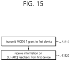
- FIG. 15 shows a method for a base station to receive SL HARQ feedback from a first device, based on an embodiment of the present disclosure.
- the embodiment of FIG. 15 may be combined with various embodiments of the present disclosure.
- the base station may transmit a MODE 1 grant to the first device.
- the MODE 1 grant may include at least one of a MODE 1 dynamic grant DCI and/or a MODE 1 configured grant DCI.
- the MODE 1 grant may include information on PSSCH and/or PSCCH resource scheduling in one or more PSSCH slots related to a PSFCH slot and information on a PUCCH resource for reporting information on SL HARQ feedback received in the PSFCH slot.
- the PUCCH resource may be allocated to the first device.
- the base station may receive information on SL HARQ feedback from the first device. For example, based on the MODE 1 dynamic grant or the MODE 1 configured grant, information on SL HARQ feedback and/or whether or not to transmit information on SL HARQ feedback to the base station by using the PUCCH resource may be determined by the first device. For example, information on SL HARQ feedback and/or whether or not to transmit information on SL HARQ feedback to the base station by using the PUCCH resource may be determined by the first device, based on various embodiments of the present disclosure. For example, the information on SL HARQ feedback may be at least one of ACK, NACK, and/or DTX.
- FIG. 16 shows a method for a first device to perform wireless communication, based on an embodiment of the present disclosure.
- the embodiment of FIG. 16 may be combined with various embodiments of the present disclosure.
- the ACK related to the transmission of the MAC PDU may be generated by the first device, based on the HARQ feedback being disabled for the MAC PDU.
- the ACK related to the transmission of the MAC PDU may be generated by the first device, based on retransmission of the MAC PDU not being required.
- the first device may determine a physical sidelink feedback channel (PSFCH) resource based on a slot index of a physical sidelink shared channel (PSSCH) resource and a subchannel index of the PSSCH resource.
- the SL resource may include a physical sidelink control channel (PSCCH) resource and the PSSCH resource.
- the information related to the PUCCH resource may include information related to a slot offset between the PUCCH resource and the PSFCH resource, and the PUCCH resource may be included in a slot after the slot offset from a slot including the PSFCH resource.
- the HARQ feedback for the MAC PDU may not be transmitted on the PSFCH resource by the second device, based on the HARQ feedback being disabled for the MAC PDU.
- the first device may transmit, to the second device through a PSSCH, a sidelink control information (SCI) including HARQ feedback disabled information representing disabling of the HARQ feedback for the MAC PDU.
- SCI sidelink control information
- the HARQ feedback for the MAC PDU may not be transmitted by the second device, based on the HARQ feedback disabled information.
- the processor 102 of the first device 100 may control the transceiver 106 to receive, from a base station, information related to a sidelink (SL) resource and information related to a physical uplink control channel (PUCCH) resource.
- the processor 102 of the first device 100 may control the transceiver 106 to transmit, to a second device, a medium access control (MAC) packet data unit (PDU) for which hybrid automatic repeat request (HARQ) feedback is disabled, based on the SL resource.
- the processor 102 of the first device 100 may generate ACK related to transmission of the MAC PDU for which the HARQ feedback is disabled.
- the processor 102 of the first device 100 may control the transceiver 106 to transmit, to the base station, the ACK based on the PUCCH resource.
- a first device configured to perform wireless communication may be provided.
- the first device may comprise: one or more memories storing instructions; one or more transceivers; and one or more processors connected to the one or more memories and the one or more transceivers.
- the one or more processors may execute the instructions to: receive, from a base station, information related to a sidelink (SL) resource and information related to a physical uplink control channel (PUCCH) resource; transmit, to a second device, a medium access control (MAC) packet data unit (PDU) for which hybrid automatic repeat request (HARQ) feedback is disabled, based on the SL resource; generate ACK related to transmission of the MAC PDU for which the HARQ feedback is disabled; and transmit, to the base station, the ACK based on the PUCCH resource.
- SL sidelink
- PUCCH physical uplink control channel
- FIG. 17 shows a method for a base station to perform wireless communication, based on an embodiment of the present disclosure.
- the embodiment of FIG. 17 may be combined with various embodiments of the present disclosure.
- the base station may transmit, to a first device, information related to a sidelink (SL) resource and information related to a physical uplink control channel (PUCCH) resource.
- the base station may receive, from the first device, ACK based on the PUCCH resource, based on the first device which transmits a medium access control (MAC) packet data unit (PDU) for which hybrid automatic repeat request (HARQ) feedback is disabled based on the SL resource to the second device.
- MAC medium access control
- PDU packet data unit
- HARQ hybrid automatic repeat request
- the processor 202 of the base station 200 may control the transceiver 206 to transmit, to a first device, information related to a sidelink (SL) resource and information related to a physical uplink control channel (PUCCH) resource.
- the processor 202 of the base station 200 may control the transceiver 206 to receive, from the first device, ACK based on the PUCCH resource, based on the first device which transmits a medium access control (MAC) packet data unit (PDU) for which hybrid automatic repeat request (HARQ) feedback is disabled based on the SL resource to the second device.
- MAC medium access control
- PDU packet data unit
- HARQ hybrid automatic repeat request
- a base station configured to perform wireless communication may be provided.
- the base station may comprise: one or more memories storing instructions; one or more transceivers; and one or more processors connected to the one or more memories and the one or more transceivers.
- the one or more processors may execute the instructions to: transmit, to a first device, information related to a sidelink (SL) resource and information related to a physical uplink control channel (PUCCH) resource; and based on the first device which transmits a medium access control (MAC) packet data unit (PDU) for which hybrid automatic repeat request (HARQ) feedback is disabled based on the SL resource to the second device, receive, from the first device, ACK based on the PUCCH resource.
- SL sidelink
- PUCCH physical uplink control channel
- an apparatus configured to control a base station performing wireless communication may comprise: one or more processors; and one or more memories operably connected to the one or more processors and storing instructions.
- the one or more processors may execute the instructions to: transmit, to a first user equipment (UE), information related to a sidelink (SL) resource and information related to a physical uplink control channel (PUCCH) resource; and based on the first UE which transmits a medium access control (MAC) packet data unit (PDU) for which hybrid automatic repeat request (HARQ) feedback is disabled based on the SL resource to the second UE, receive, from the first UE, ACK based on the PUCCH resource.
- UE user equipment
- SL sidelink
- PUCCH physical uplink control channel
- a non-transitory computer-readable storage medium storing instructions may be provided.
- the instructions when executed, may cause a base station to: transmit, to a first device, information related to a sidelink (SL) resource and information related to a physical uplink control channel (PUCCH) resource; and based on the first device which transmits a medium access control (MAC) packet data unit (PDU) for which hybrid automatic repeat request (HARQ) feedback is disabled based on the SL resource to the second device, receive, from the first device, ACK based on the PUCCH resource.
- MAC medium access control
- PDU packet data unit
- HARQ hybrid automatic repeat request
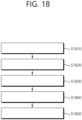
- FIG. 18 shows a method for a first device to perform wireless communication, based on an embodiment of the present disclosure.
- the embodiment of FIG. 18 may be combined with various embodiments of the present disclosure.
- the first device may receive, from a base station, information related to a physical uplink control channel (PUCCH) resource and information related to M sidelink (SL) slots.
- the first device may perform N physical sidelink shared channel (PSSCH) transmissions, based on N SL slots among the M SL slots.
- the first device may determine one physical sidelink feedback channel (PSFCH) slot related to the N PSSCH transmissions.
- the first device may receive information on K SL hybrid automatic repeat request (HARQ) feedbacks on the one PSFCH slot, in response to the N PSSCH transmissions.
- PUCCH physical uplink control channel
- SL sidelink
- HARQ hybrid automatic repeat request
- the first device may transmit, to the base station, information on L HARQ feedbacks based on the PUCCH resource.
- the one PSFCH slot may be related to L SL slots, and the M, the N, the K and the L may be positive integers, and the L may be greater than or equal to the M, and the M may be greater than or equal to the N, and the N may be greater than or equal to the K.
- the L which is a number of SL slots related to the one PSFCH slot may be equal to a period of a PSFCH resource.
- information on L - N HARQ feedbacks related to L - N SL slots in which the N PSSCH transmissions are not performed among the L SL slots related to the one PSFCH slot may be generated as ACK, and the L may be greater than the N.
- the information on the L HARQ feedbacks may be transmitted to the base station based on the PUCCH resource, and based on the N being less than the threshold, the information on the L HARQ feedbacks may not be transmitted to the base station based on the PUCCH resource.
- L - N NACKs may be received based on L - N PSFCH resources related to L - N SL slots in which the N PSSCH transmissions are not performed among the L SL slots related to the one PSFCH slot, and the L - N PSFCH resources may be included in the one PSFCH slot, and the K may be equal to the M, and the L may be greater than the N.
- information on L - N HARQ feedbacks related to the L - N NACKs received based on the L - N PSFCH resources may be generated as ACK.
- SL HARQ feedback may not be received based on N - K PSFCH resources on the one PSFCH slot, in response to the N PSSCH transmissions, and information on N - K HARQ feedbacks related to the N - K PSFCH resources may be generated as NACK, and the K may be less than the N.
- SL HARQ feedback may not be received based on N - K PSFCH resources on the one PSFCH slot, in response to the N PSSCH transmissions, and information on N - K HARQ feedbacks related to the N - K PSFCH resources may be generated as ACK, and the K may be less than the N.
- the PUCCH resource and the M SL slots may be allocated to the first device by a configured grant (CG).
- CG configured grant
- the information on the L HARQ feedbacks may not be transmitted to the base station based on the PUCCH resource.
- the PUCCH resource and the M SL slots may be allocated to the first device by a dynamic grant (DG).
- DG dynamic grant
- the information on the L HARQ feedbacks may be transmitted to the base station based on the PUCCH resource, and based on the L being greater than the N, information on L - N HARQ feedbacks related to L - N SL slots in which the N PSSCH transmissions are not performed among the L SL slots may be generated as ACK.
- the SL slot may be a slot including a specific number or more of UL symbols.
- the processor 102 of the first device 100 may control the transceiver 106 to receive, from a base station, information related to a physical uplink control channel (PUCCH) resource and information related to M sidelink (SL) slots.
- the processor 102 of the first device 100 may control the transceiver 106 to perform N physical sidelink shared channel (PSSCH) transmissions, based on N SL slots among the M SL slots.
- the processor 102 of the first device 100 may determine one physical sidelink feedback channel (PSFCH) slot related to the N PSSCH transmissions.
- PUCCH physical uplink control channel
- SL sidelink
- the processor 102 of the first device 100 may control the transceiver 106 to receive information on K SL hybrid automatic repeat request (HARQ) feedbacks on the one PSFCH slot, in response to the N PSSCH transmissions.
- the processor 102 of the first device 100 may control the transceiver 106 to transmit, to the base station, information on L HARQ feedbacks based on the PUCCH resource.
- the one PSFCH slot may be related to L SL slots, and the M, the N, the K and the L may be positive integers, and the L may be greater than or equal to the M, and the M may be greater than or equal to the N, and the N may be greater than or equal to the K.
- a first device configured to perform wireless communication may be provided.
- the first device may comprise: one or more memories storing instructions; one or more transceivers; and one or more processors connected to the one or more memories and the one or more transceivers.
- the one or more processors may execute the instructions to: receive, from a base station, information related to a physical uplink control channel (PUCCH) resource and information related to M sidelink (SL) slots; perform N physical sidelink shared channel (PSSCH) transmissions, based on N SL slots among the M SL slots; determine one physical sidelink feedback channel (PSFCH) slot related to the N PSSCH transmissions; receive information on K SL hybrid automatic repeat request (HARQ) feedbacks on the one PSFCH slot, in response to the N PSSCH transmissions; and transmit, to the base station, information on L HARQ feedbacks based on the PUCCH resource.
- PUCCH physical uplink control channel
- PSSCH physical sidelink shared channel
- PSFCH physical sidelink feedback channel
- HARQ hybrid automatic repeat request
- the one PSFCH slot may be related to L SL slots, and the M, the N, the K and the L may be positive integers, and the L may be greater than or equal to the M, and the M may be greater than or equal to the N, and the N may be greater than or equal to the K.
- an apparatus configured to control a first user equipment (UE) performing wireless communication
- the apparatus may comprise: one or more processors; and one or more memories operably connected to the one or more processors and storing instructions.
- the one or more processors may execute the instructions to: receive, from a base station, information related to a physical uplink control channel (PUCCH) resource and information related to M sidelink (SL) slots; perform N physical sidelink shared channel (PSSCH) transmissions, based on N SL slots among the M SL slots; determine one physical sidelink feedback channel (PSFCH) slot related to the N PSSCH transmissions; receive information on K SL hybrid automatic repeat request (HARQ) feedbacks on the one PSFCH slot, in response to the N PSSCH transmissions; and transmit, to the base station, information on L HARQ feedbacks based on the PUCCH resource.
- PUCCH physical uplink control channel
- PSSCH physical sidelink shared channel
- PSFCH physical sidelink feedback channel
- HARQ hybrid automatic repeat request
- the one PSFCH slot may be related to L SL slots, and the M, the N, the K and the L may be positive integers, and the L may be greater than or equal to the M, and the M may be greater than or equal to the N, and the N may be greater than or equal to the K.
- a non-transitory computer-readable storage medium storing instructions may be provided.
- the instructions when executed, may cause a first device to: receive, from a base station, information related to a physical uplink control channel (PUCCH) resource and information related to M sidelink (SL) slots; perform N physical sidelink shared channel (PSSCH) transmissions, based on N SL slots among the M SL slots; determine one physical sidelink feedback channel (PSFCH) slot related to the N PSSCH transmissions; receive information on K SL hybrid automatic repeat request
- PUCCH physical uplink control channel
- PSSCH physical sidelink shared channel
- PSFCH physical sidelink feedback channel
- the one PSFCH slot may be related to L SL slots, and the M, the N, the K and the L may be positive integers, and the L may be greater than or equal to the M, and the M may be greater than or equal to the N, and the N may be greater than or equal to the K.
- FIG. 19 shows a method for a base station to perform wireless communication, based on an embodiment of the present disclosure.
- the embodiment of FIG. 19 may be combined with various embodiments of the present disclosure.
- N physical sidelink shared channel (PSSCH) transmissions may be performed by the first device based on N SL slots among the M SL slots, and one physical sidelink feedback channel (PSFCH) slot related to the N PSSCH transmissions may be determined by the first device, and information on K SL HARQ feedbacks may be received by the first device on the one PSFCH slot in response to the N PSSCH transmissions.
- the one PSFCH slot may be related to L SL slots, and the M, the N, the K and the L may be positive integers, and the L may be greater than or equal to the M, and the M may be greater than or equal to the N, and the N may be greater than or equal to the K.
- the processor 202 of the base station 200 may control the transceiver 206 to transmit, to a first device, information related to a physical uplink control channel (PUCCH) resource and information related to M sidelink (SL) slots.
- the processor 202 of the base station 200 may control the transceiver 206 to receive, from the first device, information on L hybrid automatic repeat request (HARQ) feedbacks based on the PUCCH resource.
- HARQ L hybrid automatic repeat request
- N physical sidelink shared channel (PSSCH) transmissions may be performed by the first device based on N SL slots among the M SL slots, and one physical sidelink feedback channel (PSFCH) slot related to the N PSSCH transmissions may be determined by the first device, and information on K SL HARQ feedbacks may be received by the first device on the one PSFCH slot in response to the N PSSCH transmissions.
- the one PSFCH slot may be related to L SL slots, and the M, the N, the K and the L may be positive integers, and the L may be greater than or equal to the M, and the M may be greater than or equal to the N, and the N may be greater than or equal to the K.
- a base station configured to perform wireless communication may be provided.
- the base station may comprise: one or more memories storing instructions; one or more transceivers; and one or more processors connected to the one or more memories and the one or more transceivers.
- the one or more processors may execute the instructions to: transmit, to a first device, information related to a physical uplink control channel (PUCCH) resource and information related to M sidelink (SL) slots; and receive, from the first device, information on L hybrid automatic repeat request (HARQ) feedbacks based on the PUCCH resource.
- PUCCH physical uplink control channel
- SL sidelink
- HARQ L hybrid automatic repeat request
- N physical sidelink shared channel (PSSCH) transmissions may be performed by the first device based on N SL slots among the M SL slots, and one physical sidelink feedback channel (PSFCH) slot related to the N PSSCH transmissions may be determined by the first device, and information on K SL HARQ feedbacks may be received by the first device on the one PSFCH slot in response to the N PSSCH transmissions.
- the one PSFCH slot may be related to L SL slots, and the M, the N, the K and the L may be positive integers, and the L may be greater than or equal to the M, and the M may be greater than or equal to the N, and the N may be greater than or equal to the K.
- an apparatus configured to control a base station performing wireless communication may comprise: one or more processors; and one or more memories operably connected to the one or more processors and storing instructions.
- the one or more processors may execute the instructions to: transmit, to a first user equipment (UE), information related to a physical uplink control channel (PUCCH) resource and information related to M sidelink (SL) slots; and receive, from the first UE, information on L hybrid automatic repeat request (HARQ) feedbacks based on the PUCCH resource.
- UE user equipment
- PUCCH physical uplink control channel
- SL sidelink
- N physical sidelink shared channel (PSSCH) transmissions may be performed by the first UE based on N SL slots among the M SL slots, and one physical sidelink feedback channel (PSFCH) slot related to the N PSSCH transmissions may be determined by the first UE, and information on K SL HARQ feedbacks may be received by the first UE on the one PSFCH slot in response to the N PSSCH transmissions.
- the one PSFCH slot may be related to L SL slots, and the M, the N, the K and the L may be positive integers, and the L may be greater than or equal to the M, and the M may be greater than or equal to the N, and the N may be greater than or equal to the K.
- a non-transitory computer-readable storage medium storing instructions may be provided.
- the instructions when executed, may cause a base station to: transmit, to a first device, information related to a physical uplink control channel (PUCCH) resource and information related to M sidelink (SL) slots; and receive, from the first device, information on L hybrid automatic repeat request (HARQ) feedbacks based on the PUCCH resource.
- PUCCH physical uplink control channel
- SL sidelink
- HARQ L hybrid automatic repeat request
- N physical sidelink shared channel (PSSCH) transmissions may be performed by the first device based on N SL slots among the M SL slots, and one physical sidelink feedback channel (PSFCH) slot related to the N PSSCH transmissions may be determined by the first device, and information on K SL HARQ feedbacks may be received by the first device on the one PSFCH slot in response to the N PSSCH transmissions.
- the one PSFCH slot may be related to L SL slots, and the M, the N, the K and the L may be positive integers, and the L may be greater than or equal to the M, and the M may be greater than or equal to the N, and the N may be greater than or equal to the K.
- FIG. 20 shows a method for a first device to perform wireless communication, based on an embodiment of the present disclosure.
- the embodiment of FIG. 20 may be combined with various embodiments of the present disclosure.
- the first device may receive, from a base station, information related to a sidelink (SL) bandwidth part (BWP).
- the first device may receive, from the base station, information related to an uplink (UL) BWP.
- the first device may receive, from the base station, information related to a SL resource and information related to a UL resource for reporting hybrid automatic repeat request (HARQ) feedback.
- the first device may transmit, to a second device through a physical sidelink shared channel (PSSCH), data for which the HARQ feedback is disabled based on the SL resource in the SL BWP.
- PSSCH physical sidelink shared channel
- the first device may generate ACK related to transmission of the data for which the HARQ feedback is disabled.
- the first device may transmit, to the base station, the ACK based on the UL resource in the UL BWP.
- the ACK related to the transmission of the data may be generated by the first device.
- the ACK related to the transmission of the data may be generated by the first device, based on retransmission of the data not being required.
- the UL resource for reporting the HARQ feedback may be a resource related to the SL resource.
- a retransmission resource for the data may not be allocated to the first device by the base station based on the ACK.
- the first device may determine a physical sidelink feedback channel (PSFCH) resource based on a slot index of a resource related to the PSSCH and a subchannel index of the resource related to the PSSCH.
- the information related to the UL resource may include information related to a slot offset between the UL resource and the PSFCH resource, and the UL resource may be included in a slot after the slot offset from a slot including the PSFCH resource.
- the HARQ feedback for the data may not be transmitted on the PSFCH resource by the second device, in response to the transmission of the data for which the HARQ feedback is disabled.
- the first device may transmit, to the second device through the PSSCH, a sidelink control information (SCI) including HARQ feedback disabled information representing disabling of the HARQ feedback for the data.
- SCI sidelink control information
- the SL resource may be a periodic resource or a dynamic resource allocated for the first device by the base station, and the information related to the SL resource and the information related to the UL resource may be received from the base station through at least one of a downlink control information (DCI) or a radio resource control (RRC) message.
- DCI downlink control information
- RRC radio resource control
- the ACK may be transmitted to the base station based on the UL resource.
- the processor 102 of the first device 100 may control the transceiver 106 to receive, from a base station, information related to a sidelink (SL) bandwidth part (BWP).
- the processor 102 of the first device 100 may control the transceiver 106 to receive, from the base station, information related to an uplink (UL) BWP.
- the processor 102 of the first device 100 may control the transceiver 106 to receive, from the base station, information related to a SL resource and information related to a UL resource for reporting hybrid automatic repeat request (HARQ) feedback.
- HARQ hybrid automatic repeat request
- the processor 102 of the first device 100 may control the transceiver 106 to transmit, to a second device through a physical sidelink shared channel (PSSCH), data for which the HARQ feedback is disabled based on the SL resource in the SL BWP.
- the processor 102 of the first device 100 may generate ACK related to transmission of the data for which the HARQ feedback is disabled.
- the processor 102 of the first device 100 may control the transceiver 106 to transmit, to the base station, the ACK based on the UL resource in the UL BWP.
- PSSCH physical sidelink shared channel
- a first device configured to perform wireless communication may be provided.
- the first device may comprise: one or more memories storing instructions; one or more transceivers; and one or more processors connected to the one or more memories and the one or more transceivers.
- the one or more processors may execute the instructions to: receive, from a base station, information related to a sidelink (SL) bandwidth part (BWP); receive, from the base station, information related to an uplink (UL) BWP; receive, from the base station, information related to a SL resource and information related to a UL resource for reporting hybrid automatic repeat request (HARQ) feedback; transmit, to a second UE through a physical sidelink shared channel (PSSCH), data for which the HARQ feedback is disabled based on the SL resource in the SL BWP; generate ACK related to transmission of the data for which the HARQ feedback is disabled; and transmit, to the base station, the ACK based on the UL resource in the UL BWP.
- PSSCH physical sidelink shared channel
- an apparatus configured to control a first user equipment (UE) performing wireless communication
- the apparatus may comprise: one or more processors; and one or more memories operably connected to the one or more processors and storing instructions.
- the one or more processors may execute the instructions to: receive, from a base station, information related to a sidelink (SL) bandwidth part (BWP); receive, from the base station, information related to an uplink (UL) BWP; receive, from the base station, information related to a SL resource and information related to a UL resource for reporting hybrid automatic repeat request (HARQ) feedback; transmit, to a second device through a physical sidelink shared channel (PSSCH), data for which the HARQ feedback is disabled based on the SL resource in the SL BWP; generate ACK related to transmission of the data for which the HARQ feedback is disabled; and transmit, to the base station, the ACK based on the UL resource in the UL BWP.
- PSSCH physical sidelink shared channel
- a non-transitory computer-readable storage medium storing instructions may be provided.
- the instructions when executed, may cause a first device to: receive, from a base station, information related to a sidelink (SL) bandwidth part (BWP); receive, from the base station, information related to an uplink (UL) BWP; receive, from the base station, information related to a SL resource and information related to a UL resource for reporting hybrid automatic repeat request (HARQ) feedback; transmit, to a second device through a physical sidelink shared channel (PSSCH), data for which the HARQ feedback is disabled based on the SL resource in the SL BWP; generate ACK related to transmission of the data for which the HARQ feedback is disabled; and transmit, to the base station, the ACK based on the UL resource in the UL BWP.
- PSSCH physical sidelink shared channel
- FIG. 21 shows a method for a base station to perform wireless communication, based on an embodiment of the present disclosure.
- the embodiment of FIG. 21 may be combined with various embodiments of the present disclosure.
- the base station may transmit, to a first device, information related to a sidelink (SL) bandwidth part (BWP).
- the base station may transmit, to the first device, information related to an uplink (UL) BWP.
- the base station may transmit, to the first device, information related to a SL resource and information related to a UL resource for reporting hybrid automatic repeat request (HARQ) feedback.
- HARQ hybrid automatic repeat request
- the base station may receive ACK related to transmission of the data from the first device based on the UL resource in the UL BWP, based on the first device transmitting data for which the HARQ feedback is disabled based on the SL resource in the SL BWP to a second device through a physical sidelink shared channel (PSSCH).
- PSSCH physical sidelink shared channel
- the processor 202 of the base station 200 may control the transceiver 206 to transmit, to a first device, information related to a sidelink (SL) bandwidth part (BWP).
- the processor 202 of the base station 200 may control the transceiver 206 to transmit, to the first device, information related to an uplink (UL) BWP.
- the processor 202 of the base station 200 may control the transceiver 206 to transmit, to the first device, information related to a SL resource and information related to a UL resource for reporting hybrid automatic repeat request (HARQ) feedback.
- HARQ hybrid automatic repeat request
- the processor 202 of the base station 200 may control the transceiver 206 to receive ACK related to transmission of the data from the first device based on the UL resource in the UL BWP, based on the first device transmitting data for which the HARQ feedback is disabled based on the SL resource in the SL BWP to a second device through a physical sidelink shared channel (PSSCH).
- PSSCH physical sidelink shared channel
- a base station configured to perform wireless communication may be provided.
- the base station may comprise: one or more memories storing instructions; one or more transceivers; and one or more processors connected to the one or more memories and the one or more transceivers.
- the one or more processors may execute the instructions to: transmit, to a first device, information related to a sidelink (SL) bandwidth part (BWP); transmit, to the first device, information related to an uplink (UL) BWP; transmit, to the first device, information related to a SL resource and information related to a UL resource for reporting hybrid automatic repeat request (HARQ) feedback; and based on the first device transmitting data for which the HARQ feedback is disabled based on the SL resource in the SL BWP to a second device through a physical sidelink shared channel (PSSCH), receive ACK related to transmission of the data from the first device based on the UL resource in the UL BWP.
- PSSCH physical sidelink shared channel
- an apparatus configured to control a base station performing wireless communication may comprise: one or more processors; and one or more memories operably connected to the one or more processors and storing instructions.
- the one or more processors may execute the instructions to: transmit, to a first user equipment (UE), information related to a sidelink (SL) bandwidth part (BWP); transmit, to the first UE, information related to an uplink (UL) BWP; transmit, to the first UE, information related to a SL resource and information related to a UL resource for reporting hybrid automatic repeat request (HARQ) feedback; and based on the first UE transmitting data for which the HARQ feedback is disabled based on the SL resource in the SL BWP to a second UE through a physical sidelink shared channel (PSSCH), receive ACK related to transmission of the data from the first UE based on the UL resource in the UL BWP.
- UE user equipment
- UL uplink
- HARQ hybrid automatic repeat request
- a non-transitory computer-readable storage medium storing instructions may be provided.
- the instructions when executed, may cause a base station to: transmit, to a first device, information related to a sidelink (SL) bandwidth part (BWP); transmit, to the first device, information related to an uplink (UL) BWP; transmit, to the first device, information related to a SL resource and information related to a UL resource for reporting hybrid automatic repeat request (HARQ) feedback; and based on the first device transmitting data for which the HARQ feedback is disabled based on the SL resource in the SL BWP to a second device through a physical sidelink shared channel (PSSCH), receive ACK related to transmission of the data from the first device based on the UL resource in the UL BWP.
- PSSCH physical sidelink shared channel
- FIG. 22 shows a communication system 1, based on an embodiment of the present disclosure.
- a communication system 1 to which various embodiments of the present disclosure are applied includes wireless devices, Base Stations (BSs), and a network.
- the wireless devices represent devices performing communication using Radio Access Technology (RAT) (e.g., 5G New RAT (NR)) or Long-Term Evolution (LTE)) and may be referred to as communication/radio/SG devices.
- RAT Radio Access Technology
- the wireless devices may include, without being limited to, a robot 100a, vehicles 100b-1 and 100b-2, an eXtended Reality (XR) device 100c, a hand-held device 100d, a home appliance 100e, an Internet of Things (IoT) device 100f, and an Artificial Intelligence (AI) device/server 400.
- RAT Radio Access Technology
- NR 5G New RAT
- LTE Long-Term Evolution
- the wireless devices may include, without being limited to, a robot 100a, vehicles 100b-1 and 100b-2, an eXtended Reality (XR) device 100c, a hand-held device 100d
- the vehicles may include a vehicle having a wireless communication function, an autonomous vehicle, and a vehicle capable of performing communication between vehicles.
- the vehicles may include an Unmanned Aerial Vehicle (UAV) (e.g., a drone).
- UAV Unmanned Aerial Vehicle
- the XR device may include an Augmented Reality (AR)/Virtual Reality (VR)/Mixed Reality (MR) device and may be implemented in the form of a Head-Mounted Device (HMD), a Head-Up Display (HUD) mounted in a vehicle, a television, a smartphone, a computer, a wearable device, a home appliance device, a digital signage, a vehicle, a robot, etc.
- the hand-held device may include a smartphone, a smartpad, a wearable device (e.g., a smartwatch or a smartglasses), and a computer (e.g., a notebook).
- the home appliance may include a TV, a refrigerator, and a washing machine.
- the IoT device may include a sensor and a smartmeter.
- the BSs and the network may be implemented as wireless devices and a specific wireless device 200a may operate as a BS/network node with respect to other wireless devices.
- wireless communication technology implemented in wireless devices 100a to 100f of the present disclosure may include Narrowband Internet of Things for low-power communication in addition to LTE, NR, and 6G.
- NB-IoT technology may be an example of Low Power Wide Area Network (LPWAN) technology and may be implemented as standards such as LTE Cat NB1, and/or LTE Cat NB2, and is not limited to the name described above.
- the wireless communication technology implemented in the wireless devices 100a to 100f of the present disclosure may perform communication based on LTE-M technology.
- the LTE-M technology may be an example of the LPWAN and may be called by various names including enhanced Machine Type Communication (eMTC), and the like.
- eMTC enhanced Machine Type Communication
- the LTE-M technology may be implemented as at least any one of various standards such as 1) LTE CAT 0, 2) LTE Cat M1, 3) LTE Cat M2, 4) LTE non-Bandwidth Limited (non-BL), 5) LTE-MTC, 6) LTE Machine Type Communication, and/or 7) LTE M, and is not limited to the name described above.
- the wireless communication technology implemented in the wireless devices 100a to 100f of the present disclosure may include at least one of Bluetooth, Low Power Wide Area Network (LPWAN), and ZigBee considering the low-power communication, and is not limited to the name described above.
- the ZigBee technology may generate personal area networks (PAN) related to small/low-power digital communication based on various standards including IEEE 802.15.4, and the like, and may be called by various names.
- PAN personal area networks
- the wireless devices 100a to 100f may be connected to the network 300 via the BSs 200.
- An AI technology may be applied to the wireless devices 100a to 100f and the wireless devices 100a to 100f may be connected to the AI server 400 via the network 300.
- the network 300 may be configured using a 3G network, a 4G (e.g., LTE) network, or a 5G (e.g., NR) network.
- the wireless devices 100a to 100f may communicate with each other through the BSs 200/network 300, the wireless devices 100a to 100f may perform direct communication (e.g., sidelink communication) with each other without passing through the BSs/network.
- the vehicles 100b-1 and 100b-2 may perform direct communication (e.g.
- V2V Vehicle-to-Vehicle
- V2X Vehicle-to-everything
- Wireless communication/connections 150a, 150b, or 150c may be established between the wireless devices 100a to 100fBS 200, or BS 200BS 200.
- the wireless communication/connections may be established through various RATs (e.g., 5G NR) such as uplink/downlink communication 150a, sidelink communication 150b (or, D2D communication), or inter BS communication (e.g., relay, Integrated Access Backhaul (IAB)).
- the wireless devices and the BSs/the wireless devices may transmit/receive radio signals to/from each other through the wireless communication/connections 150a and 150b.
- the wireless communication/connections 150a and 150b may transmit/receive signals through various physical channels.
- various configuration information configuring processes various signal processing processes (e.g., channel encoding/decoding, modulation/demodulation, and resource mapping/demapping), and resource allocating processes, for transmitting/receiving radio signals, may be performed based on the various proposals of the present disclosure.
- various signal processing processes e.g., channel encoding/decoding, modulation/demodulation, and resource mapping/demapping
- resource allocating processes for transmitting/receiving radio signals
- FIG. 23 shows wireless devices, based on an embodiment of the present disclosure.
- a first wireless device 100 and a second wireless device 200 may transmit radio signals through a variety of RATs (e.g., LTE and NR).
- ⁇ the first wireless device 100 and the second wireless device 200 ⁇ may correspond to ⁇ the wireless device 100x and the BS 200 ⁇ and/or ⁇ the wireless device 100x and the wireless device 100x ⁇ of FIG. 22 .
- the first wireless device 100 may include one or more processors 102 and one or more memories 104 and additionally further include one or more transceivers 106 and/or one or more antennas 108.
- the processor(s) 102 may control the memory(s) 104 and/or the transceiver(s) 106 and may be configured to implement the descriptions, functions, procedures, proposals, methods, and/or operational flowcharts disclosed in this document.
- the processor(s) 102 may process information within the memory(s) 104 to generate first information/signals and then transmit radio signals including the first information/signals through the transceiver(s) 106.
- the processor(s) 102 may receive radio signals including second information/signals through the transceiver 106 and then store information obtained by processing the second information/signals in the memory(s) 104.
- the memory(s) 104 may be connected to the processor(s) 102 and may store a variety of information related to operations of the processor(s) 102.
- the memory(s) 104 may store software code including commands for performing a part or the entirety of processes controlled by the processor(s) 102 or for performing the descriptions, functions, procedures, proposals, methods, and/or operational flowcharts disclosed in this document.
- the processor(s) 102 and the memory(s) 104 may be a part of a communication modem/circuit/chip designed to implement RAT (e.g., LTE or NR).
- the transceiver(s) 106 may be connected to the processor(s) 102 and transmit and/or receive radio signals through one or more antennas 108.
- Each of the transceiver(s) 106 may include a transmitter and/or a receiver.
- the transceiver(s) 106 may be interchangeably used with Radio Frequency (RF) unit(s).
- the wireless device may represent a communication modem/circuit/chip.
- the second wireless device 200 may include one or more processors 202 and one or more memories 204 and additionally further include one or more transceivers 206 and/or one or more antennas 208.
- the processor(s) 202 may control the memory(s) 204 and/or the transceiver(s) 206 and may be configured to implement the descriptions, functions, procedures, proposals, methods, and/or operational flowcharts disclosed in this document.
- the processor(s) 202 may process information within the memory(s) 204 to generate third information/signals and then transmit radio signals including the third information/signals through the transceiver(s) 206.
- the processor(s) 202 may receive radio signals including fourth information/signals through the transceiver(s) 106 and then store information obtained by processing the fourth information/signals in the memory(s) 204.
- the memory(s) 204 may be connected to the processor(s) 202 and may store a variety of information related to operations of the processor(s) 202.
- the memory(s) 204 may store software code including commands for performing a part or the entirety of processes controlled by the processor(s) 202 or for performing the descriptions, functions, procedures, proposals, methods, and/or operational flowcharts disclosed in this document.
- the processor(s) 202 and the memory(s) 204 may be a part of a communication modem/circuit/chip designed to implement RAT (e.g., LTE or NR).
- the transceiver(s) 206 may be connected to the processor(s) 202 and transmit and/or receive radio signals through one or more antennas 208.
- Each of the transceiver(s) 206 may include a transmitter and/or a receiver.
- the transceiver(s) 206 may be interchangeably used with RF unit(s).
- the wireless device may represent a communication modem/circuit/chip.
- One or more protocol layers may be implemented by, without being limited to, one or more processors 102 and 202.
- the one or more processors 102 and 202 may implement one or more layers (e.g., functional layers such as PHY, MAC, RLC, PDCP, RRC, and SDAP).
- the one or more processors 102 and 202 may generate one or more Protocol Data Units (PDUs) and/or one or more Service Data Unit (SDUs) according to the descriptions, functions, procedures, proposals, methods, and/or operational flowcharts disclosed in this document.
- PDUs Protocol Data Units
- SDUs Service Data Unit
- the one or more processors 102 and 202 may generate messages, control information, data, or information according to the descriptions, functions, procedures, proposals, methods, and/or operational flowcharts disclosed in this document.
- the one or more processors 102 and 202 may generate signals (e.g., baseband signals) including PDUs, SDUs, messages, control information, data, or information according to the descriptions, functions, procedures, proposals, methods, and/or operational flowcharts disclosed in this document and provide the generated signals to the one or more transceivers 106 and 206.
- the one or more processors 102 and 202 may receive the signals (e.g., baseband signals) from the one or more transceivers 106 and 206 and acquire the PDUs, SDUs, messages, control information, data, or information according to the descriptions, functions, procedures, proposals, methods, and/or operational flowcharts disclosed in this document.
- signals e.g., baseband signals
- the one or more processors 102 and 202 may be referred to as controllers, microcontrollers, microprocessors, or microcomputers.
- the one or more processors 102 and 202 may be implemented by hardware, firmware, software, or a combination thereof.
- ASICs Application Specific Integrated Circuits
- DSPs Digital Signal Processors
- DSPDs Digital Signal Processing Devices
- PLDs Programmable Logic Devices
- FPGAs Field Programmable Gate Arrays
- the descriptions, functions, procedures, proposals, methods, and/or operational flowcharts disclosed in this document may be implemented using firmware or software and the firmware or software may be configured to include the modules, procedures, or functions.
- Firmware or software configured to perform the descriptions, functions, procedures, proposals, methods, and/or operational flowcharts disclosed in this document may be included in the one or more processors 102 and 202 or stored in the one or more memories 104 and 204 so as to be driven by the one or more processors 102 and 202.
- the descriptions, functions, procedures, proposals, methods, and/or operational flowcharts disclosed in this document may be implemented using firmware or software in the form of code, commands, and/or a set of commands.
- the one or more memories 104 and 204 may be connected to the one or more processors 102 and 202 and store various types of data, signals, messages, information, programs, code, instructions, and/or commands.
- the one or more memories 104 and 204 may be configured by Read-Only Memories (ROMs), Random Access Memories (RAMs), Electrically Erasable Programmable Read-Only Memories (EPROMs), flash memories, hard drives, registers, cash memories, computer-readable storage media, and/or combinations thereof.
- the one or more memories 104 and 204 may be located at the interior and/or exterior of the one or more processors 102 and 202.
- the one or more memories 104 and 204 may be connected to the one or more processors 102 and 202 through various technologies such as wired or wireless connection.
- the one or more transceivers 106 and 206 may transmit user data, control information, and/or radio signals/channels, mentioned in the methods and/or operational flowcharts of this document, to one or more other devices.
- the one or more transceivers 106 and 206 may receive user data, control information, and/or radio signals/channels, mentioned in the descriptions, functions, procedures, proposals, methods, and/or operational flowcharts disclosed in this document, from one or more other devices.
- the one or more transceivers 106 and 206 may be connected to the one or more processors 102 and 202 and transmit and receive radio signals.
- the one or more processors 102 and 202 may perform control so that the one or more transceivers 106 and 206 may transmit user data, control information, or radio signals to one or more other devices.
- the one or more processors 102 and 202 may perform control so that the one or more transceivers 106 and 206 may receive user data, control information, or radio signals from one or more other devices.
- the one or more transceivers 106 and 206 may convert the user data, control information, radio signals/channels, etc. processed using the one or more processors 102 and 202 from the base band signals into the RF band signals.
- the one or more transceivers 106 and 206 may include (analog) oscillators and/or filters.
- FIG. 24 shows a signal process circuit for a transmission signal, based on an embodiment of the present disclosure.
- a signal processing circuit 1000 may include scramblers 1010, modulators 1020, a layer mapper 1030, a precoder 1040, resource mappers 1050, and signal generators 1060.
- An operation/function of FIG. 24 may be performed, without being limited to, the processors 102 and 202 and/or the transceivers 106 and 206 of FIG. 23 .
- Hardware elements of FIG. 24 may be implemented by the processors 102 and 202 and/or the transceivers 106 and 206 of FIG. 23 .
- blocks 1010 to 1060 may be implemented by the processors 102 and 202 of FIG. 23 .
- the blocks 1010 to 1050 may be implemented by the processors 102 and 202 of FIG. 23 and the block 1060 may be implemented by the transceivers 106 and 206 of FIG. 23 .
- Codewords may be converted into radio signals via the signal processing circuit 1000 of FIG. 24 .
- the codewords are encoded bit sequences of information blocks.
- the information blocks may include transport blocks (e.g., a UL-SCH transport block, a DL-SCH transport block).
- the radio signals may be transmitted through various physical channels (e.g., a PUSCH and a PDSCH).
- the codewords may be converted into scrambled bit sequences by the scramblers 1010.
- Scramble sequences used for scrambling may be generated based on an initialization value, and the initialization value may include ID information of a wireless device.
- the scrambled bit sequences may be modulated to modulation symbol sequences by the modulators 1020.
- a modulation scheme may include pi/2-Binary Phase Shift Keying (pi/2-BPSK), m-Phase Shift Keying (m-PSK), and m-Quadrature Amplitude Modulation (m-QAM).
- Complex modulation symbol sequences may be mapped to one or more transport layers by the layer mapper 1030.
- Modulation symbols of each transport layer may be mapped (precoded) to corresponding antenna port(s) by the precoder 1040.
- Outputs z of the precoder 1040 may be obtained by multiplying outputs y of the layer mapper 1030 by an N*M precoding matrix W.
- N is the number of antenna ports and M is the number of transport layers.
- the precoder 1040 may perform precoding after performing transform precoding (e.g., DFT) for complex modulation symbols. Alternatively, the precoder 1040 may perform precoding without performing transform precoding.
- transform precoding e.g., DFT
- the resource mappers 1050 may map modulation symbols of each antenna port to time-frequency resources.
- the time-frequency resources may include a plurality of symbols (e.g., a CP-OFDMA symbols and DFT-s-OFDMA symbols) in the time domain and a plurality of subcarriers in the frequency domain.
- the signal generators 1060 may generate radio signals from the mapped modulation symbols and the generated radio signals may be transmitted to other devices through each antenna.
- the signal generators 1060 may include Inverse Fast Fourier Transform (IFFT) modules, Cyclic Prefix (CP) inserters, Digital-to-Analog Converters (DACs), and frequency up-converters.
- IFFT Inverse Fast Fourier Transform
- CP Cyclic Prefix
- DACs Digital-to-Analog Converters
- Signal processing procedures for a signal received in the wireless device may be configured in a reverse manner of the signal processing procedures 1010 to 1060 of FIG. 24 .
- the wireless devices e.g., 100 and 200 of FIG. 23
- the received radio signals may be converted into baseband signals through signal restorers.
- the signal restorers may include frequency downlink converters, Analog-to-Digital Converters (ADCs), CP remover, and Fast Fourier Transform (FFT) modules.
- ADCs Analog-to-Digital Converters
- FFT Fast Fourier Transform
- the baseband signals may be restored to codewords through a resource demapping procedure, a postcoding procedure, a demodulation processor, and a descrambling procedure.
- a signal processing circuit for a reception signal may include signal restorers, resource demappers, a postcoder, demodulators, descramblers, and decoders.
- FIG. 25 shows another example of a wireless device, based on an embodiment of the present disclosure.
- the wireless device may be implemented in various forms according to a use-case/service (refer to FIG. 22 ).
- wireless devices 100 and 200 may correspond to the wireless devices 100 and 200 of FIG. 23 and may be configured by various elements, components, units/portions, and/or modules.
- each of the wireless devices 100 and 200 may include a communication unit 110, a control unit 120, a memory unit 130, and additional components 140.
- the communication unit may include a communication circuit 112 and transceiver(s) 114.
- the communication circuit 112 may include the one or more processors 102 and 202 and/or the one or more memories 104 and 204 of FIG. 23 .
- the transceiver(s) 114 may include the one or more transceivers 106 and 206 and/or the one or more antennas 108 and 208 of FIG. 23 .
- the control unit 120 is electrically connected to the communication unit 110, the memory 130, and the additional components 140 and controls overall operation of the wireless devices. For example, the control unit 120 may control an electric/mechanical operation of the wireless device based on programs/code/commands/information stored in the memory unit 130.
- the control unit 120 may transmit the information stored in the memory unit 130 to the exterior (e.g., other communication devices) via the communication unit 110 through a wireless/wired interface or store, in the memory unit 130, information received through the wireless/wired interface from the exterior (e.g., other communication devices) via the communication unit 110.
- the additional components 140 may be variously configured according to types of wireless devices.
- the additional components 140 may include at least one of a power unit/battery, input/output (I/O) unit, a driving unit, and a computing unit.
- the wireless device may be implemented in the form of, without being limited to, the robot (100a of FIG. 22 ), the vehicles (100b-1 and 100b-2 of FIG. 22 ), the XR device (100c of FIG. 22 ), the hand-held device (100d of FIG. 22 ), the home appliance (100e of FIG. 22 ), the IoT device (100f of FIG.
- the wireless device may be used in a mobile or fixed place according to a use-example/service.
- the entirety of the various elements, components, units/portions, and/or modules in the wireless devices 100 and 200 may be connected to each other through a wired interface or at least a part thereof may be wirelessly connected through the communication unit 110.
- the control unit 120 and the communication unit 110 may be connected by wire and the control unit 120 and first units (e.g., 130 and 140) may be wirelessly connected through the communication unit 110.
- Each element, component, unit/portion, and/or module within the wireless devices 100 and 200 may further include one or more elements.
- the control unit 120 may be configured by a set of one or more processors.
- control unit 120 may be configured by a set of a communication control processor, an application processor, an Electronic Control Unit (ECU), a graphical processing unit, and a memory control processor.
- memory 130 may be configured by a Random Access Memory (RAM), a Dynamic RAM (DRAM), a Read Only Memory (ROM)), a flash memory, a volatile memory, a non-volatile memory, and/or a combination thereof.
- RAM Random Access Memory
- DRAM Dynamic RAM
- ROM Read Only Memory
- flash memory a volatile memory
- non-volatile memory and/or a combination thereof.
- FIG. 25 An example of implementing FIG. 25 will be described in detail with reference to the drawings.
- FIG. 26 shows a hand-held device, based on an embodiment of the present disclosure.
- the hand-held device may include a smartphone, a smartpad, a wearable device (e.g., a smartwatch or a smartglasses), or a portable computer (e.g., a notebook).
- the hand-held device may be referred to as a mobile station (MS), a user terminal (UT), a Mobile Subscriber Station (MSS), a Subscriber Station (SS), an Advanced Mobile Station (AMS), or a Wireless Terminal (WT).
- MS mobile station
- UT user terminal
- MSS Mobile Subscriber Station
- SS Subscriber Station
- AMS Advanced Mobile Station
- WT Wireless Terminal
- a hand-held device 100 may include an antenna unit 108, a communication unit 110, a control unit 120, a memory unit 130, a power supply unit 140a, an interface unit 140b, and an I/O unit 140c.
- the antenna unit 108 may be configured as a part of the communication unit 110.
- Blocks 110 to 130/140a to140c correspond to the blocks 110 to 130/140 of FIG. 25 , respectively.
- the communication unit 110 may transmit and receive signals (e.g., data and control signals) to and from other wireless devices or BSs.
- the control unit 120 may perform various operations by controlling constituent elements of the hand-held device 100.
- the control unit 120 may include an Application Processor (AP).
- the memory unit 130 may store data/parameters/programs/code/commands needed to drive the hand-held device 100.
- the memory unit 130 may store input/output data/information.
- the power supply unit 140a may supply power to the hand-held device 100 and include a wired/wireless charging circuit, a battery, etc.
- the interface unit 140b may support connection of the hand-held device 100 to other external devices.
- the interface unit 140b may include various ports (e.g., an audio I/O port and a video I/O port) for connection with external devices.
- the I/O unit 140c may input or output video information/signals, audio information/signals, data, and/or information input by a user.
- the I/O unit 140c may include a camera, a microphone, a user input unit, a display unit 140d, a speaker, and/or a haptic module.
- the I/O unit 140c may acquire information/signals (e.g., touch, text, voice, images, or video) input by a user and the acquired information/signals may be stored in the memory unit 130.
- the communication unit 110 may convert the information/signals stored in the memory into radio signals and transmit the converted radio signals to other wireless devices directly or to a BS.
- the communication unit 110 may receive radio signals from other wireless devices or the BS and then restore the received radio signals into original information/signals.
- the restored information/signals may be stored in the memory unit 130 and may be output as various types (e.g., text, voice, images, video, or haptic) through the I/O unit 140c.
- FIG. 27 shows a vehicle or an autonomous vehicle, based on an embodiment of the present disclosure.
- the vehicle or autonomous vehicle may be implemented by a mobile robot, a car, a train, a manned/unmanned Aerial Vehicle (AV), a ship, etc.
- AV Aerial Vehicle
- a vehicle or autonomous vehicle 100 may include an antenna unit 108, a communication unit 110, a control unit 120, a driving unit 140a, a power supply unit 140b, a sensor unit 140c, and an autonomous driving unit 140d.
- the antenna unit 108 may be configured as a part of the communication unit 110.
- the blocks 110/130/140a to 140d correspond to the blocks 110/130/140 of FIG. 25 , respectively.
- the communication unit 110 may transmit and receive signals (e.g., data and control signals) to and from external devices such as other vehicles, BSs (e.g., gNBs and road side units), and servers.
- the control unit 120 may perform various operations by controlling elements of the vehicle or the autonomous vehicle 100.
- the control unit 120 may include an Electronic Control Unit (ECU).
- the driving unit 140a may cause the vehicle or the autonomous vehicle 100 to drive on a road.
- the driving unit 140a may include an engine, a motor, a powertrain, a wheel, a brake, a steering device, etc.
- the power supply unit 140b may supply power to the vehicle or the autonomous vehicle 100 and include a wired/wireless charging circuit, a battery, etc.
- the sensor unit 140c may acquire a vehicle state, ambient environment information, user information, etc.
- the sensor unit 140c may include an Inertial Measurement Unit (IMU) sensor, a collision sensor, a wheel sensor, a speed sensor, a slope sensor, a weight sensor, a heading sensor, a position module, a vehicle forward/backward sensor, a battery sensor, a fuel sensor, a tire sensor, a steering sensor, a temperature sensor, a humidity sensor, an ultrasonic sensor, an illumination sensor, a pedal position sensor, etc.
- IMU Inertial Measurement Unit
- the autonomous driving unit 140d may implement technology for maintaining a lane on which a vehicle is driving, technology for automatically adjusting speed, such as adaptive cruise control, technology for autonomously driving along a determined path, technology for driving by automatically setting a path if a destination is set, and the like.
- the communication unit 110 may receive map data, traffic information data, etc. from an external server.
- the autonomous driving unit 140d may generate an autonomous driving path and a driving plan from the obtained data.
- the control unit 120 may control the driving unit 140a such that the vehicle or the autonomous vehicle 100 may move along the autonomous driving path according to the driving plan (e.g., speed/direction control).
- the communication unit 110 may aperiodically/periodically acquire recent traffic information data from the external server and acquire surrounding traffic information data from neighboring vehicles.
- the sensor unit 140c may obtain a vehicle state and/or surrounding environment information.
- the autonomous driving unit 140d may update the autonomous driving path and the driving plan based on the newly obtained data/information.
- the communication unit 110 may transfer information about a vehicle position, the autonomous driving path, and/or the driving plan to the external server.
- the external server may predict traffic information data using AI technology, etc., based on the information collected from vehicles or autonomous vehicles and provide the predicted traffic information data to the vehicles or the autonomous vehicles.
Landscapes
- Engineering & Computer Science (AREA)
- Signal Processing (AREA)
- Computer Networks & Wireless Communication (AREA)
- Mobile Radio Communication Systems (AREA)
Claims (5)
- Verfahren zum Durchführen einer Drahtloskommunikation durch eine erste Vorrichtung, die für einen Betrieb in einem 3GPP-Drahtloskommunikationssystem eingerichtet ist, wobei das Verfahren umfasst:Empfangen, von einem Netzwerk, von i) Informationen für zumindest eine Sidelink-, SL, Ressource für Übertragungen eines physikalischen Sidelink-Steuerkanals, PSCCH, und eines gemeinsam genutzten physikalischen Sidelink-Kanals, PSSCH, und ii) Informationen für eine physikalische Uplink-Steuerkanal-, PUCCH, Ressource zum Melden einer hybriden automatischen Wiederholungsanforderungs-, HARQ, rückmeldung für eine Übertragung des PSSCH;Erzeugen einer Bestätigung, ACK, basierend darauf, dass die erste Vorrichtung den PSCCH und den PSSCH in der zumindest einen SL-Ressource nicht sendet; undSenden der ACK an das Netzwerk basierend auf der PUCCH-Ressource,dadurch gekennzeichnet, dassdie zumindest eine SL-Ressource durch eine eingerichtete Bewilligung bereitgestellt wird,wobei die Informationen für die zumindest eine SL-Ressource und die Informationen für die PUCCH-Ressource vom Netzwerk über eine Funkressourcensteuerungs-, RRC, nachricht empfangen werden,wobei die Informationen für die PUCCH-Ressource Informationen in Bezug auf einen Schlitzversatz zwischen der PUCCH-Ressource und einer physikalischen Sidelink-Rückmeldungskanal-, PSFCH, Ressource umfassen undwobei die PUCCH-Ressource in einem Schlitz nach dem Schlitzversatz von einem Schlitz enthalten ist, der die PSFCH-Ressource enthält.
- Verfahren nach Anspruch 1, wobei eine Neuübertragungsressource vom Netzwerk basierend auf der ACK nicht zugewiesen wird.
- Verfahren nach Anspruch 1, weiterhin umfassend:
Bestimmen der physikalischen Sidelink-Rückmeldungskanal-, PSFCH, Ressource basierend auf einem Schlitzindex einer PSSCH-Ressource und einem Unterkanalindex der PSSCH-Ressource. - Erste Vorrichtung (100), die für einen Betrieb in einem 3GPP-Drahtloskommunikationssystem eingerichtet ist, wobei die erste Vorrichtung umfasst:einen oder mehrere Speicher (104), die Anweisungen speichern;einen oder mehrere Transceiver (106) undeinen oder mehrere Prozessoren (102), die mit dem einen oder den mehreren Speichern (104) und dem einen oder den mehreren Transceivern (106) verbunden sind, wobei der eine oder die mehreren Prozessoren (102) die Anweisungen ausführen, die Vorgänge ausführen, die umfassen:Empfangen, von einem Netzwerk, von i) Informationen für zumindest eine Sidelink-, SL, Ressource für Übertragungen eines physikalischen Sidelink-Steuerkanals, PSCCH, und eines gemeinsam genutzten physikalischen Sidelink-Kanals, PSSCH, und ii) Informationen für eine physikalische Uplink-Steuerkanal-, PUCCH, Ressource zum Melden einer hybriden automatischen Wiederholungsanforderungs-, HARQ, rückmeldung für eine Übertragung des PSSCH;Erzeugen einer Bestätigung, ACK, basierend darauf, dass die erste Vorrichtung (100) den PSCCH und den PSSCH in der zumindest einen SL-Ressource nicht sendet; und
Senden der ACK an das Netzwerk basierend auf der PUCCH-Ressource,dadurch gekennzeichnet, dassdie zumindest eine SL-Ressource durch eine eingerichtete Bewilligung bereitgestellt wird,wobei die Informationen für die zumindest eine SL-Ressource und die Informationen für die PUCCH-Ressource vom Netzwerk über eine Funkressourcensteuerungs-, RRC, nachricht empfangen werden,wobei die Informationen für die PUCCH-Ressource Informationen in Bezug auf einen Schlitzversatz zwischen der PUCCH-Ressource und einer physikalischen Sidelink-Rückmeldungskanal-, PSFCH, Ressource umfassen undwobei die PUCCH-Ressource in einem Schlitz nach dem Schlitzversatz von einem Schlitz enthalten ist, der die PSFCH-Ressource enthält. - Computerlesbares Speichermedium, das Anweisungen umfasst, die, wenn sie von einem Computer ausgeführt werden, den Computer veranlassen, das Verfahren nach Anspruch 1 auszuführen.
Applications Claiming Priority (2)
| Application Number | Priority Date | Filing Date | Title |
|---|---|---|---|
| US201962912001P | 2019-10-07 | 2019-10-07 | |
| PCT/KR2020/013658 WO2021071243A1 (ko) | 2019-10-07 | 2020-10-07 | Nr v2x에서 harq 피드백을 기지국에게 보고하는 방법 및 장치 |
Publications (3)
| Publication Number | Publication Date |
|---|---|
| EP4016899A1 EP4016899A1 (de) | 2022-06-22 |
| EP4016899A4 EP4016899A4 (de) | 2022-10-12 |
| EP4016899B1 true EP4016899B1 (de) | 2024-12-04 |
Family
ID=75437961
Family Applications (1)
| Application Number | Title | Priority Date | Filing Date |
|---|---|---|---|
| EP20873866.6A Active EP4016899B1 (de) | 2019-10-07 | 2020-10-07 | Verfahren und vorrichtung zum berichten von harq-feedback zu einer basisstation in nr v2x |
Country Status (4)
| Country | Link |
|---|---|
| US (1) | US12317276B2 (de) |
| EP (1) | EP4016899B1 (de) |
| CN (1) | CN114514763B (de) |
| WO (1) | WO2021071243A1 (de) |
Families Citing this family (5)
| Publication number | Priority date | Publication date | Assignee | Title |
|---|---|---|---|---|
| WO2021106215A1 (ja) * | 2019-11-29 | 2021-06-03 | 株式会社Nttドコモ | 端末及び通信方法 |
| CN115245008B (zh) * | 2020-01-23 | 2025-09-26 | 华为技术有限公司 | 通信处理方法和通信设备 |
| US12256398B2 (en) * | 2021-05-10 | 2025-03-18 | Qualcomm Incorporated | Techniques for collecting sidelink channel feedback from a receiving UE |
| US11991671B2 (en) * | 2021-08-31 | 2024-05-21 | Qualcomm Incorporated | Feedback designs for multi-user multiple input-multiple output sidelink communication |
| JP2025528740A (ja) * | 2022-07-27 | 2025-09-02 | 日本電気株式会社 | 第1の端末装置、第2の端末装置、第1の端末装置の方法及び第2の端末装置の方法 |
Family Cites Families (21)
| Publication number | Priority date | Publication date | Assignee | Title |
|---|---|---|---|---|
| WO2010124238A2 (en) * | 2009-04-24 | 2010-10-28 | Interdigital Patent Holdings, Inc. | Method and apparatus for sending hybrid automatic repeat request feedback for component carrier aggregation |
| CN106256099B (zh) | 2014-04-24 | 2019-06-28 | Lg电子株式会社 | 在无线通信系统中发送用于d2d通信的同步信号的方法及其装置 |
| US10484926B2 (en) * | 2015-08-12 | 2019-11-19 | Intel Corporation | Methods to enable high data rate relay operation using D2D air-interface |
| US10334586B2 (en) | 2016-01-22 | 2019-06-25 | Qualcomm Incorporated | Hybrid automatic repeat request feedback for unicast sidelink communications |
| US10833829B2 (en) * | 2016-05-03 | 2020-11-10 | Lg Electronics Inc. | Method of transmitting ACK/NACK message in wireless communication system and terminal using same method |
| US10382170B2 (en) | 2016-09-25 | 2019-08-13 | Ofinno, Llc | HARQ process in semi-persistent scheduling |
| WO2018084524A1 (ko) * | 2016-11-02 | 2018-05-11 | 엘지전자(주) | 무선 통신 시스템에서 사이드링크 전송을 수행하기 위한 방법 및 이를 위한 장치 |
| US10715283B2 (en) * | 2017-10-02 | 2020-07-14 | Kt Corporation | Apparatus and method of transmitting and receiving HARQ ACK/NACK information for new radio |
| JP7229362B2 (ja) * | 2018-12-29 | 2023-02-27 | 北京小米移動軟件有限公司 | 直接通信のデータ伝送方法、装置及びシステム |
| US11496246B2 (en) * | 2019-01-10 | 2022-11-08 | Samsung Electronics Co., Ltd. | HARQ operation and power control in sidelink |
| US11452078B2 (en) * | 2019-02-22 | 2022-09-20 | Huawei Technologies Co., Ltd. | Method and apparatus for sidelink transmission and resource allocation |
| CN113678479B (zh) * | 2019-04-01 | 2025-07-01 | 联想(新加坡)私人有限公司 | 多种无线电接入技术通信 |
| CN113892277A (zh) * | 2019-06-03 | 2022-01-04 | 株式会社Ntt都科摩 | 终端及通信方法 |
| US20210006318A1 (en) * | 2019-07-03 | 2021-01-07 | Electronics And Telecommunications Research Institute | Method and apparatus for sidelink communication |
| EP3997957A1 (de) * | 2019-07-08 | 2022-05-18 | Fraunhofer-Gesellschaft zur Förderung der angewandten Forschung e.V. | Funkressourcenverwaltung zur erhöhung der zuverlässigkeit in mobilitätsszenarien |
| WO2021012167A1 (zh) * | 2019-07-22 | 2021-01-28 | Oppo广东移动通信有限公司 | 一种资源处理方法、设备及存储介质 |
| WO2021030955A1 (zh) * | 2019-08-16 | 2021-02-25 | 华为技术有限公司 | 通信处理方法以及通信处理装置 |
| US12004201B2 (en) * | 2019-08-16 | 2024-06-04 | Huawei Technologies Co., Ltd. | Sidelink configured grant resource configuration and signalling |
| CN114270749B (zh) * | 2019-08-23 | 2024-07-05 | 上海诺基亚贝尔股份有限公司 | 用于通信的设备、方法以及装置 |
| EP4498736A3 (de) * | 2019-09-05 | 2025-04-09 | Lenovo (Singapore) Pte. Ltd | Bestimmung einer antennentafel zur sidelink-übertragung |
| CN114731221B (zh) * | 2019-10-02 | 2024-11-29 | 皇家飞利浦有限公司 | Nr v2x重传过程 |
-
2020
- 2020-10-07 EP EP20873866.6A patent/EP4016899B1/de active Active
- 2020-10-07 US US17/639,841 patent/US12317276B2/en active Active
- 2020-10-07 CN CN202080070421.5A patent/CN114514763B/zh active Active
- 2020-10-07 WO PCT/KR2020/013658 patent/WO2021071243A1/ko not_active Ceased
Non-Patent Citations (5)
| Title |
|---|
| FUJITSU: "Discussion on mode 1 resource allocation for NR V2X", vol. RAN WG1, no. Prague, CZ; 20190826 - 20190830, 16 August 2019 (2019-08-16), XP051764838, Retrieved from the Internet <URL:http://www.3gpp.org/ftp/tsg_ran/WG1_RL1/TSGR1_98/Docs/R1-1908219.zip> [retrieved on 20190816] * |
| LG ELECTRONICS: "Discussion on resource allocation for NR sidelink Mode 1", vol. RAN WG1, no. Prague; 20190826 - 20190830, 17 August 2019 (2019-08-17), XP051765509, Retrieved from the Internet <URL:http://www.3gpp.org/ftp/tsg_ran/WG1_RL1/TSGR1_98/Docs/R1-1908901.zip> [retrieved on 20190817] * |
| SAMSUNG: "On Physical Layer Procedures for NR V2X", vol. RAN WG1, no. Athens, Greece; 20190225 - 20190301, 15 February 2019 (2019-02-15), XP051599969, Retrieved from the Internet <URL:http://www.3gpp.org/ftp/tsg%5Fran/WG1%5FRL1/TSGR1%5F96/Docs/R1%2D1902274%2Ezip> [retrieved on 20190215] * |
| SAMSUNG: "On Resource Allocation for NR V2X Mode 1", vol. RAN WG1, no. Prague, CZ; 20190826 - 20190830, 17 August 2019 (2019-08-17), XP051765085, Retrieved from the Internet <URL:http://www.3gpp.org/ftp/tsg_ran/WG1_RL1/TSGR1_98/Docs/R1-1908476.zip> [retrieved on 20190817] * |
| SPREADTRUM COMMUNICATIONS: "Consideration on NR sidelink mode 1 resource allocation", vol. RAN WG1, no. Chongqing, China; 20191014 - 20191020, 1 October 2019 (2019-10-01), XP051807996, Retrieved from the Internet <URL:https://ftp.3gpp.org/tsg_ran/WG1_RL1/TSGR1_98b/Docs/R1-1910006.zip R1-1910006 Consideration on NR sidelink mode 1 resource allocation_final.docx> [retrieved on 20191001] * |
Also Published As
| Publication number | Publication date |
|---|---|
| CN114514763B (zh) | 2025-01-14 |
| CN114514763A (zh) | 2022-05-17 |
| WO2021071243A1 (ko) | 2021-04-15 |
| US12317276B2 (en) | 2025-05-27 |
| EP4016899A1 (de) | 2022-06-22 |
| US20220330316A1 (en) | 2022-10-13 |
| EP4016899A4 (de) | 2022-10-12 |
Similar Documents
| Publication | Publication Date | Title |
|---|---|---|
| EP3993298B1 (de) | Verfahren und vorrichtung zur zuweisung einer sl-harq-rückkopplungsbreichtsressource in nr v2x | |
| EP4030663B1 (de) | Verfahren und vorrichtung zum senden und empfangen von harq-rückkopplungsinformation auf der basis von sci-format in nr v2x | |
| US11917649B2 (en) | Method and device for reporting HARQ feedback to base station in NR V2X | |
| EP4030665B1 (de) | Verfahren und gerät zum berichten von harq-feedback-informationen zu einer basisstation in nr v2x | |
| EP4009559B1 (de) | Verfahren und vorrichtung zur übertragung von harq-feedback zu einer basisstation in nr v2x | |
| EP4027555B1 (de) | Verfahren zum identifizieren von übertragungsressourcen auf der basis von steuerinformationen in nr v2x und synchronisation | |
| EP4156578A1 (de) | Verfahren und vorrichtung für rlf in nr v2x | |
| EP3890223B1 (de) | Verfahren und vorrichtung zur datenverbindungsbasierten sidelink-kommunikation in nr v2x | |
| EP4030664A1 (de) | Verfahren und gerät zur meldung von harq-feedback an eine basisstation in nr v2x | |
| US20220304001A1 (en) | Method and device for reporting, to base station, information related to sidelink transmission in nr v2x | |
| US11895691B2 (en) | Method and apparatus for transmitting, to base station, information associated with sidelink on basis of BWP in NR V2X | |
| EP3955660A1 (de) | Verfahren und vorrichtung zur übertragung von standortinformationen in nr v2x | |
| EP4016899B1 (de) | Verfahren und vorrichtung zum berichten von harq-feedback zu einer basisstation in nr v2x | |
| EP4044743A1 (de) | Verfahren und vorrichtung zur übertragung eines transportblocks in nr v2x | |
| EP4057722B1 (de) | Verfahren und vorrichtung zur sidelink-rückübertragung in nr-v2x | |
| US20220158753A1 (en) | Method and apparatus for performing sl communication on basis of mcs in nr v2x | |
| US20250055646A1 (en) | Method and device for transmitting or receiving harq feedback in nr v2x | |
| US12244425B2 (en) | Method and apparatus for transmitting HARQ feedback on basis of BWP in NR V2X | |
| EP4054103B1 (de) | Verfahren und vorrichtung zur überlastregelung in nr v2x | |
| US12273204B2 (en) | Method and apparatus for reporting HARQ feedback in NR V2X | |
| US11818687B2 (en) | Method and apparatus for requesting retransmission resource in NR V2X | |
| EP4142391A1 (de) | Verfahren und vorrichtung zur durchführung einer sidelink-übertragung auf basis einer pucch-verarbeitungszeit in nr v2x |
Legal Events
| Date | Code | Title | Description |
|---|---|---|---|
| STAA | Information on the status of an ep patent application or granted ep patent |
Free format text: STATUS: THE INTERNATIONAL PUBLICATION HAS BEEN MADE |
|
| PUAI | Public reference made under article 153(3) epc to a published international application that has entered the european phase |
Free format text: ORIGINAL CODE: 0009012 |
|
| STAA | Information on the status of an ep patent application or granted ep patent |
Free format text: STATUS: REQUEST FOR EXAMINATION WAS MADE |
|
| 17P | Request for examination filed |
Effective date: 20220318 |
|
| AK | Designated contracting states |
Kind code of ref document: A1 Designated state(s): AL AT BE BG CH CY CZ DE DK EE ES FI FR GB GR HR HU IE IS IT LI LT LU LV MC MK MT NL NO PL PT RO RS SE SI SK SM TR |
|
| A4 | Supplementary search report drawn up and despatched |
Effective date: 20220909 |
|
| RIC1 | Information provided on ipc code assigned before grant |
Ipc: H04W 92/18 20090101ALI20220905BHEP Ipc: H04W 72/12 20090101ALI20220905BHEP Ipc: H04W 72/04 20090101ALI20220905BHEP Ipc: H04W 4/40 20180101ALI20220905BHEP Ipc: H04L 5/00 20060101ALI20220905BHEP Ipc: H04L 1/18 20060101AFI20220905BHEP |
|
| DAV | Request for validation of the european patent (deleted) | ||
| DAX | Request for extension of the european patent (deleted) | ||
| STAA | Information on the status of an ep patent application or granted ep patent |
Free format text: STATUS: EXAMINATION IS IN PROGRESS |
|
| 17Q | First examination report despatched |
Effective date: 20230523 |
|
| GRAP | Despatch of communication of intention to grant a patent |
Free format text: ORIGINAL CODE: EPIDOSNIGR1 |
|
| STAA | Information on the status of an ep patent application or granted ep patent |
Free format text: STATUS: GRANT OF PATENT IS INTENDED |
|
| INTG | Intention to grant announced |
Effective date: 20240507 |
|
| GRAS | Grant fee paid |
Free format text: ORIGINAL CODE: EPIDOSNIGR3 |
|
| GRAA | (expected) grant |
Free format text: ORIGINAL CODE: 0009210 |
|
| STAA | Information on the status of an ep patent application or granted ep patent |
Free format text: STATUS: THE PATENT HAS BEEN GRANTED |
|
| AK | Designated contracting states |
Kind code of ref document: B1 Designated state(s): AL AT BE BG CH CY CZ DE DK EE ES FI FR GB GR HR HU IE IS IT LI LT LU LV MC MK MT NL NO PL PT RO RS SE SI SK SM TR |
|
| REG | Reference to a national code |
Ref country code: CH Ref legal event code: EP |
|
| REG | Reference to a national code |
Ref country code: DE Ref legal event code: R096 Ref document number: 602020042736 Country of ref document: DE |
|
| REG | Reference to a national code |
Ref country code: IE Ref legal event code: FG4D |
|
| REG | Reference to a national code |
Ref country code: LT Ref legal event code: MG9D |
|
| REG | Reference to a national code |
Ref country code: NL Ref legal event code: MP Effective date: 20241204 |
|
| PG25 | Lapsed in a contracting state [announced via postgrant information from national office to epo] |
Ref country code: HR Free format text: LAPSE BECAUSE OF FAILURE TO SUBMIT A TRANSLATION OF THE DESCRIPTION OR TO PAY THE FEE WITHIN THE PRESCRIBED TIME-LIMIT Effective date: 20241204 |
|
| PG25 | Lapsed in a contracting state [announced via postgrant information from national office to epo] |
Ref country code: FI Free format text: LAPSE BECAUSE OF FAILURE TO SUBMIT A TRANSLATION OF THE DESCRIPTION OR TO PAY THE FEE WITHIN THE PRESCRIBED TIME-LIMIT Effective date: 20241204 |
|
| PG25 | Lapsed in a contracting state [announced via postgrant information from national office to epo] |
Ref country code: BG Free format text: LAPSE BECAUSE OF FAILURE TO SUBMIT A TRANSLATION OF THE DESCRIPTION OR TO PAY THE FEE WITHIN THE PRESCRIBED TIME-LIMIT Effective date: 20241204 |
|
| PG25 | Lapsed in a contracting state [announced via postgrant information from national office to epo] |
Ref country code: ES Free format text: LAPSE BECAUSE OF FAILURE TO SUBMIT A TRANSLATION OF THE DESCRIPTION OR TO PAY THE FEE WITHIN THE PRESCRIBED TIME-LIMIT Effective date: 20241204 |
|
| PG25 | Lapsed in a contracting state [announced via postgrant information from national office to epo] |
Ref country code: NO Free format text: LAPSE BECAUSE OF FAILURE TO SUBMIT A TRANSLATION OF THE DESCRIPTION OR TO PAY THE FEE WITHIN THE PRESCRIBED TIME-LIMIT Effective date: 20250304 |
|
| PG25 | Lapsed in a contracting state [announced via postgrant information from national office to epo] |
Ref country code: LV Free format text: LAPSE BECAUSE OF FAILURE TO SUBMIT A TRANSLATION OF THE DESCRIPTION OR TO PAY THE FEE WITHIN THE PRESCRIBED TIME-LIMIT Effective date: 20241204 Ref country code: GR Free format text: LAPSE BECAUSE OF FAILURE TO SUBMIT A TRANSLATION OF THE DESCRIPTION OR TO PAY THE FEE WITHIN THE PRESCRIBED TIME-LIMIT Effective date: 20250305 |
|
| PG25 | Lapsed in a contracting state [announced via postgrant information from national office to epo] |
Ref country code: RS Free format text: LAPSE BECAUSE OF FAILURE TO SUBMIT A TRANSLATION OF THE DESCRIPTION OR TO PAY THE FEE WITHIN THE PRESCRIBED TIME-LIMIT Effective date: 20250304 |
|
| PG25 | Lapsed in a contracting state [announced via postgrant information from national office to epo] |
Ref country code: NL Free format text: LAPSE BECAUSE OF FAILURE TO SUBMIT A TRANSLATION OF THE DESCRIPTION OR TO PAY THE FEE WITHIN THE PRESCRIBED TIME-LIMIT Effective date: 20241204 |
|
| REG | Reference to a national code |
Ref country code: AT Ref legal event code: MK05 Ref document number: 1749276 Country of ref document: AT Kind code of ref document: T Effective date: 20241204 |
|
| PG25 | Lapsed in a contracting state [announced via postgrant information from national office to epo] |
Ref country code: SM Free format text: LAPSE BECAUSE OF FAILURE TO SUBMIT A TRANSLATION OF THE DESCRIPTION OR TO PAY THE FEE WITHIN THE PRESCRIBED TIME-LIMIT Effective date: 20241204 |
|
| PG25 | Lapsed in a contracting state [announced via postgrant information from national office to epo] |
Ref country code: PL Free format text: LAPSE BECAUSE OF FAILURE TO SUBMIT A TRANSLATION OF THE DESCRIPTION OR TO PAY THE FEE WITHIN THE PRESCRIBED TIME-LIMIT Effective date: 20241204 |
|
| PG25 | Lapsed in a contracting state [announced via postgrant information from national office to epo] |
Ref country code: IS Free format text: LAPSE BECAUSE OF FAILURE TO SUBMIT A TRANSLATION OF THE DESCRIPTION OR TO PAY THE FEE WITHIN THE PRESCRIBED TIME-LIMIT Effective date: 20250404 |
|
| PG25 | Lapsed in a contracting state [announced via postgrant information from national office to epo] |
Ref country code: PT Free format text: LAPSE BECAUSE OF FAILURE TO SUBMIT A TRANSLATION OF THE DESCRIPTION OR TO PAY THE FEE WITHIN THE PRESCRIBED TIME-LIMIT Effective date: 20250404 |
|
| PG25 | Lapsed in a contracting state [announced via postgrant information from national office to epo] |
Ref country code: EE Free format text: LAPSE BECAUSE OF FAILURE TO SUBMIT A TRANSLATION OF THE DESCRIPTION OR TO PAY THE FEE WITHIN THE PRESCRIBED TIME-LIMIT Effective date: 20241204 |
|
| PG25 | Lapsed in a contracting state [announced via postgrant information from national office to epo] |
Ref country code: AT Free format text: LAPSE BECAUSE OF FAILURE TO SUBMIT A TRANSLATION OF THE DESCRIPTION OR TO PAY THE FEE WITHIN THE PRESCRIBED TIME-LIMIT Effective date: 20241204 Ref country code: RO Free format text: LAPSE BECAUSE OF FAILURE TO SUBMIT A TRANSLATION OF THE DESCRIPTION OR TO PAY THE FEE WITHIN THE PRESCRIBED TIME-LIMIT Effective date: 20241204 |
|
| PG25 | Lapsed in a contracting state [announced via postgrant information from national office to epo] |
Ref country code: SK Free format text: LAPSE BECAUSE OF FAILURE TO SUBMIT A TRANSLATION OF THE DESCRIPTION OR TO PAY THE FEE WITHIN THE PRESCRIBED TIME-LIMIT Effective date: 20241204 |
|
| PG25 | Lapsed in a contracting state [announced via postgrant information from national office to epo] |
Ref country code: CZ Free format text: LAPSE BECAUSE OF FAILURE TO SUBMIT A TRANSLATION OF THE DESCRIPTION OR TO PAY THE FEE WITHIN THE PRESCRIBED TIME-LIMIT Effective date: 20241204 |
|
| PG25 | Lapsed in a contracting state [announced via postgrant information from national office to epo] |
Ref country code: IT Free format text: LAPSE BECAUSE OF FAILURE TO SUBMIT A TRANSLATION OF THE DESCRIPTION OR TO PAY THE FEE WITHIN THE PRESCRIBED TIME-LIMIT Effective date: 20241204 |
|
| REG | Reference to a national code |
Ref country code: DE Ref legal event code: R097 Ref document number: 602020042736 Country of ref document: DE |
|
| PG25 | Lapsed in a contracting state [announced via postgrant information from national office to epo] |
Ref country code: SE Free format text: LAPSE BECAUSE OF FAILURE TO SUBMIT A TRANSLATION OF THE DESCRIPTION OR TO PAY THE FEE WITHIN THE PRESCRIBED TIME-LIMIT Effective date: 20241204 |
|
| PG25 | Lapsed in a contracting state [announced via postgrant information from national office to epo] |
Ref country code: DK Free format text: LAPSE BECAUSE OF FAILURE TO SUBMIT A TRANSLATION OF THE DESCRIPTION OR TO PAY THE FEE WITHIN THE PRESCRIBED TIME-LIMIT Effective date: 20241204 |
|
| PLBE | No opposition filed within time limit |
Free format text: ORIGINAL CODE: 0009261 |
|
| STAA | Information on the status of an ep patent application or granted ep patent |
Free format text: STATUS: NO OPPOSITION FILED WITHIN TIME LIMIT |
|
| PGFP | Annual fee paid to national office [announced via postgrant information from national office to epo] |
Ref country code: GB Payment date: 20250909 Year of fee payment: 6 |
|
| PGFP | Annual fee paid to national office [announced via postgrant information from national office to epo] |
Ref country code: FR Payment date: 20250909 Year of fee payment: 6 |
|
| 26N | No opposition filed |
Effective date: 20250905 |
|
| PGFP | Annual fee paid to national office [announced via postgrant information from national office to epo] |
Ref country code: DE Payment date: 20250908 Year of fee payment: 6 |