EP4016758B1 - A track adapter and the driving power supply and track light thereof - Google Patents
A track adapter and the driving power supply and track light thereof Download PDFInfo
- Publication number
- EP4016758B1 EP4016758B1 EP21183159.9A EP21183159A EP4016758B1 EP 4016758 B1 EP4016758 B1 EP 4016758B1 EP 21183159 A EP21183159 A EP 21183159A EP 4016758 B1 EP4016758 B1 EP 4016758B1
- Authority
- EP
- European Patent Office
- Prior art keywords
- power supply
- track
- conductive
- positive electrode
- adjustment
- Prior art date
- Legal status (The legal status is an assumption and is not a legal conclusion. Google has not performed a legal analysis and makes no representation as to the accuracy of the status listed.)
- Active
Links
Images


Classifications
-
- F—MECHANICAL ENGINEERING; LIGHTING; HEATING; WEAPONS; BLASTING
- F21—LIGHTING
- F21V—FUNCTIONAL FEATURES OR DETAILS OF LIGHTING DEVICES OR SYSTEMS THEREOF; STRUCTURAL COMBINATIONS OF LIGHTING DEVICES WITH OTHER ARTICLES, NOT OTHERWISE PROVIDED FOR
- F21V21/00—Supporting, suspending, or attaching arrangements for lighting devices; Hand grips
- F21V21/34—Supporting elements displaceable along a guiding element
- F21V21/35—Supporting elements displaceable along a guiding element with direct electrical contact between the supporting element and electric conductors running along the guiding element
-
- F—MECHANICAL ENGINEERING; LIGHTING; HEATING; WEAPONS; BLASTING
- F21—LIGHTING
- F21V—FUNCTIONAL FEATURES OR DETAILS OF LIGHTING DEVICES OR SYSTEMS THEREOF; STRUCTURAL COMBINATIONS OF LIGHTING DEVICES WITH OTHER ARTICLES, NOT OTHERWISE PROVIDED FOR
- F21V21/00—Supporting, suspending, or attaching arrangements for lighting devices; Hand grips
- F21V21/02—Wall, ceiling, or floor bases; Fixing pendants or arms to the bases
- F21V21/025—Elongated bases having a U-shaped cross section
-
- F—MECHANICAL ENGINEERING; LIGHTING; HEATING; WEAPONS; BLASTING
- F21—LIGHTING
- F21V—FUNCTIONAL FEATURES OR DETAILS OF LIGHTING DEVICES OR SYSTEMS THEREOF; STRUCTURAL COMBINATIONS OF LIGHTING DEVICES WITH OTHER ARTICLES, NOT OTHERWISE PROVIDED FOR
- F21V23/00—Arrangement of electric circuit elements in or on lighting devices
- F21V23/003—Arrangement of electric circuit elements in or on lighting devices the elements being electronics drivers or controllers for operating the light source, e.g. for a LED array
- F21V23/004—Arrangement of electric circuit elements in or on lighting devices the elements being electronics drivers or controllers for operating the light source, e.g. for a LED array arranged on a substrate, e.g. a printed circuit board
- F21V23/006—Arrangement of electric circuit elements in or on lighting devices the elements being electronics drivers or controllers for operating the light source, e.g. for a LED array arranged on a substrate, e.g. a printed circuit board the substrate being distinct from the light source holder
-
- F—MECHANICAL ENGINEERING; LIGHTING; HEATING; WEAPONS; BLASTING
- F21—LIGHTING
- F21V—FUNCTIONAL FEATURES OR DETAILS OF LIGHTING DEVICES OR SYSTEMS THEREOF; STRUCTURAL COMBINATIONS OF LIGHTING DEVICES WITH OTHER ARTICLES, NOT OTHERWISE PROVIDED FOR
- F21V23/00—Arrangement of electric circuit elements in or on lighting devices
- F21V23/003—Arrangement of electric circuit elements in or on lighting devices the elements being electronics drivers or controllers for operating the light source, e.g. for a LED array
- F21V23/007—Arrangement of electric circuit elements in or on lighting devices the elements being electronics drivers or controllers for operating the light source, e.g. for a LED array enclosed in a casing
- F21V23/009—Arrangement of electric circuit elements in or on lighting devices the elements being electronics drivers or controllers for operating the light source, e.g. for a LED array enclosed in a casing the casing being inside the housing of the lighting device
-
- F—MECHANICAL ENGINEERING; LIGHTING; HEATING; WEAPONS; BLASTING
- F21—LIGHTING
- F21V—FUNCTIONAL FEATURES OR DETAILS OF LIGHTING DEVICES OR SYSTEMS THEREOF; STRUCTURAL COMBINATIONS OF LIGHTING DEVICES WITH OTHER ARTICLES, NOT OTHERWISE PROVIDED FOR
- F21V23/00—Arrangement of electric circuit elements in or on lighting devices
- F21V23/02—Arrangement of electric circuit elements in or on lighting devices the elements being transformers, impedances or power supply units, e.g. a transformer with a rectifier
-
- F—MECHANICAL ENGINEERING; LIGHTING; HEATING; WEAPONS; BLASTING
- F21—LIGHTING
- F21V—FUNCTIONAL FEATURES OR DETAILS OF LIGHTING DEVICES OR SYSTEMS THEREOF; STRUCTURAL COMBINATIONS OF LIGHTING DEVICES WITH OTHER ARTICLES, NOT OTHERWISE PROVIDED FOR
- F21V23/00—Arrangement of electric circuit elements in or on lighting devices
- F21V23/02—Arrangement of electric circuit elements in or on lighting devices the elements being transformers, impedances or power supply units, e.g. a transformer with a rectifier
- F21V23/023—Power supplies in a casing
-
- H—ELECTRICITY
- H01—ELECTRIC ELEMENTS
- H01R—ELECTRICALLY-CONDUCTIVE CONNECTIONS; STRUCTURAL ASSOCIATIONS OF A PLURALITY OF MUTUALLY-INSULATED ELECTRICAL CONNECTING ELEMENTS; COUPLING DEVICES; CURRENT COLLECTORS
- H01R13/00—Details of coupling devices of the kinds covered by groups H01R12/70 or H01R24/00 - H01R33/00
- H01R13/66—Structural association with built-in electrical component
- H01R13/70—Structural association with built-in electrical component with built-in switch
- H01R13/71—Contact members of coupling parts operating as switch, e.g. linear or rotational movement required after mechanical engagement of coupling part to establish electrical connection
-
- H—ELECTRICITY
- H01—ELECTRIC ELEMENTS
- H01R—ELECTRICALLY-CONDUCTIVE CONNECTIONS; STRUCTURAL ASSOCIATIONS OF A PLURALITY OF MUTUALLY-INSULATED ELECTRICAL CONNECTING ELEMENTS; COUPLING DEVICES; CURRENT COLLECTORS
- H01R25/00—Coupling parts adapted for simultaneous co-operation with two or more identical counterparts, e.g. for distributing energy to two or more circuits
- H01R25/14—Rails or bus-bars constructed so that the counterparts can be connected thereto at any point along their length
- H01R25/142—Their counterparts
-
- H—ELECTRICITY
- H01—ELECTRIC ELEMENTS
- H01R—ELECTRICALLY-CONDUCTIVE CONNECTIONS; STRUCTURAL ASSOCIATIONS OF A PLURALITY OF MUTUALLY-INSULATED ELECTRICAL CONNECTING ELEMENTS; COUPLING DEVICES; CURRENT COLLECTORS
- H01R25/00—Coupling parts adapted for simultaneous co-operation with two or more identical counterparts, e.g. for distributing energy to two or more circuits
- H01R25/14—Rails or bus-bars constructed so that the counterparts can be connected thereto at any point along their length
- H01R25/145—Details, e.g. end pieces or joints
-
- H—ELECTRICITY
- H01—ELECTRIC ELEMENTS
- H01R—ELECTRICALLY-CONDUCTIVE CONNECTIONS; STRUCTURAL ASSOCIATIONS OF A PLURALITY OF MUTUALLY-INSULATED ELECTRICAL CONNECTING ELEMENTS; COUPLING DEVICES; CURRENT COLLECTORS
- H01R24/00—Two-part coupling devices, or either of their cooperating parts, characterised by their overall structure
- H01R24/38—Two-part coupling devices, or either of their cooperating parts, characterised by their overall structure having concentrically or coaxially arranged contacts
Definitions
- the present invention relates to a track adapter.
- a track light is a lamp mounted on a track, and the track adapter thereof is mounted in a matching track used for power supply.
- There are conductive metal strips on both sides within the track and a conventional track adapter may be provided with rotatable conductive metal sheets. The conductive metal sheets on the track light contact the conductive metal strips within the track when mounted, so that the track light can be energized, that is, the track light can be light.
- phase adjustment portion In order to realize a track light with different power supply modes and multiple lines and circuits, it is necessary to provide a plurality of conductive metal sheets and set a phase adjustment portion to adjust the electrical conduction between the conductive metal sheet and the track light to make the track light and enable different conductive metal strips within the track. The output of the phase adjustment portion is then connected to the driving power supply to supply power to the track light.
- phase adjustment portion of a traditional track adapter is placed at the bottom of the adapter. After it has been installed to a track, some parts are exposed to the outside of the track, which is not beautiful in appearance and increases the cost.
- CN 211 146 219 U discloses a track adapter according to the preamble of claim 1, with basically the same configuration and function of the electrical supply column. However, the electrical supply column is rotated by means of the operating lever.
- a drive mechanism comprising two inter-meshing gears, which is operated by means of an adjustment knob fixedly connected to the second drive gear and provided on the top or even outside of the track adapter is not disclosed.
- WO 2019/167202 A1 and EP 3 567 312 A1 of the same applicant each discloses a drive mechanism with drive gears.
- the electrical supply column is, however, rotated by means of an operating lever disposed at the side of the track adapter, but not at the top end of the track adapter.
- the lamp holder of the track lamp can wrap the whole track, which is neat and beautiful, and solves the problem of difficult phase adjustment of the adaptor in the prior art at the same time.
- the phase adjustment knob is shrunk (of reduced size) and provided on the top of the adapter, which solves the afore-mentioned adjustment problem and adapts to more occasions, so that the structural design of the track lamp can be more flexible.
- the track adapter 1000 of the present invention can be used alone or can be integrated with a driving power supply, as long as the housing of the driving power supply is defined as the mounting seat 100 in the sense of the present invention for fixing and mounting other components of the track adapter 1000, and the remaining structure is unchanged.
- the track adapter 1000 is used alone, it is connected to a light fixture or to the positive and negative poles of a separate driving power supply.
- the embodiment that will be described hereinafter is illustrated with integration as an example.
- the driving power supply 2000 of the present embodiment includes a power supply housing 2001 and a circuit board 2002 and a track adapter 1000 disposed in the power supply housing.
- the track adapter 1000 can be used alone and independently with the power supply housing 2001 and the circuit board 2002 removed.
- the track adapter 1000 of the present embodiment includes a mounting seat 100, an electrical supply column (power take-off post) 200, an adjustment conductive portion 300, an adjustment knob 400, and a drive mechanism 500.
- the mounting seat 100 is used to carry other components, and the mounting seat 100 may be the power supply housing 2001 itself or a component manufactured for manufacturing and mounting.
- the mounting seat 100 includes a power supply housing 2001 and a mounting piece 103 fixed to the power supply housing 2001.
- the mounting seat 100 has a first central axis 101, and the electrical supply column 200 can be rotated about the first central axis 101 and is arranged on the mounting seat 100.
- the electrical supply column 200 has a general structure and configuration that is matched with the track, and it can be inserted into the track groove to implement the electric connection after rotation.
- the electrical supply column 200 is provided with a negative electrode conductive sheet 201 and at least two positive electrode conductive sheets 202.
- the negative electrode and positive electrode are defined as: L and N as the symbols in alternating current, where L is the "fire line” of single-phase alternating current, that is the positive pole, N is the "zero line” of single-phase alternating current, that is the negative pole, and in direct current, "+" represents the positive electrode and "-" represents the negative electrode.
- a multi-wire track of the prior art such as with four wire tracks, which is a standard part, it is generally of U-shaped profile and a plurality of card slots extending on both sides of the U-shaped profile is provided for arranging conductive metal strips L1, conductive metal strip L2, the conductive metal strip L3, and the conductive metal strip N.
- the conductive metal strips can be arranged on a separate side.
- There are also other schemes such as the conductive metal strips in different quantities are set on both sides, which is known from the prior art and will not be described hereinafter in more detail.
- the negative electrode conductive sheet 201 and the positive electrode conductive sheet 202 on the electrical supply column 200 can be set correspondingly.
- the electrical supply column 200 is extended into the track and rotated to realize the connection and conduction of the negative electrode conductive sheet 201 and the positive electrode conductive sheet 202 with the corresponding conductive metal strip.
- the negative electrode conductive sheet 201 needs to be in permanent electrical contact, and it is necessary to choose one of the positive electrode conductive sheet 202 to conduct, the specific mode being as follows: the positive electrode conductive sheet 202 extends to the bottom of the electrical supply column 200 forming a positive electrode contact 2021, and the positive electrode contacts 2021 are arranged around the first central axis 101 at intervals.
- the adjustment conductive portion 300 is located at the bottom of the electrical supply column 200, and is rotated around the first central axis 101 and arranged on the mounting seat 100, and is provided with a conductive contact 301 in flexible connection with the bottom of the electrical supply column 200.
- the moving path of the conductive contact 301 passes through (all of) the positive electrode contacts 2021.
- the conductive contact 301 When the electrical supply column 200 is rotated to be connected to the track, the conductive contact 301 is in electric contact with one of the positive contacts 2021, that is, it conducts with the corresponding conductive metal strip.
- the flexible connection may be accomplished by abutment or a combination of a plug-in and an annular groove.
- the adjustment knob 400 In order to make the conductive contact 301 conductive with different positive electrode contacts 2021, the adjustment knob 400 is rotated and arranged on the mounting seat 100 and located on the outside of the top of the electrical supply column 200.
- the drive mechanism 500 is used to implement (drive) the connection between the adjustment knob 400 and the adjustment conductive portion 300.
- the drive mechanism 500 By turning the adjustment knob 400, the drive mechanism 500 will transmit the stroke of the adjustment knob 400 to the adjustment conductive portion 300, and the adjustment conductive portion 300 will be adjusted (displaced) to rotate to the designed position, when the electrical supply column 200 is rotated in place, it will conduct with the required conductive metal strip.
- the adjustment knob 400 of the present embodiment is arranged on the outside of the top of the electrical supply column 200 facilitating manual adjustment, particularly when the track adapter 1000 is installed in a deep and narrow structure.
- the adjustment conductive portion 300 may further include a positive electrode conductive connector 304 and a negative electrode conductive connector 305 which are fixedly arranged.
- the positive electrode conductive connector 304 maintains a constant (permanent) electrical conduction with the conductive contact 301.
- the positive electrode conductive connector 304 maintains a constant conduction with the conductive contact 301 through a conductive ring.
- the negative electrode conductive connector 305 is in conduction with the negative electrode conductive sheet 201.
- the drive mechanism 500 is realized in many forms, such as thread drive, gear transmission, rack transmission, etc.
- the mounting seat 100 is provided with a second central axis 102 parallel to the first central axis 101.
- the drive mechanism 500 includes a first drive gear 501 and a second drive gear 502.
- the first drive gear 501 is located at the bottom of the electrical supply column 200 and fixedly connected to the adjustment conductive portion 300, and its gear shaft is coincidence with the first central axis 101;
- the second drive gear 502 is engaged with the first drive gear 501 and is rotatable around the second central axis 102 and arranged on the mounting seat 100.
- the adjustment knob 400 is fixed to the second drive gear 502, and the mounting piece 103 are provided with two mounting holes for arranging the first drive gear 501 and the second drive gear 502, where rotational connection is realized through buckle structure.
- the bottom of the electrical supply column 200 is radially expanded to form a conductive plate 203.
- the positive electrode contact 2021 is a sheet attached to the bottom surface of the conductive plate 203, and the conductive contact 301 abuts against the bottom surface of the conductive plate 203.
- the large contact area of the sheet structure can assist in avoiding the conventional connection instability caused by manufacturing and assembly errors.
- the negative electrode conductive sheet 201 is different from the positive electrode conductive sheet 202, and it does not need to choose. It only needs to wait for the electrical supply column 200 to be rotated in place. In order to facilitate integral production, the negative electrode conductive sheet 201 may extend to the bottom of the electrical supply column 200 to form a negative electrode contact 2011. In the present embodiment, the negative electrode contacts 2011 and the positive electrode contact 2021 are arranged on the same surface and arranged together.
- the structure of the adjustment conductive portion 300 is fitting with the bottom of the electrical supply column 200.
- the adjustment conductive portion 300 includes an adjustment plate 302 and an annular conductive plate 303.
- the adjustment plate 302 is provided with a shaft hole 3021 in the middle, and the plate surface of the adjustment plate 302 faces against (toward) the positive electrode contact 2021 on the bottom surface of the conductive plate 203 and a through hole 3022 is provided on the plate surface.
- the middle of the bottom surface of the conductive plate 203 is provided with a rotating shaft 2031 that cooperates with the shaft hole 3021.
- Tthe annular conductive plate 303 is arranged on the bottom surface of the adjustment plate 302, being with a conductive shrapnel passing through the through hole 3022 as the conductive contact 301 thereon.
- This embodiment is used to cooperate with the common standard parts of a four-wire track.
- the electrical supply column 200 may be provided with a protruding rotating handle 204.
- the above-described track adapter 1000 can be produced independently, manufactured, and mounted. In this embodiment it is integrated into the driving power supply. More specifically, the mounting seat 100 is fixed to the power supply housing 2001, and the power supply housing 2001 has a left portion 2007 and a right portion 2008.
- the positive electrode conductive connector 304 is connected to the positive input end of the circuit board 2002
- the negative electrode conductive connector 305 is connected to the negative input end of the circuit board 2002
- the connection method is inserted or welded.
- the mounting seat 100, the adjustment column 200, the adjustment conductive portion 300 and the drive mechanism 500 are disposed in the power supply housing 2001.
- the top of the power supply housing 2001 is provided with a mounting hole for the adjustment knob 400 passing through, and at least one side of the power supply housing 2001 is provided with an electrical supply hole 2004 that is provided for the negative electrode conductive sheet 201 and the positive electrode conductive sheet 202 passing through.
- the power supply housing 2001 is provided with an electrical supply hole 2004 on both sides.
- the track adapter 1000 of this embodiment is particularly useful for a track light of the present embodiment as described in the following.
- the track light includes a lamp holder 3000.
- the lamp holder 3000 is provided with a light source assembly 4000, a driving power supply 2000, and a track adapter 1000.
- the lamp holder driving power supply includes a power supply housing 2001 and a circuit board 2002 disposed in the power supply housing, the mounting seat 100 is fixed to the power supply housing 2001, the positive electrode conductive connector 304 is connected to the positive input end of the circuit board 2002, and the negative electrode conductive connector 305 is connected to the negative input end of the circuit board 2002.
- the lamp holder of the present embodiment may wrap the whole track, and its design is neat and beautiful.
- the lamp holder 3000 includes a U-shaped profile 3001 with opening upward and an end cover 3002 provided at both ends of the U-shaped profile 3001.
- the light source assembly 4000 is arranged on the outer side of the U-shaped profile 3001, the track adapter 1000 is arranged in the bottom of the U-shaped profile 3001, and the end cover 3002 is provided with a notch 3003 that avoids the track.
- the U-shaped profile 3001 extends downward on both sides.
- the light source assembly 4000 includes a lamp plate 4001 and an optical element 4002.
- the power supply housing 2001 includes a lower portion 2006 and an upper portion 2005 inserted (in particular snapped) into the track.
- the mounting seat 100, a electrical supply column 200, and the adjustment conductive portion 300 and the drive mechanism 500 are disposed in the power supply housing 2001.
- the top of the upper portion 2005 is provided with a mounting hole 2003 for the adjustment knob 400 to be exposed, and both sides are provided with an electrical supply hole 2004 for the negative electrode conductive sheet 201 and the positive electrode conductive sheet 202, respectively, to pass through.
- the upper portion 2005 is stuck in the track, and therefore the width of the lower portion 2006 is larger than the upper portion 2005, for facilitating the drive mechanism 500 to accommodate the mounting seat 100 and the drive mechanism 500.
- the electrical supply column 200 is provided with a rotating handle 204 extending out of the power supply housing 2001, and the side wall of the U-shaped profile 3001 is provided with a strip hole 3006 where the rotating handle 204 passes through.
Landscapes
- Engineering & Computer Science (AREA)
- General Engineering & Computer Science (AREA)
- Power Engineering (AREA)
- Microelectronics & Electronic Packaging (AREA)
- Arrangement Of Elements, Cooling, Sealing, Or The Like Of Lighting Devices (AREA)
- Fastening Of Light Sources Or Lamp Holders (AREA)
Description
- The present invention relates to a track adapter.
- A track light is a lamp mounted on a track, and the track adapter thereof is mounted in a matching track used for power supply. There are conductive metal strips on both sides within the track, and a conventional track adapter may be provided with rotatable conductive metal sheets. The conductive metal sheets on the track light contact the conductive metal strips within the track when mounted, so that the track light can be energized, that is, the track light can be light.
- In order to realize a track light with different power supply modes and multiple lines and circuits, it is necessary to provide a plurality of conductive metal sheets and set a phase adjustment portion to adjust the electrical conduction between the conductive metal sheet and the track light to make the track light and enable different conductive metal strips within the track. The output of the phase adjustment portion is then connected to the driving power supply to supply power to the track light.
- However, the phase adjustment portion of a traditional track adapter is placed at the bottom of the adapter. After it has been installed to a track, some parts are exposed to the outside of the track, which is not beautiful in appearance and increases the cost.
-
CN 211 146 219 U discloses a track adapter according to the preamble of claim 1, with basically the same configuration and function of the electrical supply column. However, the electrical supply column is rotated by means of the operating lever. A drive mechanism comprising two inter-meshing gears, which is operated by means of an adjustment knob fixedly connected to the second drive gear and provided on the top or even outside of the track adapter is not disclosed. -
WO 2019/167202 A1 andEP 3 567 312 A1 of the same applicant each discloses a drive mechanism with drive gears. The electrical supply column is, however, rotated by means of an operating lever disposed at the side of the track adapter, but not at the top end of the track adapter. - It is an object of the present invention to provide an enhanced track adapter, a driving power supply and a track light with such a track adapter to enable a more flexible structural design of the track light and reduced manufacturing costs.
- These problems are solved by a track adapter as claimed in claim 1.
- Further advantageous embodiments are the subject-matter of the dependent claims.
- The technical effects of the present invention are in particular the following:
As to the track adapter and the driving power supply with the track adapter and the track light of the present invention, the lamp holder of the track lamp can wrap the whole track, which is neat and beautiful, and solves the problem of difficult phase adjustment of the adaptor in the prior art at the same time. The phase adjustment knob is shrunk (of reduced size) and provided on the top of the adapter, which solves the afore-mentioned adjustment problem and adapts to more occasions, so that the structural design of the track lamp can be more flexible. - Embodiments of the present invention will be described below with reference to the drawings, in which:
-
FIG. 1 is a schematic structural diagram of the driving power supply of the present embodiment; -
FIG.2 is an exploded schematic view of the driving power supply of the present embodiment; -
FIG.3 shows part A inFIG.2 on a larger scale; -
FIG.4 is an exploded schematic view of the driving power supply of the present embodiment at another angle. -
FIG.5 shows part B inFIG.4 on a larger scale. -
FIG.6 is a schematic cross-sectional view of the driving power supply of the present embodiment. -
FIG.7 is a structural diagram of a driving power supply (portion of the power supply housing is removed) for the present embodiment. -
FIG.8 is a schematic perspective view of a track light which is mounted on a track of the present embodiment. -
FIG.9 is a schematic view of the track light of the present embodiment with a magnified partial view. -
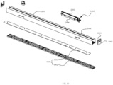
FIG. 10 is an exploded schematic view of the track light of the present embodiment. - A specific embodiment of the present invention will be further described below with reference to the accompanying drawings. It should be understood that the description of the embodiments of the present invention hereinafter is exemplary only but not intended to delimit the scope of the invention.
- As shown in
Figs. 1 to 10 , thetrack adapter 1000 of the present invention can be used alone or can be integrated with a driving power supply, as long as the housing of the driving power supply is defined as themounting seat 100 in the sense of the present invention for fixing and mounting other components of thetrack adapter 1000, and the remaining structure is unchanged. When thetrack adapter 1000 is used alone, it is connected to a light fixture or to the positive and negative poles of a separate driving power supply. The embodiment that will be described hereinafter is illustrated with integration as an example. - The
driving power supply 2000 of the present embodiment includes apower supply housing 2001 and acircuit board 2002 and atrack adapter 1000 disposed in the power supply housing. - The
track adapter 1000 can be used alone and independently with thepower supply housing 2001 and thecircuit board 2002 removed. Thetrack adapter 1000 of the present embodiment includes amounting seat 100, an electrical supply column (power take-off post) 200, an adjustmentconductive portion 300, anadjustment knob 400, and adrive mechanism 500. Themounting seat 100 is used to carry other components, and themounting seat 100 may be thepower supply housing 2001 itself or a component manufactured for manufacturing and mounting. In the present embodiment, themounting seat 100 includes apower supply housing 2001 and amounting piece 103 fixed to thepower supply housing 2001. Themounting seat 100 has a firstcentral axis 101, and theelectrical supply column 200 can be rotated about the firstcentral axis 101 and is arranged on themounting seat 100. Theelectrical supply column 200 has a general structure and configuration that is matched with the track, and it can be inserted into the track groove to implement the electric connection after rotation. Theelectrical supply column 200 is provided with a negative electrodeconductive sheet 201 and at least two positive electrodeconductive sheets 202. In the present invention, the negative electrode and positive electrode are defined as: L and N as the symbols in alternating current, where L is the "fire line" of single-phase alternating current, that is the positive pole, N is the "zero line" of single-phase alternating current, that is the negative pole, and in direct current, "+" represents the positive electrode and "-" represents the negative electrode. For a multi-wire track of the prior art, such as with four wire tracks, which is a standard part, it is generally of U-shaped profile and a plurality of card slots extending on both sides of the U-shaped profile is provided for arranging conductive metal strips L1, conductive metal strip L2, the conductive metal strip L3, and the conductive metal strip N. The conductive metal strips can be arranged on a separate side. There are also other schemes such as the conductive metal strips in different quantities are set on both sides, which is known from the prior art and will not be described hereinafter in more detail. - The negative electrode
conductive sheet 201 and the positive electrodeconductive sheet 202 on theelectrical supply column 200 can be set correspondingly. Theelectrical supply column 200 is extended into the track and rotated to realize the connection and conduction of the negative electrodeconductive sheet 201 and the positive electrodeconductive sheet 202 with the corresponding conductive metal strip. - The negative electrode
conductive sheet 201 needs to be in permanent electrical contact, and it is necessary to choose one of the positive electrodeconductive sheet 202 to conduct, the specific mode being as follows: the positive electrodeconductive sheet 202 extends to the bottom of theelectrical supply column 200 forming apositive electrode contact 2021, and thepositive electrode contacts 2021 are arranged around the firstcentral axis 101 at intervals. The adjustmentconductive portion 300 is located at the bottom of theelectrical supply column 200, and is rotated around the firstcentral axis 101 and arranged on themounting seat 100, and is provided with aconductive contact 301 in flexible connection with the bottom of theelectrical supply column 200. The moving path of theconductive contact 301 passes through (all of) thepositive electrode contacts 2021. When theelectrical supply column 200 is rotated to be connected to the track, theconductive contact 301 is in electric contact with one of thepositive contacts 2021, that is, it conducts with the corresponding conductive metal strip. The flexible connection may be accomplished by abutment or a combination of a plug-in and an annular groove. In order to make theconductive contact 301 conductive with differentpositive electrode contacts 2021, theadjustment knob 400 is rotated and arranged on themounting seat 100 and located on the outside of the top of theelectrical supply column 200. Thedrive mechanism 500 is used to implement (drive) the connection between theadjustment knob 400 and the adjustmentconductive portion 300. By turning theadjustment knob 400, thedrive mechanism 500 will transmit the stroke of theadjustment knob 400 to the adjustmentconductive portion 300, and the adjustmentconductive portion 300 will be adjusted (displaced) to rotate to the designed position, when theelectrical supply column 200 is rotated in place, it will conduct with the required conductive metal strip. - The
adjustment knob 400 of the present embodiment is arranged on the outside of the top of theelectrical supply column 200 facilitating manual adjustment, particularly when thetrack adapter 1000 is installed in a deep and narrow structure. To facilitate external connection, the adjustmentconductive portion 300 may further include a positive electrodeconductive connector 304 and a negative electrodeconductive connector 305 which are fixedly arranged. The positive electrodeconductive connector 304 maintains a constant (permanent) electrical conduction with theconductive contact 301. In this embodiment, the positive electrodeconductive connector 304 maintains a constant conduction with theconductive contact 301 through a conductive ring. When the negative electrodeconductive sheet 201 is rotated to the position of the track connection, the negative electrodeconductive connector 305 is in conduction with the negative electrodeconductive sheet 201. - The
drive mechanism 500 is realized in many forms, such as thread drive, gear transmission, rack transmission, etc. In this embodiment, in order to simplify and facilitate manufacture, the mountingseat 100 is provided with a secondcentral axis 102 parallel to the firstcentral axis 101. Thedrive mechanism 500 includes afirst drive gear 501 and asecond drive gear 502. Thefirst drive gear 501 is located at the bottom of theelectrical supply column 200 and fixedly connected to the adjustmentconductive portion 300, and its gear shaft is coincidence with the firstcentral axis 101; thesecond drive gear 502 is engaged with thefirst drive gear 501 and is rotatable around the secondcentral axis 102 and arranged on the mountingseat 100. Theadjustment knob 400 is fixed to thesecond drive gear 502, and the mountingpiece 103 are provided with two mounting holes for arranging thefirst drive gear 501 and thesecond drive gear 502, where rotational connection is realized through buckle structure. - In order to make the
conductive contact 301 andpositive electrode contact 2021 conduct stably, the bottom of theelectrical supply column 200 is radially expanded to form aconductive plate 203. Thepositive electrode contact 2021 is a sheet attached to the bottom surface of theconductive plate 203, and theconductive contact 301 abuts against the bottom surface of theconductive plate 203. The large contact area of the sheet structure can assist in avoiding the conventional connection instability caused by manufacturing and assembly errors. - The negative electrode
conductive sheet 201 is different from the positive electrodeconductive sheet 202, and it does not need to choose. It only needs to wait for theelectrical supply column 200 to be rotated in place. In order to facilitate integral production, the negative electrodeconductive sheet 201 may extend to the bottom of theelectrical supply column 200 to form anegative electrode contact 2011. In the present embodiment, thenegative electrode contacts 2011 and thepositive electrode contact 2021 are arranged on the same surface and arranged together. - The structure of the adjustment
conductive portion 300 is fitting with the bottom of theelectrical supply column 200. In this embodiment, the adjustmentconductive portion 300 includes anadjustment plate 302 and an annularconductive plate 303. Theadjustment plate 302 is provided with ashaft hole 3021 in the middle, and the plate surface of theadjustment plate 302 faces against (toward) thepositive electrode contact 2021 on the bottom surface of theconductive plate 203 and a throughhole 3022 is provided on the plate surface. The middle of the bottom surface of theconductive plate 203 is provided with arotating shaft 2031 that cooperates with theshaft hole 3021. Tthe annularconductive plate 303 is arranged on the bottom surface of theadjustment plate 302, being with a conductive shrapnel passing through the throughhole 3022 as theconductive contact 301 thereon. - This embodiment is used to cooperate with the common standard parts of a four-wire track. There are three positive electrode
conductive sheets 202 in this embodiment and these are correspondingly connected to the conductive metal strip L1, and the conductive metal strip L2, the conductive metal strip L3 respectively. - In order to facilitate manual installation, in the present embodiment, the
electrical supply column 200 may be provided with a protrudingrotating handle 204. - The above-described
track adapter 1000 can be produced independently, manufactured, and mounted. In this embodiment it is integrated into the driving power supply. More specifically, the mountingseat 100 is fixed to thepower supply housing 2001, and thepower supply housing 2001 has aleft portion 2007 and aright portion 2008. The positive electrodeconductive connector 304 is connected to the positive input end of thecircuit board 2002, the negative electrodeconductive connector 305 is connected to the negative input end of thecircuit board 2002, and the connection method is inserted or welded. - The mounting
seat 100, theadjustment column 200, the adjustmentconductive portion 300 and thedrive mechanism 500 are disposed in thepower supply housing 2001. The top of thepower supply housing 2001 is provided with a mounting hole for theadjustment knob 400 passing through, and at least one side of thepower supply housing 2001 is provided with anelectrical supply hole 2004 that is provided for the negative electrodeconductive sheet 201 and the positive electrodeconductive sheet 202 passing through. There are three positive electrodeconductive sheets 202, which are grouped together in pairs with the negative electrodeconductive sheet 201 and arranged on both sides of theelectric column 200. Thepower supply housing 2001 is provided with anelectrical supply hole 2004 on both sides. - The
track adapter 1000 of this embodiment is particularly useful for a track light of the present embodiment as described in the following. The track light includes alamp holder 3000. Thelamp holder 3000 is provided with alight source assembly 4000, a drivingpower supply 2000, and atrack adapter 1000. The lamp holder driving power supply includes apower supply housing 2001 and acircuit board 2002 disposed in the power supply housing, the mountingseat 100 is fixed to thepower supply housing 2001, the positive electrodeconductive connector 304 is connected to the positive input end of thecircuit board 2002, and the negative electrodeconductive connector 305 is connected to the negative input end of thecircuit board 2002. - The lamp holder of the present embodiment may wrap the whole track, and its design is neat and beautiful. The
lamp holder 3000 includes aU-shaped profile 3001 with opening upward and anend cover 3002 provided at both ends of theU-shaped profile 3001. Thelight source assembly 4000 is arranged on the outer side of theU-shaped profile 3001, thetrack adapter 1000 is arranged in the bottom of theU-shaped profile 3001, and theend cover 3002 is provided with anotch 3003 that avoids the track. - In order to facilitate the installation of the
light source assembly 4000, theU-shaped profile 3001 extends downward on both sides. Thelight source assembly 4000 includes alamp plate 4001 and anoptical element 4002. - The
power supply housing 2001 includes alower portion 2006 and anupper portion 2005 inserted (in particular snapped) into the track. The mountingseat 100, aelectrical supply column 200, and the adjustmentconductive portion 300 and thedrive mechanism 500 are disposed in thepower supply housing 2001. The top of theupper portion 2005 is provided with a mountinghole 2003 for theadjustment knob 400 to be exposed, and both sides are provided with anelectrical supply hole 2004 for the negative electrodeconductive sheet 201 and the positive electrodeconductive sheet 202, respectively, to pass through. - The
upper portion 2005 is stuck in the track, and therefore the width of thelower portion 2006 is larger than theupper portion 2005, for facilitating thedrive mechanism 500 to accommodate the mountingseat 100 and thedrive mechanism 500. - The
electrical supply column 200 is provided with arotating handle 204 extending out of thepower supply housing 2001, and the side wall of theU-shaped profile 3001 is provided with astrip hole 3006 where therotating handle 204 passes through. - The above preferred embodiments of the present invention are not intended to delimit the scope of the invention. Rather, any modifications, equivalents or modifications to the afore-mentioned embodiment provided according to the present invention as outlined above shall be covered by the scope of the accompanying claims.
Claims (14)
- A track adapter (1000), comprising:a mounting seat (100) having a first central axis (101) extending between an upper side and a bottom side of the mounting seat (100);an electrical supply column (200) arranged on the mounting seat (100), wherein the electrical supply column (200) has a top disposed at the upper side of the mounting seat (100) and a bottom disposed at the bottom side of the mounting seat (100), said electrical supply column (200) extending along the first central axis (101) and being rotatable about the first central axis (101), wherein the electrical supply column (200) is provided with a negative electrode conductive sheet (201) and at least two positive electrode conductive sheets (202) on its column body, each positive electrode conductive sheet (202) extending to the bottom of the electrical supply column (200) to form a positive electrode contact (2021), the negative electrode conductive sheet (201) extending to the bottom of the electrical supply column (200) to form a negative electrode contact (2011) and the positive electrode contacts (2021) being arranged around the first central axis (101) at intervals;an adjustment conductive portion (300) located at the bottom of the electrical supply column (200), being rotatable about the first central axis (101) and arranged on the mounting seat (100), said adjustment conductive portion (300) being provided with a conductive contact (301) in flexible connection with the bottom of the electrical supply column (200), wherein a moving path of the conductive contact (301) passes through the positive electrode contacts (2021); and adrive mechanism (500) configured for driving a rotation of the electrical supply column (200) about the first central axis (101); whereinthe adjustment conductive portion (300) comprisesa positive electrode conductive connector (304) configured to electrically connect with each of the at least two positive electrode conductive sheets (202) via one ofthe positive electrode contacts (2021); anda negative electrode conductive connector (305) configured to electrically connect with the negative electrode conductive sheet (201) via the negative electrode contact (2011) when the negative electrode conductive sheet (201) is rotated to a connection position;characterized in thatthe drive mechanism (500) comprises:a first drive gear (501), which is located at the bottom of the electrical supply column (200) and connected to the adjustment conductive portion (300), with its gear shaft being coincident with the first central axis (101); anda second drive gear (502), which is engaged with the first drive gear (501), rotatable about a second central axis (102) extending in parallel with the first central axis (101) and arranged on the mounting seat (100); whereinthe track adapter (1000) defines a longitudinal axis being perpendicular to the first and second central axis (101, 102),the first and second drive gear (501, 502) are disposed spaced apart to each other along the longitudinal axis of the track adapter (1000), andan adjustment knob (400) is fixedly connected to the second drive gear (502) to be rotatably arranged on the mounting seat (100) so that the adjustment knob (400) is located on the outside of the top of the electrical supply column (200) and the drive mechanism (500) implements a drive connection between the adjustment knob (400) and the adjustment conductive portion (300).
- The track adapter (1000) as claimed in claim 1, wherein the bottom of the electrical supply column (200) is radially expanded to form a conductive plate (203), wherein each positive electrode contact (2021) is in the form of a sheet attached to a bottom surface of the conductive plate (203), and the conductive contact (301) abuts against the bottom surface of the conductive plate (203).
- The track adapter (1000) as claimed in claim 2, wherein the adjustment conductive portion (300) comprises:an adjustment plate (302), provided with a shaft hole (3021) in the middle, wherein a plate surface of the adjustment plate (302) faces against the positive electrode contacts (2021) on the bottom surface of the conductive plate (203) and a through hole (3022) is provided on the plate surface, and wherein a rotating shaft (2031) is provided at the center of the bottom surface of the conductive plate (203) that cooperates with the shaft hole (3021);and an annular conductive plate (303), which is arranged on the bottom surface of the adjustment plate (302), with a conductive shrapnel passing through the through hole (3022) as the conductive contact (301) thereon.
- The track adapter (1000) as claimed in any of the preceding claims, wherein there are three positive electrode conductive sheets (202).
- The track adapter (1000) as claimed in any of the preceding claims, wherein the electrical supply column (200) is provided with a protruding rotating handle (204).
- A driving power supply (2000) comprising a power supply housing (2001) and a circuit board (2002) disposed in the power supply housing,characterized by thetrack adapter (1000) as claimed in any of the preceding claims, whereinthe mounting seat (100) is fixed to the power supply housing (2001),the positive electrode conductive connector (304) is connected to a positive input end of the circuit board (2002), andthe negative electrode conductive connector (305) is connected to a negative input end of the circuit board (2002).
- The driving power supply (2000) as claimed in claim 6, whereinthe mounting seat (100), the adjustment column (200), the adjustment conductive portion (300) and the drive mechanism (500) are disposed in the power supply housing (2001),a top of the power supply housing (2001) is provided with a mounting hole for the adjustment knob (400) passing through, andat least one side of the power supply housing (2001) is provided with an electrical supply hole (2004) that is provided for the negative electrode conductive sheet (201) and the positive electrode conductive sheet (202) passing through.
- The driving power supply (2000) as claimed in claim 6 or 7, whereinthere are three positive electrode conductive sheets (202), which are grouped together in pairs with the negative electrode conductive sheet (201) and arranged on both sides of the electric column (200), andthe power supply housing (2001) is provided with an electrical supply hole (2004) on both sides.
- A track light comprises a lamp holder (3000), comprising a light source assembly (4000), adriving power supply (2000), and thetrack adapter (1000) as claimed in any of claims 1 to 5, which are arranged on the lamp holder (3000).
- The track light as claimed in claim 9, whereinthe lamp holder driving power supply includes a power supply housing (2001) and a circuit board (2002) disposed in the power supply housing,the mounting seat (100) is fixed to the power supply housing (2001),the positive electrode conductive connector (304) is connected to the positive input end of the circuit board (2002), andthe negative electrode conductive connector (305) is connected to the negative input end of the circuit board (2002).
- The track light as claimed in claim 9 or 10, whereinthe lamp holder (3000) includes a U-shaped profile (3001) with an opening upward and an end cover (3002) provided at both ends of the U-shaped profile (3001), andthe light source assembly (4000) is arranged on the outer side of the U-shaped profile (3001), the track adapter (1000) being arranged in the bottom of the U-shaped profile (3001); andthe end cover (3002) is provided with a notch (3003) to avoid the track.
- The track light as claimed in claim 9, whereinthe power supply housing (2001) comprises a lower portion (2006) and an upper portion (2005) inserted into the track,the mounting seat (100), the electrical supply column (200), the adjustment conductive portion (300) and the drive mechanism (500) are disposed in the power supply housing (2001),the top of the upper portion (2005) is provided with a mounting hole (2003) so that the adjustment knob (400) is exposed, andthe two sides are provided with the electrical supply hole (2004) that is provided for the negative electrode conductive sheet (201) and the positive electrode conductive sheet (202) to pass through.
- The track light as claimed in claim 12, wherein the width of the lower portion (2006) is
greater than the width of the upper portion (2005), for facilitating the drive mechanism (500) to accommodate the mounting seat (100) and the drive mechanism (500). - The track light as claimed in any of claims 9 to 13, whereinthe electrical supply column (200) is provided with a rotating handle (204) extending out of the power supply housing (2001), andthe side wall of the U-shaped profile (3001) is provided with a strip hole (3006) where the rotating handle (204) passes through.
Applications Claiming Priority (1)
| Application Number | Priority Date | Filing Date | Title |
|---|---|---|---|
| CN202011488890.7A CN112503489B (en) | 2020-12-16 | 2020-12-16 | Track adapter, driving power supply with the adapter, and track light |
Publications (2)
| Publication Number | Publication Date |
|---|---|
| EP4016758A1 EP4016758A1 (en) | 2022-06-22 |
| EP4016758B1 true EP4016758B1 (en) | 2024-10-23 |
Family
ID=74972833
Family Applications (1)
| Application Number | Title | Priority Date | Filing Date |
|---|---|---|---|
| EP21183159.9A Active EP4016758B1 (en) | 2020-12-16 | 2021-07-01 | A track adapter and the driving power supply and track light thereof |
Country Status (3)
| Country | Link |
|---|---|
| US (1) | US11441761B2 (en) |
| EP (1) | EP4016758B1 (en) |
| CN (1) | CN112503489B (en) |
Families Citing this family (6)
| Publication number | Priority date | Publication date | Assignee | Title |
|---|---|---|---|---|
| USD1007034S1 (en) * | 2020-10-29 | 2023-12-05 | Self Electronics Co., Ltd. | Strip track light |
| CN114361834A (en) * | 2021-12-14 | 2022-04-15 | 东莞天盛电子制品有限公司 | Power connection switching assembly, power connection box, track lamp power transmission device and switching method |
| CN114263867B (en) * | 2021-12-24 | 2025-03-11 | 东莞天盛电子制品有限公司 | Insulating spacer, push-type switching assembly, track connection device and switching method |
| CN115313113A (en) * | 2022-07-26 | 2022-11-08 | 浙江澳瑞克斯电子有限公司 | An adapter for rail socket |
| CN221349050U (en) * | 2023-11-09 | 2024-07-16 | 晨辉光宝科技股份有限公司 | Adjustable track lamp |
| CN118423655B (en) * | 2024-07-02 | 2024-11-05 | 佛山汉盾光电科技有限公司 | A power rail head for embedded lighting fixtures |
Family Cites Families (12)
| Publication number | Priority date | Publication date | Assignee | Title |
|---|---|---|---|---|
| DE102008059354A1 (en) * | 2008-11-25 | 2010-05-27 | Keiper Gmbh & Co. Kg | Drive unit for a vehicle seat |
| DE202008015676U1 (en) * | 2008-11-26 | 2009-02-19 | Sun-Lite Sockets Industry Inc., Kuei Shan Hsiang | Triple, light-regulating lamp socket |
| US9929554B2 (en) * | 2014-06-25 | 2018-03-27 | Amazon Technologies, Inc. | Power busway interposer |
| US10690329B2 (en) * | 2017-01-05 | 2020-06-23 | Modulex Inc. | Power supply box device |
| US11223175B2 (en) * | 2018-02-28 | 2022-01-11 | Modulex Inc. | Plug for use in a wiring duct |
| EP3544127B1 (en) * | 2018-03-21 | 2021-11-10 | Eutrac Stromschienen GmbH | Busbar adapter, arrangement comprising a conductor rail and method for connecting a conductor rail adapter in a conductor rail |
| DE202018003149U1 (en) * | 2018-07-06 | 2018-08-03 | Sunrise Power Transformers Gmbh | A novel combined rail lighting structure comprising a lamp holder for mounting an LED lamp and a guide rail for moving the lamp holder |
| US11187389B2 (en) * | 2019-07-25 | 2021-11-30 | Lighting Services, Inc. | LED track element for track lighting systems |
| CN211146219U (en) * | 2019-12-09 | 2020-07-31 | 中山市智观照明科技有限公司 | Track driving connector and track lamp using same |
| IT201900023634A1 (en) * | 2019-12-11 | 2021-06-11 | A A G Stucchi S R L U S | Connection device with mobile control device |
| GB2590510B (en) * | 2019-12-20 | 2022-12-07 | Thorn Lighting Ltd | Longitudinal luminaire with alignment features |
| CN215061917U (en) * | 2020-12-16 | 2021-12-07 | 赛尔富电子有限公司 | Track adapter, driving power supply with same and track lamp |
-
2020
- 2020-12-16 CN CN202011488890.7A patent/CN112503489B/en active Active
-
2021
- 2021-06-29 US US17/305,003 patent/US11441761B2/en active Active
- 2021-07-01 EP EP21183159.9A patent/EP4016758B1/en active Active
Also Published As
| Publication number | Publication date |
|---|---|
| EP4016758A1 (en) | 2022-06-22 |
| CN112503489A (en) | 2021-03-16 |
| CN112503489B (en) | 2025-07-11 |
| US11441761B2 (en) | 2022-09-13 |
| US20220186918A1 (en) | 2022-06-16 |
Similar Documents
| Publication | Publication Date | Title |
|---|---|---|
| EP4016758A1 (en) | A track adapter and the driving power supply and track light thereof | |
| EP4027467B1 (en) | A track adapter and the driving power supply and track light thereof | |
| US11715995B2 (en) | Power tool | |
| US5137051A (en) | Control device for a radiator valve | |
| US20230211489A1 (en) | Power tool | |
| US20040188119A1 (en) | Portable electric-powered tool | |
| US20110318976A1 (en) | Universal termination system for power tools | |
| MXPA06000972A (en) | Rocker paddle switch with semi-rigid cam driver. | |
| CA3070983A1 (en) | Bracket, functional module, mounting method of electrical device and the electrical device | |
| CN215061917U (en) | Track adapter, driving power supply with same and track lamp | |
| EP0917170B1 (en) | Operating mechanism of rotary electric component | |
| EP1874585B1 (en) | Relay connector | |
| CN214672057U (en) | Quick connect variable resistor | |
| CN223345336U (en) | Electrodeless cutting structure and stage lamp thereof | |
| CN223147072U (en) | Electric tool | |
| CN221127065U (en) | Stator assembly, motor and impact wrench | |
| CN222376773U (en) | A building block computer fan and a series of building block computer fan sets | |
| CN221552397U (en) | Power rail and power distribution device | |
| JP3072855U (en) | Switch structure in table tap | |
| CN111739757B (en) | Integrated multipurpose panel switch | |
| CN212361797U (en) | A hidden guide rail linear light | |
| EP0569659A2 (en) | Integrated terminal block fixedly associated with a plug | |
| JP2025179773A (en) | Stepping dimming motor structure | |
| EP3392558B1 (en) | Led light fixture and method of mounting thereof | |
| JP3700206B2 (en) | Appliance housing |
Legal Events
| Date | Code | Title | Description |
|---|---|---|---|
| PUAI | Public reference made under article 153(3) epc to a published international application that has entered the european phase |
Free format text: ORIGINAL CODE: 0009012 |
|
| STAA | Information on the status of an ep patent application or granted ep patent |
Free format text: STATUS: THE APPLICATION HAS BEEN PUBLISHED |
|
| AK | Designated contracting states |
Kind code of ref document: A1 Designated state(s): AL AT BE BG CH CY CZ DE DK EE ES FI FR GB GR HR HU IE IS IT LI LT LU LV MC MK MT NL NO PL PT RO RS SE SI SK SM TR |
|
| STAA | Information on the status of an ep patent application or granted ep patent |
Free format text: STATUS: REQUEST FOR EXAMINATION WAS MADE |
|
| 17P | Request for examination filed |
Effective date: 20221221 |
|
| RBV | Designated contracting states (corrected) |
Designated state(s): AL AT BE BG CH CY CZ DE DK EE ES FI FR GB GR HR HU IE IS IT LI LT LU LV MC MK MT NL NO PL PT RO RS SE SI SK SM TR |
|
| GRAP | Despatch of communication of intention to grant a patent |
Free format text: ORIGINAL CODE: EPIDOSNIGR1 |
|
| STAA | Information on the status of an ep patent application or granted ep patent |
Free format text: STATUS: GRANT OF PATENT IS INTENDED |
|
| RIC1 | Information provided on ipc code assigned before grant |
Ipc: H01R 24/38 20110101ALN20240422BHEP Ipc: H01R 25/14 20060101ALI20240422BHEP Ipc: H01R 13/71 20060101AFI20240422BHEP |
|
| INTG | Intention to grant announced |
Effective date: 20240513 |
|
| GRAS | Grant fee paid |
Free format text: ORIGINAL CODE: EPIDOSNIGR3 |
|
| GRAA | (expected) grant |
Free format text: ORIGINAL CODE: 0009210 |
|
| STAA | Information on the status of an ep patent application or granted ep patent |
Free format text: STATUS: THE PATENT HAS BEEN GRANTED |
|
| AK | Designated contracting states |
Kind code of ref document: B1 Designated state(s): AL AT BE BG CH CY CZ DE DK EE ES FI FR GB GR HR HU IE IS IT LI LT LU LV MC MK MT NL NO PL PT RO RS SE SI SK SM TR |
|
| REG | Reference to a national code |
Ref country code: GB Ref legal event code: FG4D |
|
| REG | Reference to a national code |
Ref country code: CH Ref legal event code: EP |
|
| REG | Reference to a national code |
Ref country code: DE Ref legal event code: R096 Ref document number: 602021020551 Country of ref document: DE |
|
| REG | Reference to a national code |
Ref country code: IE Ref legal event code: FG4D |
|
| REG | Reference to a national code |
Ref country code: LT Ref legal event code: MG9D |
|
| REG | Reference to a national code |
Ref country code: NL Ref legal event code: MP Effective date: 20241023 |
|
| REG | Reference to a national code |
Ref country code: AT Ref legal event code: MK05 Ref document number: 1735625 Country of ref document: AT Kind code of ref document: T Effective date: 20241023 |
|
| PG25 | Lapsed in a contracting state [announced via postgrant information from national office to epo] |
Ref country code: NL Free format text: LAPSE BECAUSE OF FAILURE TO SUBMIT A TRANSLATION OF THE DESCRIPTION OR TO PAY THE FEE WITHIN THE PRESCRIBED TIME-LIMIT Effective date: 20241023 |
|
| PG25 | Lapsed in a contracting state [announced via postgrant information from national office to epo] |
Ref country code: NL Free format text: LAPSE BECAUSE OF FAILURE TO SUBMIT A TRANSLATION OF THE DESCRIPTION OR TO PAY THE FEE WITHIN THE PRESCRIBED TIME-LIMIT Effective date: 20241023 |
|
| PG25 | Lapsed in a contracting state [announced via postgrant information from national office to epo] |
Ref country code: PT Free format text: LAPSE BECAUSE OF FAILURE TO SUBMIT A TRANSLATION OF THE DESCRIPTION OR TO PAY THE FEE WITHIN THE PRESCRIBED TIME-LIMIT Effective date: 20250224 Ref country code: IS Free format text: LAPSE BECAUSE OF FAILURE TO SUBMIT A TRANSLATION OF THE DESCRIPTION OR TO PAY THE FEE WITHIN THE PRESCRIBED TIME-LIMIT Effective date: 20250223 Ref country code: HR Free format text: LAPSE BECAUSE OF FAILURE TO SUBMIT A TRANSLATION OF THE DESCRIPTION OR TO PAY THE FEE WITHIN THE PRESCRIBED TIME-LIMIT Effective date: 20241023 |
|
| PG25 | Lapsed in a contracting state [announced via postgrant information from national office to epo] |
Ref country code: FI Free format text: LAPSE BECAUSE OF FAILURE TO SUBMIT A TRANSLATION OF THE DESCRIPTION OR TO PAY THE FEE WITHIN THE PRESCRIBED TIME-LIMIT Effective date: 20241023 |
|
| PG25 | Lapsed in a contracting state [announced via postgrant information from national office to epo] |
Ref country code: BG Free format text: LAPSE BECAUSE OF FAILURE TO SUBMIT A TRANSLATION OF THE DESCRIPTION OR TO PAY THE FEE WITHIN THE PRESCRIBED TIME-LIMIT Effective date: 20241023 |
|
| PG25 | Lapsed in a contracting state [announced via postgrant information from national office to epo] |
Ref country code: ES Free format text: LAPSE BECAUSE OF FAILURE TO SUBMIT A TRANSLATION OF THE DESCRIPTION OR TO PAY THE FEE WITHIN THE PRESCRIBED TIME-LIMIT Effective date: 20241023 |
|
| PG25 | Lapsed in a contracting state [announced via postgrant information from national office to epo] |
Ref country code: NO Free format text: LAPSE BECAUSE OF FAILURE TO SUBMIT A TRANSLATION OF THE DESCRIPTION OR TO PAY THE FEE WITHIN THE PRESCRIBED TIME-LIMIT Effective date: 20250123 |
|
| PG25 | Lapsed in a contracting state [announced via postgrant information from national office to epo] |
Ref country code: LV Free format text: LAPSE BECAUSE OF FAILURE TO SUBMIT A TRANSLATION OF THE DESCRIPTION OR TO PAY THE FEE WITHIN THE PRESCRIBED TIME-LIMIT Effective date: 20241023 Ref country code: AT Free format text: LAPSE BECAUSE OF FAILURE TO SUBMIT A TRANSLATION OF THE DESCRIPTION OR TO PAY THE FEE WITHIN THE PRESCRIBED TIME-LIMIT Effective date: 20241023 Ref country code: GR Free format text: LAPSE BECAUSE OF FAILURE TO SUBMIT A TRANSLATION OF THE DESCRIPTION OR TO PAY THE FEE WITHIN THE PRESCRIBED TIME-LIMIT Effective date: 20250124 |
|
| PG25 | Lapsed in a contracting state [announced via postgrant information from national office to epo] |
Ref country code: PL Free format text: LAPSE BECAUSE OF FAILURE TO SUBMIT A TRANSLATION OF THE DESCRIPTION OR TO PAY THE FEE WITHIN THE PRESCRIBED TIME-LIMIT Effective date: 20241023 |
|
| PG25 | Lapsed in a contracting state [announced via postgrant information from national office to epo] |
Ref country code: RS Free format text: LAPSE BECAUSE OF FAILURE TO SUBMIT A TRANSLATION OF THE DESCRIPTION OR TO PAY THE FEE WITHIN THE PRESCRIBED TIME-LIMIT Effective date: 20250123 |
|
| PG25 | Lapsed in a contracting state [announced via postgrant information from national office to epo] |
Ref country code: SM Free format text: LAPSE BECAUSE OF FAILURE TO SUBMIT A TRANSLATION OF THE DESCRIPTION OR TO PAY THE FEE WITHIN THE PRESCRIBED TIME-LIMIT Effective date: 20241023 |
|
| PG25 | Lapsed in a contracting state [announced via postgrant information from national office to epo] |
Ref country code: DK Free format text: LAPSE BECAUSE OF FAILURE TO SUBMIT A TRANSLATION OF THE DESCRIPTION OR TO PAY THE FEE WITHIN THE PRESCRIBED TIME-LIMIT Effective date: 20241023 |
|
| PG25 | Lapsed in a contracting state [announced via postgrant information from national office to epo] |
Ref country code: EE Free format text: LAPSE BECAUSE OF FAILURE TO SUBMIT A TRANSLATION OF THE DESCRIPTION OR TO PAY THE FEE WITHIN THE PRESCRIBED TIME-LIMIT Effective date: 20241023 |
|
| PG25 | Lapsed in a contracting state [announced via postgrant information from national office to epo] |
Ref country code: RO Free format text: LAPSE BECAUSE OF FAILURE TO SUBMIT A TRANSLATION OF THE DESCRIPTION OR TO PAY THE FEE WITHIN THE PRESCRIBED TIME-LIMIT Effective date: 20241023 |
|
| REG | Reference to a national code |
Ref country code: DE Ref legal event code: R097 Ref document number: 602021020551 Country of ref document: DE |
|
| PG25 | Lapsed in a contracting state [announced via postgrant information from national office to epo] |
Ref country code: SK Free format text: LAPSE BECAUSE OF FAILURE TO SUBMIT A TRANSLATION OF THE DESCRIPTION OR TO PAY THE FEE WITHIN THE PRESCRIBED TIME-LIMIT Effective date: 20241023 |
|
| PG25 | Lapsed in a contracting state [announced via postgrant information from national office to epo] |
Ref country code: CZ Free format text: LAPSE BECAUSE OF FAILURE TO SUBMIT A TRANSLATION OF THE DESCRIPTION OR TO PAY THE FEE WITHIN THE PRESCRIBED TIME-LIMIT Effective date: 20241023 |
|
| PG25 | Lapsed in a contracting state [announced via postgrant information from national office to epo] |
Ref country code: IT Free format text: LAPSE BECAUSE OF FAILURE TO SUBMIT A TRANSLATION OF THE DESCRIPTION OR TO PAY THE FEE WITHIN THE PRESCRIBED TIME-LIMIT Effective date: 20241023 |
|
| PLBE | No opposition filed within time limit |
Free format text: ORIGINAL CODE: 0009261 |
|
| STAA | Information on the status of an ep patent application or granted ep patent |
Free format text: STATUS: NO OPPOSITION FILED WITHIN TIME LIMIT |
|
| PG25 | Lapsed in a contracting state [announced via postgrant information from national office to epo] |
Ref country code: SE Free format text: LAPSE BECAUSE OF FAILURE TO SUBMIT A TRANSLATION OF THE DESCRIPTION OR TO PAY THE FEE WITHIN THE PRESCRIBED TIME-LIMIT Effective date: 20241023 |
|
| 26N | No opposition filed |
Effective date: 20250724 |
|
| PGFP | Annual fee paid to national office [announced via postgrant information from national office to epo] |
Ref country code: DE Payment date: 20250731 Year of fee payment: 5 |
|
| REG | Reference to a national code |
Ref country code: CH Ref legal event code: H13 Free format text: ST27 STATUS EVENT CODE: U-0-0-H10-H13 (AS PROVIDED BY THE NATIONAL OFFICE) Effective date: 20260224 |
|
| PG25 | Lapsed in a contracting state [announced via postgrant information from national office to epo] |
Ref country code: LU Free format text: LAPSE BECAUSE OF NON-PAYMENT OF DUE FEES Effective date: 20250701 |
|
| GBPC | Gb: european patent ceased through non-payment of renewal fee |
Effective date: 20250701 |
|
| REG | Reference to a national code |
Ref country code: BE Ref legal event code: MM Effective date: 20250731 |
|
| PG25 | Lapsed in a contracting state [announced via postgrant information from national office to epo] |
Ref country code: GB Free format text: LAPSE BECAUSE OF NON-PAYMENT OF DUE FEES Effective date: 20250701 |
|
| PG25 | Lapsed in a contracting state [announced via postgrant information from national office to epo] |
Ref country code: BE Free format text: LAPSE BECAUSE OF NON-PAYMENT OF DUE FEES Effective date: 20250731 |
|
| PG25 | Lapsed in a contracting state [announced via postgrant information from national office to epo] |
Ref country code: FR Free format text: LAPSE BECAUSE OF NON-PAYMENT OF DUE FEES Effective date: 20250731 |
|
| PG25 | Lapsed in a contracting state [announced via postgrant information from national office to epo] |
Ref country code: CH Free format text: LAPSE BECAUSE OF NON-PAYMENT OF DUE FEES Effective date: 20250731 |