EP4016747A1 - Connector - Google Patents
Connector Download PDFInfo
- Publication number
- EP4016747A1 EP4016747A1 EP21204617.1A EP21204617A EP4016747A1 EP 4016747 A1 EP4016747 A1 EP 4016747A1 EP 21204617 A EP21204617 A EP 21204617A EP 4016747 A1 EP4016747 A1 EP 4016747A1
- Authority
- EP
- European Patent Office
- Prior art keywords
- connector
- flat cable
- spring
- plate
- spring portion
- Prior art date
- Legal status (The legal status is an assumption and is not a legal conclusion. Google has not performed a legal analysis and makes no representation as to the accuracy of the status listed.)
- Granted
Links
Images






Classifications
-
- H—ELECTRICITY
- H01—ELECTRIC ELEMENTS
- H01R—ELECTRICALLY-CONDUCTIVE CONNECTIONS; STRUCTURAL ASSOCIATIONS OF A PLURALITY OF MUTUALLY-INSULATED ELECTRICAL CONNECTING ELEMENTS; COUPLING DEVICES; CURRENT COLLECTORS
- H01R12/00—Structural associations of a plurality of mutually-insulated electrical connecting elements, specially adapted for printed circuits, e.g. printed circuit boards [PCB], flat or ribbon cables, or like generally planar structures, e.g. terminal strips, terminal blocks; Coupling devices specially adapted for printed circuits, flat or ribbon cables, or like generally planar structures; Terminals specially adapted for contact with, or insertion into, printed circuits, flat or ribbon cables, or like generally planar structures
- H01R12/70—Coupling devices
- H01R12/7005—Guiding, mounting, polarizing or locking means; Extractors
- H01R12/7011—Locking or fixing a connector to a PCB
- H01R12/7017—Snap means
-
- H—ELECTRICITY
- H01—ELECTRIC ELEMENTS
- H01R—ELECTRICALLY-CONDUCTIVE CONNECTIONS; STRUCTURAL ASSOCIATIONS OF A PLURALITY OF MUTUALLY-INSULATED ELECTRICAL CONNECTING ELEMENTS; COUPLING DEVICES; CURRENT COLLECTORS
- H01R12/00—Structural associations of a plurality of mutually-insulated electrical connecting elements, specially adapted for printed circuits, e.g. printed circuit boards [PCB], flat or ribbon cables, or like generally planar structures, e.g. terminal strips, terminal blocks; Coupling devices specially adapted for printed circuits, flat or ribbon cables, or like generally planar structures; Terminals specially adapted for contact with, or insertion into, printed circuits, flat or ribbon cables, or like generally planar structures
- H01R12/50—Fixed connections
- H01R12/59—Fixed connections for flexible printed circuits, flat or ribbon cables or like structures
- H01R12/65—Fixed connections for flexible printed circuits, flat or ribbon cables or like structures characterised by the terminal
-
- H—ELECTRICITY
- H01—ELECTRIC ELEMENTS
- H01R—ELECTRICALLY-CONDUCTIVE CONNECTIONS; STRUCTURAL ASSOCIATIONS OF A PLURALITY OF MUTUALLY-INSULATED ELECTRICAL CONNECTING ELEMENTS; COUPLING DEVICES; CURRENT COLLECTORS
- H01R12/00—Structural associations of a plurality of mutually-insulated electrical connecting elements, specially adapted for printed circuits, e.g. printed circuit boards [PCB], flat or ribbon cables, or like generally planar structures, e.g. terminal strips, terminal blocks; Coupling devices specially adapted for printed circuits, flat or ribbon cables, or like generally planar structures; Terminals specially adapted for contact with, or insertion into, printed circuits, flat or ribbon cables, or like generally planar structures
- H01R12/70—Coupling devices
- H01R12/77—Coupling devices for flexible printed circuits, flat or ribbon cables or like structures
- H01R12/771—Details
- H01R12/772—Strain relieving means
-
- H—ELECTRICITY
- H01—ELECTRIC ELEMENTS
- H01R—ELECTRICALLY-CONDUCTIVE CONNECTIONS; STRUCTURAL ASSOCIATIONS OF A PLURALITY OF MUTUALLY-INSULATED ELECTRICAL CONNECTING ELEMENTS; COUPLING DEVICES; CURRENT COLLECTORS
- H01R13/00—Details of coupling devices of the kinds covered by groups H01R12/70 or H01R24/00 - H01R33/00
- H01R13/62—Means for facilitating engagement or disengagement of coupling parts or for holding them in engagement
- H01R13/629—Additional means for facilitating engagement or disengagement of coupling parts, e.g. aligning or guiding means, levers, gas pressure electrical locking indicators, manufacturing tolerances
- H01R13/631—Additional means for facilitating engagement or disengagement of coupling parts, e.g. aligning or guiding means, levers, gas pressure electrical locking indicators, manufacturing tolerances for engagement only
-
- H—ELECTRICITY
- H01—ELECTRIC ELEMENTS
- H01R—ELECTRICALLY-CONDUCTIVE CONNECTIONS; STRUCTURAL ASSOCIATIONS OF A PLURALITY OF MUTUALLY-INSULATED ELECTRICAL CONNECTING ELEMENTS; COUPLING DEVICES; CURRENT COLLECTORS
- H01R12/00—Structural associations of a plurality of mutually-insulated electrical connecting elements, specially adapted for printed circuits, e.g. printed circuit boards [PCB], flat or ribbon cables, or like generally planar structures, e.g. terminal strips, terminal blocks; Coupling devices specially adapted for printed circuits, flat or ribbon cables, or like generally planar structures; Terminals specially adapted for contact with, or insertion into, printed circuits, flat or ribbon cables, or like generally planar structures
- H01R12/70—Coupling devices
- H01R12/77—Coupling devices for flexible printed circuits, flat or ribbon cables or like structures
- H01R12/778—Coupling parts carrying sockets, clips or analogous counter-contacts
-
- H—ELECTRICITY
- H01—ELECTRIC ELEMENTS
- H01R—ELECTRICALLY-CONDUCTIVE CONNECTIONS; STRUCTURAL ASSOCIATIONS OF A PLURALITY OF MUTUALLY-INSULATED ELECTRICAL CONNECTING ELEMENTS; COUPLING DEVICES; CURRENT COLLECTORS
- H01R12/00—Structural associations of a plurality of mutually-insulated electrical connecting elements, specially adapted for printed circuits, e.g. printed circuit boards [PCB], flat or ribbon cables, or like generally planar structures, e.g. terminal strips, terminal blocks; Coupling devices specially adapted for printed circuits, flat or ribbon cables, or like generally planar structures; Terminals specially adapted for contact with, or insertion into, printed circuits, flat or ribbon cables, or like generally planar structures
- H01R12/70—Coupling devices
- H01R12/77—Coupling devices for flexible printed circuits, flat or ribbon cables or like structures
- H01R12/79—Coupling devices for flexible printed circuits, flat or ribbon cables or like structures connecting to rigid printed circuits or like structures
Definitions
- the present invention relates to a connector connectable to a counterpart connector having pin terminals and attachable to a flat cable at an end thereof having lands for electrical contacts.
- Figs. 1 and 2 show a plug connector 10 described in Japanese Registered Patent No. 6664111 as a prior art of this type of connector. Specifically, Fig. 1 shows an aspect in which the plug connector 10 is attached to a flexible flat cable (FPC) 20, and Fig. 2 shows the plug connector 10 attached to the FPC 20, together with a receptacle connector 30 into which the plug connector 10 is to be fitted.
- FPC flexible flat cable
- the plug connector 10 includes a rectangular parallelepiped plug housing 11 and plug terminals 12 housed inside the plug housing 11.
- the plug terminals 12 are arranged in a row laterally (in a horizontal direction) in the plug housing 11.
- the FPC 20 includes FPC terminals 23 which are formed by exposing conductor layers 22 in a connection region 21 to be connected to the plug connector 10. Coupling parts 12a of the plug terminals 12 are located on and soldered to the FPC terminals 23, whereby the plug terminals 12 of the plug connector 10 are connected to the FPC terminals 23 of the FPC 20.
- the plug terminals 12 of the plug connector 10 and the FPC terminals 23 of the FPC 20 are all connected by soldering.
- the coupling parts 12a of all the plug terminals 12 to the FPC terminals 23 the coplanarity of the coupling parts 12a of the plug terminals 12 is a major factor, and in that respect, such a soldering-based connection is not good in workability.
- an object of the present invention is to provide a connector which is attachable to an end of a flat cable and can be easily connected to the flat cable.
- the flat cable means a deformable sheet-shaped cable such as a flexible printed circuit board (FPC) cable or a flexible flat cable (FFC), and these cables are generically named as "flat cable”.
- the connector of the present invention is a connector that is connectable to a counterpart connector having a pin terminal and is attachable to a flat cable at an end thereof having a land for an electrical contact.
- the connector includes a housing and a socket terminal.
- the housing includes a plate-shaped portion and a terminal accommodating portion continuous with the plate-shaped portion.
- the terminal accommodating portion has an accommodating hole.
- the accommodating hole penetrates through the terminal accommodating portion and has an end that is open to the plate-shaped portion.
- the accommodating hole holds the socket terminal inside thereof.
- the socket terminal includes a box portion and a spring portion.
- the box portion is used for receiving the pin terminal of the counterpart connector.
- the box portion will be in direct contact with the pin terminal of the counterpart connector.
- the spring portion has a cantilever shape and extends from the box portion, through the end of the accommodating hole, onto the plate-shaped portion.
- the spring portion separates, in response to insertion of the end of the flat cable into the connector, from the plate-shaped portion in order to make space for the end of the flat cable, make contact with the land of the flat cable after the insertion of the end of the flat cable, and furthermore make contact with the terminal accommodating portion to transmit to the terminal accommodating portion part of force that the spring portion receives from the end of the flat cable.
- the accommodating hole of the terminal accommodating portion has, at an inner surface thereof, a protrusion protruding from the inner surface.
- the protrusion serves as a supporter to give the spring portion a support point that is located between, exclusively, a base end of the spring portion and a free end of the spring portion, and receives the part of force that the spring portion receives from the flat cable.
- the base end of the spring portion serves as a so-called "fixed end" regardless of the insertion of the end of the flat cable.
- the contact between the spring portion and the protrusion which will be caused by the insertion of the end of the flat cable into the connector, will provide the cantilever -- that is, the spring portionwith the new support point and effect changes in the leverage of the cantilever.
- the spring portion has a bridge cut mark that is located between, exclusively, the base end of the spring portion and a contact portion of the spring portion.
- the contact portion is used for a contact with the land.
- the contact portion in whole is plated.
- the bridge cut mark is an evidence of cutting of a bridge that is used for connecting the socket terminal to another socket terminal in a manufacturing process of the socket terminal.
- the spring portion has a wider width at the bridge cut mark, and preferably has, at the bridge cut mark, a width wider than that of the rest of the spring portion.
- attachment of the connector to a flat cable and the electrical connection between a socket terminal of the connector and a land of the flat cable can be performed by inserting the flat cable into the connector, so that a work for connecting to the flat cable can be extremely simply performed.
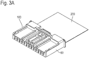
- FIGs. 3A , 3B , 4 and 5A show an embodiment of a connector according to the present invention which is attached to a terminal of an FPC (FPC cable).
- a connector 100 comprises a housing 40, socket terminals 50, and a cover 60.
- the FPC 200 is configured such that a reinforcing plate 210 is attached to a terminal to be connected to the connector 100.
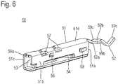
- Fig. 6 shows the details of a socket terminal 50
- Figs. 7A , 7B , 8A and 8B show an aspect in which assembly of the connector 100 and attachment of the connector 100 to the terminal of the FPC 200 are performed in order.
- the socket terminal 50 comprises a box part 51 having a square tubular outer shape into which a pin terminal of a counterpart connector is to be inserted, and a spring piece 52 having a cantilever shape, the spring piece 52 extending rearward from a rear end 51a of the box part 51.
- a pair of internal spring pieces 53 and 54 are provided inside the box part 51 so as to be arranged in a front-rear direction of the box part 51, and so that free ends thereof overlap each other.
- These internal spring pieces 53 and 54 are bent and extended from a lower end side of one side wall 51b of the box part 51.
- two protruding parts 55 protruding to the inner surface side are formed on an upper plate part 51d of the box part 51, and the inner spring piece 53 whose spring force is reinforced by these protruding parts 55 and the internal spring piece 54 serves as a contact part which contacts the pin terminal of the counterpart connector inserted into the box part 51 while pinching the pin terminal of the counterpart connector.
- Windows 56 for checking the position (height position) of the internal spring piece 53 are formed on a pair of side walls 51b and 51c of the box part 51, and two windows 57 for checking the heights of the two protruding parts 55 are formed at each of corner portions formed by the side walls 51b and 51c and the upper plate part 51d. Further, protrusions 58 are formed on the pair of side walls 51b and 51c by cutting and raising outward respective parts of the side walls 51b and 51c.
- the spring piece 52 extends from the upper plate part 51d of the box part 51, and comprises a slope part 52a which slopes and extends downward from the upper plate part 51d of the box part 51, a horizontal part 52b following the slope part 52a, and a contact part 52c following the horizontal part 52b.
- the contact part 52c has such a shape as to be bent in an L-shape in a direction in which the tip (free end) thereof faces upward.
- the socket terminal 50 having the foregoing shape is formed by pressing a metal plate.
- 59a to 59c indicate bridge cut marks.
- the contact part 52c on the tip end side of the spring piece 52 is gold-plated.
- the bridge cut mark 59a is located at the front end of the box part 51, and the bridge cut marks 59b and 59c are located on both sides in the width direction of the horizontal part 52b of the spring piece 52.
- the reason why the bridges are provided not only on the box part 51, but also on the spring piece 52 as described above is to stabilize the shape and quality in the press working and the plating processing. Note that the entire contact part 52c can be excellently plated by providing the bridge cut marks 59b and 59c on the horizontal part 52b in the spring piece 52.
- the housing 40 includes a plate-shaped part 41 and a terminal accommodating part 42 following the plate-shaped part 41.
- the terminal accommodating part 42 has a flat rectangular parallelepiped shape.
- Accommodating holes 43 are formed through the terminal accommodating part 42 so as to be arranged in a row and so that the rear ends of the accommodating holes 43 open toward the plate-shaped part 41.
- thirteen accommodating holes 43 are formed.
- the socket terminal 50 is to be inserted into each of these accommodating holes 43. As shown in Fig. 7A , the socket terminal 50 is inserted into the accommodating hole 43 from a front side of the terminal accommodating part 42 (a side opposite to a side where the plate-shaped part 41 is located) with the spring piece 52 being placed at the head.
- Fig. 9 shows a state in which the socket terminals 50 are housed in the accommodating holes 43 of the terminal accommodating part 42 of the housing 40.
- the pair of protrusions 58 provided on the box part 51 of each socket terminal 50 are hooked to protruding parts 44 on the inner surface of each accommodating hole 43 so as to protrude from the inner surface of the accommodating hole 43, whereby the socket terminals 50 are prevented from coming off and are retained in the accommodating holes 43.
- the spring pieces 52 of the socket terminals 50 are located so as to protrude onto the plate-shaped part 41 of the housing 40.
- the FPC 200 is attached to the housing 40 with the socket terminals 50 being attached to the housing 40.
- the FPC 200 is to be inserted from the rear side of the plate-shaped part 41 along the upper surface 41a of the plate-shaped part 41, and put in between the plate-shaped part 41 and the spring pieces 52 of the socket terminals 50.
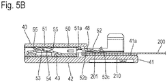
- Fig. 5B shows a state in which the terminal of the FPC 200 is inserted and put in between the plate-shaped part 41 of the housing 40 and the spring piece 52 of the socket terminal 50 located on the plate-shaped part 41 to attach the FPC 200.
- the terminal of the FPC 200 is pinched and mechanically connected by the plate-shaped part 41 and the spring pieces 52 of the socket terminals 50, and also the spring pieces 52 come into contact with the lands 201 arranged on the terminal of the FPC 200 respectively, whereby the thirteen socket terminals 50 are electrically connected to the lands 201 of the FPC 200, respectively.
- the terminal accommodating part 42 of the housing 40 receives force that the spring pieces 52 receive from the FPC 200.
- the cover 60 is attached after the FPC 200 is attached as described above.
- the cover 60 is attached to the housing 40 from the upper side of the housing 40 as shown in Fig. 8A .
- two protruding parts 61 provided on the cover 60 pass through two holes 220 in the reinforcing plate 210 in the terminal of the FPC 200, and inserted into two insertion holes 45 in the plate-shaped part 41 of the housing 40, thereby preventing the FPC 200 from coming off.
- Fig. 8B shows a state in which the FPC 200 has been attached and thus the assembly of the connector 100 is completed as in the case of Fig. 3B .
- the socket terminal 50 include the spring piece 52 located on the plate-shaped part 41 of the housing 40, and the FPC 200 and the connector 100 can be connected to each other by merely inserting and putting the terminal of the FPC 200 in between the spring piece 52 and the plate-shaped part 41. Therefore, the connector 100 can be attached to the FPC 200 extremely simply.
- the spring piece 52 is also provided with the bridges, and as described above, the portions at which the bridges are provided, that is, the spring piece 52 has the horizontal part 52b at which the bridge cut marks 59b and 59c are located.
- the existence of the horizontal part 52b as described above increases the length of the spring piece 52, and weakens the spring force, but this example has a structure for strengthening the spring force. This point will be described below.
- each accommodating hole 43 of the terminal accommodating part 42 of the housing 40 has, at an inner surface thereof, a protrusion 48 that protrudes from the inner surface.
- the protrusion 48 functions, while the spring piece 52 is in contact with the land 201, as a fixed end of the spring piece 52 by locating between the tip (free end) of the spring piece 52 and a rear end 51a of the box part 51 from which the spring piece 52 extends, and receives the force that the spring piece 52 receives from the FPC 200.
- the provision of such a protrusion 48 shortens the effective length of the spring piece 52, which makes it possible to strengthen the spring force.
- the protrusion 48 is in contact with the horizontal part 52b of the spring piece 52 to restrict the movement of the horizontal part 52b, and the horizontal part 52b is used as a substantially fixed end.
- the embodiment of the present invention has been described above.
- the FPC 200 is prevented from coming off by protruding parts 61 of the cover 60, and therefore even when external force such as pulling force is applied to the FPC 200, the contact part between the spring piece 52 and the land 201 is not affected by the external force, and is kept in an excellent contact state.
- the contact part between the spring piece 52 and the land 201 may be subjected to not only spring connection, but also soldering-based connection according to a condition for use. Since the contact part 52c of the spring piece 52 is entirely plated, soldering can be excellently performed. Further, as shown in Fig. 5B , the upper side of the spring piece 52 is opened in a state where the terminal of the FPC 200 is inserted and put in between the plate-shaped part 41 and the spring piece 52, so that a soldering work and an inspection on a soldered state can be easily performed.
- the cover 60 Since the spring pieces 52 and the lands 201 are covered by the cover 60, it is possible to avoid dust or the like from entering the contact parts between the spring pieces 52 and the lands 201 and causing the contact parts to be soiled.
- Fig. 10 shows an aspect in which the connector 100 described above is connected to a counterpart connector 300
- Fig. 11 shows a state in which the connection between the connector 100 and the counterpart connector 300 is completed.
- the cover 60 is provided with a lock arm 62 which is hooked to the counterpart connector 300 to maintain the connection.
Landscapes
- Coupling Device And Connection With Printed Circuit (AREA)
Abstract
Description
- The present invention relates to a connector connectable to a counterpart connector having pin terminals and attachable to a flat cable at an end thereof having lands for electrical contacts.
-
Figs. 1 and2 show aplug connector 10 described inJapanese Registered Patent No. 6664111 Fig. 1 shows an aspect in which theplug connector 10 is attached to a flexible flat cable (FPC) 20, andFig. 2 shows theplug connector 10 attached to the FPC 20, together with areceptacle connector 30 into which theplug connector 10 is to be fitted. - The
plug connector 10 includes a rectangularparallelepiped plug housing 11 andplug terminals 12 housed inside theplug housing 11. Theplug terminals 12 are arranged in a row laterally (in a horizontal direction) in theplug housing 11. - The FPC 20 includes
FPC terminals 23 which are formed by exposingconductor layers 22 in aconnection region 21 to be connected to theplug connector 10.Coupling parts 12a of theplug terminals 12 are located on and soldered to theFPC terminals 23, whereby theplug terminals 12 of theplug connector 10 are connected to theFPC terminals 23 of the FPC 20. - As described above, in the
conventional plug connector 10 to be attached to the FPC 20, theplug terminals 12 of theplug connector 10 and theFPC terminals 23 of the FPC 20 are all connected by soldering. In order to excellently solder thecoupling parts 12a of all theplug terminals 12 to theFPC terminals 23, the coplanarity of thecoupling parts 12a of theplug terminals 12 is a major factor, and in that respect, such a soldering-based connection is not good in workability. - In view of this problem, an object of the present invention is to provide a connector which is attachable to an end of a flat cable and can be easily connected to the flat cable. Here, the flat cable means a deformable sheet-shaped cable such as a flexible printed circuit board (FPC) cable or a flexible flat cable (FFC), and these cables are generically named as "flat cable".
- Technical matters described herein neither intend to explicitly or implicitly limit the invention recited in the claims nor express the possibility of accepting such a limitation by persons other than those who benefit from the present invention (for example, the applicant and proprietors), and are merely described for ease of understanding of the gist of the present invention. The outline of the present invention from another point of view can be understood from, for example, the claims at the time of filing this patent application.
- The connector of the present invention is a connector that is connectable to a counterpart connector having a pin terminal and is attachable to a flat cable at an end thereof having a land for an electrical contact.
- The connector includes a housing and a socket terminal.
- The housing includes a plate-shaped portion and a terminal accommodating portion continuous with the plate-shaped portion. The terminal accommodating portion has an accommodating hole. The accommodating hole penetrates through the terminal accommodating portion and has an end that is open to the plate-shaped portion. The accommodating hole holds the socket terminal inside thereof.
- The socket terminal includes a box portion and a spring portion. The box portion is used for receiving the pin terminal of the counterpart connector. Thus, the box portion will be in direct contact with the pin terminal of the counterpart connector. The spring portion has a cantilever shape and extends from the box portion, through the end of the accommodating hole, onto the plate-shaped portion.
- The spring portion separates, in response to insertion of the end of the flat cable into the connector, from the plate-shaped portion in order to make space for the end of the flat cable, make contact with the land of the flat cable after the insertion of the end of the flat cable, and furthermore make contact with the terminal accommodating portion to transmit to the terminal accommodating portion part of force that the spring portion receives from the end of the flat cable.
- In one aspect, the accommodating hole of the terminal accommodating portion has, at an inner surface thereof, a protrusion protruding from the inner surface. After the insertion of the end of the flat cable, the protrusion serves as a supporter to give the spring portion a support point that is located between, exclusively, a base end of the spring portion and a free end of the spring portion, and receives the part of force that the spring portion receives from the flat cable. The base end of the spring portion serves as a so-called "fixed end" regardless of the insertion of the end of the flat cable. In the connector, the contact between the spring portion and the protrusion, which will be caused by the insertion of the end of the flat cable into the connector, will provide the cantilever -- that is, the spring portionwith the new support point and effect changes in the leverage of the cantilever.
- In another aspect, the spring portion has a bridge cut mark that is located between, exclusively, the base end of the spring portion and a contact portion of the spring portion. The contact portion is used for a contact with the land. The contact portion in whole is plated. The bridge cut mark is an evidence of cutting of a bridge that is used for connecting the socket terminal to another socket terminal in a manufacturing process of the socket terminal. The spring portion has a wider width at the bridge cut mark, and preferably has, at the bridge cut mark, a width wider than that of the rest of the spring portion. Thus, the protrusion of the accommodating hole can reliably and stably make contact with the spring portion at the bridge cut mark thereof.
- According to the connector of the present invention, attachment of the connector to a flat cable and the electrical connection between a socket terminal of the connector and a land of the flat cable can be performed by inserting the flat cable into the connector, so that a work for connecting to the flat cable can be extremely simply performed.
-
-
Fig. 1 is a perspective view showing an aspect in which a conventional connector (plug connector) is attached to an FPC; -
Fig. 2 is a perspective view showing an aspect in which the conventional connector (plug connector) is fitted into a receptacle connector; -
Fig. 3A is a perspective view of an embodiment of a connector according to the present invention when viewing the connector from a front side; -
Fig. 3B is a perspective view of the connector when viewing the connector shown inFig. 3A from a rear side; -
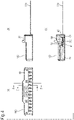
Fig. 4 is a diagram showing the connector shown inFig. 3A , wherein (a) ofFig. 4 is a front view of the connector shown inFig. 3A , (b) ofFig. 4 is a side view of the connector shown inFig. 3A , and (c) ofFig. 4 is a sectional view taken along line D-D of (a) ofFig. 4 ; -
Fig. 5A is an enlarged cross-sectional view taken along line E-E of (a) ofFig. 4 ; -
Fig. 5B is an enlarged cross-sectional view taken when a cover is removed inFig. 5A ; -
Fig. 6 is a perspective view of a socket terminal inFig. 5A ; -
Fig. 7A is a diagram (part 1) showing an assembly of the connector shown inFig. 3A ; -
Fig. 7B is a diagram (part 2) showing the assembly of the connector shown inFig. 3A ; -
Fig. 8A is a diagram (part 3) showing the assembly of the connector shown inFig. 3A ; -
Fig. 8B is a diagram showing an assembly completed state; -
Fig. 9 is a diagram showing the connector, wherein (a) ofFig. 9 is a front view showing a state in which the socket terminal is housed and held in a housing, and (b) ofFig. 9 is a cross-sectional view taken along line C-C of (a) ofFig. 9 ; -
Fig. 10 is a perspective view showing an aspect in which the connector shown inFig. 3A is connected to a counterpart connector; and -
Fig. 11 is a perspective view showing a connection state between the connector shown inFig. 3A and the counterpart connector. -
- 10
- plug connector
- 11
- Plug housing
- 12
- plug terminal
- 12a
- coupling part
- 20
- FPC
- 21
- connection region
- 22
- conductor layer
- 23
- FPC terminal
- 30
- receptacle connector
- 40
- housing
- 41
- plate-shaped part
- 41a
- top surface
- 42
- terminal accommodating part
- 43
- accommodating hole
- 44
- protruding part
- 45
- insertion hole
- 46
- protruding piece
- 46a
- protrusion
- 47
- protrusion
- 48
- protrusion
- 50
- socket terminal
- 51
- box part
- 51a
- rear end
- 51b, 51c
- side wall
- 51d
- upper plate part
- 52
- spring piece
- 52a
- slope part
- 52b
- horizontal part
- 52c
- contact part
- 53, 54
- internal spring piece
- 55
- protruding part
- 56, 57
- window
- 58
- protrusion
- 59a, 59b, 59c
- bridge cut mark
- 60
- cover
- 61
- protruding part
- 62
- lock arm
- 100
- connector
- 200
- FPC
- 201
- land
- 210
- reinforcing plate
- 220
- hole
- 300
- counterpart connector
- An embodiment of the present invention will be described by way of examples with reference to the drawings.
-
Figs. 3A ,3B ,4 and5A show an embodiment of a connector according to the present invention which is attached to a terminal of an FPC (FPC cable). Aconnector 100 comprises ahousing 40,socket terminals 50, and acover 60. In this example, theFPC 200 is configured such that a reinforcingplate 210 is attached to a terminal to be connected to theconnector 100. -
Fig. 6 shows the details of asocket terminal 50, andFigs. 7A ,7B ,8A and8B show an aspect in which assembly of theconnector 100 and attachment of theconnector 100 to the terminal of theFPC 200 are performed in order. - As shown in
Fig. 6 , thesocket terminal 50 comprises abox part 51 having a square tubular outer shape into which a pin terminal of a counterpart connector is to be inserted, and aspring piece 52 having a cantilever shape, thespring piece 52 extending rearward from arear end 51a of thebox part 51. - As shown in
Fig. 5A , a pair ofinternal spring pieces box part 51 so as to be arranged in a front-rear direction of thebox part 51, and so that free ends thereof overlap each other. Theseinternal spring pieces side wall 51b of thebox part 51. - As shown in
Fig. 5A , two protrudingparts 55 protruding to the inner surface side are formed on anupper plate part 51d of thebox part 51, and theinner spring piece 53 whose spring force is reinforced by these protrudingparts 55 and theinternal spring piece 54 serves as a contact part which contacts the pin terminal of the counterpart connector inserted into thebox part 51 while pinching the pin terminal of the counterpart connector. -
Windows 56 for checking the position (height position) of theinternal spring piece 53 are formed on a pair ofside walls box part 51, and twowindows 57 for checking the heights of the two protrudingparts 55 are formed at each of corner portions formed by theside walls upper plate part 51d. Further,protrusions 58 are formed on the pair ofside walls side walls - The
spring piece 52 extends from theupper plate part 51d of thebox part 51, and comprises aslope part 52a which slopes and extends downward from theupper plate part 51d of thebox part 51, ahorizontal part 52b following theslope part 52a, and acontact part 52c following thehorizontal part 52b. Thecontact part 52c has such a shape as to be bent in an L-shape in a direction in which the tip (free end) thereof faces upward. - The
socket terminal 50 having the foregoing shape is formed by pressing a metal plate. InFig. 6 , 59a to 59c indicate bridge cut marks. In this example, thecontact part 52c on the tip end side of thespring piece 52 is gold-plated. - As shown in
Fig. 6 , the bridge cutmark 59a is located at the front end of thebox part 51, and the bridge cut marks 59b and 59c are located on both sides in the width direction of thehorizontal part 52b of thespring piece 52. The reason why the bridges are provided not only on thebox part 51, but also on thespring piece 52 as described above is to stabilize the shape and quality in the press working and the plating processing. Note that theentire contact part 52c can be excellently plated by providing the bridge cut marks 59b and 59c on thehorizontal part 52b in thespring piece 52. - As shown in
Fig. 7A , thehousing 40 includes a plate-shapedpart 41 and aterminal accommodating part 42 following the plate-shapedpart 41. Theterminal accommodating part 42 has a flat rectangular parallelepiped shape. Accommodatingholes 43 are formed through theterminal accommodating part 42 so as to be arranged in a row and so that the rear ends of theaccommodating holes 43 open toward the plate-shapedpart 41. In this example, thirteenaccommodating holes 43 are formed. - The
socket terminal 50 is to be inserted into each of theseaccommodating holes 43. As shown inFig. 7A , thesocket terminal 50 is inserted into theaccommodating hole 43 from a front side of the terminal accommodating part 42 (a side opposite to a side where the plate-shapedpart 41 is located) with thespring piece 52 being placed at the head. -
Fig. 9 shows a state in which thesocket terminals 50 are housed in theaccommodating holes 43 of theterminal accommodating part 42 of thehousing 40. The pair ofprotrusions 58 provided on thebox part 51 of eachsocket terminal 50 are hooked to protruding parts 44 on the inner surface of eachaccommodating hole 43 so as to protrude from the inner surface of theaccommodating hole 43, whereby thesocket terminals 50 are prevented from coming off and are retained in the accommodating holes 43. Note that thespring pieces 52 of thesocket terminals 50 are located so as to protrude onto the plate-shapedpart 41 of thehousing 40. - In this way, the
FPC 200 is attached to thehousing 40 with thesocket terminals 50 being attached to thehousing 40. As shown inFig. 7B , theFPC 200 is to be inserted from the rear side of the plate-shapedpart 41 along theupper surface 41a of the plate-shapedpart 41, and put in between the plate-shapedpart 41 and thespring pieces 52 of thesocket terminals 50. -
Fig. 5B shows a state in which the terminal of theFPC 200 is inserted and put in between the plate-shapedpart 41 of thehousing 40 and thespring piece 52 of thesocket terminal 50 located on the plate-shapedpart 41 to attach theFPC 200. The terminal of theFPC 200 is pinched and mechanically connected by the plate-shapedpart 41 and thespring pieces 52 of thesocket terminals 50, and also thespring pieces 52 come into contact with thelands 201 arranged on the terminal of theFPC 200 respectively, whereby the thirteensocket terminals 50 are electrically connected to thelands 201 of theFPC 200, respectively. Theterminal accommodating part 42 of thehousing 40 receives force that thespring pieces 52 receive from theFPC 200. - The
cover 60 is attached after theFPC 200 is attached as described above. Thecover 60 is attached to thehousing 40 from the upper side of thehousing 40 as shown inFig. 8A . At this time, in this example, two protrudingparts 61 provided on thecover 60 pass through twoholes 220 in the reinforcingplate 210 in the terminal of theFPC 200, and inserted into twoinsertion holes 45 in the plate-shapedpart 41 of thehousing 40, thereby preventing theFPC 200 from coming off. - With respect to the fixing of the
cover 60 to thehousing 40,protrusions 46a formed at the tips of protrudingpieces 46 which are formed at both ends in the width direction of the plate-shapedpart 41 of thehousing 40 so as to protrude from the plate-shapedpart 41, andprotrusions 47 which are formed on both side surfaces in the width direction of theterminal accommodating part 42 are hooked to thecover 60 inside thecover 60, whereby thecover 60 is fixed to thehousing 40.Fig. 8B shows a state in which theFPC 200 has been attached and thus the assembly of theconnector 100 is completed as in the case ofFig. 3B . - According to the
connector 100 described above, thesocket terminal 50 include thespring piece 52 located on the plate-shapedpart 41 of thehousing 40, and theFPC 200 and theconnector 100 can be connected to each other by merely inserting and putting the terminal of theFPC 200 in between thespring piece 52 and the plate-shapedpart 41. Therefore, theconnector 100 can be attached to theFPC 200 extremely simply. - In order to stabilize the shape and quality of the
socket terminals 50 formed by the press working, thespring piece 52 is also provided with the bridges, and as described above, the portions at which the bridges are provided, that is, thespring piece 52 has thehorizontal part 52b at which the bridge cut marks 59b and 59c are located. The existence of thehorizontal part 52b as described above increases the length of thespring piece 52, and weakens the spring force, but this example has a structure for strengthening the spring force. This point will be described below. - As shown in
Figs. 5A and5B , in this example, eachaccommodating hole 43 of theterminal accommodating part 42 of thehousing 40 has, at an inner surface thereof, aprotrusion 48 that protrudes from the inner surface. Theprotrusion 48 functions, while thespring piece 52 is in contact with theland 201, as a fixed end of thespring piece 52 by locating between the tip (free end) of thespring piece 52 and arear end 51a of thebox part 51 from which thespring piece 52 extends, and receives the force that thespring piece 52 receives from theFPC 200. The provision of such aprotrusion 48 shortens the effective length of thespring piece 52, which makes it possible to strengthen the spring force. Note that theprotrusion 48 is in contact with thehorizontal part 52b of thespring piece 52 to restrict the movement of thehorizontal part 52b, and thehorizontal part 52b is used as a substantially fixed end. - The embodiment of the present invention has been described above. The
FPC 200 is prevented from coming off by protrudingparts 61 of thecover 60, and therefore even when external force such as pulling force is applied to theFPC 200, the contact part between thespring piece 52 and theland 201 is not affected by the external force, and is kept in an excellent contact state. - Further, in order to strengthen the connection state between the
spring piece 52 and theland 201 more greatly, the contact part between thespring piece 52 and theland 201 may be subjected to not only spring connection, but also soldering-based connection according to a condition for use. Since thecontact part 52c of thespring piece 52 is entirely plated, soldering can be excellently performed. Further, as shown inFig. 5B , the upper side of thespring piece 52 is opened in a state where the terminal of theFPC 200 is inserted and put in between the plate-shapedpart 41 and thespring piece 52, so that a soldering work and an inspection on a soldered state can be easily performed. - Since the
spring pieces 52 and thelands 201 are covered by thecover 60, it is possible to avoid dust or the like from entering the contact parts between thespring pieces 52 and thelands 201 and causing the contact parts to be soiled. -
Fig. 10 shows an aspect in which theconnector 100 described above is connected to acounterpart connector 300, andFig. 11 shows a state in which the connection between theconnector 100 and thecounterpart connector 300 is completed. Thecover 60 is provided with alock arm 62 which is hooked to thecounterpart connector 300 to maintain the connection.
Claims (5)
- A connector connectable to a counterpart connector having pin terminals and attachable to a flat cable at an end thereof having lands for electrical contacts, the connector comprising:a housing including a plate-shaped portion and a terminal accommodating portion continuous with the plate-shaped portion, the terminal accommodating portion having accommodating holes, each of the accommodating holes penetrating through the terminal accommodating portion and having an end opening to the plate-shaped portion; andsocket terminals respectively held in the accommodating holes, each of the socket terminals including a box portion and a spring portion, the box portion being used for receiving a corresponding one of the pin terminals of the counterpart connector, and the spring portion having a cantilever shape and extending from the box portion, through the end of a corresponding one of the accommodating holes, onto the plate-shaped portion,wherein the spring portion is configured to:in response to insertion of the end of the flat cable, separate from the plate-shaped portion in order to make space for the end of the flat cable;make contact with a corresponding one of the lands of the flat cable after the insertion of the end of the flat cable; andmake contact with the terminal accommodating portion to transmit to the terminal accommodating portion part of force that the spring portion receives from the end of the flat cable.
- The connector according to claim 1, wherein the connector further comprises a cover attachable to the housing of the connector and configured to cover the lands and every spring portion.
- The connector according to claim 2, wherein the flat cable is designed to have a through-hole,the plate-shaped portion has an insertion hole, andthe cover has a protruding portion configured to pass through the through-hole in the flat cable and thus to go into the insertion hole.
- The connector according to any one of claims 1 to 3, wherein each of the accommodating holes of the terminal accommodating portion has, at an inner surface thereof, a protrusion protruding from the inner surface,
after the insertion of the end of the flat cable, the protrusion serves as a supporter to give the spring portion a support point located between a base end of the spring portion and a free end of the spring portion, and receives the part of force that the spring portion receives from the flat cable. - The connector according to any one of claims 1 to 4, wherein the spring portion has a bridge cut mark located between a base end of the spring portion and a contact portion of the spring portion that is used for a contact with the corresponding one of the lands, the bridge cut mark being an evidence of cutting of a bridge used for connecting the socket terminals to each other in a manufacturing process of the socket terminals, and
the contact portion in whole is plated.
Applications Claiming Priority (1)
| Application Number | Priority Date | Filing Date | Title |
|---|---|---|---|
| JP2020207489A JP7472008B2 (en) | 2020-12-15 | 2020-12-15 | connector |
Publications (2)
| Publication Number | Publication Date |
|---|---|
| EP4016747A1 true EP4016747A1 (en) | 2022-06-22 |
| EP4016747B1 EP4016747B1 (en) | 2024-02-28 |
Family
ID=78483168
Family Applications (1)
| Application Number | Title | Priority Date | Filing Date |
|---|---|---|---|
| EP21204617.1A Active EP4016747B1 (en) | 2020-12-15 | 2021-10-26 | Connector |
Country Status (4)
| Country | Link |
|---|---|
| US (1) | US11705653B2 (en) |
| EP (1) | EP4016747B1 (en) |
| JP (1) | JP7472008B2 (en) |
| CN (1) | CN114639976B (en) |
Families Citing this family (8)
| Publication number | Priority date | Publication date | Assignee | Title |
|---|---|---|---|---|
| JP2020068168A (en) * | 2018-10-26 | 2020-04-30 | 株式会社オートネットワーク技術研究所 | connector |
| JP7125653B2 (en) * | 2018-10-30 | 2022-08-25 | 株式会社オートネットワーク技術研究所 | connector |
| CN115135002A (en) * | 2021-03-25 | 2022-09-30 | 华为技术有限公司 | Business board and communication equipment |
| JP7533358B2 (en) * | 2021-05-26 | 2024-08-14 | 株式会社オートネットワーク技術研究所 | Flexible Cable Connectors |
| USD986186S1 (en) * | 2021-06-03 | 2023-05-16 | Jess-Link Products Co., Ltd. | Electrical connector |
| JP1703927S (en) * | 2021-06-23 | 2022-01-04 | ||
| JP2025007633A (en) * | 2023-07-03 | 2025-01-17 | メクテック株式会社 | Junction box |
| JP1790020S (en) * | 2024-08-02 | 2025-01-28 | Connector Housing |
Citations (7)
| Publication number | Priority date | Publication date | Assignee | Title |
|---|---|---|---|---|
| JPH0364111B2 (en) | 1986-09-30 | 1991-10-03 | Kogyo Gijutsuin | |
| WO1998033246A1 (en) * | 1997-01-29 | 1998-07-30 | Ut Automotive Dearborn, Inc. | Method for connecting flat flexible cable and a connector |
| US5967833A (en) * | 1996-08-20 | 1999-10-19 | North American Specialties Corporation | Circuit connector with multiple contacts and built in strain relief |
| JP2007141784A (en) * | 2005-11-22 | 2007-06-07 | Auto Network Gijutsu Kenkyusho:Kk | Connector terminals and connectors for flat wiring materials |
| US20100190373A1 (en) * | 2008-01-22 | 2010-07-29 | Shih-Kun Yeh | Flat cable connector |
| DE202012005124U1 (en) * | 2012-05-24 | 2012-06-06 | Briloner Leuchten Gmbh | Device for contacting an LED strip and device for the electrically conductive connection of at least two LED strips |
| US20170324178A1 (en) * | 2016-05-06 | 2017-11-09 | Alltop Electronics (Suzhou) Ltd. | Connector for flexible printed circuit board |
Family Cites Families (8)
| Publication number | Priority date | Publication date | Assignee | Title |
|---|---|---|---|---|
| JP3396193B2 (en) | 1999-11-10 | 2003-04-14 | 日本圧着端子製造株式会社 | Socket connector |
| US6551121B1 (en) * | 2001-12-27 | 2003-04-22 | Hon Hai Precision Ind. Co., Ltd. | Card edge connector having compact structure |
| DE10262045B4 (en) * | 2002-10-31 | 2005-06-02 | Fci | Connector for flex ribbon cable |
| JP4931417B2 (en) * | 2005-12-27 | 2012-05-16 | モレックス インコーポレイテド | Connector for cable connection |
| JP5029965B2 (en) * | 2007-06-29 | 2012-09-19 | 山一電機株式会社 | Adapter for cable connector |
| JP5890157B2 (en) * | 2011-11-25 | 2016-03-22 | 日本航空電子工業株式会社 | Wire-to-board connector |
| JP6664111B2 (en) | 2014-12-05 | 2020-03-13 | パナソニックIpマネジメント株式会社 | Plug connector and connector set |
| JP2019102220A (en) | 2017-11-30 | 2019-06-24 | 第一精工株式会社 | Connector and manufacturing method of connector |
-
2020
- 2020-12-15 JP JP2020207489A patent/JP7472008B2/en active Active
-
2021
- 2021-10-26 EP EP21204617.1A patent/EP4016747B1/en active Active
- 2021-10-29 US US17/514,570 patent/US11705653B2/en active Active
- 2021-11-08 CN CN202111313560.9A patent/CN114639976B/en active Active
Patent Citations (7)
| Publication number | Priority date | Publication date | Assignee | Title |
|---|---|---|---|---|
| JPH0364111B2 (en) | 1986-09-30 | 1991-10-03 | Kogyo Gijutsuin | |
| US5967833A (en) * | 1996-08-20 | 1999-10-19 | North American Specialties Corporation | Circuit connector with multiple contacts and built in strain relief |
| WO1998033246A1 (en) * | 1997-01-29 | 1998-07-30 | Ut Automotive Dearborn, Inc. | Method for connecting flat flexible cable and a connector |
| JP2007141784A (en) * | 2005-11-22 | 2007-06-07 | Auto Network Gijutsu Kenkyusho:Kk | Connector terminals and connectors for flat wiring materials |
| US20100190373A1 (en) * | 2008-01-22 | 2010-07-29 | Shih-Kun Yeh | Flat cable connector |
| DE202012005124U1 (en) * | 2012-05-24 | 2012-06-06 | Briloner Leuchten Gmbh | Device for contacting an LED strip and device for the electrically conductive connection of at least two LED strips |
| US20170324178A1 (en) * | 2016-05-06 | 2017-11-09 | Alltop Electronics (Suzhou) Ltd. | Connector for flexible printed circuit board |
Also Published As
| Publication number | Publication date |
|---|---|
| JP7472008B2 (en) | 2024-04-22 |
| JP2022094541A (en) | 2022-06-27 |
| EP4016747B1 (en) | 2024-02-28 |
| US11705653B2 (en) | 2023-07-18 |
| US20220190501A1 (en) | 2022-06-16 |
| CN114639976A (en) | 2022-06-17 |
| CN114639976B (en) | 2025-04-04 |
Similar Documents
| Publication | Publication Date | Title |
|---|---|---|
| US11705653B2 (en) | Connector attachable to a flat cable and connectable to a counterpart connector | |
| JP7774608B2 (en) | Connector and connector assembly | |
| JP4827971B2 (en) | Flexible wiring board fixing structure | |
| EP2600469A2 (en) | Circuit-terminal connecting device | |
| US7806702B2 (en) | Connector for an electric device such as a board | |
| JP2020181639A (en) | connector | |
| CN108780966B (en) | Waterproof connector for substrate | |
| EP3316406B1 (en) | Electronic device and connector | |
| CN101118993A (en) | Thin connector | |
| US8388379B2 (en) | Shield case, connector having the shield case, and electronic equipment having the connector | |
| EP1993172A1 (en) | Fixer, surface-mount component using the fixer, and mounting structure using the fixer | |
| JP4391975B2 (en) | Electrical connector | |
| US9455537B2 (en) | Electrical connector lock | |
| JP4563915B2 (en) | Circuit board electrical connector | |
| US7104824B2 (en) | Connectors for connecting mating connectors to connection objects | |
| JP5240528B2 (en) | Modular jack | |
| KR100559308B1 (en) | Electrical connector for connecting a mating contact and a connection object | |
| CN102576959B (en) | Wire-to-board connector | |
| CN104412459A (en) | Flexible multi-wire connector | |
| CN112242637B (en) | Modular Plugs and Cable Harnesses | |
| CN120357229A (en) | Electric connector and connector device | |
| JP5367120B2 (en) | connector | |
| JP2019053839A (en) | Electrical connector |
Legal Events
| Date | Code | Title | Description |
|---|---|---|---|
| PUAI | Public reference made under article 153(3) epc to a published international application that has entered the european phase |
Free format text: ORIGINAL CODE: 0009012 |
|
| STAA | Information on the status of an ep patent application or granted ep patent |
Free format text: STATUS: THE APPLICATION HAS BEEN PUBLISHED |
|
| AK | Designated contracting states |
Kind code of ref document: A1 Designated state(s): AL AT BE BG CH CY CZ DE DK EE ES FI FR GB GR HR HU IE IS IT LI LT LU LV MC MK MT NL NO PL PT RO RS SE SI SK SM TR |
|
| STAA | Information on the status of an ep patent application or granted ep patent |
Free format text: STATUS: REQUEST FOR EXAMINATION WAS MADE |
|
| 17P | Request for examination filed |
Effective date: 20221222 |
|
| RBV | Designated contracting states (corrected) |
Designated state(s): AL AT BE BG CH CY CZ DE DK EE ES FI FR GB GR HR HU IE IS IT LI LT LU LV MC MK MT NL NO PL PT RO RS SE SI SK SM TR |
|
| STAA | Information on the status of an ep patent application or granted ep patent |
Free format text: STATUS: EXAMINATION IS IN PROGRESS |
|
| 17Q | First examination report despatched |
Effective date: 20230221 |
|
| GRAP | Despatch of communication of intention to grant a patent |
Free format text: ORIGINAL CODE: EPIDOSNIGR1 |
|
| STAA | Information on the status of an ep patent application or granted ep patent |
Free format text: STATUS: GRANT OF PATENT IS INTENDED |
|
| GRAJ | Information related to disapproval of communication of intention to grant by the applicant or resumption of examination proceedings by the epo deleted |
Free format text: ORIGINAL CODE: EPIDOSDIGR1 |
|
| GRAP | Despatch of communication of intention to grant a patent |
Free format text: ORIGINAL CODE: EPIDOSNIGR1 |
|
| INTG | Intention to grant announced |
Effective date: 20230919 |
|
| INTG | Intention to grant announced |
Effective date: 20231006 |
|
| GRAS | Grant fee paid |
Free format text: ORIGINAL CODE: EPIDOSNIGR3 |
|
| GRAA | (expected) grant |
Free format text: ORIGINAL CODE: 0009210 |
|
| STAA | Information on the status of an ep patent application or granted ep patent |
Free format text: STATUS: THE PATENT HAS BEEN GRANTED |
|
| AK | Designated contracting states |
Kind code of ref document: B1 Designated state(s): AL AT BE BG CH CY CZ DE DK EE ES FI FR GB GR HR HU IE IS IT LI LT LU LV MC MK MT NL NO PL PT RO RS SE SI SK SM TR |
|
| REG | Reference to a national code |
Ref country code: GB Ref legal event code: FG4D |
|
| REG | Reference to a national code |
Ref country code: CH Ref legal event code: EP |
|
| REG | Reference to a national code |
Ref country code: DE Ref legal event code: R096 Ref document number: 602021009799 Country of ref document: DE |
|
| REG | Reference to a national code |
Ref country code: IE Ref legal event code: FG4D |
|
| REG | Reference to a national code |
Ref country code: LT Ref legal event code: MG9D |
|
| PG25 | Lapsed in a contracting state [announced via postgrant information from national office to epo] |
Ref country code: IS Free format text: LAPSE BECAUSE OF FAILURE TO SUBMIT A TRANSLATION OF THE DESCRIPTION OR TO PAY THE FEE WITHIN THE PRESCRIBED TIME-LIMIT Effective date: 20240628 |
|
| REG | Reference to a national code |
Ref country code: NL Ref legal event code: MP Effective date: 20240228 |
|
| PG25 | Lapsed in a contracting state [announced via postgrant information from national office to epo] |
Ref country code: LT Free format text: LAPSE BECAUSE OF FAILURE TO SUBMIT A TRANSLATION OF THE DESCRIPTION OR TO PAY THE FEE WITHIN THE PRESCRIBED TIME-LIMIT Effective date: 20240228 |
|
| PG25 | Lapsed in a contracting state [announced via postgrant information from national office to epo] |
Ref country code: GR Free format text: LAPSE BECAUSE OF FAILURE TO SUBMIT A TRANSLATION OF THE DESCRIPTION OR TO PAY THE FEE WITHIN THE PRESCRIBED TIME-LIMIT Effective date: 20240529 |
|
| PG25 | Lapsed in a contracting state [announced via postgrant information from national office to epo] |
Ref country code: HR Free format text: LAPSE BECAUSE OF FAILURE TO SUBMIT A TRANSLATION OF THE DESCRIPTION OR TO PAY THE FEE WITHIN THE PRESCRIBED TIME-LIMIT Effective date: 20240228 Ref country code: NL Free format text: LAPSE BECAUSE OF FAILURE TO SUBMIT A TRANSLATION OF THE DESCRIPTION OR TO PAY THE FEE WITHIN THE PRESCRIBED TIME-LIMIT Effective date: 20240228 Ref country code: RS Free format text: LAPSE BECAUSE OF FAILURE TO SUBMIT A TRANSLATION OF THE DESCRIPTION OR TO PAY THE FEE WITHIN THE PRESCRIBED TIME-LIMIT Effective date: 20240528 |
|
| PG25 | Lapsed in a contracting state [announced via postgrant information from national office to epo] |
Ref country code: ES Free format text: LAPSE BECAUSE OF FAILURE TO SUBMIT A TRANSLATION OF THE DESCRIPTION OR TO PAY THE FEE WITHIN THE PRESCRIBED TIME-LIMIT Effective date: 20240228 |
|
| PG25 | Lapsed in a contracting state [announced via postgrant information from national office to epo] |
Ref country code: RS Free format text: LAPSE BECAUSE OF FAILURE TO SUBMIT A TRANSLATION OF THE DESCRIPTION OR TO PAY THE FEE WITHIN THE PRESCRIBED TIME-LIMIT Effective date: 20240528 Ref country code: NO Free format text: LAPSE BECAUSE OF FAILURE TO SUBMIT A TRANSLATION OF THE DESCRIPTION OR TO PAY THE FEE WITHIN THE PRESCRIBED TIME-LIMIT Effective date: 20240528 Ref country code: NL Free format text: LAPSE BECAUSE OF FAILURE TO SUBMIT A TRANSLATION OF THE DESCRIPTION OR TO PAY THE FEE WITHIN THE PRESCRIBED TIME-LIMIT Effective date: 20240228 Ref country code: LT Free format text: LAPSE BECAUSE OF FAILURE TO SUBMIT A TRANSLATION OF THE DESCRIPTION OR TO PAY THE FEE WITHIN THE PRESCRIBED TIME-LIMIT Effective date: 20240228 Ref country code: IS Free format text: LAPSE BECAUSE OF FAILURE TO SUBMIT A TRANSLATION OF THE DESCRIPTION OR TO PAY THE FEE WITHIN THE PRESCRIBED TIME-LIMIT Effective date: 20240628 Ref country code: HR Free format text: LAPSE BECAUSE OF FAILURE TO SUBMIT A TRANSLATION OF THE DESCRIPTION OR TO PAY THE FEE WITHIN THE PRESCRIBED TIME-LIMIT Effective date: 20240228 Ref country code: GR Free format text: LAPSE BECAUSE OF FAILURE TO SUBMIT A TRANSLATION OF THE DESCRIPTION OR TO PAY THE FEE WITHIN THE PRESCRIBED TIME-LIMIT Effective date: 20240529 Ref country code: FI Free format text: LAPSE BECAUSE OF FAILURE TO SUBMIT A TRANSLATION OF THE DESCRIPTION OR TO PAY THE FEE WITHIN THE PRESCRIBED TIME-LIMIT Effective date: 20240228 Ref country code: ES Free format text: LAPSE BECAUSE OF FAILURE TO SUBMIT A TRANSLATION OF THE DESCRIPTION OR TO PAY THE FEE WITHIN THE PRESCRIBED TIME-LIMIT Effective date: 20240228 Ref country code: BG Free format text: LAPSE BECAUSE OF FAILURE TO SUBMIT A TRANSLATION OF THE DESCRIPTION OR TO PAY THE FEE WITHIN THE PRESCRIBED TIME-LIMIT Effective date: 20240228 |
|
| PG25 | Lapsed in a contracting state [announced via postgrant information from national office to epo] |
Ref country code: PL Free format text: LAPSE BECAUSE OF FAILURE TO SUBMIT A TRANSLATION OF THE DESCRIPTION OR TO PAY THE FEE WITHIN THE PRESCRIBED TIME-LIMIT Effective date: 20240228 Ref country code: PT Free format text: LAPSE BECAUSE OF FAILURE TO SUBMIT A TRANSLATION OF THE DESCRIPTION OR TO PAY THE FEE WITHIN THE PRESCRIBED TIME-LIMIT Effective date: 20240628 |
|
| REG | Reference to a national code |
Ref country code: AT Ref legal event code: MK05 Ref document number: 1662117 Country of ref document: AT Kind code of ref document: T Effective date: 20240228 |
|
| PG25 | Lapsed in a contracting state [announced via postgrant information from national office to epo] |
Ref country code: SE Free format text: LAPSE BECAUSE OF FAILURE TO SUBMIT A TRANSLATION OF THE DESCRIPTION OR TO PAY THE FEE WITHIN THE PRESCRIBED TIME-LIMIT Effective date: 20240228 Ref country code: PT Free format text: LAPSE BECAUSE OF FAILURE TO SUBMIT A TRANSLATION OF THE DESCRIPTION OR TO PAY THE FEE WITHIN THE PRESCRIBED TIME-LIMIT Effective date: 20240628 Ref country code: PL Free format text: LAPSE BECAUSE OF FAILURE TO SUBMIT A TRANSLATION OF THE DESCRIPTION OR TO PAY THE FEE WITHIN THE PRESCRIBED TIME-LIMIT Effective date: 20240228 Ref country code: LV Free format text: LAPSE BECAUSE OF FAILURE TO SUBMIT A TRANSLATION OF THE DESCRIPTION OR TO PAY THE FEE WITHIN THE PRESCRIBED TIME-LIMIT Effective date: 20240228 |
|
| PG25 | Lapsed in a contracting state [announced via postgrant information from national office to epo] |
Ref country code: DK Free format text: LAPSE BECAUSE OF FAILURE TO SUBMIT A TRANSLATION OF THE DESCRIPTION OR TO PAY THE FEE WITHIN THE PRESCRIBED TIME-LIMIT Effective date: 20240228 |
|
| PG25 | Lapsed in a contracting state [announced via postgrant information from national office to epo] |
Ref country code: SM Free format text: LAPSE BECAUSE OF FAILURE TO SUBMIT A TRANSLATION OF THE DESCRIPTION OR TO PAY THE FEE WITHIN THE PRESCRIBED TIME-LIMIT Effective date: 20240228 |
|
| PG25 | Lapsed in a contracting state [announced via postgrant information from national office to epo] |
Ref country code: EE Free format text: LAPSE BECAUSE OF FAILURE TO SUBMIT A TRANSLATION OF THE DESCRIPTION OR TO PAY THE FEE WITHIN THE PRESCRIBED TIME-LIMIT Effective date: 20240228 Ref country code: CZ Free format text: LAPSE BECAUSE OF FAILURE TO SUBMIT A TRANSLATION OF THE DESCRIPTION OR TO PAY THE FEE WITHIN THE PRESCRIBED TIME-LIMIT Effective date: 20240228 |
|
| PG25 | Lapsed in a contracting state [announced via postgrant information from national office to epo] |
Ref country code: AT Free format text: LAPSE BECAUSE OF FAILURE TO SUBMIT A TRANSLATION OF THE DESCRIPTION OR TO PAY THE FEE WITHIN THE PRESCRIBED TIME-LIMIT Effective date: 20240228 |
|
| PG25 | Lapsed in a contracting state [announced via postgrant information from national office to epo] |
Ref country code: SK Free format text: LAPSE BECAUSE OF FAILURE TO SUBMIT A TRANSLATION OF THE DESCRIPTION OR TO PAY THE FEE WITHIN THE PRESCRIBED TIME-LIMIT Effective date: 20240228 |
|
| PG25 | Lapsed in a contracting state [announced via postgrant information from national office to epo] |
Ref country code: SM Free format text: LAPSE BECAUSE OF FAILURE TO SUBMIT A TRANSLATION OF THE DESCRIPTION OR TO PAY THE FEE WITHIN THE PRESCRIBED TIME-LIMIT Effective date: 20240228 Ref country code: SK Free format text: LAPSE BECAUSE OF FAILURE TO SUBMIT A TRANSLATION OF THE DESCRIPTION OR TO PAY THE FEE WITHIN THE PRESCRIBED TIME-LIMIT Effective date: 20240228 Ref country code: RO Free format text: LAPSE BECAUSE OF FAILURE TO SUBMIT A TRANSLATION OF THE DESCRIPTION OR TO PAY THE FEE WITHIN THE PRESCRIBED TIME-LIMIT Effective date: 20240228 Ref country code: EE Free format text: LAPSE BECAUSE OF FAILURE TO SUBMIT A TRANSLATION OF THE DESCRIPTION OR TO PAY THE FEE WITHIN THE PRESCRIBED TIME-LIMIT Effective date: 20240228 Ref country code: DK Free format text: LAPSE BECAUSE OF FAILURE TO SUBMIT A TRANSLATION OF THE DESCRIPTION OR TO PAY THE FEE WITHIN THE PRESCRIBED TIME-LIMIT Effective date: 20240228 Ref country code: CZ Free format text: LAPSE BECAUSE OF FAILURE TO SUBMIT A TRANSLATION OF THE DESCRIPTION OR TO PAY THE FEE WITHIN THE PRESCRIBED TIME-LIMIT Effective date: 20240228 Ref country code: AT Free format text: LAPSE BECAUSE OF FAILURE TO SUBMIT A TRANSLATION OF THE DESCRIPTION OR TO PAY THE FEE WITHIN THE PRESCRIBED TIME-LIMIT Effective date: 20240228 |
|
| REG | Reference to a national code |
Ref country code: DE Ref legal event code: R097 Ref document number: 602021009799 Country of ref document: DE |
|
| PG25 | Lapsed in a contracting state [announced via postgrant information from national office to epo] |
Ref country code: IT Free format text: LAPSE BECAUSE OF FAILURE TO SUBMIT A TRANSLATION OF THE DESCRIPTION OR TO PAY THE FEE WITHIN THE PRESCRIBED TIME-LIMIT Effective date: 20240228 |
|
| PG25 | Lapsed in a contracting state [announced via postgrant information from national office to epo] |
Ref country code: IT Free format text: LAPSE BECAUSE OF FAILURE TO SUBMIT A TRANSLATION OF THE DESCRIPTION OR TO PAY THE FEE WITHIN THE PRESCRIBED TIME-LIMIT Effective date: 20240228 |
|
| PLBE | No opposition filed within time limit |
Free format text: ORIGINAL CODE: 0009261 |
|
| STAA | Information on the status of an ep patent application or granted ep patent |
Free format text: STATUS: NO OPPOSITION FILED WITHIN TIME LIMIT |
|
| 26N | No opposition filed |
Effective date: 20241129 |
|
| PG25 | Lapsed in a contracting state [announced via postgrant information from national office to epo] |
Ref country code: SI Free format text: LAPSE BECAUSE OF FAILURE TO SUBMIT A TRANSLATION OF THE DESCRIPTION OR TO PAY THE FEE WITHIN THE PRESCRIBED TIME-LIMIT Effective date: 20240228 |
|
| REG | Reference to a national code |
Ref country code: CH Ref legal event code: PL |
|
| PG25 | Lapsed in a contracting state [announced via postgrant information from national office to epo] |
Ref country code: MC Free format text: LAPSE BECAUSE OF FAILURE TO SUBMIT A TRANSLATION OF THE DESCRIPTION OR TO PAY THE FEE WITHIN THE PRESCRIBED TIME-LIMIT Effective date: 20240228 |
|
| PG25 | Lapsed in a contracting state [announced via postgrant information from national office to epo] |
Ref country code: LU Free format text: LAPSE BECAUSE OF NON-PAYMENT OF DUE FEES Effective date: 20241026 Ref country code: BE Free format text: LAPSE BECAUSE OF NON-PAYMENT OF DUE FEES Effective date: 20241031 |
|
| PG25 | Lapsed in a contracting state [announced via postgrant information from national office to epo] |
Ref country code: CH Free format text: LAPSE BECAUSE OF NON-PAYMENT OF DUE FEES Effective date: 20241031 |
|
| REG | Reference to a national code |
Ref country code: BE Ref legal event code: MM Effective date: 20241031 |
|
| PGFP | Annual fee paid to national office [announced via postgrant information from national office to epo] |
Ref country code: FR Payment date: 20250908 Year of fee payment: 5 |
|
| PG25 | Lapsed in a contracting state [announced via postgrant information from national office to epo] |
Ref country code: IE Free format text: LAPSE BECAUSE OF NON-PAYMENT OF DUE FEES Effective date: 20241026 |
|
| PGFP | Annual fee paid to national office [announced via postgrant information from national office to epo] |
Ref country code: DE Payment date: 20250902 Year of fee payment: 5 |
|
| PG25 | Lapsed in a contracting state [announced via postgrant information from national office to epo] |
Ref country code: CY Free format text: LAPSE BECAUSE OF FAILURE TO SUBMIT A TRANSLATION OF THE DESCRIPTION OR TO PAY THE FEE WITHIN THE PRESCRIBED TIME-LIMIT; INVALID AB INITIO Effective date: 20211026 |
|
| PG25 | Lapsed in a contracting state [announced via postgrant information from national office to epo] |
Ref country code: HU Free format text: LAPSE BECAUSE OF FAILURE TO SUBMIT A TRANSLATION OF THE DESCRIPTION OR TO PAY THE FEE WITHIN THE PRESCRIBED TIME-LIMIT; INVALID AB INITIO Effective date: 20211026 |
|
| PG25 | Lapsed in a contracting state [announced via postgrant information from national office to epo] |
Ref country code: TR Free format text: LAPSE BECAUSE OF FAILURE TO SUBMIT A TRANSLATION OF THE DESCRIPTION OR TO PAY THE FEE WITHIN THE PRESCRIBED TIME-LIMIT Effective date: 20240228 |
|
| GBPC | Gb: european patent ceased through non-payment of renewal fee |
Effective date: 20251026 |
|
| PG25 | Lapsed in a contracting state [announced via postgrant information from national office to epo] |
Ref country code: GB Free format text: LAPSE BECAUSE OF NON-PAYMENT OF DUE FEES Effective date: 20251026 |