EP4016709A1 - Battery pack - Google Patents
Battery pack Download PDFInfo
- Publication number
- EP4016709A1 EP4016709A1 EP20872405.4A EP20872405A EP4016709A1 EP 4016709 A1 EP4016709 A1 EP 4016709A1 EP 20872405 A EP20872405 A EP 20872405A EP 4016709 A1 EP4016709 A1 EP 4016709A1
- Authority
- EP
- European Patent Office
- Prior art keywords
- terminal
- partition wall
- disposed
- control board
- battery pack
- Prior art date
- Legal status (The legal status is an assumption and is not a legal conclusion. Google has not performed a legal analysis and makes no representation as to the accuracy of the status listed.)
- Pending
Links
Images












Classifications
-
- H—ELECTRICITY
- H01—ELECTRIC ELEMENTS
- H01M—PROCESSES OR MEANS, e.g. BATTERIES, FOR THE DIRECT CONVERSION OF CHEMICAL ENERGY INTO ELECTRICAL ENERGY
- H01M50/00—Constructional details or processes of manufacture of the non-active parts of electrochemical cells other than fuel cells, e.g. hybrid cells
- H01M50/20—Mountings; Secondary casings or frames; Racks, modules or packs; Suspension devices; Shock absorbers; Transport or carrying devices; Holders
- H01M50/296—Mountings; Secondary casings or frames; Racks, modules or packs; Suspension devices; Shock absorbers; Transport or carrying devices; Holders characterised by terminals of battery packs
-
- H—ELECTRICITY
- H01—ELECTRIC ELEMENTS
- H01M—PROCESSES OR MEANS, e.g. BATTERIES, FOR THE DIRECT CONVERSION OF CHEMICAL ENERGY INTO ELECTRICAL ENERGY
- H01M10/00—Secondary cells; Manufacture thereof
- H01M10/42—Methods or arrangements for servicing or maintenance of secondary cells or secondary half-cells
- H01M10/425—Structural combination with electronic components, e.g. electronic circuits integrated to the outside of the casing
-
- H—ELECTRICITY
- H01—ELECTRIC ELEMENTS
- H01M—PROCESSES OR MEANS, e.g. BATTERIES, FOR THE DIRECT CONVERSION OF CHEMICAL ENERGY INTO ELECTRICAL ENERGY
- H01M50/00—Constructional details or processes of manufacture of the non-active parts of electrochemical cells other than fuel cells, e.g. hybrid cells
- H01M50/20—Mountings; Secondary casings or frames; Racks, modules or packs; Suspension devices; Shock absorbers; Transport or carrying devices; Holders
- H01M50/204—Racks, modules or packs for multiple batteries or multiple cells
-
- H—ELECTRICITY
- H01—ELECTRIC ELEMENTS
- H01M—PROCESSES OR MEANS, e.g. BATTERIES, FOR THE DIRECT CONVERSION OF CHEMICAL ENERGY INTO ELECTRICAL ENERGY
- H01M50/00—Constructional details or processes of manufacture of the non-active parts of electrochemical cells other than fuel cells, e.g. hybrid cells
- H01M50/20—Mountings; Secondary casings or frames; Racks, modules or packs; Suspension devices; Shock absorbers; Transport or carrying devices; Holders
- H01M50/204—Racks, modules or packs for multiple batteries or multiple cells
- H01M50/207—Racks, modules or packs for multiple batteries or multiple cells characterised by their shape
- H01M50/213—Racks, modules or packs for multiple batteries or multiple cells characterised by their shape adapted for cells having curved cross-section, e.g. round or elliptic
-
- H—ELECTRICITY
- H01—ELECTRIC ELEMENTS
- H01M—PROCESSES OR MEANS, e.g. BATTERIES, FOR THE DIRECT CONVERSION OF CHEMICAL ENERGY INTO ELECTRICAL ENERGY
- H01M50/00—Constructional details or processes of manufacture of the non-active parts of electrochemical cells other than fuel cells, e.g. hybrid cells
- H01M50/20—Mountings; Secondary casings or frames; Racks, modules or packs; Suspension devices; Shock absorbers; Transport or carrying devices; Holders
- H01M50/233—Mountings; Secondary casings or frames; Racks, modules or packs; Suspension devices; Shock absorbers; Transport or carrying devices; Holders characterised by physical properties of casings or racks, e.g. dimensions
- H01M50/24—Mountings; Secondary casings or frames; Racks, modules or packs; Suspension devices; Shock absorbers; Transport or carrying devices; Holders characterised by physical properties of casings or racks, e.g. dimensions adapted for protecting batteries from their environment, e.g. from corrosion
-
- H—ELECTRICITY
- H01—ELECTRIC ELEMENTS
- H01M—PROCESSES OR MEANS, e.g. BATTERIES, FOR THE DIRECT CONVERSION OF CHEMICAL ENERGY INTO ELECTRICAL ENERGY
- H01M50/00—Constructional details or processes of manufacture of the non-active parts of electrochemical cells other than fuel cells, e.g. hybrid cells
- H01M50/20—Mountings; Secondary casings or frames; Racks, modules or packs; Suspension devices; Shock absorbers; Transport or carrying devices; Holders
- H01M50/244—Secondary casings; Racks; Suspension devices; Carrying devices; Holders characterised by their mounting method
-
- H—ELECTRICITY
- H01—ELECTRIC ELEMENTS
- H01M—PROCESSES OR MEANS, e.g. BATTERIES, FOR THE DIRECT CONVERSION OF CHEMICAL ENERGY INTO ELECTRICAL ENERGY
- H01M50/00—Constructional details or processes of manufacture of the non-active parts of electrochemical cells other than fuel cells, e.g. hybrid cells
- H01M50/20—Mountings; Secondary casings or frames; Racks, modules or packs; Suspension devices; Shock absorbers; Transport or carrying devices; Holders
- H01M50/247—Mountings; Secondary casings or frames; Racks, modules or packs; Suspension devices; Shock absorbers; Transport or carrying devices; Holders specially adapted for portable devices, e.g. mobile phones, computers, hand tools or pacemakers
-
- H—ELECTRICITY
- H01—ELECTRIC ELEMENTS
- H01M—PROCESSES OR MEANS, e.g. BATTERIES, FOR THE DIRECT CONVERSION OF CHEMICAL ENERGY INTO ELECTRICAL ENERGY
- H01M50/00—Constructional details or processes of manufacture of the non-active parts of electrochemical cells other than fuel cells, e.g. hybrid cells
- H01M50/20—Mountings; Secondary casings or frames; Racks, modules or packs; Suspension devices; Shock absorbers; Transport or carrying devices; Holders
- H01M50/258—Modular batteries; Casings provided with means for assembling
-
- H—ELECTRICITY
- H01—ELECTRIC ELEMENTS
- H01M—PROCESSES OR MEANS, e.g. BATTERIES, FOR THE DIRECT CONVERSION OF CHEMICAL ENERGY INTO ELECTRICAL ENERGY
- H01M50/00—Constructional details or processes of manufacture of the non-active parts of electrochemical cells other than fuel cells, e.g. hybrid cells
- H01M50/20—Mountings; Secondary casings or frames; Racks, modules or packs; Suspension devices; Shock absorbers; Transport or carrying devices; Holders
- H01M50/284—Mountings; Secondary casings or frames; Racks, modules or packs; Suspension devices; Shock absorbers; Transport or carrying devices; Holders with incorporated circuit boards, e.g. printed circuit boards [PCB]
-
- H—ELECTRICITY
- H01—ELECTRIC ELEMENTS
- H01M—PROCESSES OR MEANS, e.g. BATTERIES, FOR THE DIRECT CONVERSION OF CHEMICAL ENERGY INTO ELECTRICAL ENERGY
- H01M50/00—Constructional details or processes of manufacture of the non-active parts of electrochemical cells other than fuel cells, e.g. hybrid cells
- H01M50/50—Current conducting connections for cells or batteries
- H01M50/502—Interconnectors for connecting terminals of adjacent batteries; Interconnectors for connecting cells outside a battery casing
- H01M50/519—Interconnectors for connecting terminals of adjacent batteries; Interconnectors for connecting cells outside a battery casing comprising printed circuit boards [PCB]
-
- H—ELECTRICITY
- H01—ELECTRIC ELEMENTS
- H01M—PROCESSES OR MEANS, e.g. BATTERIES, FOR THE DIRECT CONVERSION OF CHEMICAL ENERGY INTO ELECTRICAL ENERGY
- H01M50/00—Constructional details or processes of manufacture of the non-active parts of electrochemical cells other than fuel cells, e.g. hybrid cells
- H01M50/50—Current conducting connections for cells or batteries
- H01M50/572—Means for preventing undesired use or discharge
- H01M50/584—Means for preventing undesired use or discharge for preventing incorrect connections inside or outside the batteries
- H01M50/588—Means for preventing undesired use or discharge for preventing incorrect connections inside or outside the batteries outside the batteries, e.g. incorrect connections of terminals or busbars
-
- H—ELECTRICITY
- H01—ELECTRIC ELEMENTS
- H01M—PROCESSES OR MEANS, e.g. BATTERIES, FOR THE DIRECT CONVERSION OF CHEMICAL ENERGY INTO ELECTRICAL ENERGY
- H01M50/00—Constructional details or processes of manufacture of the non-active parts of electrochemical cells other than fuel cells, e.g. hybrid cells
- H01M50/50—Current conducting connections for cells or batteries
- H01M50/572—Means for preventing undesired use or discharge
- H01M50/584—Means for preventing undesired use or discharge for preventing incorrect connections inside or outside the batteries
- H01M50/59—Means for preventing undesired use or discharge for preventing incorrect connections inside or outside the batteries characterised by the protection means
- H01M50/593—Spacers; Insulating plates
-
- B—PERFORMING OPERATIONS; TRANSPORTING
- B25—HAND TOOLS; PORTABLE POWER-DRIVEN TOOLS; MANIPULATORS
- B25F—COMBINATION OR MULTI-PURPOSE TOOLS NOT OTHERWISE PROVIDED FOR; DETAILS OR COMPONENTS OF PORTABLE POWER-DRIVEN TOOLS NOT PARTICULARLY RELATED TO THE OPERATIONS PERFORMED AND NOT OTHERWISE PROVIDED FOR
- B25F5/00—Details or components of portable power-driven tools not particularly related to the operations performed and not otherwise provided for
-
- H—ELECTRICITY
- H01—ELECTRIC ELEMENTS
- H01M—PROCESSES OR MEANS, e.g. BATTERIES, FOR THE DIRECT CONVERSION OF CHEMICAL ENERGY INTO ELECTRICAL ENERGY
- H01M2220/00—Batteries for particular applications
- H01M2220/30—Batteries in portable systems, e.g. mobile phone, laptop
-
- Y—GENERAL TAGGING OF NEW TECHNOLOGICAL DEVELOPMENTS; GENERAL TAGGING OF CROSS-SECTIONAL TECHNOLOGIES SPANNING OVER SEVERAL SECTIONS OF THE IPC; TECHNICAL SUBJECTS COVERED BY FORMER USPC CROSS-REFERENCE ART COLLECTIONS [XRACs] AND DIGESTS
- Y02—TECHNOLOGIES OR APPLICATIONS FOR MITIGATION OR ADAPTATION AGAINST CLIMATE CHANGE
- Y02E—REDUCTION OF GREENHOUSE GAS [GHG] EMISSIONS, RELATED TO ENERGY GENERATION, TRANSMISSION OR DISTRIBUTION
- Y02E60/00—Enabling technologies; Technologies with a potential or indirect contribution to GHG emissions mitigation
- Y02E60/10—Energy storage using batteries
Definitions
- the art disclosed herein relates to a battery pack.
- Japanese Patent Application Publication No. 2011-9023 describes a battery pack configured to be mounted on a power tool by being slid from front to rear.
- the battery pack includes a battery cell, a control board disposed above the battery cell and connected to the battery cell, a plurality of terminals disposed on the control board and disposed side by side in a left-right direction, and an outer case housing the battery cell, the control board, and the plurality of terminals and having an upper surface including a terminal reception part configured to receive a terminal of the power tool.
- water may enter inside the outer case from the terminal reception part.
- the terminals disposed on the control board could be short-circuited by the water.
- the description herein provides an art configured to suppress terminals inside an outer case from being short-circuited when water enters inside the outer case.
- a battery pack disclosed herein may be configured to be mounted on a power tool by being slid from front to rear.
- the battery pack may comprise: a battery cell; a control board disposed above the battery cell and connected to the battery cell; a plurality of terminals disposed on the control board and disposed side by side in a left-right direction; a plurality of partition walls disposed on the control board; and an outer case housing the battery cell, the control board, the plurality of terminals, and the plurality of partition walls, and having an upper surface comprising a terminal reception part configured to receive a terminal of the power tool, wherein the plurality of terminals includes a first terminal and a second terminal adjacent to the first terminal in the left-right direction, and at least two of the partition walls are disposed between the first terminal and the second terminal.
- a creepage distance between the first and second terminals adjacent to each other in the left-right direction can be set longer than in a case where there is only one partition wall and a case where there is no partition wall. Due to this, even when water enters inside the outer case, the terminals adjacent in the left-right direction can be suppressed from being short-circuited.
- the battery pack may be configured to be mounted on a power tool by being slid.
- the battery pack may comprise: a battery cell; a control board disposed above the battery cell and connected to the battery cell; a plurality of terminals disposed on the control board; a first partition wall disposed on the control board and surrounding a periphery of the first terminal among the plurality of terminals; and an outer case having an upper surface comprising a terminal reception part configured to receive a terminal of the power tool, wherein a board hole is defined in the control board that is inside the first partition wall.
- a creepage distance between the first terminal of which periphery is surrounded by the first partition wall and all other terminals can be set longer than in a case where there is no first partition wall. Further, since the board hole is defined in the control board inside the first partition wall, the water does not stay inside the first partition wall. Due to this, the water can be suppressed from being collected inside the first partition wall and overflowing to outside of the first partition wall, and the first terminal of which periphery is surrounded by the first partition wall can be suppressed from being short-circuited with the other terminals via the water.
- the battery pack may be configured to be mounted on a power tool by being slid from front to rear.
- the battery pack may comprise: a battery cell; a control board disposed above the battery cell and connected to the battery cell; a plurality of terminals disposed on the control board; one or more partition walls disposed on the control board; and an outer case having an upper surface comprising a terminal reception part configured to receive a terminal of the power tool, wherein the plurality of terminals includes one or more power terminals and one or more signal terminals disposed side by side with the one or more power terminals in the left-right direction, a first front-rear directional partition wall extending in a front-rear direction is disposed between the power terminal and the signal terminal that are disposed side by side at a frontmost side among the power terminals and the signal terminals that are disposed side by side in the left-right direction, and a left-right directional partition wall extending in the left-right direction is disposed in front of one of the power terminal and the signal terminal that are disposed
- the first front-rear directional partition wall can set a long creepage distance in the left-right direction between the power terminal and the signal terminal disposed side by side at the frontmost side.
- the left-right directional partition wall can set a long creepage distance between the power terminal and the signal terminal disposed side by side at the frontmost side for a case where water flows around the first front-rear directional partition wall.
- the power tool is attached to a rear side of the battery pack.
- an element area where circuit elements are arranged is provided on an opposite side from the side where the power tool is to be attached.
- the left-right directional partition wall is disposed in front of one of the power terminal and the signal terminal disposed side by side at the frontmost side while the left-right directional partition wall is not disposed in front of the other thereof. Due to this, an area within the control board that can be used as the element area can be increased as compared to a case where the left-right directional partition wall is disposed in front of both the power terminal and the signal terminal disposed side by side at the frontmost side.
- the battery pack may be configured to be mounted on a power tool by being slid.
- the battery pack may comprise: a battery cell; a control board disposed above the battery cell and connected to the battery cell; a plurality of terminals disposed on the control board; one or more partition walls disposed on the control board; and an outer case housing the battery cell, the control board, the plurality of terminals, and the one or more partition walls, the outer case having an upper surface comprising a terminal reception part configured to receive a terminal of the power tool, wherein the plurality of terminals includes one or more power terminals configured to be connected to a terminal of the power tool and one or more signal terminals configured to be connected to a terminal of the power tool, and all of the plurality of the terminals are separated from other terminals by at least one partition wall.
- the creepage distance between the plurality of terminals As a countermeasure for preventing short-circuit of the plurality of terminals, it is desirable to set a creepage distance between the plurality of terminals as long as possible.
- all of the plurality of terminals are separated from other terminals by at least one partition wall. Due to this, the creepage distance between the plurality of terminals can be set long. Thus, the terminals within the outer case can be suppressed from short-circuiting when the water enters into the outer case.
- a battery pack disclosed herein may be configured to be mounted on a power tool by being slid from front to rear.
- the battery pack may comprise: a battery cell; a control board disposed above the battery cell and connected to the battery cell; a plurality of terminals disposed on the control board and disposed side by side in a left-right direction; a plurality of partition walls disposed on the control board; and an outer case housing the battery cell, the control board, the plurality of terminals, and the plurality of partition walls, and having an upper surface comprising a terminal reception part configured to receive a terminal of the power tool, wherein the plurality of terminals includes a first terminal and a second terminal adjacent to the first terminal in the left-right direction, and at least two of the partition walls are disposed between the first terminal and the second terminal.
- the at least two partition walls which are disposed between the first terminal and the second terminal, may include a first partition wall extending in a front-rear direction and a second partition wall disposed between the first partition wall and the second terminal and extending in the front-rear direction.
- the battery pack may further comprise: a coupling part coupling the first partition wall and the second partition wall.
- An inclined part inclined in the front-rear direction may be disposed on at least a part of an upper surface of the coupling part.
- water that reached the upper surface of the coupling part flows along the inclined part and further flows out from the coupling part. Due to this, the water can be suppressed from being collected on the upper surface of the coupling part. Thus, the water that has been collected in the coupling part can be suppressed from flowing over the partition walls.
- the inclined part may be inclined such that a surface of the inclined part on a first direction side in the front-rear direction is located lower than a surface of the inclined part on a second direction side opposite to the first direction side.
- a first control board hole may be defined in the control board more on the first direction side than the coupling part is.
- the water that reached the upper surface of the coupling part flows along the inclined part and further flows out from the coupling part, and passes through the first control board hole. As such, the water can be suppressed from being collected on an upper surface of the control board.
- the at least two partition walls which are disposed between the first terminal and the second terminal, may include a first partition wall extending in a front-rear direction and a second partition wall disposed between the first partition wall and the second terminal and extending in the front-rear direction.
- the battery pack may further comprise: a coupling part coupling the first partition wall and the second partition wall.
- a through hole may be defined in the coupling part.
- a second control board hole may be defined in the control board that is below the through hole.
- the water that reached the upper surface of the coupling part passes through the through hole and the second control board hole. Due to this, the water can be suppressed from being collected on the upper surface of the coupling part. As such, the water that has been collected in the coupling part can be suppressed from flowing over the partition walls.
- the plurality of terminals may include a third terminal disposed side by side with the second terminal in the front-rear direction and adjacent to the first terminal in the left-right direction.
- the first partition wall may extend in the front-rear direction such that the first partition wall is disposed between the first terminal and the second terminal and disposed between the first terminal and the third terminal.
- the plurality of partition walls may include a third partition wall disposed between the first partition wall and the third terminal and extending in the front-rear direction.
- the coupling part may couple the first partition wall and the third partition wall.
- water can be suppressed from being collected between the first and second terminals and also between the first and third terminals.
- the terminals adjacent in the left-right direction can be suppressed from being short-circuited.
- the battery pack may be configured to be mounted on a power tool by being slid.
- the battery pack may comprise: a battery cell; a control board disposed above the battery cell and connected to the battery cell; a plurality of terminals disposed on the control board; a first partition wall disposed on the control board and surrounding a periphery of the first terminal among the plurality of terminals; and an outer case having an upper surface comprising a terminal reception part configured to receive a terminal of the power tool, wherein a board hole is defined in the control board that is inside the first partition wall.
- the battery pack may further comprise a cell case housed inside the outer case, holding two or more of the battery cells, and disposed below the control board.
- the two or more battery cells may be disposed parallel to a bottom surface of the outer case and with an interval between each other.
- the cell case may comprise a case hole defined between two adjacent battery cells.
- Water that is drained from the board hole of the control board reaches an upper surface of the cell case.
- the water that reached the upper surface of the cell case passes through the case hole defined in the cell case and flows out to the bottom surface of the outer case. As such, the water can be guided to a position lower than the control board and the battery cell.
- the case hole of the cell case may comprise a first case hole defined in an upper surface of the cell case that is between the two adjacent battery cells and a second case hole defined in a lower surface of the cell case at a position opposed to the first case hole, in which the first case hole penetrates through the upper surface of the cell case in an up-down direction, and the second case hole penetrates through the lower surface of the cell case in the up-down direction.
- the water that reached the upper surface of the cell case passes through the first case hole and enters into the cell case, reaches around the second case hole and passes through the second case hole, flows out from the cell case, and reaches the bottom surface of the outer case.
- the water can be guided to a position lower than the control board and the battery cell.
- a protruding part extending upward may be disposed on an upper surface of the cell case that is between the two adjacent battery cells at ends of the battery cells in a longitudinal direction.
- the case hole of the cell case may comprise a third case hole defined in the protruding part and penetrating through the protruding part in the longitudinal direction of the battery cells.
- the water that reached the upper surface of the cell case flows along the upper surface of the cell case and reaches the third case hole defined in the protruding part and passes through the third case hole, and further flows out to the bottom surface of the outer case.
- the water can be guided to a position lower than the control board and the battery cell.
- the battery pack may be configured to be mounted on the power tool by being slid from front to rear.
- the plurality of terminals may include a second terminal adjacent to the first terminal in a left-right direction.
- the battery pack may further comprise: a second partition wall disposed between the first partition wall and the second terminal; and a coupling part coupling the first partition wall and the second partition wall.
- An inclined part inclined in the front-rear direction may be disposed on at least a part of an upper surface of the coupling part.
- the water that reached the upper surface of the coupling part flows along the inclined part and further flows out from the coupling part. Due to this, the water can be suppressed from being collected on the upper surface of the coupling part. As such, the water that has been collected in the coupling part can be suppressed from flowing over the partition walls.
- the inclined part may be inclined such that a surface of the inclined part on a first direction side in the front-rear direction is located lower than a surface of the inclined part on a second direction side opposite to the first direction side.
- a first control board hole may be defined in the control board more on the first direction side than the coupling part is.
- the water that reached the upper surface of the coupling part flows along the inclined part and further flows out from the coupling part, and passes through the first control board hole. As such, the water can be suppressed from being collected on the upper surface of the control board.
- the battery pack may be configured to be mounted on the power tool by being slid from front to rear.
- the plurality of terminals may include a second terminal adjacent to the first terminal in a left-right direction.
- the battery pack may further comprise: a second partition wall disposed between the first partition wall and the second terminal; and a coupling part coupling the first partition wall and the second partition wall.
- a through hole may be defined in the coupling part.
- a second control board hole may be defined in the control board that is below the through hole.
- the water that reached the upper surface of the coupling part passes through the through hole and the second control board hole. Due to this, the water can be suppressed from being collected on the upper surface of the coupling part. As such, the water that has been collected in the coupling part can be suppressed from flowing over the partition walls.
- the plurality of terminals may include a third terminal disposed side by side with the second terminal in the front-rear direction and adjacent to the first terminal in the left-right direction.
- the battery pack may further comprise: a third partition wall disposed between the first partition wall and the third terminal.
- the coupling part may couple the first partition wall and the third partition wall.
- water can be suppressed from being collected between the first and second terminals and also between the first and third terminals.
- the terminals adjacent in the left-right direction can be suppressed from being short-circuited.
- the battery pack may be configured to be mounted on a power tool by being slid from front to rear.
- the battery pack may comprise: a battery cell; a control board disposed above the battery cell and connected to the battery cell; a plurality of terminals disposed on the control board; one or more partition walls disposed on the control board; and an outer case having an upper surface comprising a terminal reception part configured to receive a terminal of the power tool, wherein the plurality of terminals includes one or more power terminals and one or more signal terminals disposed side by side with the one or more power terminals in the left-right direction, a first front-rear directional partition wall extending in a front-rear direction is disposed between the power terminal and the signal terminal that are disposed side by side at a frontmost side among the power terminals and the signal terminals that are disposed side by side in the left-right direction, and a left-right directional partition wall extending in the left-right direction is disposed in front of one of the power terminal and the signal terminal that are disposed
- the one or more power terminals may include a first power terminal that is the power terminal of the power terminal and the signal terminal that are adjacent to each other among the power terminal and the signal terminal disposed side by side at the frontmost side.
- the one or more signal terminals may include a first signal terminal that is the signal terminal of the power terminal and the signal terminal that are adjacent to each other.
- the first front-rear directional partition wall may be disposed between the first power terminal and the first signal terminal in the left-right direction.
- the left-right directional partition wall may be disposed in front of one of the first power terminal and the first signal terminal, and the left-right directional partition wall is not disposed in front of another of the first power terminal and the first signal terminal.
- the first front-rear directional partition wall can set a long creepage distance in the left-right direction between the first power terminal and the first signal terminal. Further, the left-right directional partition wall can set a long creepage distance between the first power terminal and the first signal terminal for a case where water flows around the first front-rear directional partition wall. Thus, the first power terminal and the first signal terminal can be suppressed from short-circuiting when the water enters into the outer case. Further, an area within the control board that can be used as an element area can be increased as compared to a case where the left-right directional partition wall is disposed in front of both the first power terminal and the first signal terminal.
- a first board hole may defined in the control board on an outer side of a terminal disposed at an outermost side in the left-right direction among the plurality of terminals.
- water can be suppressed from being collected around the terminal disposed at the outermost side in the left-right direction. Further, an area within the control board that can be used as the element area can be increased as compared to a case where the first board hole is defined in the control board in front of the terminal disposed at the outermost side in the left-right direction.
- a second board hole may be defined in the control board between two terminals adjacent to each other in the front-rear direction among the plurality of terminals.
- an area within the control board that can be used as the element area can be increased as compared to a case where a board hole is defined in the control board in front of each of the two terminals adjacent to each other in the front-rear direction.
- the one or more power terminals may include a first power terminal that is the power terminal of the power terminal and the signal terminal that are adjacent to each other among the power terminal and the signal terminal arranged side by side at the frontmost side.
- the one or more signal terminals may include a first signal terminal that is the signal terminal of the power terminal and the signal terminal that are adjacent to each other.
- the first front-rear directional partition wall may be disposed between the first power terminal and the first signal terminal in the left-right direction.
- a second front-rear directional partition wall extending in a front-rear direction may be disposed between the first front-rear directional partition wall and the first signal terminal.
- the battery pack may further comprise: a coupling part coupling the first front-rear directional partition wall and the second front-rear directional partition wall.
- An inclined part inclined in the front-rear direction may be disposed on at least a part of an upper surface of the coupling part.
- the water that reached the upper surface of the coupling part flows along the inclined part and further flows out from the coupling part. Due to this, the water can be suppressed from being collected on the upper surface of the coupling part. As such, the water that has been collected in the coupling part can be suppressed from flowing over the partition wall.
- the inclined part may be inclined such that a surface of the inclined part on a first direction side in the front-rear direction is located lower than a surface of the inclined part on a second direction side opposite to the first direction side.
- a first control board hole may be defined in the control board more on the first direction side than the coupling part is.
- the water that reached the upper surface of the coupling part flows along the inclined part and further flows out from the coupling part, and passes through the first control board hole. As such, the water can be suppressed from being collected on the upper surface of the control board.
- a second front-rear directional partition wall extending in a front-rear direction may be disposed between the first front-rear directional partition wall and the first signal terminal.
- the battery pack may further comprise: a coupling part coupling the first front-rear directional partition wall and the second front-rear directional partition wall.
- a through hole may be defined in the coupling part.
- a second control board hole may be defined in the control board that is below the through hole.
- the water that reached the upper surface of the coupling part passes through the through hole and the second control board hole. Due to this, the water can be suppressed from being collected on the upper surface of the coupling part. As such, the water that has been collected in the coupling part can be suppressed from flowing over the partition walls.
- the one or more signal terminals may include a second signal terminal disposed side by side with the first signal terminal in the front-rear direction and adjacent to the first power terminal in the left-right direction.
- the first front-rear directional partition wall may extend in the front-rear direction such that the first front-rear directional partition wall is disposed between the first power terminal and the first signal terminal and between the first power terminal and the second signal terminal.
- the battery pack may further comprise: a third front-rear directional partition wall disposed between the first front-rear directional partition wall and the second signal terminal.
- the coupling part may couple the first front-rear directional partition wall and the third front-rear directional partition wall.
- water can be suppressed from being collected between the first power terminal and the first signal terminal and between the first power terminal and the second signal terminal.
- the terminals adjacent in the left-right direction can be suppressed from being short-circuited.
- the battery pack may be configured to be mounted on a power tool by being slid.
- the battery pack may comprise: a battery cell; a control board disposed above the battery cell and connected to the battery cell; a plurality of terminals disposed on the control board; one or more partition walls disposed on the control board; and an outer case housing the battery cell, the control board, the plurality of terminals, and the one or more partition walls, the outer case having an upper surface comprising a terminal reception part configured to receive a terminal of the power tool, wherein the plurality of terminals includes one or more power terminals configured to be connected to a terminal of the power tool and one or more signal terminals configured to be connected to a terminal of the power tool, and all of the plurality of the terminals are separated from other terminals by at least one partition wall.
- the battery pack may be configured to be mounted on the power tool by being slid from front to rear.
- the one or more partition walls may include a plurality of left-right directional partition walls extending in a left-right direction, the plurality of left-right directional partition walls may include a first left-right directional partition wall disposed at a rearmost side and a second left-right directional partition wall disposed more on a front side than the first left-right directional partition wall is.
- a height of the first left-right directional partition wall may be lower than a height of the second left-right directional partition wall.
- the partition walls are desirably as high as possible.
- the terminals of the power tool and the partition walls could interfere with each other if the rearmost left-right directional partition wall is designed to be high.
- the partition walls can be suppressed from interfering with the terminals of the power tool when the battery pack is mounted on the power tool, and further the creepage distance between the terminals can be secured to suppress short-circuiting of the plurality of terminals.
- the battery pack may be configured to be mounted on the power tool by being slid from front to rear.
- the one or more signal terminals may include a first terminal and a second terminal adjacent to the first terminal in a left-right direction.
- the one or more partition walls may include a first front-rear directional partition wall disposed between the first terminal and the second terminal and extending in a front-rear direction and a second front-rear directional partition wall disposed between the first front-rear directional partition wall and the second terminal and extending in the front-rear direction.
- the battery pack may further comprise: a coupling part coupling the first front-rear directional partition wall and the second front-rear directional partition wall.
- An inclined part inclined in the front-rear direction may be disposed on at least a part of an upper surface of the coupling part.
- the water that reached the upper surface of the coupling part flows along the inclined part and further flows out from the coupling part. Due to this, the water can be suppressed from being collected on the upper surface of the coupling part. Thus, the water that has been collected in the coupling part can be suppressed from flowing over the partition walls.
- the inclined part may be inclined such that a surface of the inclined part on a first direction side in the front-rear direction is located lower than a surface of the inclined part on a second direction side opposite to the first direction side.
- a first control board hole may be defined in the control board more on the first direction side than the coupling part is.
- the water that reached the upper surface of the coupling part flows along the inclined part and further flows out from the coupling part, and passes through the first control board hole. As such, the water can be suppressed from being collected on the upper surface of the control board.
- the battery pack may be configured to be mounted on the power tool by being slid from front to rear.
- the one or more signal terminals may include a first terminal and a second terminal adjacent to the first terminal in a left-right direction.
- the one or more partition walls may include a first front-rear directional partition wall disposed between the first terminal and the second terminal and extending in a front-rear direction and a second front-rear directional partition wall disposed between the first front-rear directional partition wall and the second terminal and extending in the front-rear direction.
- the battery pack may further comprise: a coupling part coupling the first front-rear directional partition wall and the second front-rear directional partition wall.
- a through hole may be defined in the coupling part.
- a second control board hole may be defined in the control board that is below the through hole.
- the water that reached the upper surface of the coupling part passes through the through hole and the second control board hole. Due to this, the water can be suppressed from being collected on the upper surface of the coupling part. Thus, the water that has been collected in the coupling part can be suppressed from flowing over the partition walls.
- the plurality of terminals may include a third terminal disposed side by side with the second terminal in the front-rear direction and adjacent to the first terminal in the left-right direction.
- the first front-rear directional partition wall may extend in the front-rear direction such that the first front-rear directional partition wall is disposed between the first terminal and the second terminal and between the first terminal and the third terminal.
- the battery pack may further comprise: a third front-rear directional partition wall disposed between the first front-rear directional partition wall and the third terminal and extending in the front-rear direction.
- the coupling part may couple the first front-rear directional partition wall and the third front-rear directional partition wall.
- the water can be suppressed from being collected between the first and second terminals and also between the first and third terminals.
- the terminals adjacent in the left-right direction can be suppressed from being short-circuited.
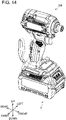
- the battery pack 2 is configured to be dismountably mounted on a power tool 200.
- the power tool 200 is a power screw driver
- the power tool 200 may for example be a power drill, a power grinder, a power circular saw, a power chainsaw, a power reciprocating saw, a power mower, a power trimmer, or a power blower.
- the battery pack 2 supplies power to the power tool 200 when it is mounted on the power tool 200.
- a direction along which the power tool 200 is located as seen from the battery pack 2 when it is mounted on the power tool 200 will be termed 'upward', and a direction opposite thereto will be termed 'downward'.
- a direction along which the battery pack 2 is slid upon when it is to be mounted on the power tool 200 will be termed 'rearward', and a direction along which the battery pack 2 is slid upon when it is to be dismounted from the power tool 200 will be termed 'frontward'. That is, in the following description, a front-rear direction corresponds to a sliding direction along which the battery pack 2 is slid with respect to the power tool 200.
- the battery pack 2 comprises a battery module 10 (see FIG. 5 ) and an outer case 12 (see FIG. 1 ) that houses the battery module 10.
- the outer case 12 has a substantially cuboid shape as a whole, and is divided into an upper case 14 and a lower case 16.
- the upper case 14 and the lower case 16 are fixed to each other by metal screws 18 (see FIG. 2 ).
- the upper case 14 includes slide rails 20, a terminal reception part 22, and a hook 24.
- the slide rails 20 extend in the front-rear direction, and are respectively disposed at upper left and right ends of the upper case 14.
- the slide rails 20 are configured to slidably engage with slide rails of the power tool 200 (omitted from drawings) upon when the battery pack 2 is to be mounted on or dismounted from the power tool 200.
- the terminal reception part 22 includes terminal openings 22a defined in an upper surface 14a of the upper case 14.
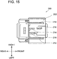
- the terminal openings 22a are disposed between the left and right slide rails 20, and are configured to receive a terminal unit 202 of the power tool 200 (see FIG. 15 ) when the battery pack 2 is to be mounted on the power tool 200.
- the hook 24 is disposed at a front upper portion of the upper case 14.
- the hook 24 is a resin member, and includes an operable part 24a and a protruding part 24b. The hook 24 is held by the upper case 14 so as to be movable in an up-down direction.
- the hook 24 is biased upward by a compression spring that is not shown, and is configured to move downward when the operable part 24a and/or the protruding part 24b are pressed downward.
- the protruding part 24b is configured to engage with an engaging groove (omitted from drawings) defined in a housing of the power tool 200 when the battery pack 2 is mounted on the power tool 200 and fix the battery pack 2 on the power tool 200.
- the protruding part 24b moves downward when a user presses down the operable part 24a.
- the battery pack 2 can be dismounted from the power tool 200 by sliding the battery pack 2 in this state.
- the operable part 24a has an inwardly depressed shape. Due to this, when the user is to press down the operable part 24a by placing a finger on the operable part 24a, the operable part 24a can be pressed down without the finger slipping.
- a display unit 30 is arranged on a front surface of the lower case 16.
- the display unit 30 includes a remaining charge indicator 30a for presenting remaining charge of the battery pack 2 and a button 30b for switching on/off of indication of the remaining charge.
- a plurality of holes 32 is defined in a bottom surface 16a of the lower case 16.
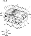
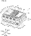
- the battery module 10 comprises a cell case 60, a control board 62, a LED board 64, a plurality of terminals 66, and a terminal cover 68.
- the cell case 60 is constituted of an insulative material, and may for example be constituted of a resin material.
- the cell case 60 is divided into a right cell case 70 and a left cell case 72.
- the cell case 60 has ten battery cells 90a to 90j disposed side by side therein in two vertical rows.
- the battery cells 90 are substantially cylindrical secondary battery cells, each having a positive electrode at one end and a negative electrode at another end, and are for example lithium ion battery cells.
- the battery cells 90 are type 18650 lithium ion battery cells, and their rated voltage is 3.6[V].
- the battery cells 90 are disposed such that a direction from the positive electrode to the negative electrode of each battery cell 90 is opposite to that of the battery cell 90 adjacent thereto in the up-down direction.
- the battery cells 90a to 90e in a lower row are disposed such that the direction from the positive electrode to the negative electrode of the battery cells 90b to 90e is opposite to the direction from the positive electrode to the negative electrode of the rearmost battery cell 90a.
- the battery cells 90f to 90j in an upper row are disposed such that the direction from the positive electrode to the negative electrode of the battery cells 90g to 90j is opposite to the direction from the positive electrode to the negative electrode of the rearmost battery cell 90f.
- the battery cells 90a, 90g to 90j are disposed such that their direction from the positive electrode to the negative electrode is in a same direction
- the battery cells 90b to 90f are disposed such that their direction from the positive electrode to the negative electrode is in the opposite to that of the battery cells 90a, 90g to 90j.
- the one ends of the battery cells 90 are connected to metal lead plates 92a to 92f disposed on a right side surface of the cell case 60 (see FIG. 5 )
- the other ends of the battery cells 90 are connected to metal lead plates 92g to 92k disposed on a left side surface of the cell case 60 (see FIG. 6 ). As shown in FIG.
- the plurality of lead plates 92a to 92f is disposed with an interval between each other. As such, the plurality of lead plates 92a to 92f is insulated from each other. Further, as shown in FIG. 6 , the plurality of lead plates 92g to 92k is disposed with an interval between each other. As such, the plurality of lead plates 92g to 92k is insulated from each other.
- the battery cells 90 are electrically connected in series by the lead plates 92a to 92k. Due to this, the rated voltage of the battery pack 2 is 36[V].
- insulative sheets are adhered on a right side surface 60a and a left side surface 60b of the cell case 60.
- the control board 62 is disposed above the cell case 60.
- the control board 62 is disposed along a plane that is perpendicular to the up-down direction.
- the control board 62 is fixed to the cell case 60 by screws 96.
- an element area EA double dot chain line on the control board 62
- electronic components such as a resistance, a capacitor, and a diode are arranged is disposed in front of the plurality of terminals 66.
- the element area EA is given waterproof coating.
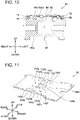
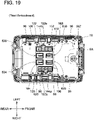
- the control board 62 includes terminal connectors 142a to 1421 for connecting the plurality of terminals 66 to the control board 62. Further, the control board 62 includes board holes 144a, 144b, 146a, 146b. The board holes 144a, 144b are each located on an outer side than their corresponding one of the board holes 146a, 146b is in a left-right direction. The board hole 144a on a right end side is located on the outer side (right side) than the terminal connectors 142a, 142b located rightmost among the terminal connectors 142a to 1421 are.
- the board hole 144b on a left end side is located on the outer side (left side) than the terminal connectors 142k, 1421 located leftmost among the terminal connectors 142a to 1421 are.
- the board hole 146a is disposed between the terminal connector 142d and the terminal connector 142e.
- the board hole 146b is disposed between the terminal connector 142h and the terminal connector 142i. Positions of the board holes 144a, 144b, 146a, 146b in the front-rear direction substantially coincide with one another.
- the plurality of terminals 66 is disposed on an upper surface of the control board 62.
- the terminals 66 are composed of a battery-side negative electrode terminal 100 used for charging and discharging power, a battery-side positive electrode terminal 102 used for charging and discharging power, and battery-side signal terminals 104, 106, 108, 110 used for signal transmission.
- the battery-side signal terminal 110 is not used when the battery pack 2 is mounted on the power tool 200.
- the battery-side signal terminal 110 is used only when the battery pack 2 is mounted on a charger (omitted from drawings).
- the battery-side negative electrode terminal 100 and the battery-side positive electrode terminal 102 function as a pair of discharging terminals.
- the battery-side negative electrode terminal 100 is connected to the terminal connectors 142a, 142b of the control board 62 (see FIG. 11 ), and the battery-side positive electrode terminal 102 is connected to the terminal connectors 142k, 1421 of the control board 62 (see FIG. 11 )
- the first battery-side signal terminal 104 is connected to the terminal connectors 142c, 142d of the control board 62 (see FIG. 11 ), the second battery-side signal terminal 106 is connected to the terminal connectors 142e, 142f of the control board 62 (see FIG.
- the third battery-side signal terminal 108 is connected to the terminal connectors 142g, 142h of the control board 62 (see FIG. 11 ), and the fourth battery-side signal terminal 110 is connected to the terminal connectors 142i, 142j of the control board 62 (see FIG. 11 ).
- the terminal cover 68 is provided at the upper surface of the control board 62.
- the terminal cover 68 is constituted of semitransparent resin.
- the terminal cover 68 is adhered to the control board 62 by double-sided tape. When the terminal cover 68 is semitransparent, an adhered state of the terminal cover 68 on the control board 62 can easily be checked.
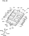
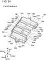
- the terminal cover 68 includes six peripheral walls 120, 122, 124, 126, 128, 130, two extension walls 132a, 132b, and coupling parts 134.
- the peripheral wall 120 is composed of a front wall 120a, a right wall 120b, a rear wall 120c, and a left wall 120d.
- a protruding part 120e protruding to an outer side (right side) is disposed at a center of the right wall 120b in the front-rear direction.
- the extension wall 132a extends toward the outer side of (right side) from the protruding part 120e.
- an opening 136 is defined at a lower portion of the rear wall 120c.
- the peripheral wall 122 is composed of a front wall 122a, a right wall 122b, a rear wall 122c, and a left wall 122d.
- a protruding part 122e protruding to an outer side (left side) is disposed at a center of the left wall 122d in the front-rear direction.
- the extension wall 132b extends toward the outer side (left side) from the protruding part 122e.
- the peripheral wall 124 is composed of a front wall 124a, a right wall 124b, a rear wall 124c, and a left wall 124d.
- the peripheral wall 126 is composed of a right wall 126b, a rear wall 126c, and a left wall 126d.
- the peripheral wall 128 is composed of a front wall 128a, a right wall 128b, a rear wall 128c, and a left wall 128d.
- the peripheral wall 130 is composed of a right wall 130b, a rear wall 130c, and a left wall 130d.
- the front wall 124a of the peripheral wall 124 and the rear wall 126c of the peripheral wall 126 are integrated as one. Further, the front wall 128a of the peripheral wall 128 and the rear wall 130c of the peripheral wall 130 are integrated as one. A height of the rear walls 122c, 124c, 128c located rearmost within the terminal cover 68 is lower than a height of other walls.
- the coupling parts 134 are configured to couple the peripheral walls that are spaced apart from each other in the left-right direction. Specifically, the coupling part 134 located rightmost couples the left wall 120d of the peripheral wall 120 and the right walls 124b, 126b of the peripheral walls 124, 126.
- the coupling part 134 located at center couples the left walls 124d, 126d of the peripheral walls 124, 126 and the right walls 128b, 130b of the peripheral walls 128, 130. Further, the coupling part 134 located leftmost couples the left walls 128d, 130d of the peripheral walls 128, 130 and the right wall 122b of the peripheral wall 122.
- the battery-side negative electrode terminal 100 is disposed inside the peripheral wall 120.
- the battery-side negative electrode terminal 100 is surrounded by the peripheral wall 120 except for its rear lower portion.
- the board hole 144a is disposed inside the protruding part 120e of the peripheral wall 120.
- the battery-side positive electrode terminal 102 is disposed inside the peripheral wall 122.
- the battery-side positive electrode terminal 102 is surrounded fully around its four sides by the peripheral wall 122.
- the board hole 144b is disposed inside the protruding part 122e of the peripheral wall 122.
- the battery-side signal terminals 104, 106, 108, 110 are disposed inside the peripheral walls 124, 126, 128, 130.
- the first battery-side signal terminal 104 is surrounded fully around its four sides by the peripheral wall 124.
- the board hole 146a is disposed inside the peripheral wall 124 and in front of the first battery-side signal terminal 104.
- the second battery-side signal terminal 106 is surrounded by the peripheral wall 126 except for its front side.
- the third battery-side signal terminal 108 is surrounded fully around its four sides by the peripheral wall 128.
- the board hole 146b is disposed inside the peripheral wall 128 and in front of the third battery-side signal terminal 108.
- the fourth battery-side signal terminal 110 is surrounded by the peripheral wall 130 except for its front side.
- the battery-side negative electrode terminal 100, the battery-side positive electrode terminal 102, and the battery-side signal terminals 104, 106, 108 are connected to the terminal unit 202 of the power tool 200 (see FIG. 15 ), however, the fourth battery-side signal terminal 110 is not connected to the terminal unit 202 of the power tool 200. This is because as shown in FIG.
- the terminal unit 202 of the power tool 200 includes a tool-side negative electrode terminal 210 corresponding to the battery-side negative electrode terminal 100, a tool-side positive electrode terminal 212 corresponding to the battery-side positive electrode terminal 102, a first tool-side signal terminal 214 corresponding to the first battery-side signal terminal 104, a second tool-side signal terminal 216 corresponding to the second battery-side signal terminal 106, and a third tool-side signal terminal 218 corresponding to the third battery-side signal terminal 108, however, it does not include a tool-side signal terminal corresponding to the fourth battery-side signal terminal 110.
- the terminal cover 68 is configured to separate, among the plurality of terminals 66, the terminals that are connected to the terminal unit 202 of the power tool 200.
- the battery-side positive electrode terminal 102, the first battery-side signal terminal 104, and the third battery-side signal terminal 108 are surrounded fully around their four sides by the peripheral walls 122, 124, 128, thus are separated from other terminals.
- the opening 136 is defined at the lower portion of the rear wall 120c of the peripheral wall 120.
- the peripheral wall 126 does not have a front wall.
- the terminal cover 68 includes the extension walls 132a, 132b.
- Aright end of the extension wall 132a substantially matches a right end of the control board 62
- a left end of the extension wall 132b substantially matches a left end of the control board 62.
- the extension walls 132a, 132b suppress water from flowing from front to rear side and from rear to front side of the control board 62. Due to this, when the water that adhered to the upper surface of the control board 62 passes through the opening 136, flows around the outer side of the peripheral wall 120, and reaches the extension wall 132a, the water is inhibited from flowing forward by the extension wall 132a. Specifically, the water flows out to the right of the control board 62, that is, onto an upper surface 60c of the cell case 60.
- the battery-side negative electrode terminal 100 and the second battery-side signal terminal 106 can be said as being separated by the peripheral wall 120, peripheral wall 126, and the extension walls 132a, 132b.
- the cell case 60 is divided into the right cell case 70 and the left cell case 72.
- the upper surface 60c of the cell case 60 has a shape corresponding to longitudinal side surfaces of the battery cells 90.
- Protruding parts 74 protruding upward than the upper surface 60c of the cell case 60 are arranged at an upper portion of the right side surface 60a of the cell case 60.
- the protruding parts 74 are each disposed to traverse over two adjacent battery cells 90.
- the protruding parts 74 each have a case hole 76 penetrating the protruding part 74 in the left-right direction. As shown in FIG.
- protruding parts 78 protruding upward than the upper surface 60c of the cell case 60 are arranged at an upper portion of the left side surface 60b of the cell case 60.
- the protruding parts 78 are each disposed to traverse over two adjacent battery cells 90.
- the protruding parts 78 each have a case hole 80 penetrating the protruding part 78 in the left-right direction.
- the protruding parts 74, 78 each have a depressed portion 88.
- the depressed portions 88 have a shape corresponding to projections (omitted from drawings) arranged on a back side of the upper surface 14a of the upper case 14.
- the projections on the upper case 14 are received in the depressed portions 88 in the cell case 60. Due to this, even when a positional displacement occurs between the upper case 14 and the lower case 16 due to an impact from the power tool 200 having the battery pack 2 mounted thereon (see FIG. 14 ) being dropped, a positional displacement can be suppressed from occurring between the upper case 14 and the cell case 60.
- the upper case 14 can be suppressed from contacting the control board 62 that is fixed to the cell case 60. That is, the protruding parts 74, 78 and the depressed portions 88 are provided to suppress the positional displacement between the upper case 14 and the lower case 16.
- cavities 60e1 to 60e4 are defined in the upper surface 60c of the cell case 60 between each pair of adjacent battery cells 90.
- Protruding parts 82 that protrude upward than the upper surface 60c are arranged in the cavities 60e1 to 60e4.
- the protruding parts 82 are arranged at a center of the cell case 60 in the left-right direction.
- Each protruding part 82 has a case hole 84 penetrates through the protruding part 82 in the up-down direction.
- case holes 86 are defined in a lower surface 60d of the cell case 60 at positions opposed to the case holes 84.
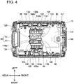
- a drain passage in a case where water that entered into the outer case 12 from the terminal openings 22a or the like flows through the board holes 144a, 144b, 146a, 146b of the control board 62 and reaches the upper surface 60c of the cell case 60 will be described with reference to FIGS. 4 , 9 , and 10 .
- the water that reached the upper surface 60c of the cell case 60 is collected in the cavities 60e1 to 60e4 in the upper surface 60c of the cell case 60.
- the water flows out to the lower case 16 side through the case holes 84 in the upper surface 60c of the cell case 60 and the case holes 86 in the lower surface 60d of the cell case 60.
- the water that flowed out to the lower case 16 reaches the bottom surface 16a of the lower case 16, and is drained to outside from the holes 32 in the bottom surface 16a (see FIG. 2 ).
- Most of the water flowing through the board holes 144a, 144b, 146a, 146b of the control board 62 is collected in the cavities 60e2, 60e3. As it is collected in the cavities 60e2, 60e3, the water flows out to the lower case 16 through the case holes 76 defined in the protruding parts 74 and the case holes 80 defined in the protruding parts 78 of the cell case 60.
- the water that flowed out to the lower case 16 reaches the bottom surface 16a of the lower case 16 and is drained to the outside from the holes 32 in the bottom surface 16a (see FIG. 2 ).
- draining performance of the upper surface 60c of the cell case 60 is increased by the case holes 76 of the right side surface 60a and the case holes 80 of the left side surface 60b of the cell case 60.
- the battery pack 2 comprises: the battery cells 90; the control board 62 disposed above the battery cells 90 and connected to the battery cells 90; the plurality of terminals 66 disposed on the control board 62 and disposed side by side in the left-right direction; the plurality of right walls 120b, 122b, 124b, 126b, 128b, 130b disposed on the control board 62; the plurality of left walls 120d, 122d, 124d, 126d, 128d, 130d disposed on the control board 62; and the outer case 12 having the upper surface 14a comprising the terminal reception part 22 configured to receive the terminal unit 202 of the power tool 200.
- At least two walls are disposed between two terminals adjacent in the left-right direction (for example, between the battery-side negative electrode terminal 100 and the third battery-side signal terminal 108).
- a long creepage distance between the two terminals adjacent in the left-right direction can be set longer than in a case where there is only one wall or no wall. Due to this, even when water entered into the outer case 12, the terminals adjacent in the left-right direction can be suppressed from being short-circuited.
- the plurality of right walls 120b, 122b, 124b, 126b, 128b, 130b and the plurality of left walls 120d, 122d, 124d, 126d, 128d, 130d are examples of "plurality of partition walls”.
- the battery-side negative electrode terminal 100, the battery-side positive electrode terminal 102, and the battery-side signal terminals 104, 106, 108, 110 are examples of "first terminal”.
- the battery-side negative electrode terminal 100, the battery-side positive electrode terminal 102, and the battery-side signal terminals 104, 106, 108, 110 are examples of "second terminal".
- the battery pack 2 comprises: the battery cells 90; the control board 62 disposed above the battery cells 90 and connected to the battery cells 90; the plurality of terminals 66 disposed on the control board 62; the peripheral walls 122, 124, 128 disposed on the control board 62 and surrounding the periphery of one terminal among the plurality of terminals 66; and the outer case 12 having the upper surface 14a comprising the terminal reception part 22 configured to receive the terminal unit 202 of the power tool 200.
- the board holes 144b, 146a, 146b are defined in the control board 62 that is inside the peripheral walls 122, 124, 128.
- a creepage distance between the battery-side positive electrode terminal 102, the first battery-side signal terminal 104, and the third battery-side signal terminal 108 surrounded by the peripheral walls 122, 124, 128 and the other terminals can be set longer than in a case where the peripheral walls 122, 124, 128 are not disposed. Further, since the board holes 144b, 146a, 146b are defined on the control board 62 on the inside of the peripheral walls 122, 124, 128, water does not stay inside the peripheral walls 122, 124, 128.
- the water that has been collected inside the peripheral walls 122, 124, 128 can be suppressed from overflowing to the outside of the peripheral walls 122, 124, 128 and the terminals 102, 104, 108 surrounded by the peripheral walls 122, 124, 128 can be suppressed from short-circuiting with the other terminals via the water.
- the battery pack 2 comprises: the cell case 60 housed inside the outer case 12, holding the ten battery cells 90, and disposed below the control board 62.
- the ten battery cells 90 are disposed parallel to the bottom surface 16a of the outer case 12, and the case holes 76, 80, 84, 86 are defined in the cell case 60 between the pairs of adjacent battery cells 90.
- the water drained from the board holes 144b, 146a, 146b of the control board 62 reaches the upper surface 60c of the cell case 60.
- the water that reached the upper surface 60c of the cell case 60 flows out to the bottom surface 16a of the outer case 12 through the case holes 76, 80, 84, 86 defined in the cell case 60.
- the water can be guided to a position lower than the control board 62 and the battery cells 90.
- the cell case 60 comprises: the case holes 84 disposed in the cavities 60e1 to 60e4 of the upper surface 60c of the cell case 60 between the pairs of adjacent battery cells 90 and penetrating through the cell case 60 in the up-down direction; and the case holes 86 disposed at the positions opposed to the case holes 84 in the lower surface 60d of the cell case 60 and penetrating through the cell case 60 in the up-down direction.
- the water that reached the cavities 60e1 to 60e4 of the upper surface 60c of the cell case 60 enter into the cell case 60 through the case holes 84 defined in the cavities 60e1 to 60e4 of the upper surface 60c of the cell case 60, reaches around the case holes 86 defined in the lower surface 60d of the cell case 60, flows out to the outer case 12 through the case holes 84, and reaches the bottom surface 16a of the outer case 12.
- the water can be guided to a position lower than the control board 62 and the battery cells 90.
- the protruding parts 74, 78 extending upward are disposed at longitudinal ends of the battery cells 90 on the upper surface 60c of the cell case 60 between the pairs of adjacent battery cells 90.
- the protruding parts 74, 78 comprise the case holes 76, 80 penetrating through the cell case 60 in the longitudinal direction of the battery cells 90.
- the water that reached the upper surface 60c of the cell case 60 flow along the upper surface 60c of the cell case 60 and reaches the case holes 76, 80 defined in the protruding parts 74, 78, and flows out to the bottom surface 16a of the outer case 12 through the case holes 76, 80.
- the water can be guided to a position lower than the control board 62 and the battery cells 90.
- the peripheral walls 122, 124, 128 are examples of "first partition wall”.
- the case holes 84 are examples of "first case hole”.
- the case holes 86 are examples of "second case hole”.
- the case holes 76, 80 are examples of "third case hole”.
- the battery-side positive electrode terminal 102 and the battery-side signal terminals 104, 108 are examples of "first terminal”.
- the battery pack 2 comprises: the battery cells 90; the control board 62 disposed above the battery cells 90 and connected to the battery cells 90; the plurality of terminals 66 disposed on the control board 62; one or more walls disposed on the control board 62; and the outer case 12 having the upper surface comprising the terminal reception part 22 configured to receive the terminal unit 202 of the power tool 200.
- the plurality of terminals 66 includes the battery-side negative electrode terminal 100, the battery-side positive electrode terminal 102, and the battery-side signal terminals 104, 106, 108.
- the left wall 120d and the right wall 126b extending in the front-rear direction are disposed between the battery-side negative electrode terminal 100 and the second battery-side signal terminal 106 that are adjacent to each other in the left-right direction on the frontmost side, and the front wall 120a extending in the left-right direction is disposed in front of the battery-side negative electrode terminal 100 only. According to the above configuration, a creepage distance between the battery-side negative electrode terminal 100 and the second battery-side signal terminal 106 in the left-right direction can be set long by the left wall 120d and the right wall 126b.
- a creepage distance for a case where water flows around the left wall 120d and the right wall 126b between the battery-side negative electrode terminal 100 and the second battery-side signal terminal 106 can be set long by the front wall 120a. As such, in the event where water enters into the outer case 12, the battery-side negative electrode terminal 100 and the second battery-side signal terminal 106 that are adjacent to each other on the frontmost side can be suppressed from short-circuiting.
- the front wall 120a is disposed in front of the battery-side negative electrode terminal 100 while no wall is disposed in front of the second battery-side signal terminal 106. Due to this, an area within the control board 62 that can be used as the element area EA can be increased as compared to a case where walls are disposed in front of both the battery-side negative electrode terminal 100 and the second battery-side signal terminal 106 adjacent to each other on the frontmost side
- the board holes 144a, 144b are defined on the outer sides of the battery-side negative electrode terminal 100 and the battery-side positive electrode terminal 102 disposed on the outermost sides in the left-right direction. According to the above configuration, water can be suppressed from being collected around the battery-side negative electrode terminal 100 and the battery-side positive electrode terminal 102. Further, as compared to a case where board holes are defined in the control board 62 in front of the battery-side negative electrode terminal 100 and in front of the battery-side positive electrode terminal 102, an area within the control board 62 that can be used as the element area EA can be increased.
- the board hole 146a is defined in the control board 62 between two battery-side signal terminals 104, 106 adjacent to each other in the front-rear direction. According to the above configuration, as compared to a case of defining respective board holes in the control board 62 in front of each of the two battery-side signal terminals 104, 106 adjacent to each other in the front-rear direction, an area within the control board 62 that can be used as the element area EA can be increased.
- the battery-side negative electrode terminal 100 and the second battery-side signal terminal 106 are an example of "the (front) power terminal and the (front) signal terminal that are disposed side by side at the frontmost side”.
- the battery-side negative electrode terminal 100 is an example of "first power terminal”.
- the second battery-side signal terminal 106 is an example of "first signal terminal”.
- the left wall 120d and the right wall 126b are examples of "first front-rear directional partition wall”.
- the front wall 120a is an example of "left-right directional partition wall”.
- the battery-side negative electrode terminal 100 and the battery-side positive electrode terminal 102 are examples of "terminal disposed at an outermost side in the left-right direction”.
- the battery-side signal terminals 104, 106 are an example of "two terminals adjacent to each other in the front-rear direction".
- the board holes 144a, 144b are examples of "first board hole”.
- the board holes 146a, 146b are examples of "second board hole”.
- the battery pack 2 comprises: the battery cells 90; the control board 62 disposed above the battery cells 90 and connected to the battery cells 90; the plurality of terminals 66 disposed on the control board 62; the peripheral walls 120, 122, 124, 126, 128 disposed on the control board 62; the extension walls 132a, 132b disposed on the control board 62; and the outer case 12 having the upper surface 14a comprising the terminal reception part 22 configured to receive the terminal unit 202 of the power tool 200.
- all of the terminals 100, 102, 104, 106, 108 connected to the terminal unit 202 of the power tool 200 among the plurality of terminals 66 are partitioned from the other terminals by at least one wall. Due to this, creepage distances between the plurality of terminals 66 can be set long. Thus, the terminals inside the outer case 12 can be suppressed from short-circuiting in the event where water enters into the outer case 12.
- the height of the rear walls 122c, 124c, 128c located rearmost is lower than the height of the rear walls 120c, 126c located more on the front side than the rear walls 122c, 124c, 128c are.
- the rear walls 122c, 124c, 128c can be left contact-free from the terminal unit 202 of the power tool 200 or the like when the battery pack 2 is mounted on the power tool 200, and the creepage distances between the terminals can be secured to suppress the terminals connected to the terminal unit 202 of the power tool 200 from being short-circuited.
- the battery-side negative electrode terminal 100 and the battery-side positive electrode terminal 102 are examples of "power terminals”.
- the peripheral walls 120, 122, 124, 126, 128 and the extension walls 132a, 132b of the terminal cover 68 are examples of "partition walls”.
- the rear walls 122c, 124c, 128c are examples of "first left-right directional partition wall”.
- the rear walls 120c, 126c are examples of "second left-right directional partition wall”.
- a battery pack 2 of a second embodiment differs in a structure of its terminal cover 368 from the structure of the terminal cover 68 of the battery pack 2 of the first embodiment.
- the terminal cover 368 includes six peripheral walls 420, 122, 124, 426, 128, 430, two extension walls 132a, 132b, and coupling parts 134.
- the peripheral wall 420 is composed of a front wall 420a, a right wall 420b, a rear wall 420c, and a left wall 420d.
- a protruding part 420e protruding to the outer side (right side) is disposed at a center of the right wall 420b in the front-rear direction.
- no opening is defined at a lower portion of the rear wall 420c.
- FIG. 18 in the present embodiment, no opening is defined at a lower portion of the rear wall 420c.
- the peripheral wall 426 is composed of a front wall 426a, a right wall 426b, a rear wall 426c, and a left wall 426d.
- the peripheral wall 430 is composed of a front wall 430a, a right wall 430b, a rear wall 430c, and a left wall 430d.
- each of the terminals 100, 102, 104, 106, 110 is surrounded fully around its four sides by its corresponding one(s) of the peripheral walls 420, 122, 124, 426, 128, 430.
- the terminal cover 368 may not include the extension walls 132a, 132b.
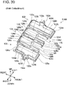
- a battery pack 2 of a third embodiment differs in structures of its control board 562 and terminal cover 568 from the structures of the control board 62 and the terminal cover 68 of the battery pack 2 of the first embodiment.
- the terminal cover 568 includes six peripheral walls 620, 122, 624, 626, 628, 630, two extension walls 132a, 132b, and coupling parts 134.
- the peripheral wall 620 is composed of a front wall 620a, a right wall 620b, a rear wall 620c, and a left wall 620d.
- a protruding part 620e protruding to the outer side (right side) is disposed at a center of the right wall 620b in the front-rear direction.
- no opening is defined at a lower portion of the rear wall 620c.
- the peripheral wall 624 is composed of a front wall 624a, a right wall 624b, a rear wall 624c, and a left wall 624d.
- the peripheral wall 626 is composed of a front wall 626a, a right wall 626b, a rear wall 626c, and a left wall 626d.
- the peripheral wall 628 is composed of a front wall 628a, a right wall 628b, a rear wall 628c, and a left wall 628d.
- the peripheral wall 630 is composed of a front wall 630a, a right wall 630b, a rear wall 630c, and a left wall 630d. This is different from the terminal cover 68 of the first embodiment (see FIG.
- each of the terminals 100, 102, 104, 106, 110 is surrounded fully around its four sides by its corresponding one(s) of the peripheral walls 620, 122, 624, 626, 628, 630.
- the board holes 146a, 146b are not defined in the control board 562 between the first battery-side signal terminal 104 and the second battery-side signal terminal 106 and also between the third battery-side signal terminal 108 and the fourth battery-side signal terminal 110.
- each of the terminals 100, 102, 104, 106, 110 is partitioned from the other terminals by two walls. With such a configuration as well, same effects as those of the battery pack 2 of the first embodiment can be achieved.
- the terminal cover 568 may not include the extension walls 132a, 132b.
- a battery pack 2 of a fourth embodiment differs in structures of its control board 762 and terminal cover 768 from the structures of the control board 62 and the terminal cover 68 of the battery pack 2 of the first embodiment.
- the terminal cover 768 of the present embodiment differs in a structure of its coupling parts 834 from the coupling parts 134 in the terminal cover 68 of the first embodiment. As shown in FIGS. 23 and 24 , an upper surface of each coupling part 834 has an inclined part 834a that is inclined such that its rear side is located lower than its front side.
- board holes 764 are defined in the control board 762.
- the board holes 764 are disposed more on the rear side than the inclined parts 834a of the coupling parts 834 are.
- an upper surface of each of the coupling parts 834 of the terminal cover 768 includes an inclined part 834a inclined such that the surface on the rear side is located lower than the surface on the front side.
- the inclined parts 834a are each inclined such that the surface on the rear side is located lower than the surface on the front side.
- the board holes 764 are defined in the control board 762 more on the rear side than the coupling parts 834 are. According to the above configuration, the water that reached the upper surfaces of the coupling parts 834 flows along the inclined parts 834a and out of the coupling parts 834, and flows through the board holes 764. As such, the water can be suppressed from being collected on an upper surface of the control board 762.
- the coupling part 834 located rightmost couples between the left wall 120d of the peripheral wall 120 and the right wall 126b of the peripheral wall 126, as well as between the left wall 120d of the peripheral wall 120 and the right wall 124b of the peripheral wall 124.
- water can be suppressed from being collected between the battery-side negative electrode terminal 100 and the second battery-side signal terminal 106 and also between the battery-side negative electrode terminal 100 and the first battery-side signal terminal 104.
- the terminals adjacent in the left-right direction can be suppressed from being short-circuited.
- the coupling part 834 located leftmost couples between the right wall 122b of the peripheral wall 122 and the left wall 130d of the peripheral wall 130 as well as between the right wall 122b of the peripheral wall 122 and the left wall 128d of the peripheral wall 128.
- water can be suppressed from being collected between the battery-side positive electrode terminal 102 and the fourth battery-side signal terminal 110 and also between the battery-side positive electrode terminal 102 and the third battery-side signal terminal 108.
- the terminals adjacent in the left-right direction can be suppressed from being short-circuited.
- the battery-side negative electrode terminal 100 is an example of "first terminal”.
- the second battery-side signal terminal 106 is an example of "second terminal”.
- the first battery-side signal terminal 104 is an example of "third terminal”.
- the left wall 120d is an example of "first partition wall extending in the front-rear direction”.
- the right wall 126b is an example of "second partition wall disposed between the first partition wall and the second terminal in the left-right direction and extending in the front-rear direction”.
- the right wall 124b is an example of "third partition wall disposed between the first partition wall and the third terminal in the left-right direction and extending in the front-rear direction”.
- the inclined parts 834a are examples of "inclined part”.
- the rear side is an example of "first direction”.
- the front side is an example of "second direction”.
- the board holes 764 are examples of "first control board hole”.
- the battery-side positive electrode terminal 102 is an example of "first terminal”.
- the fourth battery-side signal terminal 110 is an example of "second terminal adjacent to the first terminal in the left-right direction".
- the third battery-side signal terminal 108 is an example of "third terminal disposed side by side with the second terminal in the front-rear direction and adjacent to the first terminal in the left-right direction”.
- the peripheral wall 122 is an example of "first partition wall surrounding a periphery of the first terminal”.
- the left wall 130d is an example of "second partition wall disposed between the first partition wall and the second terminal".
- the left wall 128d is an example of "third partition wall disposed between the first partition wall and the third terminal”.
- the inclined parts 834a are examples of "inclined part".
- the rear side is an example of "first direction”.
- the front side is an example of "second direction”.
- the board holes 764 are examples of "first control board hole”.
- the battery-side negative electrode terminal 100 is an example of "first power terminal”.
- the second battery-side signal terminal 106 is an example of "first signal terminal”.
- the first battery-side signal terminal 104 is an example of "second signal terminal”.
- the left wall 120d is an example of "first front-rear directional partition wall”.
- the right wall 126b is an example of "second front-rear directional partition wall”.
- the right wall 124b is an example of "third front-rear directional partition wall”.
- the inclined parts 834a are examples of "inclined part".
- the rear side is an example of "first direction”.
- the front side is an example of "second direction”.
- the board holes 764 are examples of "first control board hole”.
- the battery-side negative electrode terminal 100 is an example of "first terminal”.
- the second battery-side signal terminal 106 is an example of "second terminal adjacent to the first terminal in the left-right direction".
- the first battery-side signal terminal 104 is an example of "third terminal disposed side by side with the second terminal in the front-rear direction and adjacent to the first terminal in the left-right direction”.
- the left wall 120d is an example of "first front-rear directional partition wall disposed between the first terminal and the second terminal, and extending in the front-rear direction”.
- the right wall 126b is an example of "second front-rear directional partition wall disposed between the first front-rear directional partition wall and the second terminal, and extending in the front-rear direction”.
- the right wall 124b is an example of "third front-rear directional partition wall disposed between the first front-rear directional partition wall and the third terminal, and extending in the front-rear direction".
- the inclined parts 834a are examples of "inclined part”.
- the rear side is an example of "first direction”.
- the front side is an example of "second direction”.
- the board holes 764 are examples of "first control board hole”.
- a battery pack 2 of a fifth embodiment differs in structures of its control board 962 and terminal cover 968 from the structures of the control board 62 and the terminal cover 68 of the battery pack 2 of the first embodiment.
- the terminal cover 968 of the present embodiment differs in a structure of its coupling parts 1034 from the structure of the coupling parts 134 of the terminal cover 68 of the first embodiment.
- an upper surface of each of the coupling parts 1034 is composed of a first inclined part 1034a inclined such that the surface on the front side is located lower than the surface on the rear side and a second inclined part 1034b inclined such that the surface on the rear side is located lower than the surface on the front side.
- the first inclined parts 1034a are disposed on the front side of the second inclined parts 1034b.
- board holes 964, 966 are defined in the control board 962.
- the board holes 964 are disposed more on the front side than the first inclined parts 1034a of the coupling parts 834 are.
- the board holes 966 are disposed more on the rear side than the second inclined parts 1034b of the coupling parts 834 are.
- the first inclined part 1034a and the second inclined part 1034b are arranged on the upper surface of each of the coupling parts 1034 of the terminal cover 968.
- the first inclined part 1034a arranged on the front side of the upper surface of each coupling part 1034 is inclined such that the surface on the front side is located lower than the surface on the rear side.
- the second inclined part 1034b arranged on the rear side of the upper surface of each coupling part 1034 is inclined such that the surface on the rear side is located lower than the surface on the front side.
- the upper surfaces of the coupling parts 1034 of the terminal cover 968 include the first inclined parts 1034a and the second inclined parts 1034b.
- the board holes 964 are defined in the control board 962 more on the front side than the coupling parts 1034 are.
- the board holes 966 are defined in the control board 962 more on the rear side than the coupling parts 1034 are.
- the first inclined parts 1034a and the second inclined parts 1034b are examples of "inclined part".
- the front side is an example of "first direction” and the rear side is an example of "second direction”.
- the second inclined parts 1034b are the example of the "inclined part”
- the rear side is the example of "first direction”
- the front side is the example of "second direction”.
- the board holes 964, 966 are examples of "first control board hole".
- a battery pack 2 of a sixth embodiment differs in structures of its control board 1162 and terminal cover 1168 from the structures of the control board 62 and the terminal cover 68 of the battery pack 2 of the first embodiment.
- the terminal cover 1168 of the present embodiment differs in a structure of its coupling parts 1234 from the structure of the coupling parts 134 of the terminal cover 68 of the first embodiment. As shown in FIGS. 28 to 30 , upper surfaces of the coupling parts 1234 are parallel to a plane including the front-rear direction and the left-right direction.
- Each coupling part 1234 includes a front cover hole 1236 and a rear cover hole 1238. These front cover hole 1236 and rear cover hole 1238 are disposed side by side in the front-rear direction. The front cover hole 1236 is disposed more on the front side than the rear cover hole 1238 is.
- board holes 1164, 1166 are defined in the control board 1162 below the coupling parts 1234.
- the board holes 1164, 1166 are disposed side by side in the front-rear direction.
- the board hole 1164 is disposed more on the front side than the board hole 1166 is.
- Each board hole 1164 is disposed below its corresponding front cover hole 1236 and each board hole 1166 is disposed below its corresponding rear cover hole 1238.
- a size of the board holes 1164, 1166 is larger than a size of the front cover hole 1236 and the rear cover hole 1238.
- the cover holes 1236, 1238 are defined in the coupling parts 1234 of the terminal cover 1168, and the board holes 1164, 1166 are defined in the control board 1162 below the cover holes 1236, 1238.
- water that reached the upper surfaces of the coupling parts 1234 flows through the cover holes 1236, 1238 and the board holes 1164, 1166. Due to this, the water can be suppressed from being collected on the upper surfaces of the coupling parts 1234. As such, the water that has been collected in the coupling parts 1234 can be suppressed from flowing over the walls.
- the cover holes 1236, 1238 are examples of "through hole”.
- the board holes 1164, 1166 are examples of "second control board hole”.
- the heights of the walls of the terminal cover 68 may all be same.
- the case holes 76, 80, 84, 86 may not be defined in the cell case 60. Further, in another variant, at least one of the case holes 76, 80, 84, 86 may not be defined.
- the protruding parts 74, 78 are disposed to suppress the positional displacement of the cell case 60 and the upper case 14.
- the protruding parts 74, 78 may be disposed to support the control board 62 that is to be set above the cell case 60, or may be disposed to increase a creepage distance between the lead plates 92 in the front-rear direction.
- the board holes 144a, 144b may be defined in front of or behind the battery-side negative electrode terminal 100 and the battery-side positive electrode terminal 102 located outermost in the left-right direction.
- the board holes 764, 964, 966 may not be defined in the control boards 762, 962.
- a part of the upper surfaces of the coupling parts 834 may be parallel to the plane including the front-rear direction and the left-right direction.
- the coupling parts 134, 834, 1034, 1234 of the respective embodiments may be coupled to only a part of the peripheral walls 120, 122, 124, 168, 128, 130 that are adjacent in the left-right direction.
- the coupling part 834 located rightmost may couple the left wall 120d of the peripheral wall 120 and the right wall 126b of the peripheral wall 126, however, it may not couple the left wall 120d of the peripheral wall 120 and the right wall 124b of the peripheral wall 124.
- the terminal cover 1168 of the sixth embodiment may not include the coupling parts 1234. That is, the peripheral wall 120 and the peripheral walls 124, 126 are not coupled. Further, the peripheral walls 124, 126 and the peripheral walls 128, 130 are not coupled. Further, the peripheral walls 128, 130 and the peripheral wall 122 are not coupled. Further, the board holes 1164, 1166 are defined in the control board 1162 that is between the peripheral wall 120 and the peripheral walls 124, 126, between the peripheral walls 124, 126 and the peripheral walls 128, 130, and between the peripheral walls 128, 130 and the peripheral wall 122.
- water that reached the control board 1162 between the left wall 120d of the peripheral wall 120 and the right wall 124b of the peripheral wall 124 flows through the board holes 1164, 1166 defined in the control board 1162 and reaches the upper surface 60c of the cell case 60.
Landscapes
- Chemical Kinetics & Catalysis (AREA)
- Electrochemistry (AREA)
- General Chemical & Material Sciences (AREA)
- Chemical & Material Sciences (AREA)
- Engineering & Computer Science (AREA)
- Biophysics (AREA)
- Life Sciences & Earth Sciences (AREA)
- Computer Hardware Design (AREA)
- Microelectronics & Electronic Packaging (AREA)
- Manufacturing & Machinery (AREA)
- Battery Mounting, Suspending (AREA)
- Connection Of Batteries Or Terminals (AREA)
- Portable Power Tools In General (AREA)
Abstract
Description
- The art disclosed herein relates to a battery pack.
-
Japanese Patent Application Publication No. 2011-9023 - In a battery pack as above, water may enter inside the outer case from the terminal reception part. When water enters inside the outer case, the terminals disposed on the control board could be short-circuited by the water.
- The description herein provides an art configured to suppress terminals inside an outer case from being short-circuited when water enters inside the outer case.
- A battery pack disclosed herein may be configured to be mounted on a power tool by being slid from front to rear. The battery pack may comprise: a battery cell; a control board disposed above the battery cell and connected to the battery cell; a plurality of terminals disposed on the control board and disposed side by side in a left-right direction; a plurality of partition walls disposed on the control board; and an outer case housing the battery cell, the control board, the plurality of terminals, and the plurality of partition walls, and having an upper surface comprising a terminal reception part configured to receive a terminal of the power tool, wherein the plurality of terminals includes a first terminal and a second terminal adjacent to the first terminal in the left-right direction, and at least two of the partition walls are disposed between the first terminal and the second terminal.
- In the above battery pack, a creepage distance between the first and second terminals adjacent to each other in the left-right direction can be set longer than in a case where there is only one partition wall and a case where there is no partition wall. Due to this, even when water enters inside the outer case, the terminals adjacent in the left-right direction can be suppressed from being short-circuited.
- Another battery pack disclosed herein may be configured to be mounted on a power tool by being slid. The battery pack may comprise: a battery cell; a control board disposed above the battery cell and connected to the battery cell; a plurality of terminals disposed on the control board; a first partition wall disposed on the control board and surrounding a periphery of the first terminal among the plurality of terminals; and an outer case having an upper surface comprising a terminal reception part configured to receive a terminal of the power tool, wherein a board hole is defined in the control board that is inside the first partition wall.
- In the battery pack with the above configuration, a creepage distance between the first terminal of which periphery is surrounded by the first partition wall and all other terminals can be set longer than in a case where there is no first partition wall. Further, since the board hole is defined in the control board inside the first partition wall, the water does not stay inside the first partition wall. Due to this, the water can be suppressed from being collected inside the first partition wall and overflowing to outside of the first partition wall, and the first terminal of which periphery is surrounded by the first partition wall can be suppressed from being short-circuited with the other terminals via the water.
- Another battery pack disclosed herein may be configured to be mounted on a power tool by being slid from front to rear. The battery pack may comprise: a battery cell; a control board disposed above the battery cell and connected to the battery cell; a plurality of terminals disposed on the control board; one or more partition walls disposed on the control board; and an outer case having an upper surface comprising a terminal reception part configured to receive a terminal of the power tool, wherein the plurality of terminals includes one or more power terminals and one or more signal terminals disposed side by side with the one or more power terminals in the left-right direction, a first front-rear directional partition wall extending in a front-rear direction is disposed between the power terminal and the signal terminal that are disposed side by side at a frontmost side among the power terminals and the signal terminals that are disposed side by side in the left-right direction, and a left-right directional partition wall extending in the left-right direction is disposed in front of one of the power terminal and the signal terminal that are disposed side by side at the frontmost side, and the left-right directional partition wall is not disposed in front of another of the power terminal and the signal terminal that are disposed side by side at the frontmost side.
- Water that entered into the outer case and reached the control board flows thereon in various directions in accordance with an orientation of the battery pack. Due to this, even when a front-rear directional partition wall is disposed between terminals, the water could flow around the front-rear directional partition wall and short-circuit the terminals. In the above battery pack, the first front-rear directional partition wall can set a long creepage distance in the left-right direction between the power terminal and the signal terminal disposed side by side at the frontmost side. Further, in the above battery pack, the left-right directional partition wall can set a long creepage distance between the power terminal and the signal terminal disposed side by side at the frontmost side for a case where water flows around the first front-rear directional partition wall. Thus, the power terminal and the signal terminal disposed side by side at the frontmost side can be suppressed from short-circuiting when the water enters into the outer case.
- Further, in the above configuration, the power tool is attached to a rear side of the battery pack. Moreover in general, in a control board, an element area where circuit elements are arranged is provided on an opposite side from the side where the power tool is to be attached. In the above configuration, the left-right directional partition wall is disposed in front of one of the power terminal and the signal terminal disposed side by side at the frontmost side while the left-right directional partition wall is not disposed in front of the other thereof. Due to this, an area within the control board that can be used as the element area can be increased as compared to a case where the left-right directional partition wall is disposed in front of both the power terminal and the signal terminal disposed side by side at the frontmost side.
- Another battery pack disclosed herein may be configured to be mounted on a power tool by being slid. The battery pack may comprise: a battery cell; a control board disposed above the battery cell and connected to the battery cell; a plurality of terminals disposed on the control board; one or more partition walls disposed on the control board; and an outer case housing the battery cell, the control board, the plurality of terminals, and the one or more partition walls, the outer case having an upper surface comprising a terminal reception part configured to receive a terminal of the power tool, wherein the plurality of terminals includes one or more power terminals configured to be connected to a terminal of the power tool and one or more signal terminals configured to be connected to a terminal of the power tool, and all of the plurality of the terminals are separated from other terminals by at least one partition wall.
- As a countermeasure for preventing short-circuit of the plurality of terminals, it is desirable to set a creepage distance between the plurality of terminals as long as possible. In the above battery pack, all of the plurality of terminals are separated from other terminals by at least one partition wall. Due to this, the creepage distance between the plurality of terminals can be set long. Thus, the terminals within the outer case can be suppressed from short-circuiting when the water enters into the outer case.
-
-
FIG. 1 is a perspective view seeing abattery pack 2 of a first embodiment from front right upper side. -
FIG. 2 is a bottom view seeing thebattery pack 2 of the first embodiment from below. -
FIG. 3 is a perspective view seeing abattery module 10 and alower case 16 from the front right upper side in the first embodiment. -
FIG. 4 is a top view seeing thebattery module 10 and thelower case 16 from above in the first embodiment. -
FIG. 5 is a perspective view seeing thebattery module 10 of the first embodiment from the front right upper side. -
FIG. 6 is a perspective view seeing thebattery module 10 of the first embodiment from rear left upper side. -
FIG. 7 is a cross-sectional view seeing thebattery module 10 of the first embodiment from right. -
FIG. 8 is a perspective view seeing acell case 60 of the first embodiment from the front right upper side. -
FIG. 9 is a top view seeing thecell case 60 of the first embodiment from above. -
FIG. 10 is a cross-sectional view seeing thecell case 60 from front in the first embodiment. -
FIG. 11 is a perspective view seeing acontrol board 62 of the first embodiment from the front right upper side. -
FIG. 12 is a perspective view seeing aterminal cover 68 of the first embodiment from the front right upper side. -
FIG. 13 is a perspective view seeing theterminal cover 68 of the first embodiment from rear right upper side. -
FIG. 14 is a perspective view from right upper front side seeing a state in which thebattery pack 2 of the first embodiment is mounted on apower tool 200. -
FIG. 15 is a bottom view seeing aterminal unit 202 of thepower tool 200 from below. -
FIG. 16 is a top view seeing abattery module 10 and alower case 16 from above in a second embodiment. -
FIG. 17 is a perspective view seeing aterminal cover 368 of the second embodiment from the front right upper side. -
FIG. 18 is a perspective view seeing theterminal cover 368 of the second embodiment from the rear right upper side. -
FIG. 19 is a top view seeing abattery module 10 and alower case 16 from above in a third embodiment. -
FIG. 20 is a perspective view seeing aterminal cover 568 of the third embodiment from the front right upper side. -
FIG. 21 is a perspective view seeing theterminal cover 568 of the third embodiment from the rear right upper side. -
FIG. 22 is a top view seeing abattery module 10 and alower case 16 from above in a fourth embodiment. -
FIG. 23 is a cross-sectional view along a line XXIII-XXIII inFIG. 22 . -
FIG. 24 is a perspective view seeing aterminal cover 768 of the fourth embodiment from the front right upper side. -
FIG. 25 is a top view seeing abattery module 10 and alower case 16 from above in a fifth embodiment. -
FIG. 26 is a cross-sectional view along a line XXVI-XXVI inFIG. 25 . -
FIG. 27 is a perspective view seeing aterminal cover 968 of the fifth embodiment from the front right upper side. -
FIG. 28 is a top view seeing abattery module 10 and alower case 16 from above in a sixth embodiment. -
FIG. 29 is a cross-sectional view along a line XXIX-XXIX inFIG. 28 . -
FIG. 30 is a perspective view seeing aterminal cover 1168 of the sixth embodiment from the front right upper side. - A battery pack disclosed herein may be configured to be mounted on a power tool by being slid from front to rear. The battery pack may comprise: a battery cell; a control board disposed above the battery cell and connected to the battery cell; a plurality of terminals disposed on the control board and disposed side by side in a left-right direction; a plurality of partition walls disposed on the control board; and an outer case housing the battery cell, the control board, the plurality of terminals, and the plurality of partition walls, and having an upper surface comprising a terminal reception part configured to receive a terminal of the power tool, wherein the plurality of terminals includes a first terminal and a second terminal adjacent to the first terminal in the left-right direction, and at least two of the partition walls are disposed between the first terminal and the second terminal.
- In one or more aspects, the at least two partition walls, which are disposed between the first terminal and the second terminal, may include a first partition wall extending in a front-rear direction and a second partition wall disposed between the first partition wall and the second terminal and extending in the front-rear direction. The battery pack may further comprise: a coupling part coupling the first partition wall and the second partition wall. An inclined part inclined in the front-rear direction may be disposed on at least a part of an upper surface of the coupling part.
- According to the above configuration, water that reached the upper surface of the coupling part flows along the inclined part and further flows out from the coupling part. Due to this, the water can be suppressed from being collected on the upper surface of the coupling part. Thus, the water that has been collected in the coupling part can be suppressed from flowing over the partition walls.
- In one or more aspects, the inclined part may be inclined such that a surface of the inclined part on a first direction side in the front-rear direction is located lower than a surface of the inclined part on a second direction side opposite to the first direction side. A first control board hole may be defined in the control board more on the first direction side than the coupling part is.
- According to the above configuration, the water that reached the upper surface of the coupling part flows along the inclined part and further flows out from the coupling part, and passes through the first control board hole. As such, the water can be suppressed from being collected on an upper surface of the control board.
- In one or more aspects, the at least two partition walls, which are disposed between the first terminal and the second terminal, may include a first partition wall extending in a front-rear direction and a second partition wall disposed between the first partition wall and the second terminal and extending in the front-rear direction. The battery pack may further comprise: a coupling part coupling the first partition wall and the second partition wall. A through hole may be defined in the coupling part. A second control board hole may be defined in the control board that is below the through hole.
- According to the above configuration, the water that reached the upper surface of the coupling part passes through the through hole and the second control board hole. Due to this, the water can be suppressed from being collected on the upper surface of the coupling part. As such, the water that has been collected in the coupling part can be suppressed from flowing over the partition walls.
- In one or more aspects, the plurality of terminals may include a third terminal disposed side by side with the second terminal in the front-rear direction and adjacent to the first terminal in the left-right direction. The first partition wall may extend in the front-rear direction such that the first partition wall is disposed between the first terminal and the second terminal and disposed between the first terminal and the third terminal. The plurality of partition walls may include a third partition wall disposed between the first partition wall and the third terminal and extending in the front-rear direction. The coupling part may couple the first partition wall and the third partition wall.
- According to the above configuration, water can be suppressed from being collected between the first and second terminals and also between the first and third terminals. As such, the terminals adjacent in the left-right direction can be suppressed from being short-circuited.
- Another battery pack disclosed herein may be configured to be mounted on a power tool by being slid. The battery pack may comprise: a battery cell; a control board disposed above the battery cell and connected to the battery cell; a plurality of terminals disposed on the control board; a first partition wall disposed on the control board and surrounding a periphery of the first terminal among the plurality of terminals; and an outer case having an upper surface comprising a terminal reception part configured to receive a terminal of the power tool, wherein a board hole is defined in the control board that is inside the first partition wall.
- In one or more aspects, the battery pack may further comprise a cell case housed inside the outer case, holding two or more of the battery cells, and disposed below the control board. The two or more battery cells may be disposed parallel to a bottom surface of the outer case and with an interval between each other. The cell case may comprise a case hole defined between two adjacent battery cells.
- Water that is drained from the board hole of the control board reaches an upper surface of the cell case. According to the above configuration, the water that reached the upper surface of the cell case passes through the case hole defined in the cell case and flows out to the bottom surface of the outer case. As such, the water can be guided to a position lower than the control board and the battery cell.
- In one or more aspects, the case hole of the cell case may comprise a first case hole defined in an upper surface of the cell case that is between the two adjacent battery cells and a second case hole defined in a lower surface of the cell case at a position opposed to the first case hole, in which the first case hole penetrates through the upper surface of the cell case in an up-down direction, and the second case hole penetrates through the lower surface of the cell case in the up-down direction.
- According to the above configuration, the water that reached the upper surface of the cell case passes through the first case hole and enters into the cell case, reaches around the second case hole and passes through the second case hole, flows out from the cell case, and reaches the bottom surface of the outer case. As such, the water can be guided to a position lower than the control board and the battery cell.
- In one or more aspects, a protruding part extending upward may be disposed on an upper surface of the cell case that is between the two adjacent battery cells at ends of the battery cells in a longitudinal direction. The case hole of the cell case may comprise a third case hole defined in the protruding part and penetrating through the protruding part in the longitudinal direction of the battery cells.
- According to the above configuration, the water that reached the upper surface of the cell case flows along the upper surface of the cell case and reaches the third case hole defined in the protruding part and passes through the third case hole, and further flows out to the bottom surface of the outer case. As such, the water can be guided to a position lower than the control board and the battery cell.
- In one or more aspects, the battery pack may be configured to be mounted on the power tool by being slid from front to rear. The plurality of terminals may include a second terminal adjacent to the first terminal in a left-right direction. The battery pack may further comprise: a second partition wall disposed between the first partition wall and the second terminal; and a coupling part coupling the first partition wall and the second partition wall. An inclined part inclined in the front-rear direction may be disposed on at least a part of an upper surface of the coupling part.
- According to the above configuration, the water that reached the upper surface of the coupling part flows along the inclined part and further flows out from the coupling part. Due to this, the water can be suppressed from being collected on the upper surface of the coupling part. As such, the water that has been collected in the coupling part can be suppressed from flowing over the partition walls.
- In one or more aspects, the inclined part may be inclined such that a surface of the inclined part on a first direction side in the front-rear direction is located lower than a surface of the inclined part on a second direction side opposite to the first direction side. A first control board hole may be defined in the control board more on the first direction side than the coupling part is.
- According to the above configuration, the water that reached the upper surface of the coupling part flows along the inclined part and further flows out from the coupling part, and passes through the first control board hole. As such, the water can be suppressed from being collected on the upper surface of the control board.
- In one or more aspects, the battery pack may be configured to be mounted on the power tool by being slid from front to rear. The plurality of terminals may include a second terminal adjacent to the first terminal in a left-right direction. The battery pack may further comprise: a second partition wall disposed between the first partition wall and the second terminal; and a coupling part coupling the first partition wall and the second partition wall. A through hole may be defined in the coupling part. A second control board hole may be defined in the control board that is below the through hole.
- According to the above configuration, the water that reached the upper surface of the coupling part passes through the through hole and the second control board hole. Due to this, the water can be suppressed from being collected on the upper surface of the coupling part. As such, the water that has been collected in the coupling part can be suppressed from flowing over the partition walls.
- In one or more aspects, the plurality of terminals may include a third terminal disposed side by side with the second terminal in the front-rear direction and adjacent to the first terminal in the left-right direction. The battery pack may further comprise: a third partition wall disposed between the first partition wall and the third terminal. The coupling part may couple the first partition wall and the third partition wall.
- According to the above configuration, water can be suppressed from being collected between the first and second terminals and also between the first and third terminals. As such, the terminals adjacent in the left-right direction can be suppressed from being short-circuited.
- Another battery pack disclosed herein may be configured to be mounted on a power tool by being slid from front to rear. The battery pack may comprise: a battery cell; a control board disposed above the battery cell and connected to the battery cell; a plurality of terminals disposed on the control board; one or more partition walls disposed on the control board; and an outer case having an upper surface comprising a terminal reception part configured to receive a terminal of the power tool, wherein the plurality of terminals includes one or more power terminals and one or more signal terminals disposed side by side with the one or more power terminals in the left-right direction, a first front-rear directional partition wall extending in a front-rear direction is disposed between the power terminal and the signal terminal that are disposed side by side at a frontmost side among the power terminals and the signal terminals that are disposed side by side in the left-right direction, and a left-right directional partition wall extending in the left-right direction is disposed in front of one of the power terminal and the signal terminal that are disposed side by side at the frontmost side, and the left-right directional partition wall is not disposed in front of another of the power terminal and the signal terminal that are disposed side by side at the frontmost side.
- In one or more aspects, the one or more power terminals may include a first power terminal that is the power terminal of the power terminal and the signal terminal that are adjacent to each other among the power terminal and the signal terminal disposed side by side at the frontmost side. The one or more signal terminals may include a first signal terminal that is the signal terminal of the power terminal and the signal terminal that are adjacent to each other. The first front-rear directional partition wall may be disposed between the first power terminal and the first signal terminal in the left-right direction. The left-right directional partition wall may be disposed in front of one of the first power terminal and the first signal terminal, and the left-right directional partition wall is not disposed in front of another of the first power terminal and the first signal terminal.
- According to the above configuration, the first front-rear directional partition wall can set a long creepage distance in the left-right direction between the first power terminal and the first signal terminal. Further, the left-right directional partition wall can set a long creepage distance between the first power terminal and the first signal terminal for a case where water flows around the first front-rear directional partition wall. Thus, the first power terminal and the first signal terminal can be suppressed from short-circuiting when the water enters into the outer case. Further, an area within the control board that can be used as an element area can be increased as compared to a case where the left-right directional partition wall is disposed in front of both the first power terminal and the first signal terminal.
- In one or more aspects, a first board hole may defined in the control board on an outer side of a terminal disposed at an outermost side in the left-right direction among the plurality of terminals.
- According to the above configuration, water can be suppressed from being collected around the terminal disposed at the outermost side in the left-right direction. Further, an area within the control board that can be used as the element area can be increased as compared to a case where the first board hole is defined in the control board in front of the terminal disposed at the outermost side in the left-right direction.
- In one or more aspects, a second board hole may be defined in the control board between two terminals adjacent to each other in the front-rear direction among the plurality of terminals.
- According to the above configuration, an area within the control board that can be used as the element area can be increased as compared to a case where a board hole is defined in the control board in front of each of the two terminals adjacent to each other in the front-rear direction.
- In one or more aspects, the one or more power terminals may include a first power terminal that is the power terminal of the power terminal and the signal terminal that are adjacent to each other among the power terminal and the signal terminal arranged side by side at the frontmost side. The one or more signal terminals may include a first signal terminal that is the signal terminal of the power terminal and the signal terminal that are adjacent to each other. The first front-rear directional partition wall may be disposed between the first power terminal and the first signal terminal in the left-right direction. A second front-rear directional partition wall extending in a front-rear direction may be disposed between the first front-rear directional partition wall and the first signal terminal. The battery pack may further comprise: a coupling part coupling the first front-rear directional partition wall and the second front-rear directional partition wall. An inclined part inclined in the front-rear direction may be disposed on at least a part of an upper surface of the coupling part.
- According to the above configuration, the water that reached the upper surface of the coupling part flows along the inclined part and further flows out from the coupling part. Due to this, the water can be suppressed from being collected on the upper surface of the coupling part. As such, the water that has been collected in the coupling part can be suppressed from flowing over the partition wall.
- In one or more aspects, the inclined part may be inclined such that a surface of the inclined part on a first direction side in the front-rear direction is located lower than a surface of the inclined part on a second direction side opposite to the first direction side. A first control board hole may be defined in the control board more on the first direction side than the coupling part is.
- According to the above configuration, the water that reached the upper surface of the coupling part flows along the inclined part and further flows out from the coupling part, and passes through the first control board hole. As such, the water can be suppressed from being collected on the upper surface of the control board.
- In one or more aspects, a second front-rear directional partition wall extending in a front-rear direction may be disposed between the first front-rear directional partition wall and the first signal terminal. The battery pack may further comprise: a coupling part coupling the first front-rear directional partition wall and the second front-rear directional partition wall. A through hole may be defined in the coupling part. A second control board hole may be defined in the control board that is below the through hole.
- According to the above configuration, the water that reached the upper surface of the coupling part passes through the through hole and the second control board hole. Due to this, the water can be suppressed from being collected on the upper surface of the coupling part. As such, the water that has been collected in the coupling part can be suppressed from flowing over the partition walls.
- In one or more aspects, the one or more signal terminals may include a second signal terminal disposed side by side with the first signal terminal in the front-rear direction and adjacent to the first power terminal in the left-right direction. The first front-rear directional partition wall may extend in the front-rear direction such that the first front-rear directional partition wall is disposed between the first power terminal and the first signal terminal and between the first power terminal and the second signal terminal. The battery pack may further comprise: a third front-rear directional partition wall disposed between the first front-rear directional partition wall and the second signal terminal. The coupling part may couple the first front-rear directional partition wall and the third front-rear directional partition wall.
- According to the above configuration, water can be suppressed from being collected between the first power terminal and the first signal terminal and between the first power terminal and the second signal terminal. As such, the terminals adjacent in the left-right direction can be suppressed from being short-circuited.
- Another battery pack disclosed herein may be configured to be mounted on a power tool by being slid. The battery pack may comprise: a battery cell; a control board disposed above the battery cell and connected to the battery cell; a plurality of terminals disposed on the control board; one or more partition walls disposed on the control board; and an outer case housing the battery cell, the control board, the plurality of terminals, and the one or more partition walls, the outer case having an upper surface comprising a terminal reception part configured to receive a terminal of the power tool, wherein the plurality of terminals includes one or more power terminals configured to be connected to a terminal of the power tool and one or more signal terminals configured to be connected to a terminal of the power tool, and all of the plurality of the terminals are separated from other terminals by at least one partition wall.
- In one or more aspects, the battery pack may be configured to be mounted on the power tool by being slid from front to rear. The one or more partition walls may include a plurality of left-right directional partition walls extending in a left-right direction, the plurality of left-right directional partition walls may include a first left-right directional partition wall disposed at a rearmost side and a second left-right directional partition wall disposed more on a front side than the first left-right directional partition wall is. A height of the first left-right directional partition wall may be lower than a height of the second left-right directional partition wall.
- In order to set a creepage distance that is as long as possible between the terminals, the partition walls are desirably as high as possible. However, since the power tool is attached to a rear side of the battery pack, the terminals of the power tool and the partition walls could interfere with each other if the rearmost left-right directional partition wall is designed to be high. According to the above configuration, the partition walls can be suppressed from interfering with the terminals of the power tool when the battery pack is mounted on the power tool, and further the creepage distance between the terminals can be secured to suppress short-circuiting of the plurality of terminals.
- In one or more aspects, the battery pack may be configured to be mounted on the power tool by being slid from front to rear. The one or more signal terminals may include a first terminal and a second terminal adjacent to the first terminal in a left-right direction. The one or more partition walls may include a first front-rear directional partition wall disposed between the first terminal and the second terminal and extending in a front-rear direction and a second front-rear directional partition wall disposed between the first front-rear directional partition wall and the second terminal and extending in the front-rear direction. The battery pack may further comprise: a coupling part coupling the first front-rear directional partition wall and the second front-rear directional partition wall. An inclined part inclined in the front-rear direction may be disposed on at least a part of an upper surface of the coupling part.
- According to the above configuration, the water that reached the upper surface of the coupling part flows along the inclined part and further flows out from the coupling part. Due to this, the water can be suppressed from being collected on the upper surface of the coupling part. Thus, the water that has been collected in the coupling part can be suppressed from flowing over the partition walls.
- In one or more aspects, the inclined part may be inclined such that a surface of the inclined part on a first direction side in the front-rear direction is located lower than a surface of the inclined part on a second direction side opposite to the first direction side. A first control board hole may be defined in the control board more on the first direction side than the coupling part is.
- According to the above configuration, the water that reached the upper surface of the coupling part flows along the inclined part and further flows out from the coupling part, and passes through the first control board hole. As such, the water can be suppressed from being collected on the upper surface of the control board.
- In one or more aspects, the battery pack may be configured to be mounted on the power tool by being slid from front to rear. The one or more signal terminals may include a first terminal and a second terminal adjacent to the first terminal in a left-right direction. The one or more partition walls may include a first front-rear directional partition wall disposed between the first terminal and the second terminal and extending in a front-rear direction and a second front-rear directional partition wall disposed between the first front-rear directional partition wall and the second terminal and extending in the front-rear direction. The battery pack may further comprise: a coupling part coupling the first front-rear directional partition wall and the second front-rear directional partition wall. A through hole may be defined in the coupling part. A second control board hole may be defined in the control board that is below the through hole.
- According to the above configuration, the water that reached the upper surface of the coupling part passes through the through hole and the second control board hole. Due to this, the water can be suppressed from being collected on the upper surface of the coupling part. Thus, the water that has been collected in the coupling part can be suppressed from flowing over the partition walls.
- In one or more aspects, the plurality of terminals may include a third terminal disposed side by side with the second terminal in the front-rear direction and adjacent to the first terminal in the left-right direction. The first front-rear directional partition wall may extend in the front-rear direction such that the first front-rear directional partition wall is disposed between the first terminal and the second terminal and between the first terminal and the third terminal. The battery pack may further comprise: a third front-rear directional partition wall disposed between the first front-rear directional partition wall and the third terminal and extending in the front-rear direction. The coupling part may couple the first front-rear directional partition wall and the third front-rear directional partition wall.
- According to the above configuration, the water can be suppressed from being collected between the first and second terminals and also between the first and third terminals. As such, the terminals adjacent in the left-right direction can be suppressed from being short-circuited.
- Hereinbelow, a
battery pack 2 of an embodiment will be described with reference to the drawings. As shown inFIG. 14 , thebattery pack 2 is configured to be dismountably mounted on apower tool 200. InFIG. 14 , a case in which thepower tool 200 is a power screw driver is exemplified, however, thepower tool 200 may for example be a power drill, a power grinder, a power circular saw, a power chainsaw, a power reciprocating saw, a power mower, a power trimmer, or a power blower. Thebattery pack 2 supplies power to thepower tool 200 when it is mounted on thepower tool 200. In the following description, with respect to thebattery pack 2, a direction along which thepower tool 200 is located as seen from thebattery pack 2 when it is mounted on thepower tool 200 will be termed 'upward', and a direction opposite thereto will be termed 'downward'. Further, with respect to thebattery pack 2, a direction along which thebattery pack 2 is slid upon when it is to be mounted on thepower tool 200 will be termed 'rearward', and a direction along which thebattery pack 2 is slid upon when it is to be dismounted from thepower tool 200 will be termed 'frontward'. That is, in the following description, a front-rear direction corresponds to a sliding direction along which thebattery pack 2 is slid with respect to thepower tool 200. - As shown in
FIGS. 1 to 13 , thebattery pack 2 comprises a battery module 10 (seeFIG. 5 ) and an outer case 12 (seeFIG. 1 ) that houses thebattery module 10. - As shown in
FIG. 1 , theouter case 12 has a substantially cuboid shape as a whole, and is divided into anupper case 14 and alower case 16. Theupper case 14 and thelower case 16 are fixed to each other by metal screws 18 (seeFIG. 2 ). - The
upper case 14 includes slide rails 20, aterminal reception part 22, and ahook 24. The slide rails 20 extend in the front-rear direction, and are respectively disposed at upper left and right ends of theupper case 14. The slide rails 20 are configured to slidably engage with slide rails of the power tool 200 (omitted from drawings) upon when thebattery pack 2 is to be mounted on or dismounted from thepower tool 200. - The
terminal reception part 22 includesterminal openings 22a defined in anupper surface 14a of theupper case 14. Theterminal openings 22a are disposed between the left and right slide rails 20, and are configured to receive aterminal unit 202 of the power tool 200 (seeFIG. 15 ) when thebattery pack 2 is to be mounted on thepower tool 200. Thehook 24 is disposed at a front upper portion of theupper case 14. Thehook 24 is a resin member, and includes anoperable part 24a and aprotruding part 24b. Thehook 24 is held by theupper case 14 so as to be movable in an up-down direction. Thehook 24 is biased upward by a compression spring that is not shown, and is configured to move downward when theoperable part 24a and/or theprotruding part 24b are pressed downward. The protrudingpart 24b is configured to engage with an engaging groove (omitted from drawings) defined in a housing of thepower tool 200 when thebattery pack 2 is mounted on thepower tool 200 and fix thebattery pack 2 on thepower tool 200. When thebattery pack 2 is to be dismounted from thepower tool 200, the protrudingpart 24b moves downward when a user presses down theoperable part 24a. Thebattery pack 2 can be dismounted from thepower tool 200 by sliding thebattery pack 2 in this state. Theoperable part 24a has an inwardly depressed shape. Due to this, when the user is to press down theoperable part 24a by placing a finger on theoperable part 24a, theoperable part 24a can be pressed down without the finger slipping. - A
display unit 30 is arranged on a front surface of thelower case 16. Thedisplay unit 30 includes a remainingcharge indicator 30a for presenting remaining charge of thebattery pack 2 and abutton 30b for switching on/off of indication of the remaining charge. As shown inFIG. 2 , a plurality ofholes 32 is defined in abottom surface 16a of thelower case 16. - As shown in
FIG. 5 , thebattery module 10 comprises acell case 60, acontrol board 62, aLED board 64, a plurality ofterminals 66, and aterminal cover 68. Thecell case 60 is constituted of an insulative material, and may for example be constituted of a resin material. Thecell case 60 is divided into aright cell case 70 and aleft cell case 72. - As shown in
FIG. 7 , thecell case 60 has tenbattery cells 90a to 90j disposed side by side therein in two vertical rows. The battery cells 90 are substantially cylindrical secondary battery cells, each having a positive electrode at one end and a negative electrode at another end, and are for example lithium ion battery cells. In the present embodiment, the battery cells 90 are type 18650 lithium ion battery cells, and their rated voltage is 3.6[V]. The battery cells 90 are disposed such that a direction from the positive electrode to the negative electrode of each battery cell 90 is opposite to that of the battery cell 90 adjacent thereto in the up-down direction. Thebattery cells 90a to 90e in a lower row are disposed such that the direction from the positive electrode to the negative electrode of thebattery cells 90b to 90e is opposite to the direction from the positive electrode to the negative electrode of therearmost battery cell 90a. Further, thebattery cells 90f to 90j in an upper row are disposed such that the direction from the positive electrode to the negative electrode of thebattery cells 90g to 90j is opposite to the direction from the positive electrode to the negative electrode of therearmost battery cell 90f. That is, thebattery cells battery cells 90b to 90f are disposed such that their direction from the positive electrode to the negative electrode is in the opposite to that of thebattery cells metal lead plates 92a to 92f disposed on a right side surface of the cell case 60 (seeFIG. 5 ), and the other ends of the battery cells 90 are connected tometal lead plates 92g to 92k disposed on a left side surface of the cell case 60 (seeFIG. 6 ). As shown inFIG. 5 , the plurality oflead plates 92a to 92f is disposed with an interval between each other. As such, the plurality oflead plates 92a to 92f is insulated from each other. Further, as shown inFIG. 6 , the plurality oflead plates 92g to 92k is disposed with an interval between each other. As such, the plurality oflead plates 92g to 92k is insulated from each other. The battery cells 90 are electrically connected in series by thelead plates 92a to 92k. Due to this, the rated voltage of thebattery pack 2 is 36[V]. Although not shown in the drawings, insulative sheets are adhered on aright side surface 60a and aleft side surface 60b of thecell case 60. - As shown in
FIG. 5 , thecontrol board 62 is disposed above thecell case 60. Thecontrol board 62 is disposed along a plane that is perpendicular to the up-down direction. Thecontrol board 62 is fixed to thecell case 60 byscrews 96. In thecontrol board 62, an element area EA (double dot chain line on the control board 62) where electronic components such as a resistance, a capacitor, and a diode are arranged is disposed in front of the plurality ofterminals 66. The element area EA is given waterproof coating. - As shown in
FIG. 11 , thecontrol board 62 includesterminal connectors 142a to 1421 for connecting the plurality ofterminals 66 to thecontrol board 62. Further, thecontrol board 62 includesboard holes board holes board hole 144a on a right end side is located on the outer side (right side) than theterminal connectors terminal connectors 142a to 1421 are. Further, theboard hole 144b on a left end side is located on the outer side (left side) than theterminal connectors terminal connectors 142a to 1421 are. Theboard hole 146a is disposed between theterminal connector 142d and theterminal connector 142e. Theboard hole 146b is disposed between theterminal connector 142h and theterminal connector 142i. Positions of theboard holes - As shown in
FIG. 5 , the plurality ofterminals 66 is disposed on an upper surface of thecontrol board 62. Theterminals 66 are composed of a battery-sidenegative electrode terminal 100 used for charging and discharging power, a battery-sidepositive electrode terminal 102 used for charging and discharging power, and battery-side signal terminals side signal terminal 110 is not used when thebattery pack 2 is mounted on thepower tool 200. The battery-side signal terminal 110 is used only when thebattery pack 2 is mounted on a charger (omitted from drawings). In a state where thepower tool 200 is attached to thebattery pack 2, the battery-sidenegative electrode terminal 100 and the battery-sidepositive electrode terminal 102 function as a pair of discharging terminals. The battery-sidenegative electrode terminal 100 is connected to theterminal connectors FIG. 11 ), and the battery-sidepositive electrode terminal 102 is connected to theterminal connectors FIG. 11 ) The first battery-side signal terminal 104 is connected to theterminal connectors FIG. 11 ), the second battery-side signal terminal 106 is connected to theterminal connectors FIG. 11 ), the third battery-side signal terminal 108 is connected to theterminal connectors FIG. 11 ), and the fourth battery-side signal terminal 110 is connected to theterminal connectors FIG. 11 ). - Further, the
terminal cover 68 is provided at the upper surface of thecontrol board 62. Theterminal cover 68 is constituted of semitransparent resin. Theterminal cover 68 is adhered to thecontrol board 62 by double-sided tape. When theterminal cover 68 is semitransparent, an adhered state of theterminal cover 68 on thecontrol board 62 can easily be checked. As shown inFIG. 12 , theterminal cover 68 includes sixperipheral walls extension walls coupling parts 134. Theperipheral wall 120 is composed of afront wall 120a, aright wall 120b, arear wall 120c, and aleft wall 120d. A protrudingpart 120e protruding to an outer side (right side) is disposed at a center of theright wall 120b in the front-rear direction. Theextension wall 132a extends toward the outer side of (right side) from the protrudingpart 120e. As shown inFIG. 13 , anopening 136 is defined at a lower portion of therear wall 120c. As shown inFIG. 12 , theperipheral wall 122 is composed of afront wall 122a, aright wall 122b, arear wall 122c, and aleft wall 122d. A protrudingpart 122e protruding to an outer side (left side) is disposed at a center of theleft wall 122d in the front-rear direction. Theextension wall 132b extends toward the outer side (left side) from the protrudingpart 122e. Theperipheral wall 124 is composed of afront wall 124a, aright wall 124b, arear wall 124c, and aleft wall 124d. Theperipheral wall 126 is composed of aright wall 126b, arear wall 126c, and aleft wall 126d. Theperipheral wall 128 is composed of afront wall 128a, aright wall 128b, arear wall 128c, and aleft wall 128d. Theperipheral wall 130 is composed of aright wall 130b, arear wall 130c, and aleft wall 130d. Thefront wall 124a of theperipheral wall 124 and therear wall 126c of theperipheral wall 126 are integrated as one. Further, thefront wall 128a of theperipheral wall 128 and therear wall 130c of theperipheral wall 130 are integrated as one. A height of therear walls terminal cover 68 is lower than a height of other walls. Thecoupling parts 134 are configured to couple the peripheral walls that are spaced apart from each other in the left-right direction. Specifically, thecoupling part 134 located rightmost couples theleft wall 120d of theperipheral wall 120 and theright walls peripheral walls coupling part 134 located at center couples theleft walls peripheral walls right walls peripheral walls coupling part 134 located leftmost couples theleft walls peripheral walls right wall 122b of theperipheral wall 122. - As shown in
FIG. 4 , in a state where theterminal cover 68 is attached to the upper surface of thecontrol board 62, the battery-sidenegative electrode terminal 100 is disposed inside theperipheral wall 120. The battery-sidenegative electrode terminal 100 is surrounded by theperipheral wall 120 except for its rear lower portion. Further, theboard hole 144a is disposed inside the protrudingpart 120e of theperipheral wall 120. The battery-sidepositive electrode terminal 102 is disposed inside theperipheral wall 122. The battery-sidepositive electrode terminal 102 is surrounded fully around its four sides by theperipheral wall 122. Further, theboard hole 144b is disposed inside the protrudingpart 122e of theperipheral wall 122. - The battery-
side signal terminals peripheral walls side signal terminal 104 is surrounded fully around its four sides by theperipheral wall 124. Further, theboard hole 146a is disposed inside theperipheral wall 124 and in front of the first battery-side signal terminal 104. The second battery-side signal terminal 106 is surrounded by theperipheral wall 126 except for its front side. The third battery-side signal terminal 108 is surrounded fully around its four sides by theperipheral wall 128. Further, theboard hole 146b is disposed inside theperipheral wall 128 and in front of the third battery-side signal terminal 108. The fourth battery-side signal terminal 110 is surrounded by theperipheral wall 130 except for its front side. - As mentioned above, among the plurality of
terminals 66 disposed on thecontrol board 62, the battery-sidenegative electrode terminal 100, the battery-sidepositive electrode terminal 102, and the battery-side signal terminals terminal unit 202 of the power tool 200 (seeFIG. 15 ), however, the fourth battery-side signal terminal 110 is not connected to theterminal unit 202 of thepower tool 200. This is because as shown inFIG. 15 , theterminal unit 202 of thepower tool 200 includes a tool-sidenegative electrode terminal 210 corresponding to the battery-sidenegative electrode terminal 100, a tool-sidepositive electrode terminal 212 corresponding to the battery-sidepositive electrode terminal 102, a first tool-side signal terminal 214 corresponding to the first battery-side signal terminal 104, a second tool-side signal terminal 216 corresponding to the second battery-side signal terminal 106, and a third tool-side signal terminal 218 corresponding to the third battery-side signal terminal 108, however, it does not include a tool-side signal terminal corresponding to the fourth battery-side signal terminal 110. Theterminal cover 68 is configured to separate, among the plurality ofterminals 66, the terminals that are connected to theterminal unit 202 of thepower tool 200. As shown inFIG. 4 , the battery-sidepositive electrode terminal 102, the first battery-side signal terminal 104, and the third battery-side signal terminal 108 are surrounded fully around their four sides by theperipheral walls negative electrode terminal 100, theopening 136 is defined at the lower portion of therear wall 120c of theperipheral wall 120. Further, as for the second battery-side signal terminal 106, theperipheral wall 126 does not have a front wall. Due to this, if theextension walls control board 62 could enter through theopening 136, flow around the outer side of theperipheral wall 120 or theperipheral wall 122, and reach theperipheral wall 126. This brings forth a risk that the battery-sidenegative electrode terminal 100 and the second battery-side signal terminal 106 short-circuit via the water. In order to avoid such a situation, theterminal cover 68 includes theextension walls extension wall 132a substantially matches a right end of thecontrol board 62, and a left end of theextension wall 132b substantially matches a left end of thecontrol board 62. Due to this, theextension walls control board 62. Due to this, when the water that adhered to the upper surface of thecontrol board 62 passes through theopening 136, flows around the outer side of theperipheral wall 120, and reaches theextension wall 132a, the water is inhibited from flowing forward by theextension wall 132a. Specifically, the water flows out to the right of thecontrol board 62, that is, onto anupper surface 60c of thecell case 60. Thus, the battery-sidenegative electrode terminal 100 and the second battery-side signal terminal 106 can be said as being separated by theperipheral wall 120,peripheral wall 126, and theextension walls - As shown in
FIG. 8 , thecell case 60 is divided into theright cell case 70 and theleft cell case 72. Theupper surface 60c of thecell case 60 has a shape corresponding to longitudinal side surfaces of the battery cells 90. Protrudingparts 74 protruding upward than theupper surface 60c of thecell case 60 are arranged at an upper portion of theright side surface 60a of thecell case 60. The protrudingparts 74 are each disposed to traverse over two adjacent battery cells 90. The protrudingparts 74 each have acase hole 76 penetrating the protrudingpart 74 in the left-right direction. As shown inFIG. 6 , protrudingparts 78 protruding upward than theupper surface 60c of thecell case 60 are arranged at an upper portion of theleft side surface 60b of thecell case 60. The protrudingparts 78 are each disposed to traverse over two adjacent battery cells 90. The protrudingparts 78 each have acase hole 80 penetrating the protrudingpart 78 in the left-right direction. The protrudingparts depressed portion 88. Thedepressed portions 88 have a shape corresponding to projections (omitted from drawings) arranged on a back side of theupper surface 14a of theupper case 14. When theupper case 14 and thecell case 60 are connected, the projections on theupper case 14 are received in thedepressed portions 88 in thecell case 60. Due to this, even when a positional displacement occurs between theupper case 14 and thelower case 16 due to an impact from thepower tool 200 having thebattery pack 2 mounted thereon (seeFIG. 14 ) being dropped, a positional displacement can be suppressed from occurring between theupper case 14 and thecell case 60. Thus, theupper case 14 can be suppressed from contacting thecontrol board 62 that is fixed to thecell case 60. That is, the protrudingparts depressed portions 88 are provided to suppress the positional displacement between theupper case 14 and thelower case 16. - As shown in
FIG. 9 , cavities 60e1 to 60e4 are defined in theupper surface 60c of thecell case 60 between each pair of adjacent battery cells 90. Protrudingparts 82 that protrude upward than theupper surface 60c are arranged in the cavities 60e1 to 60e4. The protrudingparts 82 are arranged at a center of thecell case 60 in the left-right direction. Each protrudingpart 82 has acase hole 84 penetrates through the protrudingpart 82 in the up-down direction. Further, as shown inFIG. 10 , case holes 86 are defined in alower surface 60d of thecell case 60 at positions opposed to the case holes 84. - Next, a drain passage in a case where water that entered into the
outer case 12 from theterminal openings 22a or the like flows through theboard holes control board 62 and reaches theupper surface 60c of thecell case 60 will be described with reference toFIGS. 4 ,9 , and10 . The water that reached theupper surface 60c of thecell case 60 is collected in the cavities 60e1 to 60e4 in theupper surface 60c of thecell case 60. As the water is collected in the cavities 60e1 to 60e4, the water flows out to thelower case 16 side through the case holes 84 in theupper surface 60c of thecell case 60 and the case holes 86 in thelower surface 60d of thecell case 60. The water that flowed out to thelower case 16 reaches thebottom surface 16a of thelower case 16, and is drained to outside from theholes 32 in thebottom surface 16a (seeFIG. 2 ). Most of the water flowing through theboard holes control board 62 is collected in the cavities 60e2, 60e3. As it is collected in the cavities 60e2, 60e3, the water flows out to thelower case 16 through the case holes 76 defined in the protrudingparts 74 and the case holes 80 defined in the protrudingparts 78 of thecell case 60. The water that flowed out to thelower case 16 reaches thebottom surface 16a of thelower case 16 and is drained to the outside from theholes 32 in thebottom surface 16a (seeFIG. 2 ). As such, draining performance of theupper surface 60c of thecell case 60 is increased by the case holes 76 of theright side surface 60a and the case holes 80 of theleft side surface 60b of thecell case 60. - In one or more aspects, as shown in
FIGS. 1 to 13 , thebattery pack 2 comprises: the battery cells 90; thecontrol board 62 disposed above the battery cells 90 and connected to the battery cells 90; the plurality ofterminals 66 disposed on thecontrol board 62 and disposed side by side in the left-right direction; the plurality ofright walls control board 62; the plurality ofleft walls control board 62; and theouter case 12 having theupper surface 14a comprising theterminal reception part 22 configured to receive theterminal unit 202 of thepower tool 200. At least two walls are disposed between two terminals adjacent in the left-right direction (for example, between the battery-sidenegative electrode terminal 100 and the third battery-side signal terminal 108). According to the above configuration, a long creepage distance between the two terminals adjacent in the left-right direction can be set longer than in a case where there is only one wall or no wall. Due to this, even when water entered into theouter case 12, the terminals adjacent in the left-right direction can be suppressed from being short-circuited. - The plurality of
right walls left walls negative electrode terminal 100, the battery-sidepositive electrode terminal 102, and the battery-side signal terminals negative electrode terminal 100, the battery-sidepositive electrode terminal 102, and the battery-side signal terminals - In one or more aspects, as shown in
FIGS. 1 to 13 , thebattery pack 2 comprises: the battery cells 90; thecontrol board 62 disposed above the battery cells 90 and connected to the battery cells 90; the plurality ofterminals 66 disposed on thecontrol board 62; theperipheral walls control board 62 and surrounding the periphery of one terminal among the plurality ofterminals 66; and theouter case 12 having theupper surface 14a comprising theterminal reception part 22 configured to receive theterminal unit 202 of thepower tool 200. The board holes 144b, 146a, 146b are defined in thecontrol board 62 that is inside theperipheral walls positive electrode terminal 102, the first battery-side signal terminal 104, and the third battery-side signal terminal 108 surrounded by theperipheral walls peripheral walls control board 62 on the inside of theperipheral walls peripheral walls peripheral walls peripheral walls terminals peripheral walls - In one or more aspects, as shown in
FIGS. 5 to 10 , thebattery pack 2 comprises: thecell case 60 housed inside theouter case 12, holding the ten battery cells 90, and disposed below thecontrol board 62. The ten battery cells 90 are disposed parallel to thebottom surface 16a of theouter case 12, and the case holes 76, 80, 84, 86 are defined in thecell case 60 between the pairs of adjacent battery cells 90. The water drained from the board holes 144b, 146a, 146b of thecontrol board 62 reaches theupper surface 60c of thecell case 60. According to the above configuration, the water that reached theupper surface 60c of thecell case 60 flows out to thebottom surface 16a of theouter case 12 through the case holes 76, 80, 84, 86 defined in thecell case 60. As such, the water can be guided to a position lower than thecontrol board 62 and the battery cells 90. - In one or more aspects, as shown in
FIG. 10 , thecell case 60 comprises: the case holes 84 disposed in the cavities 60e1 to 60e4 of theupper surface 60c of thecell case 60 between the pairs of adjacent battery cells 90 and penetrating through thecell case 60 in the up-down direction; and the case holes 86 disposed at the positions opposed to the case holes 84 in thelower surface 60d of thecell case 60 and penetrating through thecell case 60 in the up-down direction. According to the above configuration, the water that reached the cavities 60e1 to 60e4 of theupper surface 60c of thecell case 60 enter into thecell case 60 through the case holes 84 defined in the cavities 60e1 to 60e4 of theupper surface 60c of thecell case 60, reaches around the case holes 86 defined in thelower surface 60d of thecell case 60, flows out to theouter case 12 through the case holes 84, and reaches thebottom surface 16a of theouter case 12. As such, the water can be guided to a position lower than thecontrol board 62 and the battery cells 90. - In one or more aspects, as shown in
FIGS. 5 to 10 , the protrudingparts upper surface 60c of thecell case 60 between the pairs of adjacent battery cells 90. The protrudingparts cell case 60 in the longitudinal direction of the battery cells 90. According to the above configuration, the water that reached theupper surface 60c of thecell case 60 flow along theupper surface 60c of thecell case 60 and reaches the case holes 76, 80 defined in the protrudingparts bottom surface 16a of theouter case 12 through the case holes 76, 80. As such, the water can be guided to a position lower than thecontrol board 62 and the battery cells 90. - The
peripheral walls positive electrode terminal 102 and the battery-side signal terminals - In one or more aspects, as shown in
FIGS. 1 to 13 , thebattery pack 2 comprises: the battery cells 90; thecontrol board 62 disposed above the battery cells 90 and connected to the battery cells 90; the plurality ofterminals 66 disposed on thecontrol board 62; one or more walls disposed on thecontrol board 62; and theouter case 12 having the upper surface comprising theterminal reception part 22 configured to receive theterminal unit 202 of thepower tool 200. The plurality ofterminals 66 includes the battery-sidenegative electrode terminal 100, the battery-sidepositive electrode terminal 102, and the battery-side signal terminals left wall 120d and theright wall 126b extending in the front-rear direction are disposed between the battery-sidenegative electrode terminal 100 and the second battery-side signal terminal 106 that are adjacent to each other in the left-right direction on the frontmost side, and thefront wall 120a extending in the left-right direction is disposed in front of the battery-sidenegative electrode terminal 100 only. According to the above configuration, a creepage distance between the battery-sidenegative electrode terminal 100 and the second battery-side signal terminal 106 in the left-right direction can be set long by theleft wall 120d and theright wall 126b. Further, a creepage distance for a case where water flows around theleft wall 120d and theright wall 126b between the battery-sidenegative electrode terminal 100 and the second battery-side signal terminal 106 can be set long by thefront wall 120a. As such, in the event where water enters into theouter case 12, the battery-sidenegative electrode terminal 100 and the second battery-side signal terminal 106 that are adjacent to each other on the frontmost side can be suppressed from short-circuiting. - Further, of the battery-side
negative electrode terminal 100 and the second battery-side signal terminal 106 adjacent to each other on the frontmost side, thefront wall 120a is disposed in front of the battery-sidenegative electrode terminal 100 while no wall is disposed in front of the second battery-side signal terminal 106. Due to this, an area within thecontrol board 62 that can be used as the element area EA can be increased as compared to a case where walls are disposed in front of both the battery-sidenegative electrode terminal 100 and the second battery-side signal terminal 106 adjacent to each other on the frontmost side - In one or more aspects, as shown in
FIG. 4 , theboard holes negative electrode terminal 100 and the battery-sidepositive electrode terminal 102 disposed on the outermost sides in the left-right direction. According to the above configuration, water can be suppressed from being collected around the battery-sidenegative electrode terminal 100 and the battery-sidepositive electrode terminal 102. Further, as compared to a case where board holes are defined in thecontrol board 62 in front of the battery-sidenegative electrode terminal 100 and in front of the battery-sidepositive electrode terminal 102, an area within thecontrol board 62 that can be used as the element area EA can be increased. - In one or more aspects, as shown in
FIG. 4 , theboard hole 146a is defined in thecontrol board 62 between two battery-side signal terminals control board 62 in front of each of the two battery-side signal terminals control board 62 that can be used as the element area EA can be increased. - The battery-side
negative electrode terminal 100 and the second battery-side signal terminal 106 are an example of "the (front) power terminal and the (front) signal terminal that are disposed side by side at the frontmost side". The battery-sidenegative electrode terminal 100 is an example of "first power terminal". The second battery-side signal terminal 106 is an example of "first signal terminal". Theleft wall 120d and theright wall 126b are examples of "first front-rear directional partition wall". Thefront wall 120a is an example of "left-right directional partition wall". The battery-sidenegative electrode terminal 100 and the battery-sidepositive electrode terminal 102 are examples of "terminal disposed at an outermost side in the left-right direction". The battery-side signal terminals - In one or more aspects, as shown in
FIGS. 1 to 13 , thebattery pack 2 comprises: the battery cells 90; thecontrol board 62 disposed above the battery cells 90 and connected to the battery cells 90; the plurality ofterminals 66 disposed on thecontrol board 62; theperipheral walls control board 62; theextension walls control board 62; and theouter case 12 having theupper surface 14a comprising theterminal reception part 22 configured to receive theterminal unit 202 of thepower tool 200. According to the above configuration, all of theterminals terminal unit 202 of thepower tool 200 among the plurality ofterminals 66 are partitioned from the other terminals by at least one wall. Due to this, creepage distances between the plurality ofterminals 66 can be set long. Thus, the terminals inside theouter case 12 can be suppressed from short-circuiting in the event where water enters into theouter case 12. - In one or more aspects, as shown in
FIG. 12 , the height of therear walls rear walls rear walls rear walls terminal unit 202 of thepower tool 200 or the like when thebattery pack 2 is mounted on thepower tool 200, and the creepage distances between the terminals can be secured to suppress the terminals connected to theterminal unit 202 of thepower tool 200 from being short-circuited. - The battery-side
negative electrode terminal 100 and the battery-sidepositive electrode terminal 102 are examples of "power terminals". Theperipheral walls extension walls terminal cover 68 are examples of "partition walls". Therear walls rear walls - Points that differ from the
battery pack 2 of the first embodiment will be described with reference toFIGS. 16 to 18 . Hereinbelow, configurations that are same between embodiments will be given same reference signs and description thereof will be omitted. Abattery pack 2 of a second embodiment differs in a structure of itsterminal cover 368 from the structure of theterminal cover 68 of thebattery pack 2 of the first embodiment. - As shown in
FIG. 17 , theterminal cover 368 includes sixperipheral walls extension walls coupling parts 134. Theperipheral wall 420 is composed of afront wall 420a, aright wall 420b, arear wall 420c, and aleft wall 420d. A protrudingpart 420e protruding to the outer side (right side) is disposed at a center of theright wall 420b in the front-rear direction. As shown inFIG. 18 , in the present embodiment, no opening is defined at a lower portion of therear wall 420c. As shown inFIG. 17 , theperipheral wall 426 is composed of afront wall 426a, aright wall 426b, arear wall 426c, and aleft wall 426d. Further, theperipheral wall 430 is composed of afront wall 430a, aright wall 430b, arear wall 430c, and aleft wall 430d. - As shown in
FIG. 16 , in a state where theterminal cover 368 is attached to the upper surface of thecontrol board 62, each of theterminals peripheral walls battery pack 2 of the first embodiment can be achieved. In a variant, theterminal cover 368 may not include theextension walls - Points that differ from the
battery pack 2 of the first embodiment will be described with reference toFIGS. 19 to 21 . Abattery pack 2 of a third embodiment differs in structures of itscontrol board 562 andterminal cover 568 from the structures of thecontrol board 62 and theterminal cover 68 of thebattery pack 2 of the first embodiment. - As shown in
FIG. 20 , theterminal cover 568 includes sixperipheral walls extension walls coupling parts 134. Theperipheral wall 620 is composed of afront wall 620a, aright wall 620b, arear wall 620c, and aleft wall 620d. A protrudingpart 620e protruding to the outer side (right side) is disposed at a center of theright wall 620b in the front-rear direction. As shown inFIG. 18 , no opening is defined at a lower portion of therear wall 620c. As shown inFIG. 17 , theperipheral wall 624 is composed of afront wall 624a, aright wall 624b, arear wall 624c, and aleft wall 624d. Theperipheral wall 626 is composed of afront wall 626a, aright wall 626b, arear wall 626c, and aleft wall 626d. Theperipheral wall 628 is composed of afront wall 628a, aright wall 628b, arear wall 628c, and aleft wall 628d. Theperipheral wall 630 is composed of afront wall 630a, aright wall 630b, arear wall 630c, and aleft wall 630d. This is different from theterminal cover 68 of the first embodiment (seeFIG. 12 ) in that thefront wall 624a of theperipheral wall 624 and therear wall 626c of theperipheral wall 626 are not integrated as one and thefront wall 628a of theperipheral wall 628 and therear wall 630c of theperipheral wall 630 are not integrated as one. - As shown in
FIG. 19 , in a state where theterminal cover 568 is attached to an upper surface of thecontrol board 562, each of theterminals peripheral walls board holes control board 562 between the first battery-side signal terminal 104 and the second battery-side signal terminal 106 and also between the third battery-side signal terminal 108 and the fourth battery-side signal terminal 110. According to the above configuration, each of theterminals battery pack 2 of the first embodiment can be achieved. In a variant, theterminal cover 568 may not include theextension walls - Points that differ from the
battery pack 2 of the first embodiment will be described with reference toFIGS. 22 to 24 . Abattery pack 2 of a fourth embodiment differs in structures of itscontrol board 762 andterminal cover 768 from the structures of thecontrol board 62 and theterminal cover 68 of thebattery pack 2 of the first embodiment. - The
terminal cover 768 of the present embodiment differs in a structure of itscoupling parts 834 from thecoupling parts 134 in theterminal cover 68 of the first embodiment. As shown inFIGS. 23 and24 , an upper surface of eachcoupling part 834 has aninclined part 834a that is inclined such that its rear side is located lower than its front side. - As shown in
FIGS. 22 and23 , board holes 764 are defined in thecontrol board 762. The board holes 764 are disposed more on the rear side than theinclined parts 834a of thecoupling parts 834 are. - In one or more aspects, as shown in
FIG. 23 , an upper surface of each of thecoupling parts 834 of theterminal cover 768 includes aninclined part 834a inclined such that the surface on the rear side is located lower than the surface on the front side. According to the above configuration, water that reached the upper surfaces of thecoupling parts 834 flows along theinclined parts 834a and out of thecoupling parts 834. Due to this, the water can be suppressed from being collected on the upper surfaces of thecoupling parts 834. Thus, the water that has been collected in thecoupling parts 834 can be suppressed from flowing over the walls. - In one or more aspects, as shown in
FIG. 23 , theinclined parts 834a are each inclined such that the surface on the rear side is located lower than the surface on the front side. The board holes 764 are defined in thecontrol board 762 more on the rear side than thecoupling parts 834 are. According to the above configuration, the water that reached the upper surfaces of thecoupling parts 834 flows along theinclined parts 834a and out of thecoupling parts 834, and flows through the board holes 764. As such, the water can be suppressed from being collected on an upper surface of thecontrol board 762. - In one or more aspects, as shown in
FIG. 24 , thecoupling part 834 located rightmost couples between theleft wall 120d of theperipheral wall 120 and theright wall 126b of theperipheral wall 126, as well as between theleft wall 120d of theperipheral wall 120 and theright wall 124b of theperipheral wall 124. According to the above configuration, water can be suppressed from being collected between the battery-sidenegative electrode terminal 100 and the second battery-side signal terminal 106 and also between the battery-sidenegative electrode terminal 100 and the first battery-side signal terminal 104. As such, the terminals adjacent in the left-right direction can be suppressed from being short-circuited. - Further, as shown in
FIG. 24 , thecoupling part 834 located leftmost couples between theright wall 122b of theperipheral wall 122 and theleft wall 130d of theperipheral wall 130 as well as between theright wall 122b of theperipheral wall 122 and theleft wall 128d of theperipheral wall 128. According to the above configuration, water can be suppressed from being collected between the battery-sidepositive electrode terminal 102 and the fourth battery-side signal terminal 110 and also between the battery-sidepositive electrode terminal 102 and the third battery-side signal terminal 108. As such, the terminals adjacent in the left-right direction can be suppressed from being short-circuited. - In one aspect, the battery-side
negative electrode terminal 100 is an example of "first terminal". The second battery-side signal terminal 106 is an example of "second terminal". The first battery-side signal terminal 104 is an example of "third terminal". Theleft wall 120d is an example of "first partition wall extending in the front-rear direction". Theright wall 126b is an example of "second partition wall disposed between the first partition wall and the second terminal in the left-right direction and extending in the front-rear direction". Theright wall 124b is an example of "third partition wall disposed between the first partition wall and the third terminal in the left-right direction and extending in the front-rear direction". Theinclined parts 834a are examples of "inclined part". The rear side is an example of "first direction". The front side is an example of "second direction". The board holes 764 are examples of "first control board hole". - Further, in another aspect, the battery-side
positive electrode terminal 102 is an example of "first terminal". The fourth battery-side signal terminal 110 is an example of "second terminal adjacent to the first terminal in the left-right direction". The third battery-side signal terminal 108 is an example of "third terminal disposed side by side with the second terminal in the front-rear direction and adjacent to the first terminal in the left-right direction". Theperipheral wall 122 is an example of "first partition wall surrounding a periphery of the first terminal". Theleft wall 130d is an example of "second partition wall disposed between the first partition wall and the second terminal". Theleft wall 128d is an example of "third partition wall disposed between the first partition wall and the third terminal". Theinclined parts 834a are examples of "inclined part". The rear side is an example of "first direction". The front side is an example of "second direction". The board holes 764 are examples of "first control board hole". - Further, in another aspect, the battery-side
negative electrode terminal 100 is an example of "first power terminal". The second battery-side signal terminal 106 is an example of "first signal terminal". The first battery-side signal terminal 104 is an example of "second signal terminal". Theleft wall 120d is an example of "first front-rear directional partition wall". Theright wall 126b is an example of "second front-rear directional partition wall". Theright wall 124b is an example of "third front-rear directional partition wall". Theinclined parts 834a are examples of "inclined part". The rear side is an example of "first direction". The front side is an example of "second direction". The board holes 764 are examples of "first control board hole". - Further, in another aspect, the battery-side
negative electrode terminal 100 is an example of "first terminal". The second battery-side signal terminal 106 is an example of "second terminal adjacent to the first terminal in the left-right direction". The first battery-side signal terminal 104 is an example of "third terminal disposed side by side with the second terminal in the front-rear direction and adjacent to the first terminal in the left-right direction". Theleft wall 120d is an example of "first front-rear directional partition wall disposed between the first terminal and the second terminal, and extending in the front-rear direction". Theright wall 126b is an example of "second front-rear directional partition wall disposed between the first front-rear directional partition wall and the second terminal, and extending in the front-rear direction". Theright wall 124b is an example of "third front-rear directional partition wall disposed between the first front-rear directional partition wall and the third terminal, and extending in the front-rear direction". Theinclined parts 834a are examples of "inclined part". The rear side is an example of "first direction". The front side is an example of "second direction". The board holes 764 are examples of "first control board hole". - Points that differ from the
battery pack 2 of the first embodiment will be described with reference toFIGS. 25 to 27 . Abattery pack 2 of a fifth embodiment differs in structures of itscontrol board 962 andterminal cover 968 from the structures of thecontrol board 62 and theterminal cover 68 of thebattery pack 2 of the first embodiment. - The
terminal cover 968 of the present embodiment differs in a structure of itscoupling parts 1034 from the structure of thecoupling parts 134 of theterminal cover 68 of the first embodiment. As shown inFIGS. 26 and27 , an upper surface of each of thecoupling parts 1034 is composed of a firstinclined part 1034a inclined such that the surface on the front side is located lower than the surface on the rear side and a secondinclined part 1034b inclined such that the surface on the rear side is located lower than the surface on the front side. The firstinclined parts 1034a are disposed on the front side of the secondinclined parts 1034b. - As shown in
FIGS. 25 and26 , board holes 964, 966 are defined in thecontrol board 962. The board holes 964 are disposed more on the front side than the firstinclined parts 1034a of thecoupling parts 834 are. The board holes 966 are disposed more on the rear side than the secondinclined parts 1034b of thecoupling parts 834 are. - In one or more aspects, as shown in
FIG. 26 , the firstinclined part 1034a and the secondinclined part 1034b are arranged on the upper surface of each of thecoupling parts 1034 of theterminal cover 968. The firstinclined part 1034a arranged on the front side of the upper surface of eachcoupling part 1034 is inclined such that the surface on the front side is located lower than the surface on the rear side. Further, the secondinclined part 1034b arranged on the rear side of the upper surface of eachcoupling part 1034 is inclined such that the surface on the rear side is located lower than the surface on the front side. According to the above configuration, water that reached the upper surfaces of thecoupling parts 1034 flows along the firstinclined parts 1034a and the secondinclined parts 1034b and out of thecoupling parts 1034. Due to this, the water can be suppressed from being collected on the upper surfaces of thecoupling parts 1034. As such, the water that has been collected in thecoupling parts 1034 can be suppressed from flowing over the walls. - In one or more aspects, as shown in
FIG. 26 , the upper surfaces of thecoupling parts 1034 of theterminal cover 968 include the firstinclined parts 1034a and the secondinclined parts 1034b. Further, the board holes 964 are defined in thecontrol board 962 more on the front side than thecoupling parts 1034 are. Further, the board holes 966 are defined in thecontrol board 962 more on the rear side than thecoupling parts 1034 are. According to the above configuration, the water that reached the upper surfaces of thecoupling parts 1034 flows along the firstinclined parts 1034a and the secondinclined parts 1034b and out of thecoupling parts 1034, and flows through the board holes 964, 966. As such, the water can be suppressed from being collected on an upper surface of thecontrol board 962. - The first
inclined parts 1034a and the secondinclined parts 1034b are examples of "inclined part". When the firstinclined parts 1034a are the example of the "inclined part", the front side is an example of "first direction" and the rear side is an example of "second direction". When the secondinclined parts 1034b are the example of the "inclined part", the rear side is the example of "first direction" and the front side is the example of "second direction". The board holes 964, 966 are examples of "first control board hole". - Points that differ from the
battery pack 2 of the first embodiment will be described with reference toFIGS. 28 to 30 . Abattery pack 2 of a sixth embodiment differs in structures of itscontrol board 1162 andterminal cover 1168 from the structures of thecontrol board 62 and theterminal cover 68 of thebattery pack 2 of the first embodiment. - The
terminal cover 1168 of the present embodiment differs in a structure of itscoupling parts 1234 from the structure of thecoupling parts 134 of theterminal cover 68 of the first embodiment. As shown inFIGS. 28 to 30 , upper surfaces of thecoupling parts 1234 are parallel to a plane including the front-rear direction and the left-right direction. Eachcoupling part 1234 includes afront cover hole 1236 and arear cover hole 1238. Thesefront cover hole 1236 andrear cover hole 1238 are disposed side by side in the front-rear direction. Thefront cover hole 1236 is disposed more on the front side than therear cover hole 1238 is. - As shown in
FIG. 29 ,board holes control board 1162 below thecoupling parts 1234. The board holes 1164, 1166 are disposed side by side in the front-rear direction. Theboard hole 1164 is disposed more on the front side than theboard hole 1166 is. Eachboard hole 1164 is disposed below its correspondingfront cover hole 1236 and eachboard hole 1166 is disposed below its correspondingrear cover hole 1238. A size of the board holes 1164, 1166 is larger than a size of thefront cover hole 1236 and therear cover hole 1238. - In one or more aspects, as shown in
FIG. 29 , the cover holes 1236, 1238 are defined in thecoupling parts 1234 of theterminal cover 1168, and the board holes 1164, 1166 are defined in thecontrol board 1162 below the cover holes 1236, 1238. According to the above configuration, water that reached the upper surfaces of thecoupling parts 1234 flows through the cover holes 1236, 1238 and the board holes 1164, 1166. Due to this, the water can be suppressed from being collected on the upper surfaces of thecoupling parts 1234. As such, the water that has been collected in thecoupling parts 1234 can be suppressed from flowing over the walls. - The cover holes 1236, 1238 are examples of "through hole". The board holes 1164, 1166 are examples of "second control board hole".
- While specific examples of the present disclosure have been described above in detail, these examples are merely illustrative and place no limitation on the scope of the patent claims. The technology described in the patent claims also encompasses various changes and modifications to the specific examples described above.
- (First Variant) The heights of the walls of the
terminal cover 68 may all be same. - (Second Variant) The case holes 76, 80, 84, 86 may not be defined in the
cell case 60. Further, in another variant, at least one of the case holes 76, 80, 84, 86 may not be defined. - (Third Variant) In the above embodiment, the protruding
parts cell case 60 and theupper case 14. In a variant, the protrudingparts control board 62 that is to be set above thecell case 60, or may be disposed to increase a creepage distance between thelead plates 92 in the front-rear direction. - (Fourth Variant) The board holes 144a, 144b may be defined in front of or behind the battery-side
negative electrode terminal 100 and the battery-sidepositive electrode terminal 102 located outermost in the left-right direction. - (Fifth Variant) In the fourth and fifth embodiments, the board holes 764, 964, 966 may not be defined in the
control boards - (Sixth Variant) In the
terminal cover 768 of the fourth embodiment, a part of the upper surfaces of thecoupling parts 834 may be parallel to the plane including the front-rear direction and the left-right direction. - (Seventh Variant) The
coupling parts peripheral walls terminal cover 768 of the fourth embodiment, thecoupling part 834 located rightmost may couple theleft wall 120d of theperipheral wall 120 and theright wall 126b of theperipheral wall 126, however, it may not couple theleft wall 120d of theperipheral wall 120 and theright wall 124b of theperipheral wall 124. - (Eighth Variant) The
terminal cover 1168 of the sixth embodiment may not include thecoupling parts 1234. That is, theperipheral wall 120 and theperipheral walls peripheral walls peripheral walls peripheral walls peripheral wall 122 are not coupled. Further, the board holes 1164, 1166 are defined in thecontrol board 1162 that is between theperipheral wall 120 and theperipheral walls peripheral walls peripheral walls peripheral walls peripheral wall 122. In the present variant, for example, water that reached thecontrol board 1162 between theleft wall 120d of theperipheral wall 120 and theright wall 124b of theperipheral wall 124 flows through the board holes 1164, 1166 defined in thecontrol board 1162 and reaches theupper surface 60c of thecell case 60. - The technical elements explained in the present description or drawings provide technical utility either independently or through various combinations. The present disclosure is not limited to the combinations recited in the claims as originally filed. Further, the purpose of the examples illustrated by the present description or drawings is to satisfy multiple objectives simultaneously, and satisfying any one of those objectives gives technical utility to the present disclosure.
- 2: battery pack, 10: battery module, 12: outer case, 14: upper case, 14a: upper surface, 16: lower case, 16a: bottom surface, 18: screw, 20: slide rail, 22: terminal reception part, 22a: terminal opening, 24: hook, 24a: operable part, 24b: protruding part, 30: display unit, 30a: remaining charge indicator, 30b: button, 32: hole, 60: cell case, 60a: right side surface, 60b: left side surface, 60c: upper surface, 60d: lower surface, 60e1 to 60e4: cavity, 62: control board, 64: LED board, 66: terminal, 68: terminal cover, 70: right cell case, 72: left cell case, 74: protruding part, 76: case hole, 78: protruding part, 80: case hole, 82: protruding part, 84: case hole, 86: case hole, 88: depressed portion, 90a to 90j: battery cell, 92a to 92k: lead plate, 96: screw, 100: battery-side negative electrode terminal, 102: battery-side positive electrode terminal, 104: first battery-side signal terminal, 106: second battery-side signal terminal, 108: third battery-side signal terminal, 110: fourth battery-side signal terminal, 120, 122, 124, 126, 128, 130: peripheral wall, 132a, 132b: extension wall, 134: coupling part, 136: opening, 142a to 1421: terminal connector, 144a, 144b, 146a, 146b: board hole, 200: power tool, 202: terminal unit, 210: tool-side negative electrode terminal, 212: tool-side positive electrode terminal, 214: first tool-side signal terminal, 216: second tool-side signal terminal, 218: third tool-side signal terminal, 368: terminal cover, 420, 426, 430: peripheral wall, 562: control board, 568: terminal cover, 620, 624, 626, 628, 630: peripheral wall, EA: element area, 762: control board, 764: board hole, 768: terminal cover, 834: coupling part, 834a: inclined part, 962: control board, 964, 966: board hole, 968: terminal cover, 1034: coupling part, 1034a: first inclined part, 1034b: second inclined part, 1162: control board, 1164, 1166: board hole, 1168: terminal cover, 1234: coupling part, 1236: front cover hole, 1238: rear cover hole, EA: element area
Claims (27)
- A battery pack configured to be mounted on a power tool by being slid from front to rear, the battery pack comprising:a battery cell;a control board disposed above the battery cell and connected to the battery cell;a plurality of terminals disposed on the control board and disposed side by side in a left-right direction;a plurality of partition walls disposed on the control board; andan outer case housing the battery cell, the control board, the plurality of terminals, and the plurality of partition walls, and having an upper surface comprising a terminal reception part configured to receive a terminal of the power tool,wherein the plurality of terminals includes a first terminal and a second terminal adjacent to the first terminal in the left-right direction, andat least two of the partition walls are disposed between the first terminal and the second terminal.
- The battery pack according to claim 1, whereinthe at least two partition walls, which are disposed between the first terminal and the second terminal, include a first partition wall extending in a front-rear direction and a second partition wall disposed between the first partition wall and the second terminal and extending in the front-rear direction, andthe battery pack further comprises:a coupling part coupling the first partition wall and the second partition wall,wherein an inclined part inclined in the front-rear direction is disposed on at least a part of an upper surface of the coupling part.
- The battery pack according to claim 2, whereinthe inclined part is inclined such that a surface of the inclined part on a first direction side in the front-rear direction is located lower than a surface of the inclined part on a second direction side opposite to the first direction side, anda first control board hole is defined in the control board more on the first direction side than the coupling part is.
- The battery pack according to claim 1, whereinthe at least two partition walls, which are disposed between the first terminal and the second terminal, include a first partition wall extending in a front-rear direction and a second partition wall disposed between the first partition wall and the second terminal and extending in the front-rear direction, andthe battery pack further comprises:a coupling part coupling the first partition wall and the second partition wall,wherein a through hole is defined in the coupling part, anda second control board hole is defined in the control board that is below the through hole.
- The battery pack according to any one of claim 2 to 4, whereinthe plurality of terminals includes a third terminal disposed side by side with the second terminal in the front-rear direction and adjacent to the first terminal in the left-right direction,the first partition wall extends in the front-rear direction such that the first partition wall is disposed between the first terminal and the second terminal and disposed between the first terminal and the third terminal,the plurality of partition walls includes a third partition wall disposed between the first partition wall and the third terminal and extending in the front-rear direction, andthe coupling part couples the first partition wall and the third partition wall.
- A battery pack configured to be mounted on a power tool by being slid, the battery pack comprising:a battery cell;a control board disposed above the battery cell and connected to the battery cell;a plurality of terminals disposed on the control board;a first partition wall disposed on the control board and surrounding a periphery of the first terminal among the plurality of terminals; andan outer case having an upper surface comprising a terminal reception part configured to receive a terminal of the power tool,wherein a board hole is defined in the control board that is inside the first partition wall.
- The battery pack according to claim 6, further comprising:a cell case housed inside the outer case, holding two or more of the battery cells, and disposed below the control board,wherein the two or more battery cells are disposed parallel to a bottom surface of the outer case and with an interval between each other, andthe cell case comprises a case hole defined between two adjacent battery cells.
- The battery pack according to claim 7, whereinthe case hole of the cell case comprises a first case hole defined in an upper surface of the cell case that is between the two adjacent battery cells and a second case hole defined in a lower surface of the cell case at a position opposed to the first case hole,the first case hole penetrates through the upper surface of the cell case in an up-down direction, andthe second case hole penetrates through the lower surface of the cell case in the up-down direction.
- The battery pack according to claim 7 or 8, whereina protruding part extending upward is disposed on an upper surface of the cell case that is between the two adjacent battery cells at ends of the battery cells in a longitudinal direction, andthe case hole of the cell case comprises a third case hole defined in the protruding part and penetrating through the protruding part in the longitudinal direction of the battery cells.
- The battery pack according to any one of claims 6 to 9, whereinthe battery pack is configured to be mounted on the power tool by being slid from front to rear,wherein the plurality of terminals includes a second terminal adjacent to the first terminal in a left-right direction,the battery pack further comprises:a second partition wall disposed between the first partition wall and the second terminal; anda coupling part coupling the first partition wall and the second partition wall,wherein an inclined part inclined in the front-rear direction is disposed on at least a part of an upper surface of the coupling part.
- The battery pack according to claim 10, whereinthe inclined part is inclined such that a surface of the inclined part on a first direction side in the front-rear direction is located lower than a surface of the inclined part on a second direction side opposite to the first direction side, anda first control board hole is defined in the control board more on the first direction side than the coupling part is.
- The battery pack according to any one of claims 6 to 9, whereinthe battery pack is configured to be mounted on the power tool by being slid from front to rear,wherein the plurality of terminals includes a second terminal adjacent to the first terminal in a left-right direction,the battery pack further comprises:a second partition wall disposed between the first partition wall and the second terminal; anda coupling part coupling the first partition wall and the second partition wall,wherein a through hole is defined in the coupling part, anda second control board hole is defined in the control board that is below the through hole.
- The battery pack according to any one of claim 10 to 12, whereinthe plurality of terminals includes a third terminal disposed side by side with the second terminal in the front-rear direction and adjacent to the first terminal in the left-right direction, andthe battery pack further comprises:a third partition wall disposed between the first partition wall and the third terminal,wherein the coupling part couples the first partition wall and the third partition wall.
- A battery pack configured to be mounted on a power tool by being slid from front to rear, the battery pack comprising:a battery cell;a control board disposed above the battery cell and connected to the battery cell;a plurality of terminals disposed on the control board;one or more partition walls disposed on the control board; andan outer case having an upper surface comprising a terminal reception part configured to receive a terminal of the power tool,wherein the plurality of terminals includes one or more power terminals and one or more signal terminals disposed side by side with the one or more power terminals in the left-right direction,a first front-rear directional partition wall extending in a front-rear direction is disposed between the power terminal and the signal terminal that are disposed side by side at a frontmost side among the power terminals and the signal terminals that are disposed side by side in the left-right direction, anda left-right directional partition wall extending in the left-right direction is disposed in front of one of the power terminal and the signal terminal that are disposed side by side at the frontmost side, and the left-right directional partition wall is not disposed in front of another of the power terminal and the signal terminal that are disposed side by side at the frontmost side.
- The battery pack according to claim 14, whereinthe one or more power terminals include a first power terminal that is the power terminal of the power terminal and the signal terminal that are adjacent to each other among the power terminal and the signal terminal disposed side by side at the frontmost side,the one or more signal terminals include a first signal terminal that is the signal terminal of the power terminal and the signal terminal that are adjacent to each other,the first front-rear directional partition wall is disposed between the first power terminal and the first signal terminal in the left-right direction, andthe left-right directional partition wall is disposed in front of one of the first power terminal and the first signal terminal, and the left-right directional partition wall is not disposed in front of another of the first power terminal and the first signal terminal.
- The battery pack according to claim 15, wherein
a first board hole is defined in the control board on an outer side of a terminal disposed at an outermost side in the left-right direction among the plurality of terminals. - The battery pack according to any one of claims 14 to 16, wherein
a second board hole is defined in the control board between two terminals adjacent to each other in the front-rear direction among the plurality of terminals. - The battery pack according to any one of claims 14 to 17, whereinthe one or more power terminals include a first power terminal that is the power terminal of the power terminal and the signal terminal that are adjacent to each other among the power terminal and the signal terminal arranged side by side at the frontmost side,the one or more signal terminals include a first signal terminal that is the signal terminal of the power terminal and the signal terminal that are adjacent to each other,the first front-rear directional partition wall is disposed between the first power terminal and the first signal terminal in the left-right direction,a second front-rear directional partition wall extending in a front-rear direction is disposed between the first front-rear directional partition wall and the first signal terminal, andthe battery pack further comprises:a coupling part coupling the first front-rear directional partition wall and the second front-rear directional partition wall,wherein an inclined part inclined in the front-rear direction is disposed on at least a part of an upper surface of the coupling part.
- The battery pack according to claim 18, whereinthe inclined part is inclined such that a surface of the inclined part on a first direction side in the front-rear direction is located lower than a surface of the inclined part on a second direction side opposite to the first direction side, anda first control board hole is defined in the control board more on the first direction side than the coupling part is.
- The battery pack according to any one of claims 14 to 17, whereinthe one or more power terminals include a first power terminal that is the power terminal of the power terminal and the signal terminal that are adjacent to each other among the power terminal and the signal terminal disposed side by side at the frontmost side,the one or more signal terminals include a first signal terminal that is the signal terminal of the power terminal and the signal terminal that are adjacent to each other,the first front-rear directional partition wall is disposed between the first power terminal and the first signal terminal in the left-right direction,a second front-rear directional partition wall extending in a front-rear direction is disposed between the first front-rear directional partition wall and the first signal terminal, andthe battery pack further comprises:a coupling part coupling the first front-rear directional partition wall and the second front-rear directional partition wall,wherein a through hole is defined in the coupling part, anda second control board hole is defined in the control board that is below the through hole.
- The battery pack according to any one of claim 18 to 20, whereinthe one or more signal terminals include a second signal terminal disposed side by side with the first signal terminal in the front-rear direction and adjacent to the first power terminal in the left-right direction,the first front-rear directional partition wall extends in the front-rear direction such that the first front-rear directional partition wall is disposed between the first power terminal and the first signal terminal and between the first power terminal and the second signal terminal, andthe battery pack further comprises:a third front-rear directional partition wall disposed between the first front-rear directional partition wall and the second signal terminal,wherein the coupling part couples the first front-rear directional partition wall and the third front-rear directional partition wall.
- A battery pack configured to be mounted on a power tool by being slid, the battery pack comprising:a battery cell;a control board disposed above the battery cell and connected to the battery cell;a plurality of terminals disposed on the control board;one or more partition walls disposed on the control board; andan outer case housing the battery cell, the control board, the plurality of terminals, and the one or more partition walls, the outer case having an upper surface comprising a terminal reception part configured to receive a terminal of the power tool,wherein the plurality of terminals includes one or more power terminals configured to be connected to a terminal of the power tool and one or more signal terminals configured to be connected to a terminal of the power tool, andall of the plurality of the terminals are separated from other terminals by at least one partition wall.
- The battery pack according to claim 22, whereinthe battery pack is configured to be mounted on the power tool by being slid from front to rear,the one or more partition walls include a plurality of left-right directional partition walls extending in a left-right direction,the plurality of left-right directional partition walls includes a first left-right directional partition wall disposed at a rearmost side and a second left-right directional partition wall disposed more on a front side than the first left-right directional partition wall is, anda height of the first left-right directional partition wall is lower than a height of the second left-right directional partition wall.
- The battery pack according to claim 22 or 23, whereinthe battery pack is configured to be mounted on the power tool by being slid from front to rear,the one or more signal terminals include a first terminal and a second terminal adjacent to the first terminal in a left-right direction,the one or more partition walls include a first front-rear directional partition wall disposed between the first terminal and the second terminal and extending in a front-rear direction and a second front-rear directional partition wall disposed between the first front-rear directional partition wall and the second terminal and extending in the front-rear direction, andthe battery pack further comprises:a coupling part coupling the first front-rear directional partition wall and the second front-rear directional partition wall,wherein an inclined part inclined in the front-rear direction is disposed on at least a part of an upper surface of the coupling part.
- The battery pack according to claim 24, whereinthe inclined part is inclined such that a surface of the inclined part on a first direction side in the front-rear direction is located lower than a surface of the inclined part on a second direction side opposite to the first direction side, anda first control board hole is defined in the control board more on the first direction side than the coupling part is.
- The battery pack according to claim 22 or 23, whereinthe battery pack is configured to be mounted on the power tool by being slid from front to rear,the one or more signal terminals include a first terminal and a second terminal adjacent to the first terminal in a left-right direction,the one or more partition walls include a first front-rear directional partition wall disposed between the first terminal and the second terminal and extending in a front-rear direction and a second front-rear directional partition wall disposed between the first front-rear directional partition wall and the second terminal and extending in the front-rear direction, andthe battery pack further comprises:a coupling part coupling the first front-rear directional partition wall and the second front-rear directional partition wall,wherein a through hole is defined in the coupling part, anda second control board hole is defined in the control board that is below the through hole.
- The battery pack according to any one of claim 24 to 26, whereinthe plurality of terminals includes a third terminal disposed side by side with the second terminal in the front-rear direction and adjacent to the first terminal in the left-right direction,the first front-rear directional partition wall extends in the front-rear direction such that the first front-rear directional partition wall is disposed between the first terminal and the second terminal and between the first terminal and the third terminal, andthe battery pack further comprises:a third front-rear directional partition wall disposed between the first front-rear directional partition wall and the third terminal and extending in the front-rear direction,wherein the coupling part couples the first front-rear directional partition wall and the third front-rear directional partition wall.
Applications Claiming Priority (2)
| Application Number | Priority Date | Filing Date | Title |
|---|---|---|---|
| JP2019180796 | 2019-09-30 | ||
| PCT/JP2020/036135 WO2021065688A1 (en) | 2019-09-30 | 2020-09-24 | Battery pack |
Publications (2)
| Publication Number | Publication Date |
|---|---|
| EP4016709A1 true EP4016709A1 (en) | 2022-06-22 |
| EP4016709A4 EP4016709A4 (en) | 2024-05-29 |
Family
ID=75337345
Family Applications (1)
| Application Number | Title | Priority Date | Filing Date |
|---|---|---|---|
| EP20872405.4A Pending EP4016709A4 (en) | 2019-09-30 | 2020-09-24 | BATTERY PACK |
Country Status (5)
| Country | Link |
|---|---|
| US (1) | US12542331B2 (en) |
| EP (1) | EP4016709A4 (en) |
| JP (2) | JP7234399B2 (en) |
| CN (2) | CN114556691B (en) |
| WO (1) | WO2021065688A1 (en) |
Cited By (1)
| Publication number | Priority date | Publication date | Assignee | Title |
|---|---|---|---|---|
| EP4383405A1 (en) * | 2022-11-16 | 2024-06-12 | Milwaukee Electric Tool Corporation | Electric device with plastic molded thereon |
Families Citing this family (3)
| Publication number | Priority date | Publication date | Assignee | Title |
|---|---|---|---|---|
| JP2024046468A (en) | 2022-09-22 | 2024-04-03 | 株式会社マキタ | Battery pack and adapter |
| US20240120593A1 (en) * | 2022-10-08 | 2024-04-11 | Nanjing Chervon Industry Co., Ltd. | Battery pack for supplying power to an electronic device |
| JP1759426S (en) * | 2023-06-22 | 2023-12-13 | storage battery |
Family Cites Families (9)
| Publication number | Priority date | Publication date | Assignee | Title |
|---|---|---|---|---|
| JP4600415B2 (en) * | 2007-03-30 | 2010-12-15 | ソニー株式会社 | Battery pack |
| JP2010050044A (en) * | 2008-08-25 | 2010-03-04 | Panasonic Electric Works Co Ltd | Battery pack |
| JP2011009023A (en) | 2009-06-25 | 2011-01-13 | Hitachi Koki Co Ltd | Battery pack |
| JP5592194B2 (en) * | 2010-08-20 | 2014-09-17 | 三洋電機株式会社 | Battery pack |
| JP6284709B2 (en) | 2013-04-05 | 2018-02-28 | 株式会社マキタ | Battery pack for electric tools |
| JP6116974B2 (en) | 2013-04-05 | 2017-04-19 | 株式会社マキタ | Battery pack for electric tools |
| US9318729B2 (en) * | 2013-04-05 | 2016-04-19 | Makita Corporation | Power tool battery pack |
| JP6215088B2 (en) * | 2014-03-03 | 2017-10-18 | 株式会社マキタ | Battery pack for electric tools |
| US11837741B2 (en) | 2017-07-21 | 2023-12-05 | Koki Holdings Co., Ltd. | Electrical apparatus using battery pack |
-
2020
- 2020-09-24 EP EP20872405.4A patent/EP4016709A4/en active Pending
- 2020-09-24 US US17/761,535 patent/US12542331B2/en active Active
- 2020-09-24 CN CN202080068240.9A patent/CN114556691B/en active Active
- 2020-09-24 JP JP2021551168A patent/JP7234399B2/en active Active
- 2020-09-24 WO PCT/JP2020/036135 patent/WO2021065688A1/en not_active Ceased
- 2020-09-24 CN CN202410868892.0A patent/CN118825516A/en active Pending
-
2023
- 2023-02-22 JP JP2023026184A patent/JP7526836B2/en active Active
Cited By (1)
| Publication number | Priority date | Publication date | Assignee | Title |
|---|---|---|---|---|
| EP4383405A1 (en) * | 2022-11-16 | 2024-06-12 | Milwaukee Electric Tool Corporation | Electric device with plastic molded thereon |
Also Published As
| Publication number | Publication date |
|---|---|
| JPWO2021065688A1 (en) | 2021-04-08 |
| CN118825516A (en) | 2024-10-22 |
| US20220367963A1 (en) | 2022-11-17 |
| WO2021065688A1 (en) | 2021-04-08 |
| US12542331B2 (en) | 2026-02-03 |
| CN114556691B (en) | 2024-07-26 |
| EP4016709A4 (en) | 2024-05-29 |
| CN114556691A (en) | 2022-05-27 |
| JP2023071797A (en) | 2023-05-23 |
| JP7234399B2 (en) | 2023-03-07 |
| JP7526836B2 (en) | 2024-08-01 |
Similar Documents
| Publication | Publication Date | Title |
|---|---|---|
| EP4016709A1 (en) | Battery pack | |
| EP2403031B1 (en) | Battery pack with charging connector | |
| EP2064759B1 (en) | Battery module interface | |
| US8741461B2 (en) | Battery pack having waterproof structure | |
| CN114600306B (en) | Battery pack and electrical device | |
| EP3428995A1 (en) | Battery pack, electrical device using battery pack, and electrical device system | |
| CN112582732B (en) | Battery Pack | |
| US20250046929A1 (en) | Battery pack | |
| KR102151052B1 (en) | Battery module | |
| EP3799193A1 (en) | Battery pack | |
| KR20140052419A (en) | Battery module | |
| JP7588502B2 (en) | Electrical equipment systems and battery pack type equipment | |
| CN210576063U (en) | Lithium battery device for AGV | |
| US20220115714A1 (en) | Battery pack | |
| KR101893961B1 (en) | Battery Pack | |
| JP2023171946A (en) | battery pack | |
| JP4610316B2 (en) | Pack battery | |
| CN201107812Y (en) | Battery pack | |
| US20220115749A1 (en) | Battery pack | |
| WO2022113644A1 (en) | Battery pack and electrical device | |
| CN222051951U (en) | Battery pack and battery cell bracket | |
| EP3799196B1 (en) | Battery pack | |
| WO2026004319A1 (en) | Battery pack |
Legal Events
| Date | Code | Title | Description |
|---|---|---|---|
| STAA | Information on the status of an ep patent application or granted ep patent |
Free format text: STATUS: THE INTERNATIONAL PUBLICATION HAS BEEN MADE |
|
| PUAI | Public reference made under article 153(3) epc to a published international application that has entered the european phase |
Free format text: ORIGINAL CODE: 0009012 |
|
| STAA | Information on the status of an ep patent application or granted ep patent |
Free format text: STATUS: REQUEST FOR EXAMINATION WAS MADE |
|
| 17P | Request for examination filed |
Effective date: 20220318 |
|
| AK | Designated contracting states |
Kind code of ref document: A1 Designated state(s): AL AT BE BG CH CY CZ DE DK EE ES FI FR GB GR HR HU IE IS IT LI LT LU LV MC MK MT NL NO PL PT RO RS SE SI SK SM TR |
|
| DAV | Request for validation of the european patent (deleted) | ||
| DAX | Request for extension of the european patent (deleted) | ||
| REG | Reference to a national code |
Ref country code: DE Ref legal event code: R079 Free format text: PREVIOUS MAIN CLASS: H01M0050200000 Ipc: H01M0050204000 |
|
| RIC1 | Information provided on ipc code assigned before grant |
Ipc: H01M 10/42 20060101ALI20240205BHEP Ipc: H01M 50/296 20210101ALI20240205BHEP Ipc: H01M 50/284 20210101ALI20240205BHEP Ipc: H01M 50/247 20210101ALI20240205BHEP Ipc: H01M 50/244 20210101ALI20240205BHEP Ipc: H01M 50/213 20210101ALI20240205BHEP Ipc: H01M 50/204 20210101AFI20240205BHEP |
|
| A4 | Supplementary search report drawn up and despatched |
Effective date: 20240430 |
|
| RIC1 | Information provided on ipc code assigned before grant |
Ipc: H01M 10/42 20060101ALI20240424BHEP Ipc: H01M 50/296 20210101ALI20240424BHEP Ipc: H01M 50/284 20210101ALI20240424BHEP Ipc: H01M 50/247 20210101ALI20240424BHEP Ipc: H01M 50/244 20210101ALI20240424BHEP Ipc: H01M 50/213 20210101ALI20240424BHEP Ipc: H01M 50/204 20210101AFI20240424BHEP |