EP4016549B1 - Messkern für die messung der nuklearen erwärmung in einem kernreaktor und kalorimetrischer sensor mit einem solchen messkern - Google Patents
Messkern für die messung der nuklearen erwärmung in einem kernreaktor und kalorimetrischer sensor mit einem solchen messkern Download PDFInfo
- Publication number
- EP4016549B1 EP4016549B1 EP21212899.5A EP21212899A EP4016549B1 EP 4016549 B1 EP4016549 B1 EP 4016549B1 EP 21212899 A EP21212899 A EP 21212899A EP 4016549 B1 EP4016549 B1 EP 4016549B1
- Authority
- EP
- European Patent Office
- Prior art keywords
- sample
- core
- measurement
- heating
- measurement core
- Prior art date
- Legal status (The legal status is an assumption and is not a legal conclusion. Google has not performed a legal analysis and makes no representation as to the accuracy of the status listed.)
- Active
Links
Images

Classifications
-
- G—PHYSICS
- G01—MEASURING; TESTING
- G01N—INVESTIGATING OR ANALYSING MATERIALS BY DETERMINING THEIR CHEMICAL OR PHYSICAL PROPERTIES
- G01N25/00—Investigating or analyzing materials by the use of thermal means
- G01N25/20—Investigating or analyzing materials by the use of thermal means by investigating the development of heat, i.e. calorimetry, e.g. by measuring specific heat, by measuring thermal conductivity
-
- G—PHYSICS
- G01—MEASURING; TESTING
- G01K—MEASURING TEMPERATURE; MEASURING QUANTITY OF HEAT; THERMALLY-SENSITIVE ELEMENTS NOT OTHERWISE PROVIDED FOR
- G01K17/00—Measuring quantity of heat
-
- G—PHYSICS
- G01—MEASURING; TESTING
- G01K—MEASURING TEMPERATURE; MEASURING QUANTITY OF HEAT; THERMALLY-SENSITIVE ELEMENTS NOT OTHERWISE PROVIDED FOR
- G01K17/00—Measuring quantity of heat
- G01K17/006—Microcalorimeters, e.g. using silicon microstructures
-
- G—PHYSICS
- G01—MEASURING; TESTING
- G01K—MEASURING TEMPERATURE; MEASURING QUANTITY OF HEAT; THERMALLY-SENSITIVE ELEMENTS NOT OTHERWISE PROVIDED FOR
- G01K7/00—Measuring temperature based on the use of electric or magnetic elements directly sensitive to heat ; Power supply therefor, e.g. using thermoelectric elements
- G01K7/02—Measuring temperature based on the use of electric or magnetic elements directly sensitive to heat ; Power supply therefor, e.g. using thermoelectric elements using thermoelectric elements, e.g. thermocouples
-
- G—PHYSICS
- G01—MEASURING; TESTING
- G01K—MEASURING TEMPERATURE; MEASURING QUANTITY OF HEAT; THERMALLY-SENSITIVE ELEMENTS NOT OTHERWISE PROVIDED FOR
- G01K7/00—Measuring temperature based on the use of electric or magnetic elements directly sensitive to heat ; Power supply therefor, e.g. using thermoelectric elements
- G01K7/16—Measuring temperature based on the use of electric or magnetic elements directly sensitive to heat ; Power supply therefor, e.g. using thermoelectric elements using resistive elements
-
- G—PHYSICS
- G21—NUCLEAR PHYSICS; NUCLEAR ENGINEERING
- G21C—NUCLEAR REACTORS
- G21C17/00—Monitoring; Testing ; Maintaining
-
- G—PHYSICS
- G21—NUCLEAR PHYSICS; NUCLEAR ENGINEERING
- G21C—NUCLEAR REACTORS
- G21C17/00—Monitoring; Testing ; Maintaining
- G21C17/10—Structural combination of fuel element, control rod, reactor core, or moderator structure with sensitive instruments, e.g. for measuring radioactivity, strain
- G21C17/112—Measuring temperature
-
- Y—GENERAL TAGGING OF NEW TECHNOLOGICAL DEVELOPMENTS; GENERAL TAGGING OF CROSS-SECTIONAL TECHNOLOGIES SPANNING OVER SEVERAL SECTIONS OF THE IPC; TECHNICAL SUBJECTS COVERED BY FORMER USPC CROSS-REFERENCE ART COLLECTIONS [XRACs] AND DIGESTS
- Y02—TECHNOLOGIES OR APPLICATIONS FOR MITIGATION OR ADAPTATION AGAINST CLIMATE CHANGE
- Y02E—REDUCTION OF GREENHOUSE GAS [GHG] EMISSIONS, RELATED TO ENERGY GENERATION, TRANSMISSION OR DISTRIBUTION
- Y02E30/00—Energy generation of nuclear origin
- Y02E30/30—Nuclear fission reactors
Definitions
- the invention lies in the field of measurement and instrumentation for nuclear reactors and more particularly in the field of measuring nuclear heating or the energies deposited by radiation in matter (doses and dose rates absorbed by the different materials).
- the invention relates specifically to a measuring core and to a calorimetric sensor comprising such a measuring core, for measuring nuclear heating in a nuclear reactor.
- Nuclear heating is induced in particular by the photonic and neutron radiation which exists within a nuclear reactor.
- Nuclear heating is the deposition of energy per unit of mass and time (Js -1 .g -1 or W/g) induced by the interactions of radiation with matter.
- Neutron radiation can be quantified using specific systems such as fission chambers, collectrons or activation detectors.
- Photon radiation can be quantified using specific systems such as ionization chambers or collectrons.
- Photon and neutron radiation due to their lack of charges and their mean free paths in matter, have the property of depositing their energy in matter (in materials) even "far” from the place where these radiations are generated (experimental channels in the core, reflectors, etc.), and consequently of heating said materials.
- Materials means the materials contained in the nuclear reactor, for example the reactor structures, experimental devices, including all materials present in the reactor core (including nuclear fuels).
- a calorimetric method essentially consists of determining the nuclear heating of a small element of matter, which can also be called a sample or nucleus, whose mass is known, by measuring the variation in temperature(s) or a difference in temperature(s).
- sample this small piece of material will be referred to as a "sample.”
- the sample is usually made of graphite or metal.
- the temperature variation(s) or the temperature difference(s) may be due to the effects of photonic and neutron radiation. It may also be due to a heating system integrated into the calorimeter, combined or not with the radiation, for example to calibrate the calorimeter outside or inside the reactor, or to implement a so-called “zero” measurement protocol in the reactor or a so-called “current addition” measurement protocol in the reactor. Such measurement protocols are described in the patent FR 2 968 448 .
- a two-tube differential calorimeter is commonly used.
- a differential calorimeter is non-adiabatic in that there is heat exchange between the calorimeter and the heat transfer fluid outside the calorimeter.
- THE patent FR 2 968 448 The aforementioned describes a differential calorimeter comprising a calorimetric cell with two essentially identical test pieces, superimposed one above the other along a main axis, a first test piece being full, i.e. comprising a sample of material in which the energy deposition is to be measured, and a second test piece being empty and serving as a reference.
- Each test piece is connected to a base in the main axis by means of a connecting cylinder, and two thermocouples per test piece are arranged, one at the top of the connecting cylinder and the other at the base. The temperature difference between the two thermocouples is measured.
- the nuclear heating measurement is based on a double temperature difference between the two test pieces.
- the energy deposition is deduced from this double temperature difference between the two test pieces, and is expressed in W/g.
- the patent FR 2 968 448 imposes on the calorimetric cell a displacement along the main axis with measurements of temperature differences for each specimen at each axial position, the displacement being associated with an adequate synchronization of the measurements.
- a calorimetric cell with at least one test piece which comprises: a body configured to contain a heat-sensitive sample along a longitudinal axis and means for evacuating heat from the body to the outside of the test piece comprising a peripheral structure located at the periphery of the body and a central mechanical connection structure arranged radially between the body and the peripheral structure to transfer heat radially.
- the calorimetric cell further comprises two thermocouples per test piece: one at the body/central structure interface and the other at the central structure/peripheral structure interface.
- the calorimetric cell generally comprises two test pieces with an external envelope encapsulating the assembly.
- a disadvantage of the calorimetric cells described, whether they are single-specimen or two-specimen for differential calorimeter, is that these cells are made up of several elements forming a structure whose mass and dimensions are involved in its physical behavior, and in particular induce heating of the structure itself, increasing the absolute temperatures reached within the calorimeter, even though only the heating of the sample is sought.
- This disadvantage explains in particular the need to carry out differential measurements, with two specimens, in order to correct the biases induced by parasitic energy deposits, in particular on the structure itself, and thus identify the heating of the sample alone and go back to the dose rate absorbed by said sample.
- the use of two specimens instead of a single one makes the mass and dimensions of the calorimetric cell greater.
- This disadvantage requires, as described in the patent FR 2 968 448 , to move the two test pieces to take a measurement at a given dimension, which greatly complicates the measurement and lengthens the measurement time.
- sample size (a few centimeters) of known calorimeters does not allow local measurement over a few millimeters.
- calorimeters particularly differential ones
- response times which have an impact on the duration of the measurement (it is in fact necessary to wait until a stationary regime is established), and on the maximum temperature reached in the calorimeter.
- the invention aims to overcome the aforementioned drawbacks of the prior art.
- the invention aims to provide a calorimetric cell, hereinafter referred to as a "calorimetric sensor", which is suitable for measuring nuclear heating in a nuclear reactor, and whose size and mass are reduced compared to known calorimetric cells, so as to reduce the bulk, and whose size of the sample included in the sensor is reduced so as to improve the spatial resolution of the measurement.
- a calorimetric cell hereinafter referred to as a "calorimetric sensor”
- the invention also aims to limit parasitic heating in the structure of the calorimetric cell, without necessarily having to move said sensor to measure nuclear heating at a given level and/or to carry out a differential measurement with two test pieces.
- a miniaturized calorimetric sensor with a short response time and not requiring movement for measuring nuclear heating at a given level is advantageously sought, so as to reduce the measurement time (from several tens of minutes to a few minutes or even a few tens of seconds depending on the sensor configuration).
- a calorimetric sensor with a reduced number of cables is particularly sought.
- a layer of material forms a sample for which the quantification of nuclear heating is sought.
- the quantification nuclear heating is sought only for the sample(s).
- a “thin” layer is defined as a layer with a thickness less than or equal to 10 ⁇ m.
- the dimensions in the plane refer to the length, the width and/or the diameter and correspond to the dimensions relative to the main plane of the measuring core.
- the thickness and the depth designate the dimension in a direction perpendicular to the main plane.
- the terms “upper” or “lower” are to be understood with reference to the longitudinal direction of the measuring core and the calorimetric sensor when they are arranged vertically knowing that they can be arranged horizontally or obliquely.
- the invention makes it possible, by using layers of reduced thickness and dimensions in the plane, to reduce the size and mass of the measuring core and the calorimetric sensor. This allows for a more local measurement, a better spatial resolution, while not requiring movement of the calorimetric sensor for a measurement at a given level. This also allows for a reduction in the response time, which, coupled with the absence of movement, results in shorter measurement times. In addition, this allows for a reduction in the total mass, reducing parasitic heating of the structure and therefore the maximum temperatures reached. In addition, the invention makes it possible to reduce the number of electrical connection cables, due to the use of a single test piece (i.e. a single measuring core).
- the calorimetric sensor due to its reduced size, makes it possible to place several calorimetric sensors in a measurement channel in a nuclear reactor, possibly with samples of different natures depending on the sensors, or even to couple it to other sensors, such as radiation detectors (ionization chambers, fission chambers, collectrons, etc.).
- radiation detectors ionization chambers, fission chambers, collectrons, etc.
- the calorimetric measuring core according to the invention may further comprise one or more of the following characteristics taken in isolation or in any possible technical combination.
- the first sample has a length, respectively a diameter, greater than the length, respectively the diameter, of the second sample.
- the first sample can in particular be adapted to be able to receive the entire surface of the heating resistor as well as its connections, while the second sample can be adapted to cover the heating resistor with the exception of its connections.
- the heating resistor comprises a track made of a conductive material shaped into a serpentine, spiral, meander(s) or any other shape adapted to the shape of the samples.
- the heating resistor is made of platinum, a nickel-chromium alloy, constantan, or any other material suitable for forming a heating resistor.
- the thin electrically insulating layers are made of silicon oxide, alumina, silicon nitride, or magnesium oxide.
- the sample(s) is (are) made of graphite, stainless steel, aluminum, or titanium.
- the sample(s) have(s) a surface state suitable for the deposition of at least one thin layer of electrical insulation by a thin layer deposition technique, for example a mirror-polished surface state. This makes it possible to improve the adhesion of the thin layers of the heating element to the sample(s).
- the measuring core further comprises at least one bonding layer between the heating resistor and at least one thin layer of electrical insulation and/or between at least one sample and at least one thin layer of electrical insulation.
- a bonding layer allows better bonding between two layers.
- the measuring core further comprises at least one functional layer, which may be a layer of boron, cadmium, silicon carbide (SiC) and/or lithium, said functional layer being able to be deposited on the outer face of at least one sample. It may for example have a thickness of the same order as the other thin layers.
- a functional layer may make it possible to: generate selective specific interactions, and/or convert particles/radiations, and/or amplify nuclear heating.
- the first sample, and where appropriate the second sample is parallelepiped in shape, forming a parallelepiped core.
- the first sample and where appropriate the second sample, is of hemicylindrical shape forming a hemicylindrical or cylindrical core, the length of the cylinder extending in the longitudinal direction.
- the first sample, and where appropriate the second sample is disc-shaped, the disc diameter extending in the longitudinal direction.
- At least one sample is perforated at least one upper and/or lower portion, so as to form at least two upper legs and/or at least two lower legs.
- the upper legs are sized to accommodate the connection elements of the heating resistor, the upper legs having for example a width greater than the lower legs.
- the heating resistor is configured to form a resistive temperature probe, so as to measure the temperature in an area comprising a temperature measurement hot spot, said heating resistor then being connected to a resistance measuring means, preferably by a four-wire assembly.
- the temperature measuring means comprise at least one thermocouple, preferably a wired micro-thermocouple or a thin-film micro-thermocouple.
- the first temperature measuring means is formed by the heating resistor.
- the connecting means comprise spacers which may have different shapes and materials.
- At least one sample is perforated at the level of at least one upper and/or lower portion, so as to form at least two upper legs and/or at least two lower legs, the connecting means being all or part formed by said legs.
- the casing is made of aluminum, stainless steel or titanium.
- the calorimetric measuring core and the calorimetric sensor according to the invention may comprise any of the characteristics previously stated, taken in isolation or in any technically possible combinations with other characteristics.
- FIGS. 1A to 1D , 2, 3 , 4 And 5 represent several embodiments of a measuring core according to the invention, and capable of being assembled in a calorimetric sensor.
- the X direction corresponds to the longitudinal direction of the measuring core and the sensor, the Y direction to the transverse direction and XY corresponds to the principal plane of the measuring core.
- the Z direction is the direction orthogonal to the principal plane.
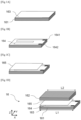
- FIGS 1A to 1D illustrate a measuring core 16 according to a first embodiment, shown in exploded view, and according to the different stages of assembly of the different elements of said measuring core.
- the longitudinal direction X of the measuring core shown is oriented horizontally, although it can be arranged vertically, as shown in Figure 2 , and in particular vertically in the calorimetric sensor as shown in Figures 6A And 6B .
- the assembly of heating resistor and thin layers of insulation forms a heating element, the heating resistor being sandwiched between the two thin layers of insulation.
- the layers constituting the measuring core are parallelepiped in shape, except for the resistor which has a particular shape, described later.
- the layers are stacked on top of each other.
- a sample is an element of matter of known mass, whose nuclear heating is to be measured.
- the material of a sample can be graphite, stainless steel, aluminum or titanium.
- the width and length of a sample vary between a few millimeters to about fifteen millimeters, or even ten millimeters.
- the thickness of a sample is of the order of one to two millimeters, a minimum thickness being required in order to have significant energy deposits. In this embodiment, the two samples have substantially the same dimensions except for their lengths L1, L2.
- the first sample 161 has a length L1 greater than the length L2 of the second sample 162 in order to be able to receive the entire surface of the heating resistor 164 as well as its connections, represented in the form of two pads 1641 and 1642, while the second sample has a reduced length L2 so as to cover the heating resistor with the exception of the connections.
- the first insulating layer 163 also has a length greater than that of the second insulating layer 165.
- Each insulating layer is arranged between the heating resistor and one of the samples, in order to electrically insulate said heating resistor (conductive layer) from the samples.
- Each insulating layer must therefore have sufficient dimensions in the plane to electrically insulate the heating resistor from each sample, but also to be able to be deposited on said sample. In other words, the dimensions in the plane of an insulating layer must also be adapted to those of the sample with which they are directly in contact.
- the thickness of an insulating layer is between approximately 100 nm and a few ⁇ m.
- An insulating layer can be in particular made of silicon oxide, alumina, silicon nitride, magnesium oxide. ⁇ -alumina is particularly interesting because of its very high melting temperature.
- the surface condition of the samples is an important element insofar as it conditions the adhesion of the thin layers of the heating element on said samples.
- the samples Preferably, have a mirror-polished surface condition.
- the samples can undergo a preparation step prior to the deposition of the thin layers, which may consist of cleaning for a few minutes in an ultrasonic bath with acetone, then ethanol and finally distilled water. This preparation of the samples makes it possible to improve the interfaces between the thin layers and the samples and thus improve the physicochemical properties of the assembly.
- the heating resistor comprises a track made of a conductive material shaped, for example, into a serpentine.
- the conductive material may be platinum, a nickel-chromium alloy, or another alloy (such as constantan).
- the thickness of the heating resistor is between approximately a few tens of nm and a few ⁇ m.
- the width of the track is less than or equal to 0.5 mm. All of the characteristics of the track (shape, thickness, width, length) depend on the desired resistance value.
- the heating resistor may be in the form of a spiral, in particular a circular spiral, or any other shape suitable for forming a resistor, in particular meandering and adapted to the shape of the samples.
- the heating resistor and insulating layers together form a heating element which is manufactured at the same time as the measuring core is manufactured.
- the heating element can be manufactured using one of the known microelectronics techniques.
- the heating resistor can be produced in particular using a lift-off photolithography technique coupled with a thin-film deposition technique (in particular sputtering) to obtain the desired shape, for example a serpentine or spiral.
- the insulating thin layers can be deposited using a thin-film deposition technique (in particular sputtering or vacuum thermal evaporation).
- the heating element allows the calorimetric sensor to be calibrated before integration into a nuclear reactor (outside an irradiated environment). In particular, it allows nuclear heating by the Joule effect to be locally simulated.
- the heating element can also allow the calorimetric sensor to be calibrated after integration into a nuclear reactor (in an irradiated environment) and the application of so-called "zero” or "current addition” measurement methods for which it is necessary to provide additional energy to the energy deposited by radiation/matter interaction (measurement methods whose principles are described in the patent FR 2 968 448 but which are adapted in a manner known to those skilled in the art for the measuring core according to the invention).
- the heating element and in particular the heating resistor, can be used to form a temperature sensor, more precisely a resistive temperature probe, to measure the temperature in the hot spot area.
- R T 0 ⁇ T 0 ⁇ L T 0 S T 0
- L is the total length of the heating resistor track and S its section
- ⁇ is the resistivity of the conductive material of the heating resistor, given at the initial temperature T 0 .
- heating resistor to a means of measuring the resistance, preferably by a 4-wire assembly, which is a more precise assembly than a 2 or 3-wire assembly known for measuring a resistance.
- R(T 0 ) can be measured in the same way.
- FIG. 2 represents the measuring core 16 according to the first embodiment of the invention, shown in front view and vertically, as it is generally oriented in the sensor.
- FIG. 3 represents a measuring core 16' according to a second embodiment of the invention shown in front view.
- the measuring core 16' of this second embodiment differs from that of the first embodiment, in that the samples 161', 162' have the same lengths but they have an openwork shape in the upper and lower portions.
- This makes it possible to form four legs per sample (two upper legs 161A', 161B', 162A', 162B' and two lower legs 161C', 161D', 162C', 162D') at the four corners of each sample.
- the upper legs 161A', 161B', 162A', 162B' are wider than the lower legs, so as to accommodate the connection pads 1641' and 1642' of the heating resistor 164'.
- these lower and upper legs can be brought into contact with the casing of the calorimetric sensor, as described later.
- both the upper or lower portions are perforated.
- only an upper portion or a lower portion of one or two samples can be perforated.
- the width and length of a sample vary between a few millimeters to fifteen or even ten millimeters, and the thickness is between one and two millimeters.
- first and second insulating layers (not shown because they are hidden by the samples) have dimensions and shapes adapted to the dimensions of the first and second samples 161', 162' (they are also perforated) and they must always have sufficient dimensions in the plane to insulate the resistance and protect it.
- the dimensions of said thin insulating layers and of said heating resistance are of the same order of magnitude as for the first embodiment.
- the samples and therefore the measuring cores have a parallelepiped shape (openwork or not).
- a parallelepiped shape makes it possible to simplify the assembly of the different layers of the measuring core. This also makes it easier to use certain thin-layer deposition techniques for manufacturing of the heating element, in particular by manufacturing it directly on a sample.
- the 161", 162" samples and thus the 16" measuring core may have a disc shape, as shown in Figure 4
- the longitudinal dimension then corresponds to the diameter of the samples.
- the heating resistor 164" has a circular spiral shape, with two electrical connection pads 1641", 1642" which can be diametrically opposed, as shown (non-limiting).
- the two discs forming the two samples 161", 162" then have different diameters ⁇ 1, ⁇ 2 to accommodate the connection pads of the heating resistor.
- the 163", 165" thin layers are also circular disc-shaped, their diameters being adapted to that of the sample with which they are directly in contact.
- the diameter of a sample varies between a few millimeters to fifteen or even ten millimeters, and the thickness is between one and two millimeters.
- the measuring core can be cylindrical (or even semi-cylindrical) in shape, with the longitudinal direction corresponding to the length of said cylinder, a shape more suited to most measuring channels in nuclear reactors.
- Figure 5 representing a fourth embodiment of a measuring core 17 according to the invention.
- the two samples are of semi-cylindrical shape, that is to say they are cylinders cut in two longitudinally, each half-cylinder then having a flat surface, corresponding to the main plane XY, on which the heating element can be deposited, that is to say the heating resistor sandwiched between the two thin insulating layers.
- the flat surfaces of the half-cylinders are assembled with this heating element which is then sandwiched between the two half-cylinders, so as to form a cylindrical measuring core.
- each semi-cylindrical sample corresponds to the length of said sample, and the latter is a cylinder cut in two along this longitudinal direction.
- the length (L1, L2) of a sample varies between a few millimeters and about fifteen millimeters or even ten millimeters.
- the maximum width, given by the diameter (D1, D2) varies between a few millimeters and about ten millimeters.
- the maximum thickness of a sample given by the radius (D1/2, D2/2) is a few millimeters.
- the first and second samples may have the following respective dimensions: diameter (D1) of 4 mm x length (L1) of 7 mm and diameter (D2) of 4 mm x length (L2) of 4 mm.
- the dimensions of the thin insulating layers (173, 175) and the heating resistor (174) are of the same order of magnitude as for the other embodiments. Since the heating element is arranged on the flat surface XY, it can be rectangular in shape.
- the shape of the measuring core is conditioned by the shape of the samples, as well as by the number of sample(s). For example, if there is only one semi-cylindrical sample, then the shape of the measuring core is also semi-cylindrical.
- the set of layers makes it possible to form a measuring core whose thickness is at most a few millimeters, which makes it possible to reduce the thickness of the calorimetric sensor. Furthermore, the dimensions in the plane of the measuring core (length, width, and/or diameter) are of the order of a centimeter.
- the layers of the heating element are thin layers which are negligible in mass and thickness compared to the samples which are themselves sized to allow radiation-matter interactions and the quantification of nuclear heating, and must therefore have at least a minimal thickness.
- the above embodiments and manufacturing methods apply, except that the second layer of material forming the second sample is not present.
- the electrical heating resistor is sandwiched between the two thin insulating layers in order, on one side, to insulate it from the sample and on the other side, from the protect.
- Both samples are made of the same material. They preferably have the same shapes and dimensions, except for the length or diameter, which may be different. They also have the same surface conditions.
- a thin bonding layer can be provided between the heating resistor and at least one thin insulating layer (the insulating layer on which the resistor is deposited).
- the function of a bonding layer is to allow better bonding of the heating resistor to the insulating layer.
- the thickness of a bonding layer must be very low (a few nanometers) so as not to disturb the assembly. This bonding layer must have the same shape as the heating element.
- another bonding layer can be deposited between the sample(s) and one or more thin insulating layers, for better bonding of one or more thin insulating layers to the sample(s).
- a bonding layer can be, for example, a titanium layer or a tantalum layer.
- At least one functional layer can be added to the measurement core.
- This can be a layer of boron, cadmium, silicon carbide (SiC) and/or lithium.
- a functional layer has smaller dimensions than the samples, and can be applied to a sample (for example on its outer face). It can, for example, have a thickness of the same order as the other thin layers.
- Such a functional layer can make it possible to: generate selective specific interactions, and/or convert particles/radiation, and/or amplify nuclear heating.
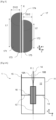
- FIGS. 6A (longitudinal sectional view) and 6B (3D view) illustrate a calorimetric sensor according to a first embodiment. This is shown with a measuring core configured according to the first embodiment, but it could include a measuring core according to one of the other embodiments or any other measuring core falling within the scope of the invention.
- the measuring core is integrated into a gas-containing envelope, and is kept centered in said envelope by several spacers which also allow heat to be transferred between the measuring core and the envelope.
- the waterproof envelope allows the various elements to be contained and protected. Furthermore, the envelope is designed to be in direct contact with a heat transfer fluid in order to evacuate thermal energy.
- the casing can be made of aluminum, stainless steel or titanium.
- the envelope shown is parallelepiped in shape.
- the dimensions of the envelope are typically a few centimeters, for example a length of about three centimeters, a width of about two centimeters, and a depth of about one centimeter.
- the dimensions could, however, be reduced and more generally vary between a few millimeters and a few centimeters (typically less than or equal to three centimeters).
- the thickness of the walls of the envelope is, for example, 1 ⁇ 2 millimeter.
- the casing may be cylindrical, a shape more suitable for most measurement channels in nuclear reactors.
- the measuring core is preferably cylindrical or semi-cylindrical, but a parallelepiped shape could be suitable.
- a cylindrical casing may have a tapered end to improve the flow of the heat transfer fluid around the calorimetric sensor.
- the sensitivity of the sensor can be adjusted by choosing the nature of the gas according to its thermal conductivity and therefore by playing on the thermal resistance of the gas blade. It can also help to avoid oxidation in the sensor.
- the gas can be helium, nitrogen, argon, or xenon.
- the gas can be a few tens of mbars overpressure compared to atmospheric pressure.
- the first temperature sensor is located as close as possible to the center of the measuring core and allows a temperature to be measured at a so-called “hot” point.
- the second temperature sensor is placed on (or integrated into) the casing and allows a temperature to be measured at a so-called “cold” point. The temperature measurements at the cold and hot points allow nuclear heating to be determined.
- the first sensor may be a thermocouple, for example of type K or N, the diameter of which is preferably between 0.1 mm and 0.5 mm.
- the materials of the thermocouples may be: Chromel (Ni-Cr), Alumel (Ni-Al), Ni-crosil (Ni-Cr-Si), Nisil (Ni-Si).
- the first sensor is as close as possible to the heating element, and it is preferably geometrically aligned with respect to the center of the heating element.
- the first sensor may be formed by the heating element which then forms a resistive temperature probe.
- the second sensor may be a thermocouple, for example of type K or N, with a diameter preferably between 0.1 mm and 0.5 mm.
- the thermocouple materials may be: Chromel (Ni-Cr), Alumel (Ni-Al), Ni-crosil (Ni-Cr-Si), Nisil (Ni-Si).
- the second sensor may be geometrically aligned with respect to the center of the heating element, with a temperature measurement at the envelope, as shown. This may be at the internal face or at the external face of the envelope wall.
- Each temperature sensor is wired using a connector (not shown) to transfer the measurement from the measurement core to the data acquisition unit.
- Temperature sensors can advantageously be micro-thermocouples, either wire micro-thermocouples or thin-film micro-thermocouples.
- the diameter (wire micro-thermocouple) or thickness (film micro-thermocouple) of such a sensor is of the order of a few micrometers at the measurement point. Connections with diameters similar to those of conventional thermocouples are also necessary to transfer the measurement from the measuring core to the data acquisition unit.
- the small size of micro-thermocouples has the advantage of less disruption to the measurement due to their lower intrusiveness, especially in the case where the dimensions of the measuring core are comparable to those of the temperature sensors. They are positioned in the same position as conventional thermocouples: close to the heating element and close to the casing.
- the heating resistor is wired using wires (between two and four wires) 19A and 19B which pass through the casing 11 and are then connected to connectors for connection to power supplies and to an acquisition center.
- the spacers can be in the form of cylindrical rods (with a diameter of 1 millimeter for example) and/or parallelepipeds.
- the spacers are made of a material identical to that of the samples, for example aluminum, stainless steel or titanium. Beyond their function of holding, positioning and/or centering, the spacers are also configured to transfer heat between the measuring core and the envelope. Thus, they can be of dimensions chosen to form a given thermal resistance and therefore be a parameter for adjusting the sensitivity of the sensor. In addition, spacers are sought whose thickness and dimensions allow for the addition of no parasitic mass.
- All or part of the spacers may be formed by tabs at the four corners of the samples by an openwork shape of the samples as illustrated in Figure 3 and in the Figure 7 described below, and/or by pointed shapes provided inside the envelope.
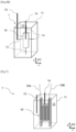
- FIG. 7 represents a calorimetric sensor according to a second embodiment in which the measuring core has an openwork shape, like the measuring core 16' of the Figure 3 .
- the calorimetric sensor 1' shown does not include spacers, the measuring core 16' being held in the casing 11 by the legs of the two perforated samples (eight legs in total).
- the heat is mainly conducted longitudinally. Spacers can be added to transmit the heat transversely/radially and/or to center the measuring core transversely/radially.
Landscapes
- Physics & Mathematics (AREA)
- Engineering & Computer Science (AREA)
- General Physics & Mathematics (AREA)
- Chemical & Material Sciences (AREA)
- Combustion & Propulsion (AREA)
- Crystallography & Structural Chemistry (AREA)
- High Energy & Nuclear Physics (AREA)
- General Engineering & Computer Science (AREA)
- Plasma & Fusion (AREA)
- Health & Medical Sciences (AREA)
- Life Sciences & Earth Sciences (AREA)
- Analytical Chemistry (AREA)
- Biochemistry (AREA)
- General Health & Medical Sciences (AREA)
- Immunology (AREA)
- Pathology (AREA)
- Investigating Or Analyzing Materials Using Thermal Means (AREA)
Claims (23)
- Messkern (16, 16', 16'', 17) zur Messung der Kernerwärmung in einem Kernreaktor, wobei sich der Kern in einer Längsrichtung (X) erstreckt und eine Hauptebene (XY) aufweist, wobei der Messkern mindestens Folgendes umfasst:- eine erste Materialschicht, die eine erste Probe (161, 161', 161", 171) bildet;- eine erste dünne Schicht aus elektrischem Isoliermaterial (163, 163'', 173), die auf der ersten Probe angeordnet ist;- eine dünne leitfähige Schicht, die einen elektrischen Heizwiderstand bildet (164, 164', 164'', 174), der auf der ersten elektrischen Isolierschicht angeordnet ist;- eine zweite dünne Schicht aus elektrischem Isoliermaterial (165, 165", 175), die auf dem elektrischen Heizwiderstand angeordnet ist;wobei die erste dünne Schicht aus Isoliermaterial Abmessungen in der Hauptebene aufweist, die an diejenigen der ersten Probe angepasst sind;wobei die dünnen Schichten aus elektrischem Isoliermaterial so konfiguriert sind, dass sie den Heizwiderstand von der Probe isolieren und den Heizwiderstand schützen, undwobei die erste Probe vorzugsweise Abmessungen von kleiner oder gleich rund fünfzehn oder sogar rund zehn Millimetern in der Hauptebene und/oder eine Dicke von kleiner oder gleich 10 Millimetern, noch bevorzugter kleiner oder gleich 2 Millimetern, aufweist.
- Messkern (16, 16', 16'', 17) nach Anspruch 1, ferner Folgendes umfassend:- eine zweite Materialschicht, die eine zweite Probe (162, 162', 162'', 172) bildet; wobei sich die zweite dünne Schicht aus elektrischem Isoliermaterial zwischen dem Heizwiderstand und der zweiten Probe befindet;wobei die zweite dünne Schicht aus Isoliermaterial Abmessungen in der Hauptebene aufweist, die an diejenigen der zweiten Probe angepasst sind;wobei die zweite Schicht aus elektrischem Isoliermaterial so konfiguriert ist, dass sie den Heizwiderstand von der zweiten Probe isoliert;wobei die zweite Probe vorzugsweise Abmessungen von kleiner oder gleich rund fünfzehn oder sogar rund zehn Millimetern in der Hauptebene und/oder eine Dicke von kleiner oder gleich 10 Millimetern, noch bevorzugter kleiner oder gleich 2 Millimetern, aufweist.
- Messkern (16, 16'', 17) nach Anspruch 2, wobei die erste Probe (161, 161", 171) eine Länge (L1) beziehungsweise einen Durchmesser (Φ1) aufweist, die beziehungsweise der größer ist als die Länge (L2) beziehungsweise der Durchmesser (Φ2) der zweiten Probe (162, 162", 172).
- Messkern (16, 16', 16", 17) nach einem der vorhergehenden Ansprüche, wobei der Heizwiderstand (164, 164', 164'', 174) eine Bahn aus einem leitfähigen Material umfasst, die in Form einer Schlange, einer Spirale oder eines Mäanders ausgebildet ist.
- Messkern (16, 16', 16'', 17) nach einem der vorhergehenden Ansprüche, wobei der Heizwiderstand (164, 164', 164'', 174) aus Platin, einer Nickel-Chrom-Legierung oder Konstantan besteht.
- Messkern (16, 16', 16'', 17) nach einem der vorhergehenden Ansprüche, wobei die dünnen Schichten aus elektrischem Isoliermaterial aus Siliziumoxid, Aluminiumoxid, Siliziumnitrid oder Magnesiumoxid bestehen.
- Messkern (16, 16', 16'', 17) nach einem der vorhergehenden Ansprüche, wobei die Probe(n) aus Graphit, Edelstahl, Aluminium oder Titan besteht beziehungsweise bestehen.
- Messkern (16, 16', 16", 17) nach einem der vorhergehenden Ansprüche, wobei die Probe(n) eine Oberflächenbeschaffenheit aufweist beziehungsweise aufweisen, die für die Ablagerung mindestens einer dünnen Schicht aus elektrischem Isoliermaterial durch eine Dünnschichtablagerungstechnik angepasst ist, beispielsweise eine spiegelpolierte Oberflächenbeschaffenheit.
- Messkern nach einem der vorhergehenden Ansprüche, ferner umfassend mindestens eine Haftschicht zwischen dem Heizwiderstand und mindestens einer dünnen Schicht aus elektrischem Isoliermaterial und/oder zwischen mindestens einer Probe und mindestens einer dünnen Schicht aus elektrischem Isoliermaterial umfasst.
- Messkern nach einem der vorhergehenden Ansprüche, ferner umfassend mindestens eine Funktionsschicht, die eine Schicht aus Bor, Cadmium, Siliziumkarbid (SiC) und/oder Lithium sein kann, wobei die Funktionsschicht auf der Außenseite mindestens einer Probe abgelagert sein kann.
- Messkern (16, 16') nach einem der Ansprüche 1 bis 10, wobei die erste Probe (161, 161') und gegebenenfalls die zweite Probe (162, 162') quaderförmig sind, wodurch sie einen quaderförmigen Kern bilden.
- Messkern (17) nach einem der Ansprüche 1 bis 10, wobei die erste Probe (171), und gegebenenfalls die zweite Probe (172), eine halbzylindrische Form aufweisen, wodurch sie einen halbzylindrischen oder zylindrischen Kern bilden, wobei sich die Zylinderlänge in Längsrichtung (X) erstreckt.
- Messkern (16'') nach einem der Ansprüche 1 bis 10, wobei die erste Probe (161''), und gegebenenfalls die zweite Probe (162''), eine Scheibenform aufweisen, wobei sich der Scheibendurchmesser in Längsrichtung (X) erstreckt.
- Messkern (16') gemäß einem der vorhergehenden Ansprüche, wobei mindestens eine Probe (161', 162') an mindestens einem oberen und/oder unteren Abschnitt durchbrochen ist, sodass mindestens zwei obere Laschen (161A' 161B', 162A', 162B') und/oder mindestens zwei unteren Laschen (161C', 161D', 162C', 162D') gebildet werden.
- Messkern (16') nach Anspruch 14, wobei die oberen Laschen so bemessen sind, dass sie die Verbindungselemente (1641', 1642') des Heizwiderstands (164') aufnehmen können, wobei die oberen Laschen beispielsweise eine größere Breite als die unteren Laschen aufweisen.
- Messkern (16, 16', 16'', 17) nach einem der vorhergehenden Ansprüche, wobei der Heizwiderstand so konfiguriert ist, dass er einen Widerstandstemperaturfühler bildet, um die Temperatur in einem Bereich zu messen, der eine heiße Stelle zur Temperaturmessung umfasst, wobei der Heizwiderstand dann mit einem Mittel zur Messung des Widerstands verbunden ist, vorzugsweise durch eine Vierleiter-Schaltung.
- Kalorimetrischer Sensor (1, 1') zur Messung der Kernerwärmung in einem Kernreaktor, wobei der Sensor Folgendes umfasst:- eine fluiddichte Außenhülle (11)- ein in der Außenhülle enthaltenes Gas (12)- einen Messkern (16, 16', 16'', 17), der nach einem der Ansprüche 1 bis 16 ausgewählt ist, wobei der Kern in der äußeren Hülle angeordnet ist;- Verbindungsmittel (13, 161A', 161B', 161C', 161D', 162A', 162B', 162C', 162D'), die in der Lage sind, den Messkern in der äußeren Hülle zu halten und die Wärme zwischen dem Kern und der Hülle zu übertragen;- Temperaturmessmittel (14, 164, 164', 164'', 174, 15), umfassend ein erstes Temperaturmessmittel (14, 164, 164', 164'', 174), das in der Lage ist, die Temperatur an einem heißen Punkt zu messen, vorzugsweise so nahe wie möglich am Heizelement des Messkerns, und ein zweites Temperaturmessmittel (15), das in der Lage ist, die Temperatur an einem kalten Punkt zu messen, vorzugsweise an einer Wand der Hülle (11).
- Kalorimetrischer Sensor (1, 1') nach Anspruch 17, wobei die Temperaturmessmittel (14, 15) mindestens ein Thermoelement, vorzugsweise ein drahtgebundenes Mikrothermoelement oder ein Dünnschicht-Mikrothermoelement, umfassen.
- Kalorimetrischer Sensor (1, 1') nach Anspruch 17 oder Anspruch 18, wobei der Messkern nach Anspruch 16 gewählt ist, wobei das erste Temperaturmessmittel durch den Heizwiderstand (164, 164', 164", 174) gebildet wird.
- Kalorimetrischer Sensor (1, 1') nach einem der Ansprüche 17 bis 19, wobei die Verbindungsmittel Abstandhalter (13) umfassen, die unterschiedliche Formen und Materialien aufweisen können.
- Kalorimetrischer Sensor (1, 1') nach einem der Ansprüche 17 bis 20, wobei mindestens eine Probe (161', 162') an mindestens einem oberen und/oder unteren Abschnitt durchbrochen ist, sodass mindestens zwei obere Laschen (161A', 161B', 162A', 162B') und/oder mindestens zwei unteren Laschen (161C', 161D', 162C', 162D') gebildet werden, wobei die Verbindungsmittel ganz oder teilweise durch die Laschen gebildet werden.
- Kalorimetrischer Sensor (1, 1') nach einem der Ansprüche 17 bis 21, wobei die Hülle (11) aus Aluminium, Edelstahl oder Titan besteht.
- Kalorimetrischer Sensor (1, 1') nach einem der Ansprüche 17 bis 22, wobei die Hülle (11) eine quaderförmige oder zylindrische Form aufweist, die wahlweise ein konisches Ende aufweist, um den Fluss des Wärmeträgerfluids um den kalorimetrischen Sensor herum zu verbessern.
Applications Claiming Priority (1)
| Application Number | Priority Date | Filing Date | Title |
|---|---|---|---|
| FR2013804A FR3118198B1 (fr) | 2020-12-21 | 2020-12-21 | Noyau de mesure pour la mesure d'échauffement nucléaire en réacteur nucléaire et capteur calorimétrique intégrant un tel noyau de mesure |
Publications (3)
| Publication Number | Publication Date |
|---|---|
| EP4016549A1 EP4016549A1 (de) | 2022-06-22 |
| EP4016549C0 EP4016549C0 (de) | 2025-05-28 |
| EP4016549B1 true EP4016549B1 (de) | 2025-05-28 |
Family
ID=76522985
Family Applications (1)
| Application Number | Title | Priority Date | Filing Date |
|---|---|---|---|
| EP21212899.5A Active EP4016549B1 (de) | 2020-12-21 | 2021-12-07 | Messkern für die messung der nuklearen erwärmung in einem kernreaktor und kalorimetrischer sensor mit einem solchen messkern |
Country Status (4)
| Country | Link |
|---|---|
| US (1) | US11971312B2 (de) |
| EP (1) | EP4016549B1 (de) |
| CN (1) | CN114646659A (de) |
| FR (1) | FR3118198B1 (de) |
Family Cites Families (9)
| Publication number | Priority date | Publication date | Assignee | Title |
|---|---|---|---|---|
| US7473030B2 (en) * | 2002-04-01 | 2009-01-06 | Palo Alto Research Center Incorporated | Thermal sensing |
| US7106167B2 (en) * | 2002-06-28 | 2006-09-12 | Heetronix | Stable high temperature sensor system with tungsten on AlN |
| US8637138B2 (en) * | 2005-12-27 | 2014-01-28 | Palo Alto Research Center Incorporated | Layered structures on thin substrates |
| ATE553361T1 (de) * | 2006-10-23 | 2012-04-15 | Ust Umweltsensortechnik Gmbh | Hochtemperatursensor und verfahren zu dessen überprüfung |
| FR2968448B1 (fr) | 2010-12-03 | 2013-01-04 | Commissariat Energie Atomique | Cellule calorimetrique mobile pour mesure d'echauffement en c?ur de reacteur nucleaire |
| FR3034867B1 (fr) | 2015-04-10 | 2020-01-31 | Commissariat A L'energie Atomique Et Aux Energies Alternatives | Eprouvette pour mesure d'echauffement nucleaire dans un reacteur nucleaire, et cellule calorimetrique comprenant au moins une telle eprouvette |
| US20170358374A1 (en) * | 2016-06-09 | 2017-12-14 | Ge-Hitachi Nuclear Energy Americas Llc | Nuclear reactor fluid thermal monitoring array |
| DE102016119340A1 (de) * | 2016-10-11 | 2018-04-12 | Heraeus Sensor Technology Gmbh | Verfahren zur Herstellung eines Sensors, Sensor und Verwendung eines Sensors |
| KR101879343B1 (ko) * | 2017-02-06 | 2018-08-17 | 광주과학기술원 | 바이오 샘플용 다목적 마이크로 열량계 및 이의 제조방법 |
-
2020
- 2020-12-21 FR FR2013804A patent/FR3118198B1/fr active Active
-
2021
- 2021-12-07 EP EP21212899.5A patent/EP4016549B1/de active Active
- 2021-12-13 US US17/549,762 patent/US11971312B2/en active Active
- 2021-12-20 CN CN202111560059.2A patent/CN114646659A/zh active Pending
Also Published As
| Publication number | Publication date |
|---|---|
| EP4016549C0 (de) | 2025-05-28 |
| US11971312B2 (en) | 2024-04-30 |
| FR3118198A1 (fr) | 2022-06-24 |
| EP4016549A1 (de) | 2022-06-22 |
| CN114646659A (zh) | 2022-06-21 |
| FR3118198B1 (fr) | 2023-08-18 |
| US20220196488A1 (en) | 2022-06-23 |
Similar Documents
| Publication | Publication Date | Title |
|---|---|---|
| EP3280985B1 (de) | Kalorimetrische zelle zur messung der nuklearen aufheizung in einem kernreaktor | |
| EP2898318B1 (de) | Wärmeflusssensor und gas sensor mit mindestens einem solchen sensor | |
| EP0749007B1 (de) | Bolometrische Detektorvorrichtung für Millimeter- und Submillimeterwellen und Herstellungsverfahren für diese Vorrichtung | |
| EP2340422A1 (de) | Bolometrischer detektor zum detektieren von elektromagnetischen welllen | |
| EP2447688A1 (de) | Detektor für elektromagnetische Strahlung | |
| EP2711698B1 (de) | Wärmeflusssensor mit einer durch Nanodrähte abgestützten Membran | |
| EP2908109A1 (de) | Bolometrischer Detektor mit MIM-Struktur, der ein Thermometerelement umfasst | |
| EP2908122A1 (de) | Gaskonzentrationssensor mit Hängestruktur | |
| EP3214576A1 (de) | Verkapselte wärmtemustersensor mit bolometers | |
| EP1880176B1 (de) | Thermischer detektor für elektromagnetische strahlung in einer die detektoren verwendenden infrarot-detektionseinrichtung | |
| EP4016549B1 (de) | Messkern für die messung der nuklearen erwärmung in einem kernreaktor und kalorimetrischer sensor mit einem solchen messkern | |
| FR2968448A1 (fr) | Cellule calorimetrique mobile pour mesure d'echauffement en cœur de reacteur nucleaire | |
| WO2007034048A1 (fr) | Microcapteur de flux thermique sur substrat conducteur avec caisson(s) poreux | |
| EP1616159B1 (de) | Thermischer detektor mit wabenförmiger struktur für elektromagnetische strahlung | |
| FR2781931A1 (fr) | Thermopiles a thermojonctions du type distribuees, fluxmetres thermiques radiatif et conductif mettant en oeuvre ces thermopiles, ainsi que leurs procedes de fabrication | |
| EP3667309B1 (de) | Wärmeflusssensor mit heizdraht | |
| EP0026126A1 (de) | Verfahren zum Messen eines ständigen Neutronenflusses und Apparat zur Durchführung dieses Verfahrens | |
| FR2704948A1 (fr) | Cellule d'analyse thermique différentielle, dispositif et procédé utilisant une telle cellule. | |
| FR3132765A1 (fr) | Capteurs pour systèmes de mesure de flux thermique à inertie | |
| FR2704979A1 (fr) | Procédé de réalisation d'un fluxmètre thermique et fluxmètre thermique obtenu selon ce procédé. | |
| WO2011023916A1 (fr) | Capteur microsystème de mesure ou de détection d'encrassement | |
| EP3663752A1 (de) | Thermischer flusssensor mit heizbaren nanodrähten | |
| WO2024028209A1 (fr) | Détecteur thermique de rayonnement | |
| FR3002041A1 (fr) | Dispositif et procede de mesure de la conductivite thermique d'un produit humide en amas. | |
| FR2458802A1 (fr) | Procede et dispositif de mesure de flux de chaleur |
Legal Events
| Date | Code | Title | Description |
|---|---|---|---|
| PUAI | Public reference made under article 153(3) epc to a published international application that has entered the european phase |
Free format text: ORIGINAL CODE: 0009012 |
|
| STAA | Information on the status of an ep patent application or granted ep patent |
Free format text: STATUS: REQUEST FOR EXAMINATION WAS MADE |
|
| 17P | Request for examination filed |
Effective date: 20211207 |
|
| AK | Designated contracting states |
Kind code of ref document: A1 Designated state(s): AL AT BE BG CH CY CZ DE DK EE ES FI FR GB GR HR HU IE IS IT LI LT LU LV MC MK MT NL NO PL PT RO RS SE SI SK SM TR |
|
| RAP3 | Party data changed (applicant data changed or rights of an application transferred) |
Owner name: CENTRE NATIONAL DE LA RECHERCHE SCIENTIFIQUE Owner name: UNIVERSITE D'AIX MARSEILLE Owner name: COMMISSARIAT A L'ENERGIE ATOMIQUE ET AUX ENERGIESALTERNATIVES |
|
| GRAP | Despatch of communication of intention to grant a patent |
Free format text: ORIGINAL CODE: EPIDOSNIGR1 |
|
| STAA | Information on the status of an ep patent application or granted ep patent |
Free format text: STATUS: GRANT OF PATENT IS INTENDED |
|
| INTG | Intention to grant announced |
Effective date: 20250121 |
|
| GRAS | Grant fee paid |
Free format text: ORIGINAL CODE: EPIDOSNIGR3 |
|
| GRAA | (expected) grant |
Free format text: ORIGINAL CODE: 0009210 |
|
| STAA | Information on the status of an ep patent application or granted ep patent |
Free format text: STATUS: THE PATENT HAS BEEN GRANTED |
|
| AK | Designated contracting states |
Kind code of ref document: B1 Designated state(s): AL AT BE BG CH CY CZ DE DK EE ES FI FR GB GR HR HU IE IS IT LI LT LU LV MC MK MT NL NO PL PT RO RS SE SI SK SM TR |
|
| REG | Reference to a national code |
Ref country code: GB Ref legal event code: FG4D Free format text: NOT ENGLISH |
|
| REG | Reference to a national code |
Ref country code: CH Ref legal event code: EP |
|
| REG | Reference to a national code |
Ref country code: IE Ref legal event code: FG4D Free format text: LANGUAGE OF EP DOCUMENT: FRENCH Ref country code: DE Ref legal event code: R096 Ref document number: 602021031391 Country of ref document: DE |
|
| U01 | Request for unitary effect filed |
Effective date: 20250604 |
|
| U07 | Unitary effect registered |
Designated state(s): AT BE BG DE DK EE FI FR IT LT LU LV MT NL PT RO SE SI Effective date: 20250612 |
|
| PG25 | Lapsed in a contracting state [announced via postgrant information from national office to epo] |
Ref country code: ES Free format text: LAPSE BECAUSE OF FAILURE TO SUBMIT A TRANSLATION OF THE DESCRIPTION OR TO PAY THE FEE WITHIN THE PRESCRIBED TIME-LIMIT Effective date: 20250528 |
|
| PG25 | Lapsed in a contracting state [announced via postgrant information from national office to epo] |
Ref country code: GR Free format text: LAPSE BECAUSE OF FAILURE TO SUBMIT A TRANSLATION OF THE DESCRIPTION OR TO PAY THE FEE WITHIN THE PRESCRIBED TIME-LIMIT Effective date: 20250829 Ref country code: NO Free format text: LAPSE BECAUSE OF FAILURE TO SUBMIT A TRANSLATION OF THE DESCRIPTION OR TO PAY THE FEE WITHIN THE PRESCRIBED TIME-LIMIT Effective date: 20250828 |
|
| PG25 | Lapsed in a contracting state [announced via postgrant information from national office to epo] |
Ref country code: PL Free format text: LAPSE BECAUSE OF FAILURE TO SUBMIT A TRANSLATION OF THE DESCRIPTION OR TO PAY THE FEE WITHIN THE PRESCRIBED TIME-LIMIT Effective date: 20250528 |
|
| PG25 | Lapsed in a contracting state [announced via postgrant information from national office to epo] |
Ref country code: HR Free format text: LAPSE BECAUSE OF FAILURE TO SUBMIT A TRANSLATION OF THE DESCRIPTION OR TO PAY THE FEE WITHIN THE PRESCRIBED TIME-LIMIT Effective date: 20250528 |
|
| PG25 | Lapsed in a contracting state [announced via postgrant information from national office to epo] |
Ref country code: RS Free format text: LAPSE BECAUSE OF FAILURE TO SUBMIT A TRANSLATION OF THE DESCRIPTION OR TO PAY THE FEE WITHIN THE PRESCRIBED TIME-LIMIT Effective date: 20250828 |
|
| PG25 | Lapsed in a contracting state [announced via postgrant information from national office to epo] |
Ref country code: IS Free format text: LAPSE BECAUSE OF FAILURE TO SUBMIT A TRANSLATION OF THE DESCRIPTION OR TO PAY THE FEE WITHIN THE PRESCRIBED TIME-LIMIT Effective date: 20250928 |
|
| PGFP | Annual fee paid to national office [announced via postgrant information from national office to epo] |
Ref country code: GB Payment date: 20251229 Year of fee payment: 5 |
|
| PG25 | Lapsed in a contracting state [announced via postgrant information from national office to epo] |
Ref country code: SM Free format text: LAPSE BECAUSE OF FAILURE TO SUBMIT A TRANSLATION OF THE DESCRIPTION OR TO PAY THE FEE WITHIN THE PRESCRIBED TIME-LIMIT Effective date: 20250528 |
|
| PG25 | Lapsed in a contracting state [announced via postgrant information from national office to epo] |
Ref country code: CZ Free format text: LAPSE BECAUSE OF FAILURE TO SUBMIT A TRANSLATION OF THE DESCRIPTION OR TO PAY THE FEE WITHIN THE PRESCRIBED TIME-LIMIT Effective date: 20250528 |
|
| U20 | Renewal fee for the european patent with unitary effect paid |
Year of fee payment: 5 Effective date: 20251217 |
|
| PG25 | Lapsed in a contracting state [announced via postgrant information from national office to epo] |
Ref country code: SK Free format text: LAPSE BECAUSE OF FAILURE TO SUBMIT A TRANSLATION OF THE DESCRIPTION OR TO PAY THE FEE WITHIN THE PRESCRIBED TIME-LIMIT Effective date: 20250528 |