EP4016535B1 - Koppelbare vorrichtungen und systeme und verfahren zur bereitstellung einer unterstützten kopplung von vorrichtungen an bestimmte orte - Google Patents
Koppelbare vorrichtungen und systeme und verfahren zur bereitstellung einer unterstützten kopplung von vorrichtungen an bestimmte orte Download PDFInfo
- Publication number
- EP4016535B1 EP4016535B1 EP21214707.8A EP21214707A EP4016535B1 EP 4016535 B1 EP4016535 B1 EP 4016535B1 EP 21214707 A EP21214707 A EP 21214707A EP 4016535 B1 EP4016535 B1 EP 4016535B1
- Authority
- EP
- European Patent Office
- Prior art keywords
- medical device
- wireless
- control
- control device
- data
- Prior art date
- Legal status (The legal status is an assumption and is not a legal conclusion. Google has not performed a legal analysis and makes no representation as to the accuracy of the status listed.)
- Active
Links
Images


Classifications
-
- H—ELECTRICITY
- H04—ELECTRIC COMMUNICATION TECHNIQUE
- H04W—WIRELESS COMMUNICATION NETWORKS
- H04W8/00—Network data management
- H04W8/005—Discovery of network devices, e.g. terminals
-
- H—ELECTRICITY
- H04—ELECTRIC COMMUNICATION TECHNIQUE
- H04W—WIRELESS COMMUNICATION NETWORKS
- H04W12/00—Security arrangements; Authentication; Protecting privacy or anonymity
- H04W12/50—Secure pairing of devices
-
- H—ELECTRICITY
- H04—ELECTRIC COMMUNICATION TECHNIQUE
- H04W—WIRELESS COMMUNICATION NETWORKS
- H04W4/00—Services specially adapted for wireless communication networks; Facilities therefor
- H04W4/70—Services for machine-to-machine communication [M2M] or machine type communication [MTC]
-
- A—HUMAN NECESSITIES
- A61—MEDICAL OR VETERINARY SCIENCE; HYGIENE
- A61M—DEVICES FOR INTRODUCING MEDIA INTO, OR ONTO, THE BODY; DEVICES FOR TRANSDUCING BODY MEDIA OR FOR TAKING MEDIA FROM THE BODY; DEVICES FOR PRODUCING OR ENDING SLEEP OR STUPOR
- A61M5/00—Devices for bringing media into the body in a subcutaneous, intra-vascular or intramuscular way; Accessories therefor, e.g. filling or cleaning devices, arm-rests
- A61M5/14—Infusion devices, e.g. infusing by gravity; Blood infusion; Accessories therefor
- A61M5/142—Pressure infusion, e.g. using pumps
-
- G—PHYSICS
- G16—INFORMATION AND COMMUNICATION TECHNOLOGY [ICT] SPECIALLY ADAPTED FOR SPECIFIC APPLICATION FIELDS
- G16H—HEALTHCARE INFORMATICS, i.e. INFORMATION AND COMMUNICATION TECHNOLOGY [ICT] SPECIALLY ADAPTED FOR THE HANDLING OR PROCESSING OF MEDICAL OR HEALTHCARE DATA
- G16H40/00—ICT specially adapted for the management or administration of healthcare resources or facilities; ICT specially adapted for the management or operation of medical equipment or devices
- G16H40/20—ICT specially adapted for the management or administration of healthcare resources or facilities; ICT specially adapted for the management or operation of medical equipment or devices for the management or administration of healthcare resources or facilities, e.g. managing hospital staff or surgery rooms
-
- G—PHYSICS
- G16—INFORMATION AND COMMUNICATION TECHNOLOGY [ICT] SPECIALLY ADAPTED FOR SPECIFIC APPLICATION FIELDS
- G16H—HEALTHCARE INFORMATICS, i.e. INFORMATION AND COMMUNICATION TECHNOLOGY [ICT] SPECIALLY ADAPTED FOR THE HANDLING OR PROCESSING OF MEDICAL OR HEALTHCARE DATA
- G16H40/00—ICT specially adapted for the management or administration of healthcare resources or facilities; ICT specially adapted for the management or operation of medical equipment or devices
- G16H40/60—ICT specially adapted for the management or administration of healthcare resources or facilities; ICT specially adapted for the management or operation of medical equipment or devices for the operation of medical equipment or devices
- G16H40/63—ICT specially adapted for the management or administration of healthcare resources or facilities; ICT specially adapted for the management or operation of medical equipment or devices for the operation of medical equipment or devices for local operation
-
- G—PHYSICS
- G16—INFORMATION AND COMMUNICATION TECHNOLOGY [ICT] SPECIALLY ADAPTED FOR SPECIFIC APPLICATION FIELDS
- G16H—HEALTHCARE INFORMATICS, i.e. INFORMATION AND COMMUNICATION TECHNOLOGY [ICT] SPECIALLY ADAPTED FOR THE HANDLING OR PROCESSING OF MEDICAL OR HEALTHCARE DATA
- G16H40/00—ICT specially adapted for the management or administration of healthcare resources or facilities; ICT specially adapted for the management or operation of medical equipment or devices
- G16H40/60—ICT specially adapted for the management or administration of healthcare resources or facilities; ICT specially adapted for the management or operation of medical equipment or devices for the operation of medical equipment or devices
- G16H40/67—ICT specially adapted for the management or administration of healthcare resources or facilities; ICT specially adapted for the management or operation of medical equipment or devices for the operation of medical equipment or devices for remote operation
-
- H—ELECTRICITY
- H04—ELECTRIC COMMUNICATION TECHNIQUE
- H04L—TRANSMISSION OF DIGITAL INFORMATION, e.g. TELEGRAPHIC COMMUNICATION
- H04L67/00—Network arrangements or protocols for supporting network services or applications
- H04L67/01—Protocols
- H04L67/12—Protocols specially adapted for proprietary or special-purpose networking environments, e.g. medical networks, sensor networks, networks in vehicles or remote metering networks
-
- H—ELECTRICITY
- H04—ELECTRIC COMMUNICATION TECHNIQUE
- H04W—WIRELESS COMMUNICATION NETWORKS
- H04W48/00—Access restriction; Network selection; Access point selection
- H04W48/08—Access restriction or access information delivery, e.g. discovery data delivery
- H04W48/10—Access restriction or access information delivery, e.g. discovery data delivery using broadcasted information
-
- H—ELECTRICITY
- H04—ELECTRIC COMMUNICATION TECHNIQUE
- H04W—WIRELESS COMMUNICATION NETWORKS
- H04W76/00—Connection management
- H04W76/10—Connection setup
- H04W76/14—Direct-mode setup
-
- H—ELECTRICITY
- H04—ELECTRIC COMMUNICATION TECHNIQUE
- H04W—WIRELESS COMMUNICATION NETWORKS
- H04W76/00—Connection management
- H04W76/30—Connection release
-
- A—HUMAN NECESSITIES
- A61—MEDICAL OR VETERINARY SCIENCE; HYGIENE
- A61M—DEVICES FOR INTRODUCING MEDIA INTO, OR ONTO, THE BODY; DEVICES FOR TRANSDUCING BODY MEDIA OR FOR TAKING MEDIA FROM THE BODY; DEVICES FOR PRODUCING OR ENDING SLEEP OR STUPOR
- A61M2205/00—General characteristics of the apparatus
- A61M2205/35—Communication
- A61M2205/3546—Range
- A61M2205/3553—Range remote, e.g. between patient's home and doctor's office
-
- A—HUMAN NECESSITIES
- A61—MEDICAL OR VETERINARY SCIENCE; HYGIENE
- A61M—DEVICES FOR INTRODUCING MEDIA INTO, OR ONTO, THE BODY; DEVICES FOR TRANSDUCING BODY MEDIA OR FOR TAKING MEDIA FROM THE BODY; DEVICES FOR PRODUCING OR ENDING SLEEP OR STUPOR
- A61M2205/00—General characteristics of the apparatus
- A61M2205/35—Communication
- A61M2205/3546—Range
- A61M2205/3561—Range local, e.g. within room or hospital
-
- A—HUMAN NECESSITIES
- A61—MEDICAL OR VETERINARY SCIENCE; HYGIENE
- A61M—DEVICES FOR INTRODUCING MEDIA INTO, OR ONTO, THE BODY; DEVICES FOR TRANSDUCING BODY MEDIA OR FOR TAKING MEDIA FROM THE BODY; DEVICES FOR PRODUCING OR ENDING SLEEP OR STUPOR
- A61M2205/00—General characteristics of the apparatus
- A61M2205/35—Communication
- A61M2205/3576—Communication with non implanted data transmission devices, e.g. using external transmitter or receiver
- A61M2205/3584—Communication with non implanted data transmission devices, e.g. using external transmitter or receiver using modem, internet or bluetooth
Definitions
- the present disclosure generally relates to systems and/or methods for pairing a medical device and a control device, and more specifically, to systems and/or methods for pairing a medical device and a control device using wireless links.
- a medical facility may include a plurality of rooms where each room may include one or more medical devices.
- Each medical device may be permanently fixed within a room or movable between the plurality of rooms.
- each medical device may be wirelessly controlled by a respective control device (CD) and the control device may be permanently fixed within a room or movable between the plurality of rooms. Accordingly, given the portable nature of medical devices and/or control devices, as well as the use of such devices with a plurality of subjects, systems and/or methods are desirable to ensure that a particular medical device is in wireless communication with a particular control device.
- Wireless radios typically can transmit in excess of many meters.
- a wall unit or other device used to communicate with devices in a room this could mean a plurality of devices could appear in a list of devices to pair with in a typical wireless pairing scenario, including devices in neighboring rooms or areas.
- a caregiver may not be able to easily select which device is in their room. For example, if a hospital bed were to be paired with the incorrect wall unit, the nurse call and bed data would be associated with the incorrect bed/occupant. This could delay care or result in improper dosage of medication (due to incorrect subject weight).
- the pairing process benefits from being as automated as possible and easier for the caregiver to select the proper room device.
- US2008312584 discloses a method to verify a wireless connection between an infusion pump and a remote controller.
- the controller providing identification information specific to the controller to the infusion pump.
- the infusion pump providing identification information specific to the infusion pump to the controller. Control of the infusion pump by the controller is then permitted upon acceptance of the remote controller's identification information in the infusion pump and acceptance of the infusion pump's identification information in the controller.
- EP2020784 discloses a method for associating electronic devices for communicating data.
- a first device receives a discovery-for-pairing message from a second device.
- the first device transmits a pairing response to the second device on determination that the first device is pairable.
- the devices are paired in response to the second device receiving the message that the first device is pairable.
- EP3748646 discloses an automatically pairable medical device comprising a processor configured to receive, over a first communication channel an identifier associated with a control device within a line-of-sight of the medical device.
- the processor further configured to receive at least one identifier over a second communications channel associated with at least one control device.
- the medical device then automatically pairs with the control device associated with the matching identifier over the second communications channel.
- US2018015218 discloses a method for pairing a portable device with a medical device.
- the method includes displaying an association code on a dynamic display of the medical device and determining whether the portable device is positioned relative to the medical device within a predetermined range of positioning parameters.
- the portable device is paired to the medical device only if the portable devie is positioned relative to the medical device within the predetermined range of positioning parameters and the association code is optically read from the dynamic display of the medical device with the portable device.
- a pairable medical device may include a communication system configured to communicate via a communication channel, a processor, a display device configured to display an interface, and a memory storing program instructions.
- the program instructions when executed by the processor, cause the processor to scan for wireless broadcasts based upon received input or satisfying a scanning criterion.
- the program instructions also cause the process to receive, based upon the scan, identifying data wirelessly broadcast from a plurality of control devices.
- the program instructions further cause the processor to output information to the interface identifying the control device.
- the identifying data received from the plurality of control devices is presented on the interface according to a filtering criterion and a sorting criterion.
- the sorting criterion comprises location information within the identifying data or respective signal strengths of each wireless broadcast.
- the program instructions further cause the processor to receive input from the interface selecting one of the plurality of control devices.
- the program instructions further cause the processor to receive a command from the control device.
- the program instructions further cause the processor to physically interact with a user based upon the command received from the control device.
- the program instructions further cause the processor to send wireless confirmation of pairing to the control device and subsequently send wireless confirmation of unpairing to the control device.
- the program instructions further cause the processor to perform a scan for wireless broadcasts in response to the unpairing, based upon received input or satisfying the scanning criterion.
- the pairable medical device comprises a medical bed, a pump, a rail-mounted lift, or a computer.
- the scanning criterion is based upon the medical device being plugged in for power.
- the scanning criterion is based upon the medical device having brakes engaged.
- the filtering criterion comprises a device manufacturer, a device type, or a device model.
- a pairable control device may comprise a communication system configured to communicate via a communication channel, a processor, and a memory storing program instructions.
- the program instructions when executed by the processor, cause the processor to wirelessly broadcast self-identifying data based upon being unpaired.
- the program instructions further cause the processor to receive pairing confirmation from a medical device.
- the program instructions further cause the processor to stop the wireless broadcast in response to the received pairing confirmation.
- the program instructions additionally cause the processor to receive a subsequent unpairing confirmation from the medical device.
- the program instructions further cause the processor to resume broadcasting the self-identifying data in response to receiving the unpairing confirmation.
- the self-identifying data comprises a first data field comprising a device name and a second data field comprises manufacturer data.
- the second manufacturer data further comprises an identifier unique to a manufacturer, followed by between 1 to 31 octets of data.
- a system for assisted pairing of devices may include a pairable control device that may include a first communication system configured to communicate via a communication channel, a first processor, and a memory storing first program instructions.
- the memory storing program instructions, when executed by the first processor, cause the first processor to wirelessly broadcast self-identifying data based upon being unpaired.
- the program instructions further cause the first processor to receive pairing confirmation from a medical device.
- the program instructions further cause the first processor to stop the wireless broadcast in response to the received pairing confirmation.
- the program instructions further cause the first processor to receive a subsequent unpairing confirmation from the medical device.
- the program instructions further cause the first processor to resume broadcasting the self-identifying data in response to receiving the unpairing confirmation.
- the medical device may include a display device configured to display an interface a second communication system configured to communicate via the communication channel.
- the medical device may be additionally configured to scan for wireless broadcasts based upon received input or satisfying a scanning criterion.
- the medical device may be further configured to receive, based upon the scan, identifying data wirelessly broadcast from a plurality of control devices.
- the medical device may be further configured to output information to the interface identifying the control device.
- the identifying data received from the plurality of control devices is presented on the interface according to a filtering criterion and a sorting criterion.
- the sorting criterion comprises location information within the identifying data or respective signal strengths of each wireless broadcast.
- the medical device may be further configured to receive input from the interface selecting the control device.
- the medical device may be further configured to send wireless confirmation of pairing to the control device.
- the medical device may be further configured to subsequently send wireless confirmation of unpairing to the control device.
- the medical device may be further configured to perform a scan for wireless broadcasts in response to the unpairing, based upon received input or satisfying the scanning criterion.
- self-identifying data comprises a first data field comprising a device name and a second data field comprises manufacturer data comprises an identifier unique to a manufacturer, followed by between 1 to 31 octets of data.
- the scanning criterion is based upon the medical device being plugged in or the medical device having brakes engaged.
- the filtering criterion may include a device manufacturer, a device type, or a device model.
- a method for assisted medical device wireless pairing with a control device may include scanning, at the medical device, for wireless broadcasts based upon received input or satisfying a scanning criterion.
- the method may further include receiving, based upon the scan, identifying data wirelessly broadcast from a plurality of control devices.
- the method may further include outputting, to an interface at the medical device, information identifying the control device.
- the identifying data received from the plurality of control devices may be presented on the interface according to a filtering criterion and a sorting criterion.
- the sorting criterion may comprise location information within the identifying data or respective signal strengths of each wireless broadcast.
- the method may further include receiving input from the interface selecting one of the plurality of control devices.
- the method may further include sending wireless confirmation of pairing to the control device.
- the method may further include receiving a command from the control device.
- the method may further include physically interacting with a user based upon the command received from the control device.
- the method may further include subsequently sending wireless confirmation of unpairing to the control device.
- the method may further include performing an updated scan for wireless broadcasts in response to the unpairing, based upon received input or satisfying the scanning criterion.
- the pairable medical device comprises a medical bed, a pump, a rail-mounted lift, or a computer.
- the scanning criterion may be based upon the medical device being plugged in. In other such aspects, the scanning criterion may be based upon the medical device having brakes engaged. Additional such aspects may include a filtering criterion comprising a device manufacturer, a device type, or a device model.
- a method for assisted control device wireless pairing with a medical device may include wirelessly broadcasting self-identifying data from the control device based upon being unpaired. The method may further include receiving pairing confirmation from the medical device. The method may further include stopping the wireless broadcast in response to the received pairing confirmation. The method may further include receiving a subsequent unpairing confirmation from the medical device. The method may further include resuming broadcasting of the self-identifying data in response to receiving the unpairing confirmation.
- the self-identifying data may comprise a first data field comprising a device name and a second data field comprises manufacturer data.
- the second manufacturer data further comprising an identifier unique to a manufacturer, followed by between 1 to 31 octets of data.
- a method for assisted wireless pairing of a medical device and a control device may include wirelessly broadcasting, from the control device, self-identifying data based upon being unpaired.
- the method may further include scanning, at the medical device, for wireless broadcasts based upon received input or satisfying a scanning criterion.
- the method may further include receiving at the medical device, based upon the scan, identifying data wirelessly broadcast from a plurality of control devices.
- the method may further include outputting, from the medical device to the interface, information identifying the control device.
- the identifying data received from the plurality of control devices may be presented on the interface according to a filtering criterion and a sorting criterion.
- the sorting criterion may comprise location information within the identifying data or respective signal strengths of each wireless broadcast.
- the method may further include receiving input from the interface selecting one of the plurality of control devices.
- the method may further include sending wireless confirmation of pairing from the medical device to the control device.
- the method may further include receiving, at the control device, pairing confirmation from the medical device.
- the method may further include stopping the wireless broadcast from the control device in response to the received pairing confirmation.
- the method may further include subsequently sending wireless confirmation of unpairing from the medical device to the control device.
- the method may further include receiving at the control device a subsequent unpairing confirmation from the medical device.
- the method may further include resuming broadcasting of the self-identifying data at the control device in response to receiving the unpairing confirmation from the medical device.
- the method may further include performing an updated scan for wireless broadcasts at the medical device in response to the unpairing, based upon received input or satisfying the scanning criterion.
- the self-identifying data may include a first data field comprising a device name and a second data field comprises manufacturer data comprises an identifier unique to a manufacturer, followed by between 1 to 31 octets of data.
- the scanning criterion may be based upon the medical device being plugged in or the medical device having brakes engaged.
- the filtering criterion may include a device manufacturer, a device type, or a device model.
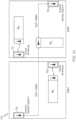
- a medical facility 100 may include a plurality of rooms and/or a plurality of floors (e.g., Rooms A and B on one floor, other rooms may be on other floors).
- one or more medical devices e.g.
- MD A , MD B , and/or MD C and one or more control devices (CD A , CD B , CD C , and/or CD D ), may be distributed amongst the rooms, floors (see FIGS. 1A-1B ), and/or within sub-spaces within a given room (e.g., a large triage room with multiple beds, hospital rooms that are shared by 2 or more subjects, etc.).
- a control device e.g., CD D
- a medical device e.g., MD C
- a control device CD may be any device capable of pairing/unpairing (also referred to herein as connecting/disconnecting) with a medical device, and sending commands to control a medical device.
- a control device may be any device capable of wirelessly pairing with a medical device and issuing commands to the medical device, such as a tethered hand control unit, a wireless hand control unit, a wall mounted control unit, any type of computer (tablet, smartphone, laptop, desktop, etc.), and the like.
- a medical device may any medical device capable of wirelessly pairing/unpairing with a control device, and implementing commands received from a control device.
- a medical device may be a medical bed, a pump, a rail-mounted lift, a computer, and the like.
- a control device (CD A , CD B , CD C , CD D , and/or the like) may be permanently located in a particular location, such as room A or room B.
- a control device may broadcast data having multiple fields, such as a device name field.
- a device name field may be any suitable text, such as a location descriptor ("Control Device A Room A East") that would typically be human-readable and descriptive of its location.
- a control device may be relocated to another location and/or have its device name field updated accordingly.
- a manufacturer-specific data field may include customized data used in the advertising of packets as part of the data broadcast.
- the manufacturer-specific data field may include a company identifier, brand identifier, model identifier, device-type identifier, and the like. In some aspects, this may be followed by additional data, such as 31 octets of data, although any suitable amount/type of data may be utilized in other aspects.
- Any suitable wireless protocol may be utilized, such as Bluetooth, BLE, Zigbee, Z-Wave, 6LoWPAN, Thread, and the like.
- control devices may wirelessly transmit (e.g., via a Bluetooth RF signal and/or radio frequency identification (RFID)) their identifiers (CD A ID, CD B ID, CD C ID, CD D ID, and/or the like) and/or manufacturer-specific data fields (CD A Manu, CD B Manu, CD C Manu, CD D Manu, and/or the like) to medical devices (MD A , MD B , MD C , and/or the like).
- RFID radio frequency identification
- a number of medical devices within range may wirelessly receive the control device identifiers (CD A ID, CD B ID, CD C ID, and/or the like).
- Another control device CD A resides in a different room, namely room A. Both CD A and CD D are broadcasting data, which include the respective device name fields (CD A ID and CD D ID) and the respective manufacturer-specific data fields (CD A Manu and CD D Manu).
- CD A ID and CD D ID the respective device name fields
- CD A Manu and CD D Manu manufacturer-specific data fields
- other control devices are paired with medical devices, and therefore not broadcasting data.
- medical device MD A is paired with control device CD B .
- medical device MD B is paired with control device CD C .
- Paired control devices CD B and CD C are not broadcasting data in this aspect because, once paired, control devices may not broadcast data again until unpaired. In other aspects, control devices may continue broadcasting data to other medical devices during pairing.
- Each medical device e.g., MD C
- Medical device MD C scans the identifiers and manufacturer-specific data received from control devices CD A and CD D .
- a medical device in this aspect may not continue to scan once paired to a control device. In other aspects a medical device may continue to scan while paired to a control device.
- FIG. 1B depicts a block diagram illustrating control devices wirelessly advertising to a medical device and a plurality of medical devices wirelessly paired to other control devices that are distributed amongst the plurality of rooms of the medical facility.
- a control device CD A may pair with a medical device MD C such that the medical device MD C pairs to the identified control device CD A .
- the control device CD A may transmit control signals to the medical device MD C and the medical device MD C may begin to receive control signals (also known as instructions herein) from the control device CD A .
- the medical device MD C may transmit status updates to the control device CD A and the medical device MD C may receive status updates from the control device CD A .
- control device CD A Since the medical device MD C is now paired, control device CD A is no longer broadcasting data. By contrast, control device CD D is still not paired and thus continues broadcasting data.
- medical device MD C may be configured to automatically disassociate from control device CD C over their respective wireless communication channels and/or vice versa if the control device CD C no longer receives any data from the medical device MD C .
- a medical device and/or control device may provide an indicator (visual, audio, and the like) of pairing and/or unpairing.
- FIG. 1C depicts an exemplary medical device graphical interface 110 illustrating a plurality of wireless control devices selectable according to signal strength 114 and/or room location within the medical facility.
- the medical device graphical interface 110 in this aspect is presented on a touch display located on a medical device, although any suitable device capable of displaying a graphical interface 110 may be utilized.
- the medical device is scanning for data broadcast from control devices after having been wheeled into room A.
- medical device actions such as applying the brakes or being plugged into the wall for power may initiate the medical device to begin scanning.
- three control devices are presented as selectable options.
- Each medical device may be presented with its device name field 112, which in this aspect may include the room number in the device name.
- the device name filed 112 may be updated by any appropriate user or administrator.
- any other suitable identifying information may be included (floor, building, control device type, and the like) in the device name field 112.
- Other types of data fields may be utilized for display such as room number, floor number, building, and the like, by which control devices may be sorted and/or filtered.
- Control devices may be filtered by any suitable criteria, such as manufacturer or control device type, which may be contained in the manufacturer-specific data field. In this aspect, control devices from other manufacturers are not displayed even if they are broadcasting data.
- control device options may be sorted by any suitable criteria.
- control devices CD A , CD E , CD F are sorted by their respective Bluetooth signal strengths 114, although any quantity and/or type of sorting criteria may be utilized, such as room number, floor number, manufacturer, and the like.
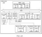
- FIG. 2A depicts illustrative internal components of a control device 200 that are communicatively coupled to one another to provide wireless link pairing with and control of a medical device, according to one or more embodiments of the present disclosure.
- the control device 200 may include a local interface 202 (e.g., a bus) that communicatively interconnects the various components, including, but not limited to, a processing device 204, memory 206, input/output hardware 208, network interface hardware 210, and/or a data storage device 212.
- a local interface 202 e.g., a bus
- the processing device 204 such as a computer processing unit (CPU), may be the central processing unit of the control device 200, performing calculations and logic operations required to execute a program.
- the processing device 204 alone or in conjunction with one or more of the other elements disclosed in FIG. 2A , is an illustrative processing device, computing device, processor, or combination thereof, as such terms are used in this disclosure.
- the memory 206 such as read only memory (ROM) and random access memory (RAM), may constitute illustrative memory devices (i.e., non-transitory, processor-readable storage media).
- Such memory 206 may include one or more programming instructions thereon that, when executed by the processing device 204, cause the processing device 204 to complete various processes, such as the processes described herein.
- the program instructions may be stored on a tangible computer-readable medium such as a digital disk, flash memory, a memory card, a USB drive, an optical disc storage medium (e.g., Blu-ray TM , CD, DVD), and/or other non-transitory processor-readable storage media.
- the program instructions contained on the memory 206 may be embodied as a plurality of software modules, where each module provides programming instructions for completing one or more tasks.
- the memory 206 may contain one or more of operating logic 214, communications logic 216, and UI logic 218. It should be understood that the various logic modules described herein with respect to FIG. 2A are merely illustrative, and that other logic modules, including logic modules that combine the functionality of two or more of the modules described hereinabove, may be used without departing from the scope of the present disclosure.
- the data storage device 212 which may generally be a storage medium that is separate from the memory 206, may contain a data repository for storing electronic data and/or the like relating to the location of the control device 200, an identification of the control device 200, configuration settings, UI data, and/or the like.
- the data storage device 212 may be any physical storage medium, including, but not limited to, a hard disk drive (HDD), memory, removable storage, and/or the like. While the data storage device 212 is depicted as a local device, it should be understood that the data storage device 212 may be a remote storage device that is remotely located from the control device 200, such as, for example, a server computing device or the like.
- Illustrative data that may be contained within the data storage device 212 may include, for example, location data 220, configuration data 222, UI data 224, pairing data 226, and/or the like.
- Pairing data 226 may include identification data (serial number, etc.) one or more medical device identifiers to which the control device 200 is or has been paired via the methods as described herein.
- the input/output hardware 208 may generally include a wireless system 230, an indicator 232, a location system 234, and a user interface system 236.
- the wireless system 230 may include a transceiver 242 configured to transmit and to receive wireless signals (e.g., RF, Bluetooth, UWB, and/or the like) according to the respective wireless protocols.
- wireless signals e.g., RF, Bluetooth, UWB, and/or the like
- the indicator 232 may include a light emitting diode, indicator light, and/or the like.
- the location system 234 may include a Global Positioning System (GPS), a Global Navigation Satellite System (GLONASS), a Wi-Fi locating system, and/or the like.
- the user interface system 236 may include a display 244 and/or user interface controls 246 configured to receive control inputs for transmission via the input/output hardware 208 and to display outputs received from the input/output hardware 208.
- the network interface hardware 210 may generally provide the control device 200 with an ability to interface with one or more external devices, such as, for example, a medical facility server, a nurse station, and/or the like. Communication with external devices may occur using various communication ports (not shown). An illustrative communication port may be attached to a communications network, such as the Internet, an intranet, a local network, a direct connection, and/or the like.
- the input/output hardware 208 and the network interface hardware 210 may be combined into a single device that allows for communications with other devices, regardless of whether such other devices are located within the control device 200.
- FIG. 2A is merely illustrative and are not intended to limit the scope of the present disclosure. More specifically, while the components in FIG. 2A are illustrated as residing within the control device, this is a non-limiting example. In some embodiments, one or more of the components may reside external to the control device. Similarly, one or more of the components may be embodied in other devices not specifically described herein. Furthermore, various control devices are described herein (e.g., FIG. 3 ) and are non-limiting examples. Other control devices may include a user's personal cell-phone, a nurse's call system device, and/or the like with wireless communication channel capabilities.
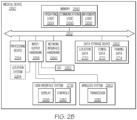
- FIG. 2B depicts illustrative internal components of a medical device 250 that are communicatively coupled to one another to provide wireless link pairing with a control device, according to one or more embodiments of the present disclosure.
- the medical device 250 may include a local interface 252 (e.g., a bus) that communicatively interconnects the various components, including, but not limited to, a processing device 254, memory 256, input/output hardware 258, network interface hardware 260, and/or a data storage device 262.
- a local interface 252 e.g., a bus
- the processing device 254 such as a computer processing unit (CPU), may be the central processing unit of the medical device 250, performing calculations and logic operations required to execute a program.
- the processing device 254 alone or in conjunction with one or more of the other elements disclosed in FIG. 2B , is an illustrative processing device, computing device, processor, or combination thereof, as such terms are used in this disclosure.
- the memory 256 such as read only memory (ROM) and random access memory (RAM), may constitute illustrative memory devices (i.e., non-transitory, processor-readable storage media).
- Such memory 256 may include one or more programming instructions thereon that, when executed by the processing device 254, cause the processing device 254 to complete various processes, such as the processes described herein.
- the program instructions may be stored on a tangible computer-readable medium such as a digital disk, flash memory, a memory card, a USB drive, an optical disc storage medium (e.g., Blu-ray TM , CD, DVD), and/or other non-transitory processor-readable storage media.
- the program instructions contained on the memory 256 may be embodied as a plurality of software modules, where each module provides programming instructions for completing one or more tasks.
- the memory 256 may contain one or more of operating logic 264, communications logic 266, and movement logic 268. It should be understood that the various logic modules described herein with respect to FIG. 2B are merely illustrative, and that other logic modules, including logic modules that combine the functionality of two or more of the modules described hereinabove, may be used without departing from the scope of the present disclosure.
- the data storage device 262 which may generally be a storage medium that is separate from the memory 256, may contain a data repository for storing electronic data and/or the like relating to the location of the medical device 250, an identification of the medical device 250, configuration settings, and/or the like.
- the data storage device 262 may be any physical storage medium, including, but not limited to, a hard disk drive (HDD), memory, removable storage, and/or the like. While the data storage device 262 is depicted as a local device, it should be understood that the data storage device 262 may be a remote storage device that is remotely located from the medical device 250, such as, for example, a server computing device or the like.
- Illustrative data that may be contained within the data storage device 262 may include, for example, location data 270, configuration data 272, pairing data 274, and/or the like.
- Pairing data 274 may include one or more control device identifiers to which the medical device 250 is or has been paired via the methods as described herein.
- the input/output hardware 258 may generally include a user interface system 278, a wireless system 280, an indicator 282, and a location system 284.
- the user interface system 278 may include a display 288 and/or user interface controls 290 configured to receive control inputs for transmission via the input/output hardware 258 and to display outputs received from the input/output hardware 258.
- the wireless system 280 may include a transceiver 292 configured to transmit and to receive wireless signals (e.g., RFID, RF, Bluetooth, UWB, and/or the like) according to the respective wireless protocols.
- wireless signals e.g., RFID, RF, Bluetooth, UWB, and/or the like
- data transmission techniques including encryption/decryption, forward error correction, and/or the like may be instituted.
- the indicator 282 may include a light emitting diode, indicator light, and/or the like.
- the location system 284 may include a Global Positioning System (GPS), a Global Navigation Satellite System (GLONASS), a Wi-Fi locating system, and/or the like.
- GPS Global Positioning System
- GLONASS Global Navigation Satellite System
- Wi-Fi locating system and/or the like.
- the network interface hardware 260 may generally provide the medical device 250 with an ability to interface with one or more external components, such as, for example, a medical facility server, a nurse station, and/or the like. Communication with external devices may occur using various communication ports (not shown). An illustrative communication port may be attached to a communications network, such as the Internet, an intranet, a local network, a direct connection, and/or the like.
- the input/output hardware 258 and the network interface hardware 260 may be combined into a single device that allows for communications with other devices, regardless of whether such other devices are located within the medical device 250.
- FIG. 2B is merely illustrative and are not intended to limit the scope of this disclosure. More specifically, while the components in FIG. 2B are illustrated as residing within the medical device 250, this is a non-limiting example. In some embodiments, one or more of the components may reside external to the medical device 250. Similarly, one or more of the components may be embodied in other devices not specifically described herein.
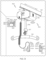
- FIG. 3 depicts one illustrative wireless link pairing system 300 including a rail-mounted lift 302 as an illustrative medical device and a plurality of remote devices 304, 306, 308, as control devices, according to one or more embodiments of the present disclosure.
- the rail-mounted lift 302 is coupled to a rail 310.
- the rail 310 may extend along a ceiling of a room (e.g., Room A of FIG. 1 ), along a ceiling of more than one room (e.g., Room A and Room B of FIG. 1 ), and/or the like.
- the rail-mounted lift 302 includes a lift unit 312 that is slidably coupled to the rail 310 via a carriage 314.
- the lift unit 312 may be used to support and/or lift a subject with a lifting strap 316 which is coupled to a motor (not shown) contained within the lift unit 312.
- the motor facilitates extending or retracting the lifting strap 316 from the lift unit 312, thereby raising and lowering a subject attached to the lifting strap 316.
- a subject may be attached to the lifting strap 316 with a sling bar 318 or a similar accessory attached to the lifting strap 316 via a coupling 317.
- the sling bar 318 or a similar accessory may be attached to a harness or a sling in which the subject is positioned, thereby facilitating the lifting operation.
- Various components of the rail-mounted lift 302, such as the lift unit 312 and/or components thereof, may be operated with a tethered hand control unit 304, a wireless hand control unit 306 and/or a wall-mounted control unit 308 communicatively couplable to the lift unit 312.
- the tethered hand control unit 304 may be directly wired to the lift unit 312 and/or wirelessly coupled or paired to the lift unit 312 (e.g., according to the methods described herein) to facilitate remote operation of the rail-mounted lift 302.
- the tethered hand control unit 304 may include a display 320 and one or more user interface controls 322A (e.g., to extend lifting strap 316), 322B (e.g., to retract lifting strap 316).
- the wireless hand control unit 306 may be wirelessly coupled or paired to the lift unit 312 (e.g., according to the methods described herein) and may include a display 324 and one or more user interface controls 326A (e.g., to extend lifting strap 316), 326B (e.g., to retract lifting strap), 326C (e.g., to translate lift unit 312 in a first lateral direction L1 along rail 310), 326D (e.g., to translate lift unit 312 in a second lateral direction L2 along rail 310), and the wall-mounted control unit 308 may be wirelessly coupled or paired to the lift unit 312 (e.g., according to the methods described herein) and may include a display 328 and one or more user interface controls
- Further user interface controls of the wall-mounted control unit 308 may activate the lift unit 312, pair a subject with the lift unit 312, return the lift unit 312 to a "home" position/location, receive information from the lift unit 312 (e.g., battery status, magnitude of load supported by the lift unit, and/or the like), actuate an emergency stop of the lift unit 312, reset the lift unit 312, and/or the like.
- information from the lift unit 312 e.g., battery status, magnitude of load supported by the lift unit, and/or the like
- actuate an emergency stop of the lift unit 312 reset the lift unit 312, and/or the like.
- the rail-mounted lift 302 may be operated with a sling bar control unit 400 positioned on the sling bar 318 and/or a coupling control unit 410 positioned on the coupling 317 attached to a distal "D" end of the lifting strap 316.
- the sling bar control unit 400 may be wirelessly coupled or paired to the lift unit 312 (e.g., according to the methods described herein) and may include one or more user interface controls 402A (e.g., to extend lifting strap 316), 402B (e.g., to retract lifting strap 316).
- the coupling control unit 410 may be wirelessly coupled or paired to the lift unit 312 (e.g., according to the methods described herein) and may include one or more user interface controls 412A (e.g., to extend lifting strap 316), 412B (e.g., to retract lifting strap 316).
- user interface controls 412A e.g., to extend lifting strap 316
- 412B e.g., to retract lifting strap 316.
- a plurality of control devices may already be physically present in a room in the aspect.
- control devices may be physically brought into the room, and/or physically taken out of the room.
- a medical device e.g., the rail-mounted lift 302 may be fixedly positioned within a room. In such aspects, referring to FIGS.
- control devices that physically remain in that room e.g., wall-mounted control unit 308 and physically remain coupled to the medical device itself in that room (e.g., tethered hand control unit 304, coupling control unit 410), remain wirelessly connected to the medical device, and the medical device may be configured to remain paired with one or more of such control devices.
- the rail-mounted lift 302 may store pairing data ( FIG. 2B , reference 274, e.g., associated CD IDs in a fixed pairings file), in its data storage device ( FIG. 2B , reference 262) for each control device that physically remains in its room and/or physically remains coupled to the rail-mounted lift 302. Further in such aspects, referring to FIGS.
- one or more control devices may not physically remain in that room (e.g., wireless hand control unit 306, sling bar control unit 400).
- the medical device may be configured to not only pair with such control devices as they are brought into a room but also periodically or continually monitor pairings with such control devices. Periodically, as described herein, may refer to a regularly occurring interval or time period (e.g., every "X" seconds, every "Y” minutes, and/or the like).
- the rail-mounted lift 302 may store pairing data (e.g., FIG. 2B , reference 274, e.g., associated CD IDs in a transient pairings file), in its data storage device (e.g., FIG.
- each control device identifier e.g., CD ID
- the medical device e.g., rail-mounted lift
- the medical device may remain paired with that control device and if the paired control device identifier is not still being wirelessly received, the medical device may automatically disassociate from that control device (e.g., the medical device considered as physically taken out of the room).
- a medical device may not be fixedly positioned within a room.
- a lift unit may be moved along a rail 310 ( FIG. 3 ) from one room (e.g., FIG. 1 , Room A) to another room (e.g., FIG. 1 , Room B).
- control devices that physically remain coupled to the medical device itself e.g., tethered hand control unit 304, coupling control unit 410
- the rail-mounted lift 302 may store pairing data ( FIG.
- one or more control devices may not be physically coupled to the medical device itself. This may include control devices that physically remain in a given room (e.g., wall-mounted control units 308) and/or control devices that may not physically remain in any given room (e.g., wireless hand control unit 306, sling bar control unit 400). In such aspects, the medical device may be configured to not only pair with such control devices but also periodically or continually monitor pairings with such control devices.
- the rail-mounted lift 302 may store pairing data (e.g., FIG. 2B , reference 274, e.g., associated CD IDs in a transient pairings file), in its data storage device (e.g., FIG. 2B , reference 262) for each control device that physically remains in a given room and that may not physically remain in any given room and the rail-mounted lift 302 may periodically determine whether each control device identifier (e.g., CD ID) is still communicating with the rail-mounted lift 302 over its wireless communication channel.
- pairing data e.g., FIG. 2B , reference 274, e.g., associated CD IDs in a transient pairings file
- the medical device upon detecting movement (e.g., translation along rail 310) the medical device may be configured to continually monitor pairings with such control devices. Accordingly, if a control device identifier (e.g., CD ID of a wireless hand control unit 306 being used to translate or move the rail-mounted lift 302 between rooms, CD ID of a sling bar control unit 400 being moved with the rail-mounted lift 302 between rooms) or other data is still being wirelessly received, the medical device (e.g., rail-mounted lift) may remain paired with the control device(s) and if the control device identifier (e.g., CD ID of a wall-mounted control unit 308 in a former room, CD ID of a sling bar control unit 400 not moved to a new room) or other data from the control device is not still being wirelessly received, the medical device may automatically disassociate from any such control device(s). Further in such an aspect, the medical device may be configured to provide on its graphical interface 110 for pairing new control devices (e.
- FIG. 5 depicts a flow diagram of an illustrative method 500 for pairing a medical device and a control device using a wireless channel, according to one or more embodiments of the present disclosure.
- a medical device MD X 502 may identify and pair with a control device CD X 504, wherein the dashed vertical line in the center of the flow diagram demarcates the respective operations of the medical device MD X 502 and the control device CD X 504.
- the CD X may be unpaired and wirelessly broadcast self-identifying data, which may include a device name and/or manufacturer-specific data (manufacturer, brand, model, device, type, and the like).
- the MD X may scan for wireless broadcasts based upon receiving input (such as a user pressing a button on MD X or a button within the medical device interface) or satisfying a scanning criterion.
- MD X may be a bed, in which setting its brakes or being plugged into a wall for power may automatically cause MD X to scan for control devices.
- Setting the brakes or being plugged into the wall may be criteria that indicate, for example, that MD X has reached its intended destination (such as a particular room or partition within a room) and scanning is now appropriate. In this way, MD X can conserve power by avoiding unnecessary scanning until a destination has been reached.
- the medical device MD X may receive the identifying data wirelessly broadcast from CD X .
- the wireless broadcast from CD X in block 506 is depicted as intersecting within the flowchart prior to the scanning by MD X at block 508, the wireless broadcast in block 506 may intersect at any point up and/or including reception of the CD X at block 510.
- the medical device MD X may output information to the interface (e.g., FIG. 1C ) identifying the control device CD X , in which the manufacturer-specific data may be filtered (e.g., handheld control devices from a specific manufacturer may be displayed for selection on the interface).
- the medical device MD X may receive input at the interface selecting the control device.
- a user may touch a screen selecting CD X from among other eligible control devices.
- the medical device MD X may send wireless confirmation of the pairing to the control device CD X .
- the medical device interface may add the medical device MD X to the list of selectable medical devices.
- the control device CD X may receive pairing confirmation.
- the control device CD X may provide an indication of pairing/unpairing events, such as the indicator 232 in FIG. 2A , which may be a light such as an LED.
- the control device CD X may stop its wireless broadcast due to being paired with a medical device MD X .
- the control device CD X may send one or more commands to the medical device MD X .
- the medical device MD X may receive the one or more commands from the control device CD X .
- the medical device MD X may physically interact with a user.
- physical interaction with a user may include, by way of non-limiting examples, taking diagnostics or measurements (size/proportions, weight, temperature, heartrate, glucose, blood pressure, brainwaves, biorhythms, and the like) of a user, introducing or removing any suitable substance from any part of a user, diagnosing and/or alleviating/treating any disease or other ailment of a user, and/or assisting with the support, mobility, positioning, restraint, and/or comfort of the user.
- diagnostics or measurements size/proportions, weight, temperature, heartrate, glucose, blood pressure, brainwaves, biorhythms, and the like
- the medical device MD X may send wireless confirmation of unpairing, which may be accomplished via the medical device interface. This may be, for example, when the medical device MD X (a bed in this non-limiting example) is being moved to another room.
- the control device CD X may receive subsequent confirmation of the unpairing. In some aspects, this may entail a visual, audio, or other indication associated with the control device CD X , such as the indicator 232 in FIG. 2A .
- the control device CD X may resume broadcasting self-identifying data in order to become paired with another medical device, such as a different bed that may be wheeled into the room in which CD X resides.
- the medical device MD X may perform an updated scan for wireless broadcasts. This may be done, for example, when the medical device MD X has been wheeled into another room such that the brakes are engaged and/or the medical device MD X is plugged into the wall.
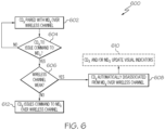
- FIG. 6 depicts a flow diagram of an illustrative method 600 for a control device to issue commands or control inputs to a paired medical device, according to one or more embodiments of the present disclosure.
- method 600 may be utilized for all control functions or only certain functions (e.g., actuating a motor, turning on a pump, and/or the like).
- a control device CD X may be paired with a medical device MD X over its wireless communication channel, as described herein.
- the control device CD X may be configured to determine (e.g., based on inputs received via user interface controls 246 of FIG.
- the control device CD X may remain paired with the medical device identifier MD X ID over its wireless communication channel at block 602. If it is determined that a command or control input is to be issued or transmitted to the medical device MD X , the control device CD X may be configured to determine whether the wireless communication channel is weak (e.g., below a predetermined threshold wireless signal strength) at decision block 606.
- the control device CD X may be configured to automatically disassociate from the medical device MD X over the wireless communication channel at block 608.
- the control device CD X may be configured to update its visual indicator to reflect the disassociation (e.g., LED off). If it is determined that the wireless communication channel is not weak, the control device CD X may be configured to, at block 620, issue the command or control input to the medical device MD X over its wireless communication channel.
- a medical device MD X if a medical device MD X is moved to an out-of-range location (e.g., no longer within the wireless range of the control device CD X ), then the control device CD X may be unable to issue a command or control input to the medical device MD X , despite being otherwise able to over a strong wireless communication channel.
- the control device 200 may include a location system 234 and the medical device 250 may include a location system 284.
- the medical device 250 and/or the control device 200 may be configured to further transmit their respective location information (e.g., MD LOC, CD LOC) with their respective identifiers (e.g., MD ID, CD ID) as described herein.
- the control device 200 may be configured to compare a received MD LOC (from the medical device) with its CD LOC as part of its process of pairing with a medical device.
- an initial range (e.g., about 2 m to about 5 m radius) may be used for initial pairing and a control range (e.g., average size of room) may be used for disassociation.
- the control device 200 may be configured to adjust/correct its CD LOC as well as the received MD LOC using a medical facility location MF LOC location beacon with known coordinates.
- the medical device 250 may be configured to adjust/correct its MD LOC using a medical facility location MF LOC location beacon with known coordinates.
- each wireless communication channel (e.g., Bluetooth channel) may be configured as a single-path communication channel or a dual-path communication channel.
- the systems and methods described herein are suitable for pairing a medical device and a control device using a wireless link (e.g., Bluetooth channel).
- a wireless link e.g., Bluetooth channel
- the systems and methods described herein identify a configurable, pairable wireless connection (e.g. Bluetooth channel) to be used to execute control actions for a medical device (e.g., a portable medical bed) to ensure that the control inputs are coming from a control device (e.g., a tethered hand control unit, a wireless hand control unit, a wall-mounted control unit, a sling bar control unit, a coupling control unit, and/or the like) located in the same room as the medical device.
- a control device e.g., a tethered hand control unit, a wireless hand control unit, a wall-mounted control unit, a sling bar control unit, a coupling control unit, and/or the like
- Such systems and methods ensure that the control inputs coming from the control device are
Landscapes
- Engineering & Computer Science (AREA)
- Health & Medical Sciences (AREA)
- Biomedical Technology (AREA)
- Computer Networks & Wireless Communication (AREA)
- Signal Processing (AREA)
- General Health & Medical Sciences (AREA)
- Business, Economics & Management (AREA)
- General Business, Economics & Management (AREA)
- Medical Informatics (AREA)
- Public Health (AREA)
- Epidemiology (AREA)
- Primary Health Care (AREA)
- Computer Security & Cryptography (AREA)
- Databases & Information Systems (AREA)
- Computing Systems (AREA)
- Vascular Medicine (AREA)
- Anesthesiology (AREA)
- Heart & Thoracic Surgery (AREA)
- Hematology (AREA)
- Life Sciences & Earth Sciences (AREA)
- Animal Behavior & Ethology (AREA)
- Veterinary Medicine (AREA)
- Selective Calling Equipment (AREA)
- Accommodation For Nursing Or Treatment Tables (AREA)
Claims (10)
- System zum unterstützten Koppeln von Vorrichtungen, wobei das System Folgendes umfasst:eine koppelbare Steuervorrichtung (200), umfassend:ein erstes Kommunikationssystem, das so konfiguriert ist, dass es über einen Kommunikationskanal kommuniziert;einen Prozessor (204); undeinen Speicher (206), der erste Programmanweisungen speichert, wobei die Programmanweisungen, wenn sie von dem ersten Prozessor ausgeführt werden, bewirken, dass der Prozessor:drahtlos selbst identifizierende Daten überträgt, die auf nicht gekoppelt sein basieren;Kopplungsbestätigung von einer medizinischen Vorrichtung (250) empfängt;das drahtlose Übertragen als Reaktion auf die empfangene Kopplungsbestätigung stoppt;eine nachfolgende Entkopplungsbestätigung von der medizinischen Vorrichtung (250) empfängt; unddas Übertragen der selbst identifizierende Daten als Reaktion auf Empfangen der Entkopplungsbestätigung wieder aufnimmt; undwobei die medizinische Vorrichtung (250) Folgendes umfasst:eine Anzeigevorrichtung, die so konfiguriert ist, dass sie eine Benutzeroberfläche (110) anzeigt; undein zweites Kommunikationssystem, das so konfiguriert ist, dass es über den Kommunikationskanal kommuniziert, wobei die medizinische Vorrichtung (250) so konfiguriert ist, dass sie:basierend auf empfangener Eingabe oder Erfüllen eines Scan-Kriteriums auf drahtlose Übertragung scannt;basierend auf dem Scan identifizierende Daten empfängt, die von einer Vielzahl von Steuervorrichtungen (200) drahtlos übertragen werden;Informationen an die Benutzeroberfläche (110) ausgibt, die die Vielzahl von Steuervorrichtungen (200) identifizieren;wobei die von der Vielzahl von Steuervorrichtungen (200) empfangenen identifizierende Daten auf der Benutzeroberfläche (110) gemäß einem Filterkriterium und einem Sortierungskriterium dargestellt werden;wobei das Sortierungskriterium Standortinformationen innerhalb der identifizierenden Daten oder jeweilige Signalstärken (114) von jeder drahtlosen Übertragung umfasst;eine Eingabe von der Benutzeroberfläche (110) zum Auswählen von einer der Vielzahl von Steuervorrichtungen (200) empfängt;eine drahtlose Bestätigung des Koppelns an die ausgewählte Steuervorrichtung (200) sendet;nachfolgend eine drahtlose Bestätigung der Entkoppelung an die Steuervorrichtung (200) sendet; undals Reaktion auf die Entkoppelung basierend auf empfangener Eingabe oder Erfüllen des Scan-Kriteriums einen Scan nach drahtlosen Übertragungen durchführt.
- System nach Anspruch 1, wobei die koppelbare medizinische Vorrichtung (250) ein medizinisches Bett, eine Pumpe, einen auf Schienen montierten Lift (302) oder einen Computer umfasst.
- System nach Anspruch 1 oder 2, wobei das Scan-Kriterium darauf basiert, dass die medizinische Vorrichtung (250) für Stromversorgung eingesteckt ist oder ihre Bremsen angezogen sind.
- System nach Anspruch 1, 2 oder 3, wobei:
das Filterkriterium einen Vorrichtungshersteller, einen Vorrichtungstyp oder ein Vorrichtungsmodell umfasst. - System nach einem vorstehenden Anspruch, wobei die selbst identifizierenden Daten ein erstes Datenfeld umfassen, das einen Vorrichtungsnamen umfasst, und ein zweites Datenfeld, das Herstellerdaten umfasst.
- System nach Anspruch 5, wobei die Herstellerdaten weiter eine für einen Hersteller einmalige Kennung gefolgt von zwischen 1 und 31 Daten-Oktetten umfassen.
- Verfahren zum unterstützten drahtlosen Koppeln einer medizinischen Vorrichtung (250) mit einer Steuervorrichtung (200), wobei das Verfahren Folgendes umfasst:Scannen, an der medizinischen Vorrichtung (250), nach drahtlosen Übertragungen basierend auf empfangener Eingabe oder Erfüllen eines Scan-Kriteriums;Empfangen, basierend auf dem Scan von identifizierenden Daten, die von einer Vielzahl von Steuervorrichtungen (200) drahtlos übertragen werden;Ausgeben, an eine Benutzeroberfläche (110) an der medizinischen Vorrichtung (250), von Informationen, die die Vielzahl von Steuervorrichtungen (200) identifizieren;wobei die von der Vielzahl von Steuervorrichtungen (200) empfangenen identifizierende Daten auf der Benutzeroberfläche (110) gemäß einem Filterkriterium und einem Sortierungskriterium dargestellt werden;wobei das Sortierungskriterium Standortinformationen innerhalb der identifizierenden Daten oder jeweilige Signalstärken (114) von jeder drahtlosen Übertragung umfasst;Empfangen von Eingabe von der Benutzeroberfläche (110) zum Auswählen einer der Vielzahl von Steuervorrichtungen (200);Senden einer drahtlosen Bestätigung des Koppelns an die ausgewählte Steuervorrichtung (200);Empfangen eines Befehls von der Steuervorrichtung (200);physisches Interagieren mit einem Benutzer basierend auf dem von der Steuervorrichtung (200) empfangenen Befehl;nachfolgendes Senden einer drahtlosen Bestätigung des Entkoppelns an die Steuervorrichtung (200); undDurchführen eines aktualisierten Scans nach drahtlosen Übertragungen als Reaktion auf die Entkoppelung basierend auf empfangener Eingabe oder Erfüllen des Scan-Kriteriums.
- Verfahren nach Anspruch 7, wobei die koppelbare medizinische Vorrichtung (250) ein medizinisches Bett, eine Pumpe, einen auf Schienen montierten Lift (302) oder einen Computer umfasst.
- Verfahren nach Anspruch 7 oder 8, wobei das Scan-Kriterium darauf basiert, dass die medizinische Vorrichtung (250) eingesteckt ist oder ihre Bremsen angezogen sind.
- Verfahren nach Anspruch 7, 8 oder 9, wobei:
das Filterkriterium einen Vorrichtungshersteller, einen Vorrichtungstyp oder ein Vorrichtungsmodell umfasst.
Applications Claiming Priority (1)
| Application Number | Priority Date | Filing Date | Title |
|---|---|---|---|
| US202063127629P | 2020-12-18 | 2020-12-18 |
Publications (2)
| Publication Number | Publication Date |
|---|---|
| EP4016535A1 EP4016535A1 (de) | 2022-06-22 |
| EP4016535B1 true EP4016535B1 (de) | 2025-05-28 |
Family
ID=79024489
Family Applications (1)
| Application Number | Title | Priority Date | Filing Date |
|---|---|---|---|
| EP21214707.8A Active EP4016535B1 (de) | 2020-12-18 | 2021-12-15 | Koppelbare vorrichtungen und systeme und verfahren zur bereitstellung einer unterstützten kopplung von vorrichtungen an bestimmte orte |
Country Status (3)
| Country | Link |
|---|---|
| US (2) | US12342413B2 (de) |
| EP (1) | EP4016535B1 (de) |
| CN (1) | CN114650519A (de) |
Families Citing this family (3)
| Publication number | Priority date | Publication date | Assignee | Title |
|---|---|---|---|---|
| EP4016535B1 (de) * | 2020-12-18 | 2025-05-28 | Hill-Rom Services, Inc. | Koppelbare vorrichtungen und systeme und verfahren zur bereitstellung einer unterstützten kopplung von vorrichtungen an bestimmte orte |
| WO2025091233A1 (zh) * | 2023-10-31 | 2025-05-08 | 南京迈瑞生物医疗电子有限公司 | 手术室控制系统及无线接入方法、存储介质 |
| US12387374B1 (en) * | 2023-12-15 | 2025-08-12 | Amazon Technologies, Inc. | Localization of devices in a structure |
Family Cites Families (30)
| Publication number | Priority date | Publication date | Assignee | Title |
|---|---|---|---|---|
| US8244179B2 (en) | 2005-05-12 | 2012-08-14 | Robin Dua | Wireless inter-device data processing configured through inter-device transmitted data |
| EP2001188A1 (de) | 2007-06-08 | 2008-12-10 | F.Hoffmann-La Roche Ag | Verfahren zur Authentifizierung einer medizinischen Vorrichtung und einer Fernbedienungsvorrichtung |
| US8932250B2 (en) * | 2007-06-15 | 2015-01-13 | Animas Corporation | Systems and methods to pair a medical device and a remote controller for such medical device |
| US8059573B2 (en) * | 2007-07-30 | 2011-11-15 | Qualcomm Incorporated | Method of pairing devices |
| US11244745B2 (en) * | 2010-01-22 | 2022-02-08 | Deka Products Limited Partnership | Computer-implemented method, system, and apparatus for electronic patient care |
| US20120182939A1 (en) * | 2011-01-14 | 2012-07-19 | Qualcomm Incorporated | Telehealth wireless communication hub and service platform system |
| JP5988835B2 (ja) * | 2012-11-08 | 2016-09-07 | オリンパス株式会社 | 無線送信端末、無線受信端末、無線通信システム、無線通信方法、およびプログラム |
| US9357336B2 (en) * | 2012-12-03 | 2016-05-31 | Samsung Electronics Co., Ltd. | Information providing method and mobile terminal therefor |
| CN103297099B (zh) | 2013-06-26 | 2015-08-19 | 上海合合信息科技发展有限公司 | 蓝牙通信方法及蓝牙通信设备 |
| US9830424B2 (en) * | 2013-09-18 | 2017-11-28 | Hill-Rom Services, Inc. | Bed/room/patient association systems and methods |
| US9779226B2 (en) * | 2013-12-18 | 2017-10-03 | Medtronic Minimed, Inc. | Fingerprint enhanced authentication for medical devices in wireless networks |
| US10085905B2 (en) * | 2014-08-11 | 2018-10-02 | Stryker Corporation | Patient support apparatuses with wireless headwall communication |
| US9924298B2 (en) | 2014-10-31 | 2018-03-20 | Welch Allyn, Inc. | Wireless ambulatory care network |
| CA2974080A1 (en) * | 2015-01-21 | 2016-07-28 | Smiths Medical Asd, Inc. | Medical device control |
| US9763644B2 (en) | 2015-03-27 | 2017-09-19 | Clarius Mobile Health Corp. | System and method for connecting and controlling wireless ultrasound imaging system from electronic device |
| US9848075B1 (en) * | 2015-05-14 | 2017-12-19 | Invoy Technologies, Llc | Communication system for pairing user devices with medical devices |
| US10445467B2 (en) * | 2016-03-15 | 2019-10-15 | Karl Storz Imaging, Inc. | System and method to restrict the operational range of wireless devices |
| US10524123B2 (en) | 2016-03-30 | 2019-12-31 | Zoll Medical Corporation | Establishing secure communication at an emergency care scene |
| US10360787B2 (en) | 2016-05-05 | 2019-07-23 | Hill-Rom Services, Inc. | Discriminating patient care communications system |
| US10705579B2 (en) | 2016-07-11 | 2020-07-07 | Dell Products, L.P. | Information handling system having regional cooling |
| EP4542931A3 (de) * | 2016-10-18 | 2025-06-18 | DexCom, Inc. | System und verfahren zur kommunikation von analytdaten |
| JP2020505859A (ja) * | 2017-01-30 | 2020-02-20 | コーニンクレッカ フィリップス エヌ ヴェKoninklijke Philips N.V. | 身体上存在の確認及びペアリング解除の容易化のトリガとしてのセンサデータ品質 |
| EP3622529A1 (de) * | 2017-05-08 | 2020-03-18 | Masimo Corporation | System zur paarung eines medizinischen systems mit einem netzwerksteuergerät mittels dongle |
| US10290371B1 (en) | 2018-01-30 | 2019-05-14 | General Electric Company | System of medical devices and method of controlling the same |
| EP3847834A1 (de) * | 2018-09-07 | 2021-07-14 | 7Hugs Labs | System, verfahren und vorrichtung zur paarung von baken |
| CN109936840B (zh) * | 2019-01-02 | 2023-01-03 | 百度在线网络技术(北京)有限公司 | 通信方法、装置及电子设备 |
| CN109803168A (zh) | 2019-01-07 | 2019-05-24 | Oppo广东移动通信有限公司 | 分体式设备的控制方法和装置 |
| US11266831B2 (en) * | 2019-02-21 | 2022-03-08 | Envoy Medical Corporation | Implantable cochlear system with integrated components and lead characterization |
| EP3748646A1 (de) * | 2019-06-04 | 2020-12-09 | Liko Research & Development AB | Authentifizierung einer drahtlosen verbindungspaarung |
| EP4016535B1 (de) * | 2020-12-18 | 2025-05-28 | Hill-Rom Services, Inc. | Koppelbare vorrichtungen und systeme und verfahren zur bereitstellung einer unterstützten kopplung von vorrichtungen an bestimmte orte |
-
2021
- 2021-12-15 EP EP21214707.8A patent/EP4016535B1/de active Active
- 2021-12-15 US US17/551,683 patent/US12342413B2/en active Active
- 2021-12-15 CN CN202111540165.4A patent/CN114650519A/zh active Pending
-
2025
- 2025-05-19 US US19/212,076 patent/US20250280280A1/en active Pending
Also Published As
| Publication number | Publication date |
|---|---|
| US20250280280A1 (en) | 2025-09-04 |
| US20220201460A1 (en) | 2022-06-23 |
| EP4016535A1 (de) | 2022-06-22 |
| US12342413B2 (en) | 2025-06-24 |
| CN114650519A (zh) | 2022-06-21 |
Similar Documents
| Publication | Publication Date | Title |
|---|---|---|
| US20250280280A1 (en) | Pairable devices and systems and methods for providing assisted pairing of devices to particular locations | |
| US9501430B2 (en) | X-ray imaging system, information processing apparatus, methods for controlling x-ray imaging system and information processing apparatus, and recording medium | |
| US11690114B2 (en) | Wireless link pairing authentication | |
| US20140343967A1 (en) | Methods to Improve Workflow by Automatically Adding Patient Identification | |
| EP3089623B1 (de) | Aufblasbare luftmatratze mit integrierter steuerung | |
| US9769868B2 (en) | Measurement device | |
| US10320853B2 (en) | Method and apparatus for supporting facility control of terminal | |
| US20140324231A1 (en) | Air conditioning system and remote controller | |
| JP4087814B2 (ja) | 無線通信システム | |
| JP5953818B2 (ja) | 空気調和機 | |
| EP2651144A1 (de) | Anzeigevorrichtung, Peripherievorrichtungen, Fernsteuerung und Steuerungsverfahren dafür | |
| US12117797B2 (en) | Lift communications systems comprising wall-mounted displays and methods of using and configuring the same | |
| JP5675283B2 (ja) | 無線通信装置 | |
| US20230269401A1 (en) | Geolocationing system and method for use of same | |
| US12022537B2 (en) | Wireless link pairing authentication | |
| US10368387B2 (en) | Method for transmitting data in wireless system | |
| KR20150005770A (ko) | 설비의 통신 진단 시스템 및 방법 | |
| KR101836379B1 (ko) | 리모컨에서 제어 가능한 디바이스에 대한 페어링을 수행하기 위한 장치 및 방법 | |
| JP2018195895A (ja) | 制御装置、空気調和機、端末装置、制御方法、および制御プログラム | |
| CN110996765B (zh) | 患者监测 | |
| JP2013111198A (ja) | 放射線撮影システムおよび制御ユニット | |
| KR20150138829A (ko) | 적어도 하나의 환자 엔트리를 활성화하기 위한 방법 | |
| JP2019121866A5 (ja) | 情報処理装置、端末装置、制御方法及びプログラム | |
| WO2022255860A1 (en) | A communication gateway |
Legal Events
| Date | Code | Title | Description |
|---|---|---|---|
| PUAI | Public reference made under article 153(3) epc to a published international application that has entered the european phase |
Free format text: ORIGINAL CODE: 0009012 |
|
| STAA | Information on the status of an ep patent application or granted ep patent |
Free format text: STATUS: THE APPLICATION HAS BEEN PUBLISHED |
|
| AK | Designated contracting states |
Kind code of ref document: A1 Designated state(s): AL AT BE BG CH CY CZ DE DK EE ES FI FR GB GR HR HU IE IS IT LI LT LU LV MC MK MT NL NO PL PT RO RS SE SI SK SM TR |
|
| STAA | Information on the status of an ep patent application or granted ep patent |
Free format text: STATUS: REQUEST FOR EXAMINATION WAS MADE |
|
| 17P | Request for examination filed |
Effective date: 20221222 |
|
| RBV | Designated contracting states (corrected) |
Designated state(s): AL AT BE BG CH CY CZ DE DK EE ES FI FR GB GR HR HU IE IS IT LI LT LU LV MC MK MT NL NO PL PT RO RS SE SI SK SM TR |
|
| REG | Reference to a national code |
Ref country code: DE Ref legal event code: R079 Free format text: PREVIOUS MAIN CLASS: G16H0010000000 Ipc: H04W0012500000 Ref document number: 602021031393 Country of ref document: DE |
|
| GRAP | Despatch of communication of intention to grant a patent |
Free format text: ORIGINAL CODE: EPIDOSNIGR1 |
|
| STAA | Information on the status of an ep patent application or granted ep patent |
Free format text: STATUS: GRANT OF PATENT IS INTENDED |
|
| RIC1 | Information provided on ipc code assigned before grant |
Ipc: A61M 5/142 20060101ALI20241203BHEP Ipc: G16H 40/67 20180101ALI20241203BHEP Ipc: G16H 40/20 20180101ALI20241203BHEP Ipc: H04L 67/12 20220101ALI20241203BHEP Ipc: H04W 12/50 20210101AFI20241203BHEP |
|
| INTG | Intention to grant announced |
Effective date: 20241220 |
|
| GRAS | Grant fee paid |
Free format text: ORIGINAL CODE: EPIDOSNIGR3 |
|
| GRAA | (expected) grant |
Free format text: ORIGINAL CODE: 0009210 |
|
| STAA | Information on the status of an ep patent application or granted ep patent |
Free format text: STATUS: THE PATENT HAS BEEN GRANTED |
|
| AK | Designated contracting states |
Kind code of ref document: B1 Designated state(s): AL AT BE BG CH CY CZ DE DK EE ES FI FR GB GR HR HU IE IS IT LI LT LU LV MC MK MT NL NO PL PT RO RS SE SI SK SM TR |
|
| REG | Reference to a national code |
Ref country code: GB Ref legal event code: FG4D |
|
| REG | Reference to a national code |
Ref country code: CH Ref legal event code: EP |
|
| REG | Reference to a national code |
Ref country code: IE Ref legal event code: FG4D Ref country code: DE Ref legal event code: R096 Ref document number: 602021031393 Country of ref document: DE |
|
| REG | Reference to a national code |
Ref country code: NL Ref legal event code: MP Effective date: 20250528 |
|
| PG25 | Lapsed in a contracting state [announced via postgrant information from national office to epo] |
Ref country code: FI Free format text: LAPSE BECAUSE OF FAILURE TO SUBMIT A TRANSLATION OF THE DESCRIPTION OR TO PAY THE FEE WITHIN THE PRESCRIBED TIME-LIMIT Effective date: 20250528 Ref country code: ES Free format text: LAPSE BECAUSE OF FAILURE TO SUBMIT A TRANSLATION OF THE DESCRIPTION OR TO PAY THE FEE WITHIN THE PRESCRIBED TIME-LIMIT Effective date: 20250528 |
|
| REG | Reference to a national code |
Ref country code: LT Ref legal event code: MG9D |
|
| PG25 | Lapsed in a contracting state [announced via postgrant information from national office to epo] |
Ref country code: GR Free format text: LAPSE BECAUSE OF FAILURE TO SUBMIT A TRANSLATION OF THE DESCRIPTION OR TO PAY THE FEE WITHIN THE PRESCRIBED TIME-LIMIT Effective date: 20250829 Ref country code: NO Free format text: LAPSE BECAUSE OF FAILURE TO SUBMIT A TRANSLATION OF THE DESCRIPTION OR TO PAY THE FEE WITHIN THE PRESCRIBED TIME-LIMIT Effective date: 20250828 |
|
| PG25 | Lapsed in a contracting state [announced via postgrant information from national office to epo] |
Ref country code: NL Free format text: LAPSE BECAUSE OF FAILURE TO SUBMIT A TRANSLATION OF THE DESCRIPTION OR TO PAY THE FEE WITHIN THE PRESCRIBED TIME-LIMIT Effective date: 20250528 Ref country code: PL Free format text: LAPSE BECAUSE OF FAILURE TO SUBMIT A TRANSLATION OF THE DESCRIPTION OR TO PAY THE FEE WITHIN THE PRESCRIBED TIME-LIMIT Effective date: 20250528 |
|
| PG25 | Lapsed in a contracting state [announced via postgrant information from national office to epo] |
Ref country code: BG Free format text: LAPSE BECAUSE OF FAILURE TO SUBMIT A TRANSLATION OF THE DESCRIPTION OR TO PAY THE FEE WITHIN THE PRESCRIBED TIME-LIMIT Effective date: 20250528 |
|
| PG25 | Lapsed in a contracting state [announced via postgrant information from national office to epo] |
Ref country code: HR Free format text: LAPSE BECAUSE OF FAILURE TO SUBMIT A TRANSLATION OF THE DESCRIPTION OR TO PAY THE FEE WITHIN THE PRESCRIBED TIME-LIMIT Effective date: 20250528 |
|
| PG25 | Lapsed in a contracting state [announced via postgrant information from national office to epo] |
Ref country code: RS Free format text: LAPSE BECAUSE OF FAILURE TO SUBMIT A TRANSLATION OF THE DESCRIPTION OR TO PAY THE FEE WITHIN THE PRESCRIBED TIME-LIMIT Effective date: 20250828 |
|
| PG25 | Lapsed in a contracting state [announced via postgrant information from national office to epo] |
Ref country code: IS Free format text: LAPSE BECAUSE OF FAILURE TO SUBMIT A TRANSLATION OF THE DESCRIPTION OR TO PAY THE FEE WITHIN THE PRESCRIBED TIME-LIMIT Effective date: 20250928 |
|
| PG25 | Lapsed in a contracting state [announced via postgrant information from national office to epo] |
Ref country code: LV Free format text: LAPSE BECAUSE OF FAILURE TO SUBMIT A TRANSLATION OF THE DESCRIPTION OR TO PAY THE FEE WITHIN THE PRESCRIBED TIME-LIMIT Effective date: 20250528 |