EP4016410B1 - Systeme und verfahren zur regressionsbasierten bestimmung des erwarteten energieverbrauchs und des effizienten energieverbrauchs - Google Patents
Systeme und verfahren zur regressionsbasierten bestimmung des erwarteten energieverbrauchs und des effizienten energieverbrauchs Download PDFInfo
- Publication number
- EP4016410B1 EP4016410B1 EP21209783.6A EP21209783A EP4016410B1 EP 4016410 B1 EP4016410 B1 EP 4016410B1 EP 21209783 A EP21209783 A EP 21209783A EP 4016410 B1 EP4016410 B1 EP 4016410B1
- Authority
- EP
- European Patent Office
- Prior art keywords
- feature
- residence
- residences
- collection
- query
- Prior art date
- Legal status (The legal status is an assumption and is not a legal conclusion. Google has not performed a legal analysis and makes no representation as to the accuracy of the status listed.)
- Active
Links
Images


Classifications
-
- G—PHYSICS
- G06—COMPUTING OR CALCULATING; COUNTING
- G06Q—INFORMATION AND COMMUNICATION TECHNOLOGY [ICT] SPECIALLY ADAPTED FOR ADMINISTRATIVE, COMMERCIAL, FINANCIAL, MANAGERIAL OR SUPERVISORY PURPOSES; SYSTEMS OR METHODS SPECIALLY ADAPTED FOR ADMINISTRATIVE, COMMERCIAL, FINANCIAL, MANAGERIAL OR SUPERVISORY PURPOSES, NOT OTHERWISE PROVIDED FOR
- G06Q50/00—Information and communication technology [ICT] specially adapted for implementation of business processes of specific business sectors, e.g. utilities or tourism
- G06Q50/06—Energy or water supply
-
- G—PHYSICS
- G06—COMPUTING OR CALCULATING; COUNTING
- G06Q—INFORMATION AND COMMUNICATION TECHNOLOGY [ICT] SPECIALLY ADAPTED FOR ADMINISTRATIVE, COMMERCIAL, FINANCIAL, MANAGERIAL OR SUPERVISORY PURPOSES; SYSTEMS OR METHODS SPECIALLY ADAPTED FOR ADMINISTRATIVE, COMMERCIAL, FINANCIAL, MANAGERIAL OR SUPERVISORY PURPOSES, NOT OTHERWISE PROVIDED FOR
- G06Q10/00—Administration; Management
- G06Q10/06—Resources, workflows, human or project management; Enterprise or organisation planning; Enterprise or organisation modelling
-
- Y—GENERAL TAGGING OF NEW TECHNOLOGICAL DEVELOPMENTS; GENERAL TAGGING OF CROSS-SECTIONAL TECHNOLOGIES SPANNING OVER SEVERAL SECTIONS OF THE IPC; TECHNICAL SUBJECTS COVERED BY FORMER USPC CROSS-REFERENCE ART COLLECTIONS [XRACs] AND DIGESTS
- Y02—TECHNOLOGIES OR APPLICATIONS FOR MITIGATION OR ADAPTATION AGAINST CLIMATE CHANGE
- Y02D—CLIMATE CHANGE MITIGATION TECHNOLOGIES IN INFORMATION AND COMMUNICATION TECHNOLOGIES [ICT], I.E. INFORMATION AND COMMUNICATION TECHNOLOGIES AIMING AT THE REDUCTION OF THEIR OWN ENERGY USE
- Y02D10/00—Energy efficient computing, e.g. low power processors, power management or thermal management
Definitions
- the present technology relates to the field of energy management. More particularly, the present technology provides techniques for regression-based determination of expected energy consumption and efficient energy consumption.
- Resource consumption touches every aspect of life. Resources are consumed for a wide variety of purposes every day. In some cases, energy is consumed in order to provide power to various components or to enable various devices or systems to function. In one example, energy in the form of electricity is consumed to enable the operations of computing devices or computing systems, appliances, air-conditioners, and many other components, entities, devices, or systems. In another example, energy in the form of gas is consumed to enable gas space heaters, gas water heaters, gas stoves, and other components, entities, devices, or systems to function.
- Patent document US 2012/278051 A1 JIANG HUIJING [US] ET AL) 1 November 2012 (2012-11-01) is relevant prior art. It discloses determination of a performance score ranking the energy consumption for a residence of a collection of residences using various building-specific regression models.
- a request to determine energy consumption values for a query residence can be received.
- An efficient consumption value for the query residence can be determined based on the expected consumption value for the query residence.
- the expected consumption value for the query residence and the efficient consumption value for the query residence can be presented to an entity that is associated with the request.
- a measured consumption value for the query residence can be presented to the entity that is associated with the request.
- the second subset of features can include at least one of a heating degree days (HDD) feature, a cooling degree days (CDD) feature, or a feature that indicates an energy billing period portion.
- HDD heating degree days
- CDD cooling degree days
- the first subset of features includes at least one (e.g., all) of a residence age feature, a residence location feature, a residence area metric feature, a room quantity feature, a building type feature, a cooling system feature, a water heating feature, a space heating feature, an occupancy quantity feature, an appliance quantity feature, or a living situation feature.
- the living situation feature can describe or indicate whether a resident owns or rents a particular residence.
- the building type feature can be associated with at least one of a single family home indication, a large apartment indication, a small apartment indication, or a mobile home indication.
- the cooling system feature can be associated with at least one of an air conditioning indication, a window indication, or a cooling system absence indication.
- the water heating feature can be associated with at least one of a water heating electricity indication, a water heating natural gas indication, or a water heating miscellaneous indication.
- the space heating feature can be associated with at least one of a space heating electricity indication, a space heating natural gas indication, a fuel oil indication, or a space heating absence indication.
- the collection of residences includes one or more residences for which information, including the plurality of feature values, is available.
- At least some of the plurality of features values can be acquired based on one or more Bayesian inference processes.
- the training of the regression model can further comprise inputting the plurality of feature values for each residence into a respective row, out of a set of rows, within a feature matrix.
- the measured energy consumption information for each residence can be inputted into a respective row, out of the set of rows, within an output vector.
- One or more parameters within a parameter vector for the regression model can be determined based on the feature matrix and the output vector.
- the feature matrix can be represented by X
- the output vector can be represented by y
- the parameter vector can be represented by ⁇
- y can equal X ⁇ .
- the determining, of the at least one expected consumption value and the at least one efficient consumption value includes determining an expected consumption value for a query residence and an efficient consumption value for the query residence.
- the expected consumption value for the query residence can be determined based on y exp i ⁇ ⁇ T x i .
- the expected consumption value for the query residence can be represented by y exp i and x i can represent a feature vector including at least some (e.g., all) feature values for the query residence.
- the efficient consumption value for the query residence can be represented by y eff i and S.E. can represent a standard error.
- N can represent a quantity of rows in the set of rows within the feature matrix and m can represent a number of features.
- Resources such as energy, are consumed or used every day for a wide variety of purposes.
- consumers can use energy in the form of gas to power various appliances at home and businesses can use gas to operate various machinery.
- consumers and businesses can use energy in the form of electricity to power various electronic appliances and other electrical components, devices, or systems.
- Energy consumption is facilitated by energy providers who supply energy to meet demand.
- Energy providers such as utility companies, can provide one or more forms of energy, such as gas and electricity.
- Energy providers can utilize energy distribution systems to provide or deliver energy to their intended customers (i.e., users). In exchange, energy providers can bill their customers for the amount of energy consumed. Customers have to pay their energy bills if they wish to continue using the provided energy.
- the customers may desire to observe, track, evaluate, or otherwise manage their energy consumption.
- a residential customer may desire to know how energy is being consumed at his or her residence, such that the customer can attempt to reduce the amount of energy consumed at his or her residence and thus reduce his or her energy bills or costs.
- energy management tools or services
- Such conventional energy management tools may not take into account properties, characteristics, and other information particular to the customer's residence. Accordingly, such conventional approaches may not enable the customer to accurately or realistically evaluate the energy consumption at his or her residence.
- the disclosed technology can be used to compare a particular home or residence (e.g., house, apartment, etc.) with another "similar" home included in the collection of residences and/or represented by the regression model described above.
- the other similar home can be a virtual representation or exemplification of a home that is considered to be similar to the particular home, in that the particular home and the other similar home have the same or similar feature values (e.g., age, area, number of occupants, etc.).
- the disclosed technology can know or have determined an energy consumption value (e.g., in kWh) for the other similar home, such as based on the regression model. This energy consumption value can be considered to be an amount of energy consumed by an average or typical home similar to the particular home.
- this other similar home's energy consumption value can be considered an expected or "average” consumption value predicted for the particular home.
- an efficient consumption value can be calculated or determined for the particular home.
- the expected and efficient consumption values can be presented to a resident of the particular home, such that the resident can evaluate how much energy is being consumed by the particular home and how the particular home's energy consumption compares to other similar homes. It is further contemplated that many variations are possible.
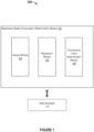
- FIGURE 1 illustrates an example system 100 including an example regression-based consumption determination module 102 configured to facilitate regression-based determination of expected energy consumption and efficient energy consumption, in accordance with an embodiment of the present disclosure.
- the regression-based consumption determination module 102 can include a feature module 104, a regression module 106, and a consumption value determination module 108.
- the example system 100 can also include at least one data source 110.
- the regression-based consumption determination module 102 can be implemented, in part or in whole, using software, hardware, or any combination thereof.
- a module can be associated with software, hardware, or any combination thereof.
- one or more functions, tasks, and/or operations of modules can be carried out or performed by software routines, software processes, hardware components, and/or any combination thereof.
- the regression-based consumption determination module 102 can be implemented as software running on one or more computing devices or systems.
- the regression-based consumption determination module 102 can be implemented within an application (e.g., app) on a computing device or system, such as a smartphone, tablet, laptop, or desktop computer of a user.
- the regression-based consumption determination module 102 can be implemented by or with an energy management platform.
- the energy platform may provide the functionality of the regression-based consumption determination module 102 as a service or through software.
- the regression-based consumption determination module 102 can be implemented within a proprietary program used by an energy provider, such as a utility company.
- the regression-based consumption determination module 102 can be implemented with a network resource, such as a website or webpage. It is contemplated that many variations are possible.
- the feature module 104 can be configured to facilitate identifying a set of features associated with at least one of a collection of residences or an energy billing period.
- features can provide or correspond to properties, characteristics, traits, and/or other information about residences and/or energy billing periods.
- the feature module 104 can utilize machine-assisted approaches (e.g., machine learning) and/or manual effort to identify which features about homes, as well as which features about energy billing periods, are useful for regression-based determination of expected energy consumption and efficient energy consumption.
- the feature module 104 can facilitate the identifying of the set of features associated with at least one of the collection of residences or the energy billing period by identifying a first subset of features and a second subset of features from the set of features.
- the first subset of features characterizes, can describe or otherwise can be associated with the collection of residences.
- the second subset of features can describe, characterize, or otherwise be associated with the energy billing period.
- the first subset of features includes but is not limited to, at least one of a residence age feature, a residence location feature, a residence area metric feature, a room quantity feature, a building type feature, a cooling system feature, a water heating feature, a space heating feature, an occupancy quantity feature, an appliance quantity feature, or a living situation feature.
- a feature value for the residence age feature for a particular residence can indicate how old the residence is.
- the feature value for the residence age feature of the residence can correspond to a year that the residence was built.
- a feature value for the residence location feature can, for example, correspond to an address, locational coordinates, or other geolocation information indicating where the residence is located and/or also can represent proximity(ies) of residents to each other.
- a feature value for the building type feature can indicate, for example, what type of building the residence is (e.g., a single-family home, a large apartment, a small apartment, a mobile home, etc.).
- a feature value for the cooling system feature can indicate, for example, whether the residence has air conditioning, whether the residence is a window unit, or whether there is an absence of a cooling system at the residence.
- a feature value for the water heating feature can indicate whether water heating for the residence utilizes electricity, natural gas, or whether another or miscellaneous type of water heating is utilized at the residence.
- a feature value for the space heating feature can, for example, indicate whether space heating for the residence utilizes electricity, natural gas, fuel oil, or whether space heating is absent at the residence.
- a feature value for the occupancy quantity feature can, for example, indicate a number of people living at the residence.
- a feature value for the appliance quantity feature can indicate what and/or how many appliances (e.g., refrigerators) are at the residence.
- the living situation feature can describe or indicate the living situation for the residence.
- a feature value for the living situation feature can indicate whether the residence is owned or rented by its resident(s). It is contemplated that there can be many variations and other possibilities.
- the second subset of features can include at least one of a heating degree days (HDD) feature, a cooling degree days (CDD) feature, or a feature that indicates an energy billing period portion.
- a feature value for the HDD feature can indicate an average HDD for a particular residence during a particular duration of time (e.g., an energy billing period).
- a feature value for the CDD feature can indicate an average CDD for the particular residence during the particular duration of time.
- a feature value for the feature that indicates the energy billing period portion can indicate, for example, a fraction or portion of the energy billing period in each of the twelve months of a year.
- the feature module 104 can also be configured to facilitate acquiring (e.g., obtaining, determining, receiving, etc.), for each residence in the collection of residences, measured energy consumption information and a plurality of feature values.
- the measured energy consumption information and the plurality of feature values can be acquired from the at least one data source 110.
- Each feature value in the plurality of feature values can correspond to a respective feature in the set of features.
- the collection of residences includes one or more residences for which information, including the plurality of feature values, is available.
- the feature module 104 can acquire information only for those residences (i.e., the collection of residences) whose information has been made available or provided by the at least one data source 110, such as an energy provider (e.g., a utility company) and/or its customer(s).
- an energy provider e.g., a utility company
- the regression-based consumption determination module 102 can receive a request to determine energy consumption values for a query residence.
- an energy provider e.g., a utility company
- a user or customer of the energy provider can make and transmit the request to determine the energy consumption values for a particular residence of interest, the query residence.
- the query residence can be associated with the user or customer.
- the user or customer can be residing at the query residence.
- the expected consumption value and the efficient consumption value for the query residence can be presented to an entity that is associated with the request, such as the energy provider and/or the customer residing at the query residence. Further, in some instances, a measured consumption value for the query residence can be presented to the entity that is associated with the request.
- the measured consumption value corresponds to an actual amount of energy consumed or used at the customer's residence (i.e., the query residence), such as an amount indicated by an energy meter reading at the customer's residence.
- the presenting of the expected consumption value, the efficient consumption value, and the measured consumption value for the customer's residence may enable the customer to better evaluate his or her energy consumption and usage.
- the presented values can enable the customer to better make decisions and/or exert effort to achieve his or her energy consumption goals. Again, many variations are possible.
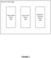
- the feature matrix module 204 can be configured to facilitate inputting the plurality of feature values for each residence into a feature matrix.
- the feature matrix module 204 can input (e.g., place, store, etc.) the plurality of feature values for each residence into a respective row, out of a set of rows, within the feature matrix.
- the output vector module 206 can be configured to facilitate inputting the measured energy consumption information for each residence into an output vector.
- the output vector module 206 can input the measured energy consumption information for each residence into a respective row, out of the set of rows, within the output vector. Accordingly, each residence can be associated with a respective row out of the set of rows.
- the plurality of feature values for a particular residence is inputted by the feature matrix module 204 into the feature matrix at a particular row, while the measured energy consumption information for the particular residence is inputted by the output vector module 206 into the output vector at the same particular row.
- the regression parameter module 208 can be configured to facilitate determining, based on the feature matrix and the output vector, the one or more parameters within the parameter vector for the regression model. Accordingly, in some cases, the training of the regression model can include the inputting of the plurality of feature values into the feature matrix by the feature matrix module 204, the inputting of the measured energy consumption information into the output vector by the output vector module 206, and the determining of the one or more parameters for the regression model by the regression parameter module 208.
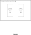
- FIGURE 3 illustrates an example consumption value determination module 302 configured to facilitate regression-based determination of expected energy consumption and efficient energy consumption, in accordance with an embodiment of the present disclosure.
- the consumption value determination module 108 of FIGURE 1 can be implemented as the example consumption value determination module 302.
- the example consumption value determination module 302 can include an expected consumption module 304 and an efficient consumption module 306.
- the consumption value determination module 302 can be configured to facilitate determining, based on the regression model, at least one expected consumption value and at least one efficient consumption value.
- the consumption value determination module 302 can utilize the expected consumption module 304 to determine the at least one expected consumption value based on the regression model and can utilize the efficient consumption module 306 to determine the at least one efficient consumption value.
- This equation can provide a basis for training and developing the regression model.
- the expected consumption module 304 can be configured to facilitate determining an expected consumption value (or "average" consumption value, as explained above) for a query residence.
- the expected consumption value for the query residence can be determined (e.g., calculated, estimated, approximated, etc.) by the expected consumption module 304 based on y exp i ⁇ ⁇ T x i .
- y exp i can represent the expected or average consumption value for the query residence as compared to a "similar" residence (as explained previously).
- x i can represent a feature vector including at least some feature values for the query residence. The at least some feature values can be provided by and acquired from the energy provider, a customer, and/or another entity associated with the query residence.
- the expected consumption module 304 can multiply a transpose of the parameter vector ( ⁇ T ) for the trained regression model with the feature vector x i including the at least some feature values for the query residence.
- the resulting product is the query residence's expected consumption value, which can correspond to a scalar value indicating an estimated or predicted amount of energy that would be expected to be consumed or used by one or more residences similar to, or having the same or similar feature values as, the query residence.
- the efficient consumption module 306 can be configured to facilitate determining an efficient consumption value for the query residence.
- the efficient consumption value for the query residence provides an estimation or approximation of an energy consumption value that should be achievable or attainable by the query residence.
- the efficient consumption value can illustrate an estimated or predicted amount of energy that is being used by one or more residences that are similar to the query residence and using energy efficiently.
- the query residence's energy consumption (e.g., measured consumption value) can already be equal to or lower than the efficient consumption value. In some cases, however, if the query residence's energy consumption is higher than the efficient consumption value, the disclosed technology can suggest how to reduce the query residence's energy consumption.
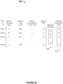
- FIGURE 4A illustrates an example representation 400 of data associated with regression-based determination of expected energy consumption and efficient energy consumption, in accordance with an embodiment of the present disclosure.
- the example representation 400 illustrates a feature matrix X 410, an output vector y 420, and a parameter vector ⁇ 430. It should be understood that the example representation 400 is provided for illustrative purposes and may not necessarily provide actual feature values, actual consumption values, etc.
- the plurality of feature values as well as the measured consumption for each residence can be provided by and/or acquired from one or more data sources, such as an energy provider (e.g., a utility company) and/or its customers (e.g., users, residents, etc.).
- Each row in the feature matrix X 410 can store the plurality of feature values for a particular residence in the collection of residences during a particular billing period.
- a corresponding row in the output vector y 420 can store the measured consumption for the particular residence during the particular billing period.
- the product of the feature matrix X 410 and the parameter vector ⁇ 430 can be equal to the output vector y 420.
- the determining of the one or more parameters (e.g., ⁇ 1 through ⁇ k ) in the parameter vector ⁇ 430 can be associated with the training of the regression model.
- the one or more parameters for the regression model can be determined or estimated.
- the regression model can be trained and developed. It follows that expected and efficient consumption values can be determined or approximated for a query residence based on the regression model.
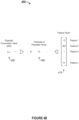
- FIGURE 4B illustrates an example representation 450 of data associated with regression-based determination of expected energy consumption, in accordance with an embodiment of the present disclosure.
- the example representation 450 illustrates a transpose ⁇ T 460 of the parameter vector ⁇ (e.g., vector 430 in FIGURE 4A ), a feature vector x i 470 including at least some feature values for a query residence i , and an expected or average consumption value y exp i 480 for the query residence.
- the example representation 450 is provided for illustrative purposes and may not necessarily provide actual feature values, actual consumption values, etc.
- the expected consumption value y exp i 480 for the query residence can be determined or estimated based on y exp i ⁇ ⁇ T x i .
- a quantity of features as well as a quantity of regression parameters can both be k, such that the product of the transpose ⁇ T 460 of the parameter vector ⁇ and the feature vector x i 470 for the query residence can result in a scalar value, the expected consumption value y exp i 480 for the query residence.
- the expected consumption value y exp i 480 for the query residence can indicate, approximate, or predict an amount of energy that is expected to be consumed or used by one or more residences similar to, or having the same or similar feature values as, the query residence. Again, many variations are possible.
- FIGURE 5 illustrates an example graph representation 500 associated with regression-based determination of expected energy consumption and efficient energy consumption, in accordance with an embodiment of the present disclosure.
- the example graph representation 500 illustrates data points that represent residences in the collection of residences. In this example, the data points are plotted with respect to a particular feature (area feature 520) associated with the data points as well as with respect to the consumption values 510 associated with the data points.
- area feature 520 associated with the data points
- the example graph representation 500 is provided for illustrative purposes, may not necessarily be drawn to scale, and may not necessarily provide actual feature values, actual consumption values, etc.
- there can be k features such that data points representing residences can be plotted with respect to their consumption values as well as with respect to each of the k features in k dimensions. Many variations are possible.
- expected consumption can be determined or estimated based on a trained regression model.
- expected consumption 530 can be determined or estimated based on a linear regression model trained using the data points associated with the residences.
- a feature value such as an area feature value x area i 550, for a particular feature (area feature 520) can be acquired for a query residence i .
- an expected or average consumption value y exp i 560 can be determined for the query residence.
- an efficient consumption value y eff i 570 can also be determined for the query residence. Again, this can be expanded to include additional features, such as a total of 30 different features. It is also contemplated that the disclosed technology can utilize any suitable number (e.g., k ) of features.
- FIGURE 6 illustrates an example presentation interface 600 associated with regression-based determination of expected energy consumption and efficient energy consumption, in accordance with an embodiment of the present disclosure.
- the example presentation interface 600 can be provided or otherwise utilized by various embodiments of the disclosed technology.
- the presentation interface 600 can be presented to and/or used by an energy provider or its customer(s).
- the presentation interface 600 can be presented to and/or used by a resident of a query residence.
- a request to determine energy consumption values for a query residence can be received.
- the presentation interface 600 can be configured to present, to an entity (e.g., utility company, user, customer, resident, etc.) that is associated with the request, the expected or average consumption value 610 for the query residence and the efficient consumption value 620 for the query residence.
- the presentation interface 600 can present, to the entity that is associated with the request, a measured consumption value 630 for the query residence.
- the presentation interface 600 can also provide one or more recommendations and/or suggestions 640 to save energy (and money).
- the consumption values e.g., measured, expected, efficient, etc.
- the consumption values can be annualized to indicate energy consumption per year.
- the consumption values can be normalized or otherwise modified to indicate energy consumption per hour, day, week, month, etc.
- the energy consumption values can be associated with electricity, gas, or a combination thereof.
- FIGURE 7A illustrates an example method 700 associated with regression-based determination of expected energy consumption and efficient energy consumption, in accordance with an embodiment of the present disclosure. It should be understood that there can be additional, fewer, or alternative steps performed in similar or alternative orders, or in parallel, within the scope of the various embodiments unless otherwise stated.
- the example method 700 can identify a set of features associated with at least one of a collection of residences or an energy billing period.
- the example method 700 can acquire, for each residence in the collection of residences, measured energy consumption information and a plurality of feature values. Each feature value in the plurality of feature values can correspond to a respective feature in the set of features.
- the example method 700 can train a regression model based on the measured energy consumption information and the plurality of features values for each residence in the collection of residences.
- the example method 700 can determine, based on the regression model, at least one expected consumption value and at least one efficient consumption value.
- FIGURE 7B illustrates an example method 750 associated with regression-based determination of expected energy consumption and efficient energy consumption, in accordance with an embodiment of the present disclosure. Again, it should be appreciated that there can be additional, fewer, or alternative steps performed in similar or alternative orders, or in parallel, within the scope of the various embodiments unless otherwise stated.
- the example method 750 can receive a request to determine energy consumption values for a query residence.
- the example method 750 can acquire at least some (e.g., all) feature values for the query residence.
- the example method 750 can determine an expected consumption value for the query residence based on the regression model and the at least some feature values for the query residence.
- the example method 750 can determine, based on the expected consumption value for the query residence, an efficient consumption value for the query residence.
- the example regression-based consumption determination module 102 of FIGURE 1 can be implemented, in part or in whole, as software, hardware, or any combination thereof.
- the regression-based consumption determination module 102 can be implemented with an energy management platform, such as the energy management platform 802 of FIGURE 8 and/or the energy management platform 902 of FIGURE 9 . Again, it is contemplated that there can be many variations and other possibilities.
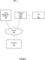
- FIGURE 8 illustrates an example environment 800 for energy management, in accordance with an embodiment of the present disclosure.
- the environment 800 includes an energy management platform 802, external data sources 8041-n, an enterprise 806, and a network 808.
- the energy management platform 802 can provide functionality to allow the enterprise 806 to track, analyze, and optimize energy usage of the enterprise 806.
- the energy management platform 802 may constitute an analytics platform.
- the analytics platform may handle data management, multi-layered analysis, and data visualization capabilities for all applications of the energy management platform 802.
- the analytics platform may be specifically designed to process and analyze significant volumes of frequently updated data while maintaining high performance levels.
- the energy management platform 802 may communicate with the enterprise 806 through user interfaces (Uls) presented by the energy management platform 802 for the enterprise 806.
- the Uls may provide information to the enterprise 806 and receive information from the enterprise 806.
- the energy management platform 802 may communicate with the external data sources 8041-n through APIs and other communication interfaces. Communications involving the energy management platform 802, the external data sources 8041-n, and the enterprise 806 are discussed in more detail herein.
- the energy management platform 802 may be implemented as a computer system, such as a server or series of servers and other hardware (e.g., applications servers, analytic computational servers, database servers, data integrator servers, network infrastructure (e.g., firewalls, routers, communication nodes)).
- the servers may be arranged as a server farm or cluster.
- Embodiments of the present disclosure may be implemented on the server side, on the client side, or a combination of both.
- embodiments of the present disclosure may be implemented by one or more servers of the energy management platform 802.
- embodiments of the present disclosure may be implemented by a combination of servers of the energy management platform 802 and a computer system of the enterprise 806.
- the external data sources 8041-n may represent a multitude of possible sources of data relevant to energy management analysis.
- the external data sources 8041-n may include, for example, grid and utility operational systems, meter data management (MDM) systems, customer information systems (CIS), billing systems, utility customer systems, utility enterprise systems, utility energy conservation measures, and rebate databases.
- the external data sources 8041-n also may include, for example, building characteristic systems, weather data sources, third-party property management systems, and industry-standard benchmark databases.
- the enterprise 806 may represent a user (e.g., customer) of the energy management platform 802.
- the enterprise 806 may include any private or public concern, such as large companies, small and medium businesses, households, individuals, governing bodies, government agencies, non-governmental organizations, nonprofits, etc.
- the enterprise 806 may include energy providers and suppliers (e.g., utilities), energy service companies (ESCOs), and energy consumers.
- the enterprise 806 may be associated with one or many facilities distributed over many geographic locations.
- the enterprise 806 may be associated with any purpose, industry, or other type of profile.
- the network 808 may use standard communications technologies and protocols.
- the network 808 may include links using technologies such as Ethernet, 802.11, worldwide interoperability for microwave access (WiMAX), 3G, 4G, CDMA, GSM, LTE, digital subscriber line (DSL), etc.
- the networking protocols used on the network 808 may include multiprotocol label switching (MPLS), transmission control protocol/Internet protocol (TCP/IP), User Datagram Protocol (UDP), hypertext transport protocol (HTTP), simple mail transfer protocol (SMTP), file transfer protocol (FTP), and the like.
- the data exchanged over the network 808 may be represented using technologies and/or formats including hypertext markup language (HTML) and extensible markup language (XML).
- all or some links may be encrypted using conventional encryption technologies such as secure sockets layer (SSL), transport layer security (TLS), and Internet Protocol security (IPsec).
- SSL secure sockets layer
- TLS transport layer security
- IPsec Internet Protocol security
- each of the energy management platform 802, the external data sources 8041-n, and the enterprise 806 may be implemented as a computer system (or device).
- the computer system (or device) may include one or more machines, each of which may be implemented as machine 1100 of FIGURE 11 , which is described in further detail herein.
- FIGURE 9 illustrates an example energy management platform 902, in accordance with an embodiment of the present disclosure.
- the example energy management platform 902 can be implemented as the energy management platform 802 of FIGURE 8 .
- the energy management platform 902 may include a data management module 910, applications servers 912, relational databases 914, and key/value stores 916.
- the energy management platform 902 can also include a regression-based consumption determination module (e.g., the regression-based consumption determination module 102 of FIGURE 1 ).
- the data management module 910 may support the capability to automatically and dynamically scale a network of computing resources for the energy management platform 902 according to demand on the energy management platform 902.
- the dynamic scaling supported by the data management module 910 may include the capability to provision additional computing resources (or nodes) to accommodate increasing computing demand.
- the data management module 910 may include the capability to release computing resources to accommodate decreasing computing demand.
- the data management module 910 may include one or more action(s) 918, a queue 920, a dispatcher 922, a resource manager 924, and a cluster manager 926.
- the actions 918 may represent the tasks that are to be performed in response to requests that are provided to the energy management platform 902. Each of the actions 918 may represent a unit of work to be performed by the applications servers 912. The actions 918 may be associated with data types and bound to engines (or modules). The requests may relate to any task supported by the energy management platform 902. For example, the request may relate to, for example, analytic processing, loading energy-related data, retrieving an energy star reading, retrieving benchmark data, etc. The actions 918 are provided to the action queue 920.
- the action queue 920 may receive each of the actions 918.
- the action queue 920 may be a distributed task queue and represents work that is to be routed to an appropriate computing resource and then performed.
- the dispatcher 922 may associate and hand-off a queued action to an engine that will execute the action.
- the dispatcher 922 may control routing of each queued action to a particular one of the applications servers 912 based on load balancing and other optimization considerations.
- the dispatcher 922 may receive an instruction from the resource manager 924 to provision new nodes when the current computing resources are at or above a threshold capacity.
- the dispatcher 922 also may receive an instruction from the resource manager to release nodes when the current computing resources are at or below a threshold capacity.
- the dispatcher 922 accordingly may instruct the cluster manager 926 to dynamically provision new nodes or release existing nodes based on demand for computing resources.
- the nodes may be computing nodes or storage nodes in connection with the applications servers 912, the relational databases 914, and the key/value stores 916.
- the resource manager 924 may monitor the action queue 920.
- the resource manager 924 also may monitor the current load on the applications servers 912 to determine the availability of resources to execute the queued actions. Based on the monitoring, the resource manager may communicate, through the dispatcher 922, with the cluster manager 926 to request dynamic allocation and de-allocation of nodes.
- the cluster manager 926 may be a distributed entity that manages all of the nodes of the applications servers 912.
- the cluster manager 926 may dynamically provision new nodes or release existing nodes based on demand for computing resources.
- the cluster manager 926 may implement a group membership services protocol.
- the cluster manager 926 also may perform a task monitoring function.
- the task monitoring function may involve tracking resource usage, such as CPU utilization, the amount of data read/written, storage size, etc.
- the applications servers 912 may perform processes that manage or host analytic server execution, data requests, etc.
- the engines provided by the energy management platform 902, such as the engines that perform data services, batch processing, stream services, may be hosted within the applications servers 912. The engines are discussed in more detail herein.
- the applications servers 912 may be part of a computer cluster of a plurality of loosely or tightly connected computers that are coordinated to work as a system in performing the services and applications of the energy management platform 902.
- the nodes (e.g., servers) of the cluster may be connected to each other through fast local area networks ("LAN"), with each node running its own instance of an operating system.
- the applications servers 912 may be implemented as a computer cluster to improve performance and availability over that of a single computer, while typically being more cost-effective than single computers of comparable speed or availability.
- the applications servers 912 may be software, hardware, or a combination of both.
- the relational databases 914 may maintain various data supporting the energy management platform 902.
- non-time series data may be stored in the relational databases 914, as discussed in more detail herein.
- the key/value stores 916 may maintain various data supporting the energy management platform 902.
- time series data e.g., meter readings, meter events, etc.
- the key/value stores 916 may be implemented with Apache Cassandra, an open source distributed database management system designed to handle large amounts of data across a multitude of commodity servers.
- other database management systems for key/value stores may be used.
- one or more of the applications servers 912, the relational databases 914, and the key/value stores 916 may be implemented by the entity that owns, maintains, or controls the energy management platform 902.
- one or more of the applications servers 912, the relational databases 914, and the key/value stores 916 may be implemented by a third party that may provide a computing environment for lease to the entity that owns, maintains, or controls the energy management platform 902.
- the applications servers 912, the relational databases 914, and the key/value stores 916 implemented by the third party may communicate with the energy management platform 902 through a network, such as the network 808 of FIGURE 8 .
- the computing environment provided by the third party for the entity that owns, maintains, or controls the energy management platform 902 may be a cloud computing platform that allows the entity that owns, maintains, or controls the energy management platform 902 to rent virtual computers on which to run its own computer applications.
- Such applications may include, for example, the applications performed by the applications servers 912, as discussed in more detail herein.
- the computing environment may allow a scalable deployment of applications by providing a web service through which the entity that owns, maintains, or controls the energy management platform 902 can boot a virtual appliance used to create a virtual machine containing any software desired.
- the entity that owns, maintains, or controls the energy management platform 902 may create, launch, and terminate server instances as needed, paying based on time usage time, data usage, or any combination of these or other factors.
- the ability to provision and release computing resources in this manner supports the ability of the energy management platform 902 to dynamically scale according to the demand on the energy management platform 902.
- FIGURE 10 illustrates an example applications server 1000 of an energy management platform, in accordance with an embodiment of the present disclosure.
- the applications server 1000 includes a data integrator (data loading) module 1002, an integration services module 1004, a data services module 1006, a computational services module 1008, a stream analytic services module 1010, a batch parallel processing analytic services module 1012, a normalization module 1014, an analytics container 1016, a data model 1018, and a user interface (Ul) services module 1024.
- the applications server 1000 can also include a regression-based consumption determination module 1030.
- the regression-based consumption determination module 1030 can be implemented as the regression-based consumption determination module 102 of FIGURE 1 .
- the analytics platform supported by the applications server 1000 includes multiple services that each handles a specific data management or analysis capability.
- the services include the data integrator module 1002, the integration services module 1004, the data services module 1006, the computational services module 1008, the stream analytic services module 1010, batch parallel processing analytic services module 1012, and the UI services module 1024. All or some services within the analytics platform may be modular and accordingly architected specifically to execute their respective capabilities for large data volumes and at high speed.
- the services may be optimized in software for high performance distributed computing over a computer cluster including the applications servers 912.
- FIGURE 11 illustrates an example machine 1100 within which a set of instructions for causing the machine to perform one or more of the embodiments described herein can be executed, in accordance with an embodiment of the present disclosure.
- the machine may be connected (e.g., networked) to other machines.
- the machine may operate in the capacity of a server or a client machine in a client-server network environment, or as a peer machine in a peer-to-peer (or distributed) network environment.
- the machine 1100 also includes a video display 1110, an alphanumeric input device 1112 (e.g., a keyboard), a cursor control device 1114 (e.g., a mouse), a drive unit 1116, a signal generation device 1118 (e.g., a speaker) and a network interface device 1120.
- a video display 1110 an alphanumeric input device 1112 (e.g., a keyboard), a cursor control device 1114 (e.g., a mouse), a drive unit 1116, a signal generation device 1118 (e.g., a speaker) and a network interface device 1120.
- the video display 1110 includes a touch sensitive screen for user input.
- the touch sensitive screen is used instead of a keyboard and mouse.
- the disk drive unit 1116 includes a machine-readable medium 1122 on which is stored one or more sets of instructions 1124 (e.g., software) embodying any one or more of the methodologies or functions described herein.
- the instructions 1124 can also reside, completely or at least partially, within the main memory 1104 and/or within the processor 1102 during execution thereof by the computer system 1100.
- the instructions 1124 can further be transmitted or received over a network 1140 via the network interface device 1120.
- the machine-readable medium 1122 also includes a database 1125.
- Volatile RAM may be implemented as dynamic RAM (DRAM), which requires power continually in order to refresh or maintain the data in the memory.
- Non- volatile memory is typically a magnetic hard drive, a magnetic optical drive, an optical drive (e.g., a DVD RAM), or other type of memory system that maintains data even after power is removed from the system.
- the non-volatile memory may also be a random access memory.
- the non-volatile memory can be a local device coupled directly to the rest of the components in the data processing system.
- a non-volatile memory that is remote from the system such as a network storage device coupled to any of the computer systems described herein through a network interface such as a modem or Ethernet interface, can also be used.
- machine-readable medium 1122 is shown in an exemplary embodiment to be a single medium, the term “machine-readable medium” should be taken to include a single medium or multiple media (e.g., a centralized or distributed database, and/or associated caches and servers) that store the one or more sets of instructions.
- the term “machine-readable medium” shall also be taken to include any medium that is capable of storing, encoding or carrying a set of instructions for execution by the machine and that cause the machine to perform any one or more of the methodologies of the present disclosure.
- the term “machine-readable medium” shall accordingly be taken to include, but not be limited to, solid-state memories, optical and magnetic media, and carrier wave signals.
- storage module as used herein may be implemented using a machine-readable medium.
- routines executed to implement the embodiments of the present disclosure can be implemented as part of an operating system or a specific application, component, program, object, module or sequence of instructions referred to as "programs" or "applications".
- programs or “applications”.
- one or more programs or applications can be used to execute specific processes described herein.
- the programs or applications typically comprise one or more instructions set at various times in various memory and storage devices in the machine and that, when read and executed by one or more processors, cause the machine to perform operations to execute elements involving the various aspects of the embodiments described herein.
- the executable routines and data may be stored in various places, including, for example, ROM, volatile RAM, non-volatile memory, and/or cache. Portions of these routines and/or data may be stored in any one of these storage devices. Further, the routines and data can be obtained from centralized servers or peer-to-peer networks. Different portions of the routines and data can be obtained from different centralized servers and/or peer-to-peer networks at different times and in different communication sessions, or in a same communication session. The routines and data can be obtained in entirety prior to the execution of the applications. Alternatively, portions of the routines and data can be obtained dynamically, just in time, when needed for execution. Thus, it is not required that the routines and data be on a machine-readable medium in entirety at a particular instance of time.
- machine-readable media include, but are not limited to, recordable type media such as volatile and non-volatile memory devices, floppy and other removable disks, hard disk drives, optical disks (e.g., Compact Disk Read-Only Memory (CD ROMS), Digital Versatile Disks, (DVDs), etc.), among others, and transmission type media such as digital and analog communication links.
- recordable type media such as volatile and non-volatile memory devices, floppy and other removable disks, hard disk drives, optical disks (e.g., Compact Disk Read-Only Memory (CD ROMS), Digital Versatile Disks, (DVDs), etc.
- CD ROMS Compact Disk Read-Only Memory
- DVDs Digital Versatile Disks
- the embodiments described herein can be implemented using special purpose circuitry, with or without software instructions, such as using Application-Specific Integrated Circuit (ASIC) or Field-Programmable Gate Array (FPGA).
- ASIC Application-Specific Integrated Circuit
- FPGA Field-Programmable Gate Array
- Embodiments can be implemented using hardwired circuitry without software instructions, or in combination with software instructions. Thus, the techniques are limited neither to any specific combination of hardware circuitry and software, nor to any particular source for the instructions executed by the data processing system.
- modules, structures, processes, features, and devices are shown in block diagram form in order to avoid obscuring the description.
- functional block diagrams and flow diagrams are shown to represent data and logic flows.
- the components of block diagrams and flow diagrams may be variously combined, separated, removed, reordered, and replaced in a manner other than as expressly described and depicted herein.
- references in this specification to "one embodiment”, “an embodiment”, “other embodiments”, “another embodiment”, or the like means that a particular feature, design, structure, or characteristic described in connection with the embodiment is included in at least one embodiment of the disclosure.
- the appearances of, for example, the phrases “according to an embodiment”, “in one embodiment”, “in an embodiment”, or “in another embodiment” in various places in the specification are not necessarily all referring to the same embodiment, nor are separate or alternative embodiments mutually exclusive of other embodiments.
- various features are described, which may be variously combined and included in some embodiments but also variously omitted in other embodiments.
- various features are described which may be preferences or requirements for some embodiments but not other embodiments.
Landscapes
- Business, Economics & Management (AREA)
- Engineering & Computer Science (AREA)
- Economics (AREA)
- Human Resources & Organizations (AREA)
- Strategic Management (AREA)
- General Physics & Mathematics (AREA)
- Physics & Mathematics (AREA)
- Entrepreneurship & Innovation (AREA)
- General Business, Economics & Management (AREA)
- Health & Medical Sciences (AREA)
- Marketing (AREA)
- Tourism & Hospitality (AREA)
- Theoretical Computer Science (AREA)
- Development Economics (AREA)
- Public Health (AREA)
- Water Supply & Treatment (AREA)
- General Health & Medical Sciences (AREA)
- Educational Administration (AREA)
- Primary Health Care (AREA)
- Game Theory and Decision Science (AREA)
- Operations Research (AREA)
- Quality & Reliability (AREA)
- Management, Administration, Business Operations System, And Electronic Commerce (AREA)
- Remote Monitoring And Control Of Power-Distribution Networks (AREA)
- Power Engineering (AREA)
Claims (13)
- Computerimplementiertes Verfahren zur Bestimmung des Energieverbrauchs für einen Wohnsitz, wobei das Verfahren Folgendes umfasst:(a) Erfassen eines Satzes von ausgewählten Merkmalen, die mit einer Sammlung von Wohnsitzen assoziiert sind, wobei der Satz von ausgewählten Merkmalen basierend auf seinem potenziellen Einfluss auf den Energieverbrauch der Sammlung von Wohnsitzen erfasst wird,(b) Organisieren des Satzes von ausgewählten Merkmalen in einen ersten Teilsatz und einen zweiten Teilsatz, wobei der erste Teilsatz von Merkmalen die Sammlung von Wohnsitzen kennzeichnet und zumindest eines von einem Wohnsitzaltermerkmal, einem Wohnsitzortsmerkmal, einem Wohnsitzflächenmetrikmerkmal, einem Raumquantitätsmerkmal, einem Gebäudetypmerkmal, einem Kühlsystemmerkmal, einem Wassererwärmungsmerkmal, einem Raumerwärmungsmerkmal, einem Belegungsquantitätsmerkmal, einem Gerätequantitätsmerkmal und einem Lebenssituationsmerkmal beinhaltet und der zweite Teilsatz von Merkmalen Erwärmen und/oder Kühlen der Sammlung von Wohnsitzen während eines Zeitraums beschreibt;(c) Erfassen, für jeden Wohnsitz in der Sammlung von Wohnsitzen, von Daten, die einen gemessenen Verbrauchswert und eine Vielzahl von Merkmalswerten umfassen, wobei jeder Merkmalswert in der Vielzahl von Merkmalswerten einem jeweiligen Merkmal in dem Satz von ausgewählten Merkmalen entspricht, wobei der gemessene Verbrauchswert für jeden Wohnsitz einer Menge an Energie entspricht, die an jedem Wohnsitz verbraucht wird, und Energiezählerablesungen von Energiezählern für die Sammlung von Wohnsitzen umfasst,(d) Organisieren der Vielzahl von Merkmalswerten in eine erste Gruppe und eine zweite Gruppe, wobei jeder Merkmalswert in der ersten Gruppe einem jeweiligen Merkmal in dem ersten Teilsatz entspricht und jeder Merkmalswert in der zweiten Gruppe einem jeweiligen Merkmal in dem zweiten Teilsatz entspricht,(e) Trainieren eines Regressionsmodells basierend zumindest auf den gemessenen Verbrauchswerten und der Vielzahl von Merkmalswerten für jeden Wohnsitz in der Sammlung von Wohnsitzen,(f) Erfassen, für einen Abfragewohnsitz, einer Vielzahl von Merkmalswerten, die mit dem Abfragewohnsitz assoziiert ist, wobei der Abfragewohnsitz kein Wohnsitz in der Sammlung von Wohnsitzen ist; und(g) Verwenden des Regressionsmodells, um zumindest einen erwarteten Verbrauchswert und zumindest einen effizienten Verbrauchswert für den Abfragewohnsitz zu bestimmen.
- Computerimplementiertes Verfahren nach Anspruch 1, ferner umfassend, vor (f), Empfangen einer Anforderung zum Bestimmen des zumindest einen erwarteten Verbrauchswertes oder des zumindest einen effizienten Verbrauchswertes für den Abfragewohnsitz.
- Computerimplementiertes Verfahren nach Anspruch 2, ferner umfassend (h), Bereitstellen des zumindest einen erwarteten Verbrauchswertes oder des zumindest einen effizienten Verbrauchswertes für den Abfragewohnsitz, der in (g) bestimmt wird, an eine Entität, die mit der Anforderung assoziiert ist.
- Computerimplementiertes Verfahren nach Anspruch 1, wobei die Daten in (c) von zumindest einer Datenquelle, die einen Energieversorger umfasst, oder einem Bewohner des Abfragewohnsitzes erfasst werden.
- Computerimplementiertes Verfahren nach Anspruch 1, wobei das Trainieren des Regressionsmodells Folgendes umfasst:(a) Speichern der Vielzahl von Merkmalswerten für jeden Wohnsitz in der Sammlung von Wohnsitzen in einer jeweiligen Reihe aus einem Satz von Reihen innerhalb einer Merkmalsmatrix;(b) Speichern der gemessenen Verbrauchswerte für jeden Wohnsitz in der Sammlung von Wohnsitzen in einer jeweiligen Reihe aus dem Satz von Reihen innerhalb eines Ausgabevektors; und(c) Bestimmen, basierend auf der Merkmalsmatrix und dem Ausgabevektor, von einem oder mehreren Parametern innerhalb eines Parametervektors für das Regressionsmodell.
- Computerimplementiertes Verfahren nach Anspruch 5, wobei ein Produkt der Merkmalsmatrix und des Parametervektors gleich dem Ausgabevektor ist.
- Computerimplementiertes Verfahren nach Anspruch 5, wobei X die Merkmalsmatrix darstellt, Y den Ausgabevektor darstellt und θ den einen oder die mehreren Parameter in dem Parametervektor darstellt, und wobei das Regressionsmodell auf die Formel θ = (XTX)-1XTY trainiert ist.
- Computerimplementiertes Verfahren nach Anspruch 5, wobei das Bestimmen des zumindest einen erwarteten Verbrauchswertes Multiplizieren der Vielzahl von Merkmalswerten, die mit dem Abfragewohnsitz assoziiert ist, mit dem einen oder den mehreren Parametern in dem Parametervektor umfasst.
- Computerimplementiertes Verfahren nach Anspruch 8, wobei das Bestimmen des zumindest einen effizienten Verbrauchswertes Subtrahieren eines Standardfehlers von dem zumindest einen erwarteten Verbrauchswert umfasst.
- Computerimplementiertes Verfahren nach Anspruch 1, ferner umfassend (h), Erzeugen von einer oder mehreren Empfehlungen, um Energieverbrauch zu reduzieren, wenn der zumindest eine erwartete Verbrauchswert höher als der zumindest eine effiziente Verbrauchswert für den Abfragewohnsitz ist.
- Computerimplementiertes Verfahren nach Anspruch 10, wobei die eine oder mehreren Ressourcen elektrizitäts- oder gasbezogene Ressourcen umfassen.
- System zur Bestimmung des Energieverbrauchs für einen Wohnsitz, wobei das System Folgendes umfasst:zumindest einen Prozessor; undeinen Speicher, der Anweisungen speichert, die, wenn durch den zumindest einen Prozessor ausgeführt, bewirken, dass das System Folgendes durchführt:(a) Erfassen eines Satzes von ausgewählten Merkmalen, die mit einer Sammlung von Wohnsitzen assoziiert sind, wobei der Satz von ausgewählten Merkmalen basierend auf seinem potenziellen Einfluss auf den Energieverbrauch der Sammlung von Wohnsitzen erfasst wird,(b) Organisieren des Satzes von ausgewählten Merkmalen in einen ersten Teilsatz und einen zweiten Teilsatz, wobei der erste Teilsatz von Merkmalen die Sammlung von Wohnsitzen kennzeichnet und zumindest eines von einem Wohnsitzaltermerkmal, einem Wohnsitzortsmerkmal, einem Wohnsitzflächenmetrikmerkmal, einem Raumquantitätsmerkmal, einem Gebäudetypmerkmal, einem Kühlsystemmerkmal, einem Wassererwärmungsmerkmal, einem Raumerwärmungsmerkmal, einem Belegungsquantitätsmerkmal, einem Gerätequantitätsmerkmal und einem Lebenssituationsmerkmal beinhaltet und der zweite Teilsatz von Merkmalen Erwärmen und/oder Kühlen der Sammlung von Wohnsitzen während eines Zeitraums beschreibt;(c) Erfassen, für jeden Wohnsitz in der Sammlung von Wohnsitzen, von Daten, die einen gemessenen Verbrauchswert und eine Vielzahl von Merkmalswerten umfassen, wobei jeder Merkmalswert in der Vielzahl von Merkmalswerten einem jeweiligen Merkmal in dem Satz von ausgewählten Merkmalen entspricht, wobei der gemessene Verbrauchswert für jeden Wohnsitz einer Menge an Energie entspricht, die an jedem Wohnsitz verbraucht wird, und Energiezählerablesungen umfasst, die von Energiezählern von der Sammlung von Wohnsitzen empfangen werden;(d) Organisieren der Vielzahl von Merkmalswerten in eine erste Gruppe und eine zweite Gruppe, wobei jeder Merkmalswert in der ersten Gruppe einem jeweiligen Merkmal in dem ersten Teilsatz entspricht und jeder Merkmalswert in der zweiten Gruppe einem jeweiligen Merkmal in dem zweiten Teilsatz entspricht,(e) Trainieren eines Regressionsmodells basierend zumindest auf den gemessenen Verbrauchswerten und der Vielzahl von Merkmalswerten für jeden Wohnsitz in der Sammlung von Wohnsitzen,(f) Erfassen, für einen Abfragewohnsitz, einer Vielzahl von Merkmalswerten, die mit dem Abfragewohnsitz assoziiert ist, wobei der Abfragewohnsitz kein Wohnsitz in der Sammlung von Wohnsitzen ist; und(g) Verwenden des Regressionsmodells, um zumindest einen erwarteten Verbrauchswert und zumindest einen effizienten Verbrauchswert für die Abfrage zu bestimmen.
- Nichtflüchtiges computerlesbares Speichermedium, das Anweisungen beinhaltet, die, wenn durch zumindest einen Prozessor eines Rechensystems ausgeführt, bewirken, dass das Rechensystem Folgendes durchführt:(a) Erfassen eines Satzes von ausgewählten Merkmalen, die mit einer Sammlung von Wohnsitzen assoziiert sind, wobei der Satz von ausgewählten Merkmalen basierend auf seinem potenziellen Einfluss auf den Energieverbrauch der Sammlung von Wohnsitzen erfasst wird,(b) Organisieren des Satzes von ausgewählten Merkmalen in einen ersten Teilsatz und einen zweiten Teilsatz, wobei der erste Teilsatz von Merkmalen die Sammlung von Wohnsitzen kennzeichnet und zumindest eines von einem Wohnsitzaltermerkmal, einem Wohnsitzortsmerkmal, einem Wohnsitzflächenmetrikmerkmal, einem Raumquantitätsmerkmal, einem Gebäudetypmerkmal, einem Kühlsystemmerkmal, einem Wassererwärmungsmerkmal, einem Raumerwärmungsmerkmal, einem Belegungsquantitätsmerkmal, einem Gerätequantitätsmerkmal und einem Lebenssituationsmerkmal beinhaltet und der zweite Teilsatz von Merkmalen Erwärmen und/oder Kühlen der Sammlung von Wohnsitzen während eines Zeitraums beschreibt;(c) Erfassen, für jeden Wohnsitz in der Sammlung von Wohnsitzen, von Daten, die einen gemessenen Verbrauchswert und eine Vielzahl von Merkmalswerten umfassen, wobei jeder Merkmalswert in der Vielzahl von Merkmalswerten einem jeweiligen Merkmal in dem Satz von ausgewählten Merkmalen entspricht, wobei der gemessene Verbrauchswert für jeden Wohnsitz einer Menge an Energie entspricht, die an jedem Wohnsitz verbraucht wird, und Energiezählerablesungen von Energiezählern für die Sammlung von Wohnsitzen umfasst,(d) Organisieren der Vielzahl von Merkmalswerten in eine erste Gruppe und eine zweite Gruppe, wobei jeder Merkmalswert in der ersten Gruppe einem jeweiligen Merkmal in dem ersten Teilsatz entspricht und jeder Merkmalswert in der zweiten Gruppe einem jeweiligen Merkmal in dem zweiten Teilsatz entspricht,(e) Trainieren eines Regressionsmodells basierend zumindest auf den gemessenen Verbrauchswerten und der Vielzahl von Merkmalswerten für jeden Wohnsitz in der Sammlung von Wohnsitzen,(f) Erfassen, für einen Abfragewohnsitz, einer Vielzahl von Merkmalswerten, die mit dem Abfragewohnsitz assoziiert ist, wobei der Abfragewohnsitz kein Wohnsitz in der Sammlung von Wohnsitzen ist; und(g) Verwenden des Regressionsmodells, um zumindest einen erwarteten Verbrauchswert und zumindest einen effizienten Verbrauchswert für den Abfragewohnsitz zu bestimmen.
Priority Applications (1)
| Application Number | Priority Date | Filing Date | Title |
|---|---|---|---|
| EP25152025.0A EP4530964A3 (de) | 2015-02-12 | 2016-02-12 | Systeme und verfahren zur regressionsbasierten bestimmung des erwarteten energieverbrauchs und des effizienten energieverbrauchs |
Applications Claiming Priority (3)
| Application Number | Priority Date | Filing Date | Title |
|---|---|---|---|
| US14/621,228 US10346933B2 (en) | 2015-02-12 | 2015-02-12 | Systems and methods for regression-based determination of expected energy consumption and efficient energy consumption |
| PCT/US2016/017778 WO2016130934A1 (en) | 2015-02-12 | 2016-02-12 | Systems and methods for regression-based determination of expected energy consumption and efficient energy consumption |
| EP16749971.4A EP3283935A4 (de) | 2015-02-12 | 2016-02-12 | Systeme und verfahren zur regressionsbasierten bestimmung des erwarteten energieverbrauchs und des effizienten energieverbrauchs |
Related Parent Applications (1)
| Application Number | Title | Priority Date | Filing Date |
|---|---|---|---|
| EP16749971.4A Division EP3283935A4 (de) | 2015-02-12 | 2016-02-12 | Systeme und verfahren zur regressionsbasierten bestimmung des erwarteten energieverbrauchs und des effizienten energieverbrauchs |
Related Child Applications (2)
| Application Number | Title | Priority Date | Filing Date |
|---|---|---|---|
| EP25152025.0A Division EP4530964A3 (de) | 2015-02-12 | 2016-02-12 | Systeme und verfahren zur regressionsbasierten bestimmung des erwarteten energieverbrauchs und des effizienten energieverbrauchs |
| EP25152025.0A Division-Into EP4530964A3 (de) | 2015-02-12 | 2016-02-12 | Systeme und verfahren zur regressionsbasierten bestimmung des erwarteten energieverbrauchs und des effizienten energieverbrauchs |
Publications (2)
| Publication Number | Publication Date |
|---|---|
| EP4016410A1 EP4016410A1 (de) | 2022-06-22 |
| EP4016410B1 true EP4016410B1 (de) | 2025-02-26 |
Family
ID=56615729
Family Applications (3)
| Application Number | Title | Priority Date | Filing Date |
|---|---|---|---|
| EP16749971.4A Ceased EP3283935A4 (de) | 2015-02-12 | 2016-02-12 | Systeme und verfahren zur regressionsbasierten bestimmung des erwarteten energieverbrauchs und des effizienten energieverbrauchs |
| EP21209783.6A Active EP4016410B1 (de) | 2015-02-12 | 2016-02-12 | Systeme und verfahren zur regressionsbasierten bestimmung des erwarteten energieverbrauchs und des effizienten energieverbrauchs |
| EP25152025.0A Pending EP4530964A3 (de) | 2015-02-12 | 2016-02-12 | Systeme und verfahren zur regressionsbasierten bestimmung des erwarteten energieverbrauchs und des effizienten energieverbrauchs |
Family Applications Before (1)
| Application Number | Title | Priority Date | Filing Date |
|---|---|---|---|
| EP16749971.4A Ceased EP3283935A4 (de) | 2015-02-12 | 2016-02-12 | Systeme und verfahren zur regressionsbasierten bestimmung des erwarteten energieverbrauchs und des effizienten energieverbrauchs |
Family Applications After (1)
| Application Number | Title | Priority Date | Filing Date |
|---|---|---|---|
| EP25152025.0A Pending EP4530964A3 (de) | 2015-02-12 | 2016-02-12 | Systeme und verfahren zur regressionsbasierten bestimmung des erwarteten energieverbrauchs und des effizienten energieverbrauchs |
Country Status (5)
| Country | Link |
|---|---|
| US (4) | US10346933B2 (de) |
| EP (3) | EP3283935A4 (de) |
| CA (1) | CA2991189C (de) |
| ES (1) | ES3019358T3 (de) |
| WO (1) | WO2016130934A1 (de) |
Families Citing this family (6)
| Publication number | Priority date | Publication date | Assignee | Title |
|---|---|---|---|---|
| WO2013163460A1 (en) | 2012-04-25 | 2013-10-31 | Myenersave, Inc. | Energy disaggregation techniques for low resolution whole-house energy consumption data |
| WO2016037013A1 (en) | 2014-09-04 | 2016-03-10 | Bidgely Inc. | Systems and methods for optimizing energy usage using energy disaggregation data and time of use information |
| US10346933B2 (en) | 2015-02-12 | 2019-07-09 | C3 Iot, Inc. | Systems and methods for regression-based determination of expected energy consumption and efficient energy consumption |
| US10657110B2 (en) | 2017-01-23 | 2020-05-19 | Bidgely Inc. | Systems and methods for disaggregating appliance loads |
| US20190050430A1 (en) * | 2017-01-23 | 2019-02-14 | Bidgely Inc. | Systems and Methods for Disaggregating Appliance Loads |
| DE102017204176A1 (de) * | 2017-03-14 | 2018-09-20 | Bayerische Motoren Werke Aktiengesellschaft | Verfahren zum Aggregieren von Betriebswerten einer Vielzahl örtlich verteilter Betriebseinheiten sowie Überwachungsvorrichtung zum Durchführen des Verfahrens |
Citations (5)
| Publication number | Priority date | Publication date | Assignee | Title |
|---|---|---|---|---|
| JP2006079426A (ja) | 2004-09-10 | 2006-03-23 | Shimizu Corp | エネルギー消費量診断装置及びエネルギー消費量診断方法 |
| US20100042453A1 (en) | 2008-08-12 | 2010-02-18 | Efficiency 2.0, LLC. | Methods and apparatus for greenhouse gas footprint monitoring |
| US20120278051A1 (en) | 2011-04-29 | 2012-11-01 | International Business Machines Corporation | Anomaly detection, forecasting and root cause analysis of energy consumption for a portfolio of buildings using multi-step statistical modeling |
| US20140142905A1 (en) | 2012-11-16 | 2014-05-22 | Johnson Controls Technology Company | Systems and methods for building energy use benchmarking |
| US20140351018A1 (en) | 2013-05-24 | 2014-11-27 | Mastercard International Incorporated | System and method for benchmarking energy usage |
Family Cites Families (18)
| Publication number | Priority date | Publication date | Assignee | Title |
|---|---|---|---|---|
| US1034693A (en) | 1911-07-03 | 1912-08-06 | Zenas N Cox | Mine-door. |
| US8433530B2 (en) * | 2008-09-18 | 2013-04-30 | ThinkEco, Inc. | System and method for monitoring and management of utility usage |
| US9606520B2 (en) * | 2009-06-22 | 2017-03-28 | Johnson Controls Technology Company | Automated fault detection and diagnostics in a building management system |
| US9196009B2 (en) * | 2009-06-22 | 2015-11-24 | Johnson Controls Technology Company | Systems and methods for detecting changes in energy usage in a building |
| US8855830B2 (en) * | 2009-08-21 | 2014-10-07 | Allure Energy, Inc. | Energy management system and method |
| CN105976258B (zh) * | 2010-04-08 | 2019-12-10 | 能源管理公司 | 能量节约计量系统和方法 |
| US20120109716A1 (en) * | 2010-11-03 | 2012-05-03 | International Business Machines Corporation | Analyzing utility consumption |
| US20120130924A1 (en) * | 2010-11-22 | 2012-05-24 | James Patrick W | System and method for analyzing energy use |
| US8571922B2 (en) * | 2011-04-21 | 2013-10-29 | Efficiency3 Corp. | Method, technology, and system for displaying, measuring, assessing, and improving the operating and financial performance of metered energy and water consuming systems |
| EP2805172A4 (de) * | 2012-01-20 | 2015-09-16 | Neurio Technology Inc | System und verfahren zum zusammenstellen und organisieren von stromverbrauchsdaten und zur umwandlung solcher daten in ein oder zwei vom benutzer ausführbare formate |
| WO2013163460A1 (en) * | 2012-04-25 | 2013-10-31 | Myenersave, Inc. | Energy disaggregation techniques for low resolution whole-house energy consumption data |
| US20140052304A1 (en) * | 2012-08-16 | 2014-02-20 | Infosys Limited | Dynamic enforcement of power management policy and methods thereof |
| US9569804B2 (en) * | 2012-08-27 | 2017-02-14 | Gridium, Inc. | Systems and methods for energy consumption and energy demand management |
| WO2014075108A2 (en) * | 2012-11-09 | 2014-05-15 | The Trustees Of Columbia University In The City Of New York | Forecasting system using machine learning and ensemble methods |
| US9171276B2 (en) * | 2013-05-06 | 2015-10-27 | Viridity Energy, Inc. | Facilitating revenue generation from wholesale electricity markets using an engineering-based model |
| US9256702B2 (en) * | 2013-12-18 | 2016-02-09 | Johnson Controls Technology Company | Systems and methods for determining an appropriate model parameter order |
| US9817375B2 (en) * | 2014-02-26 | 2017-11-14 | Board Of Trustees Of The University Of Alabama | Systems and methods for modeling energy consumption and creating demand response strategies using learning-based approaches |
| US10346933B2 (en) | 2015-02-12 | 2019-07-09 | C3 Iot, Inc. | Systems and methods for regression-based determination of expected energy consumption and efficient energy consumption |
-
2015
- 2015-02-12 US US14/621,228 patent/US10346933B2/en active Active
-
2016
- 2016-02-12 CA CA2991189A patent/CA2991189C/en active Active
- 2016-02-12 EP EP16749971.4A patent/EP3283935A4/de not_active Ceased
- 2016-02-12 WO PCT/US2016/017778 patent/WO2016130934A1/en not_active Ceased
- 2016-02-12 ES ES21209783T patent/ES3019358T3/es active Active
- 2016-02-12 EP EP21209783.6A patent/EP4016410B1/de active Active
- 2016-02-12 EP EP25152025.0A patent/EP4530964A3/de active Pending
-
2019
- 2019-05-30 US US16/427,066 patent/US11010847B2/en active Active
-
2021
- 2021-04-22 US US17/237,977 patent/US12148053B2/en active Active
-
2024
- 2024-11-19 US US18/952,203 patent/US20250078178A1/en active Pending
Patent Citations (5)
| Publication number | Priority date | Publication date | Assignee | Title |
|---|---|---|---|---|
| JP2006079426A (ja) | 2004-09-10 | 2006-03-23 | Shimizu Corp | エネルギー消費量診断装置及びエネルギー消費量診断方法 |
| US20100042453A1 (en) | 2008-08-12 | 2010-02-18 | Efficiency 2.0, LLC. | Methods and apparatus for greenhouse gas footprint monitoring |
| US20120278051A1 (en) | 2011-04-29 | 2012-11-01 | International Business Machines Corporation | Anomaly detection, forecasting and root cause analysis of energy consumption for a portfolio of buildings using multi-step statistical modeling |
| US20140142905A1 (en) | 2012-11-16 | 2014-05-22 | Johnson Controls Technology Company | Systems and methods for building energy use benchmarking |
| US20140351018A1 (en) | 2013-05-24 | 2014-11-27 | Mastercard International Incorporated | System and method for benchmarking energy usage |
Non-Patent Citations (5)
Also Published As
| Publication number | Publication date |
|---|---|
| US20250078178A1 (en) | 2025-03-06 |
| US12148053B2 (en) | 2024-11-19 |
| EP4530964A3 (de) | 2025-05-21 |
| EP3283935A1 (de) | 2018-02-21 |
| US20200058084A1 (en) | 2020-02-20 |
| EP4016410A1 (de) | 2022-06-22 |
| ES3019358T3 (en) | 2025-05-20 |
| CA2991189C (en) | 2024-10-29 |
| US20160238640A1 (en) | 2016-08-18 |
| EP4530964A2 (de) | 2025-04-02 |
| EP3283935A4 (de) | 2018-10-24 |
| WO2016130934A1 (en) | 2016-08-18 |
| CA2991189A1 (en) | 2016-08-18 |
| US11010847B2 (en) | 2021-05-18 |
| US10346933B2 (en) | 2019-07-09 |
| US20220067849A1 (en) | 2022-03-03 |
Similar Documents
| Publication | Publication Date | Title |
|---|---|---|
| US20250078178A1 (en) | Systems and methods for regression-based determination of expected energy consumption and efficient energy consumption | |
| US20230027296A1 (en) | Systems and methods for utilizing machine learning to identify non-technical loss | |
| US20220283208A1 (en) | Systems and methods for processing different data types | |
| US20220215295A1 (en) | Systems and methods for determining disaggregated energy consumption based on limited energy billing data | |
| Boran | Forecasting natural gas consumption in Turkey using grey prediction | |
| Chou et al. | Big data analytics and cloud computing for sustainable building energy efficiency | |
| Jiguet et al. | Current population trends mirror forecasted changes in climatic suitability for Swedish breeding birds | |
| JP6845789B2 (ja) | 属性クラスタの重みを利用した使用量予測プログラム、装置及び方法 | |
| d’Aramon et al. | Assessing carbon footprint estimations of chatgpt | |
| Quintana et al. | Optimal allocation of testing resources for statistical simulations | |
| US12242501B2 (en) | Apparatus, method, and computer program product for telemetry format conversion | |
| Divya et al. | Energy monitoring with trend analysis and power signature interpretation | |
| Kim et al. | A Study of Algorithm Comparison Simulator for Energy Consumption Prediction in Indoor Space |
Legal Events
| Date | Code | Title | Description |
|---|---|---|---|
| PUAI | Public reference made under article 153(3) epc to a published international application that has entered the european phase |
Free format text: ORIGINAL CODE: 0009012 |
|
| STAA | Information on the status of an ep patent application or granted ep patent |
Free format text: STATUS: THE APPLICATION HAS BEEN PUBLISHED |
|
| AC | Divisional application: reference to earlier application |
Ref document number: 3283935 Country of ref document: EP Kind code of ref document: P |
|
| AK | Designated contracting states |
Kind code of ref document: A1 Designated state(s): AL AT BE BG CH CY CZ DE DK EE ES FI FR GB GR HR HU IE IS IT LI LT LU LV MC MK MT NL NO PL PT RO RS SE SI SK SM TR |
|
| STAA | Information on the status of an ep patent application or granted ep patent |
Free format text: STATUS: REQUEST FOR EXAMINATION WAS MADE |
|
| 17P | Request for examination filed |
Effective date: 20221221 |
|
| RBV | Designated contracting states (corrected) |
Designated state(s): AL AT BE BG CH CY CZ DE DK EE ES FI FR GB GR HR HU IE IS IT LI LT LU LV MC MK MT NL NO PL PT RO RS SE SI SK SM TR |
|
| STAA | Information on the status of an ep patent application or granted ep patent |
Free format text: STATUS: EXAMINATION IS IN PROGRESS |
|
| 17Q | First examination report despatched |
Effective date: 20231026 |
|
| GRAP | Despatch of communication of intention to grant a patent |
Free format text: ORIGINAL CODE: EPIDOSNIGR1 |
|
| STAA | Information on the status of an ep patent application or granted ep patent |
Free format text: STATUS: GRANT OF PATENT IS INTENDED |
|
| RIC1 | Information provided on ipc code assigned before grant |
Ipc: G06Q 10/06 20120101ALN20241121BHEP Ipc: G06Q 50/06 20120101ALI20241121BHEP Ipc: G06Q 10/00 20120101AFI20241121BHEP |
|
| INTG | Intention to grant announced |
Effective date: 20241210 |
|
| RIC1 | Information provided on ipc code assigned before grant |
Ipc: G06Q 10/06 20120101ALN20241204BHEP Ipc: G06Q 50/06 20120101ALI20241204BHEP Ipc: G06Q 10/00 20120101AFI20241204BHEP |
|
| GRAS | Grant fee paid |
Free format text: ORIGINAL CODE: EPIDOSNIGR3 |
|
| GRAA | (expected) grant |
Free format text: ORIGINAL CODE: 0009210 |
|
| STAA | Information on the status of an ep patent application or granted ep patent |
Free format text: STATUS: THE PATENT HAS BEEN GRANTED |
|
| AC | Divisional application: reference to earlier application |
Ref document number: 3283935 Country of ref document: EP Kind code of ref document: P |
|
| AK | Designated contracting states |
Kind code of ref document: B1 Designated state(s): AL AT BE BG CH CY CZ DE DK EE ES FI FR GB GR HR HU IE IS IT LI LT LU LV MC MK MT NL NO PL PT RO RS SE SI SK SM TR |
|
| RAP3 | Party data changed (applicant data changed or rights of an application transferred) |
Owner name: C3.AI, INC. |
|
| REG | Reference to a national code |
Ref country code: GB Ref legal event code: FG4D |
|
| REG | Reference to a national code |
Ref country code: CH Ref legal event code: EP |
|
| REG | Reference to a national code |
Ref country code: DE Ref legal event code: R096 Ref document number: 602016091420 Country of ref document: DE |
|
| REG | Reference to a national code |
Ref country code: IE Ref legal event code: FG4D |
|
| REG | Reference to a national code |
Ref country code: NL Ref legal event code: FP |
|
| REG | Reference to a national code |
Ref country code: ES Ref legal event code: FG2A Ref document number: 3019358 Country of ref document: ES Kind code of ref document: T3 Effective date: 20250520 |
|
| REG | Reference to a national code |
Ref country code: SE Ref legal event code: TRGR |
|
| PG25 | Lapsed in a contracting state [announced via postgrant information from national office to epo] |
Ref country code: RS Free format text: LAPSE BECAUSE OF FAILURE TO SUBMIT A TRANSLATION OF THE DESCRIPTION OR TO PAY THE FEE WITHIN THE PRESCRIBED TIME-LIMIT Effective date: 20250526 |
|
| PG25 | Lapsed in a contracting state [announced via postgrant information from national office to epo] |
Ref country code: FI Free format text: LAPSE BECAUSE OF FAILURE TO SUBMIT A TRANSLATION OF THE DESCRIPTION OR TO PAY THE FEE WITHIN THE PRESCRIBED TIME-LIMIT Effective date: 20250226 |
|
| PG25 | Lapsed in a contracting state [announced via postgrant information from national office to epo] |
Ref country code: PL Free format text: LAPSE BECAUSE OF FAILURE TO SUBMIT A TRANSLATION OF THE DESCRIPTION OR TO PAY THE FEE WITHIN THE PRESCRIBED TIME-LIMIT Effective date: 20250226 |
|
| REG | Reference to a national code |
Ref country code: LT Ref legal event code: MG9D |
|
| PG25 | Lapsed in a contracting state [announced via postgrant information from national office to epo] |
Ref country code: NO Free format text: LAPSE BECAUSE OF FAILURE TO SUBMIT A TRANSLATION OF THE DESCRIPTION OR TO PAY THE FEE WITHIN THE PRESCRIBED TIME-LIMIT Effective date: 20250526 Ref country code: IS Free format text: LAPSE BECAUSE OF FAILURE TO SUBMIT A TRANSLATION OF THE DESCRIPTION OR TO PAY THE FEE WITHIN THE PRESCRIBED TIME-LIMIT Effective date: 20250626 |
|
| PG25 | Lapsed in a contracting state [announced via postgrant information from national office to epo] |
Ref country code: HR Free format text: LAPSE BECAUSE OF FAILURE TO SUBMIT A TRANSLATION OF THE DESCRIPTION OR TO PAY THE FEE WITHIN THE PRESCRIBED TIME-LIMIT Effective date: 20250226 |
|
| PG25 | Lapsed in a contracting state [announced via postgrant information from national office to epo] |
Ref country code: PT Free format text: LAPSE BECAUSE OF FAILURE TO SUBMIT A TRANSLATION OF THE DESCRIPTION OR TO PAY THE FEE WITHIN THE PRESCRIBED TIME-LIMIT Effective date: 20250626 Ref country code: LV Free format text: LAPSE BECAUSE OF FAILURE TO SUBMIT A TRANSLATION OF THE DESCRIPTION OR TO PAY THE FEE WITHIN THE PRESCRIBED TIME-LIMIT Effective date: 20250226 |
|
| PG25 | Lapsed in a contracting state [announced via postgrant information from national office to epo] |
Ref country code: GR Free format text: LAPSE BECAUSE OF FAILURE TO SUBMIT A TRANSLATION OF THE DESCRIPTION OR TO PAY THE FEE WITHIN THE PRESCRIBED TIME-LIMIT Effective date: 20250527 Ref country code: BG Free format text: LAPSE BECAUSE OF FAILURE TO SUBMIT A TRANSLATION OF THE DESCRIPTION OR TO PAY THE FEE WITHIN THE PRESCRIBED TIME-LIMIT Effective date: 20250226 |
|
| REG | Reference to a national code |
Ref country code: AT Ref legal event code: MK05 Ref document number: 1771398 Country of ref document: AT Kind code of ref document: T Effective date: 20250226 |
|
| PG25 | Lapsed in a contracting state [announced via postgrant information from national office to epo] |
Ref country code: SM Free format text: LAPSE BECAUSE OF FAILURE TO SUBMIT A TRANSLATION OF THE DESCRIPTION OR TO PAY THE FEE WITHIN THE PRESCRIBED TIME-LIMIT Effective date: 20250226 |
|
| PG25 | Lapsed in a contracting state [announced via postgrant information from national office to epo] |
Ref country code: DK Free format text: LAPSE BECAUSE OF FAILURE TO SUBMIT A TRANSLATION OF THE DESCRIPTION OR TO PAY THE FEE WITHIN THE PRESCRIBED TIME-LIMIT Effective date: 20250226 |
|
| PG25 | Lapsed in a contracting state [announced via postgrant information from national office to epo] |
Ref country code: AT Free format text: LAPSE BECAUSE OF FAILURE TO SUBMIT A TRANSLATION OF THE DESCRIPTION OR TO PAY THE FEE WITHIN THE PRESCRIBED TIME-LIMIT Effective date: 20250226 |
|
| PG25 | Lapsed in a contracting state [announced via postgrant information from national office to epo] |
Ref country code: EE Free format text: LAPSE BECAUSE OF FAILURE TO SUBMIT A TRANSLATION OF THE DESCRIPTION OR TO PAY THE FEE WITHIN THE PRESCRIBED TIME-LIMIT Effective date: 20250226 Ref country code: CZ Free format text: LAPSE BECAUSE OF FAILURE TO SUBMIT A TRANSLATION OF THE DESCRIPTION OR TO PAY THE FEE WITHIN THE PRESCRIBED TIME-LIMIT Effective date: 20250226 |
|
| PG25 | Lapsed in a contracting state [announced via postgrant information from national office to epo] |
Ref country code: RO Free format text: LAPSE BECAUSE OF FAILURE TO SUBMIT A TRANSLATION OF THE DESCRIPTION OR TO PAY THE FEE WITHIN THE PRESCRIBED TIME-LIMIT Effective date: 20250226 |
|
| PG25 | Lapsed in a contracting state [announced via postgrant information from national office to epo] |
Ref country code: SK Free format text: LAPSE BECAUSE OF FAILURE TO SUBMIT A TRANSLATION OF THE DESCRIPTION OR TO PAY THE FEE WITHIN THE PRESCRIBED TIME-LIMIT Effective date: 20250226 |
|
| REG | Reference to a national code |
Ref country code: DE Ref legal event code: R026 Ref document number: 602016091420 Country of ref document: DE |
|
| PLBI | Opposition filed |
Free format text: ORIGINAL CODE: 0009260 |
|
| PLAX | Notice of opposition and request to file observation + time limit sent |
Free format text: ORIGINAL CODE: EPIDOSNOBS2 |