EP4016366A1 - Verfahren zur kombinierten modellierung mittels multi phase-field und crystal plasticity modellen - Google Patents
Verfahren zur kombinierten modellierung mittels multi phase-field und crystal plasticity modellen Download PDFInfo
- Publication number
- EP4016366A1 EP4016366A1 EP21203646.1A EP21203646A EP4016366A1 EP 4016366 A1 EP4016366 A1 EP 4016366A1 EP 21203646 A EP21203646 A EP 21203646A EP 4016366 A1 EP4016366 A1 EP 4016366A1
- Authority
- EP
- European Patent Office
- Prior art keywords
- microstructural
- model
- simulation
- modelling
- transformation
- Prior art date
- Legal status (The legal status is an assumption and is not a legal conclusion. Google has not performed a legal analysis and makes no representation as to the accuracy of the status listed.)
- Pending
Links
Images



Classifications
-
- G—PHYSICS
- G01—MEASURING; TESTING
- G01N—INVESTIGATING OR ANALYSING MATERIALS BY DETERMINING THEIR CHEMICAL OR PHYSICAL PROPERTIES
- G01N33/00—Investigating or analysing materials by specific methods not covered by groups G01N1/00 - G01N31/00
- G01N33/20—Metals
- G01N33/204—Structure thereof, e.g. crystal structure
-
- G—PHYSICS
- G06—COMPUTING OR CALCULATING; COUNTING
- G06F—ELECTRIC DIGITAL DATA PROCESSING
- G06F30/00—Computer-aided design [CAD]
- G06F30/20—Design optimisation, verification or simulation
- G06F30/23—Design optimisation, verification or simulation using finite element methods [FEM] or finite difference methods [FDM]
-
- B—PERFORMING OPERATIONS; TRANSPORTING
- B22—CASTING; POWDER METALLURGY
- B22F—WORKING METALLIC POWDER; MANUFACTURE OF ARTICLES FROM METALLIC POWDER; MAKING METALLIC POWDER; APPARATUS OR DEVICES SPECIALLY ADAPTED FOR METALLIC POWDER
- B22F10/00—Additive manufacturing of workpieces or articles from metallic powder
- B22F10/80—Data acquisition or data processing
-
- B—PERFORMING OPERATIONS; TRANSPORTING
- B33—ADDITIVE MANUFACTURING TECHNOLOGY
- B33Y—ADDITIVE MANUFACTURING, i.e. MANUFACTURING OF THREE-DIMENSIONAL [3D] OBJECTS BY ADDITIVE DEPOSITION, ADDITIVE AGGLOMERATION OR ADDITIVE LAYERING, e.g. BY 3D PRINTING, STEREOLITHOGRAPHY OR SELECTIVE LASER SINTERING
- B33Y50/00—Data acquisition or data processing for additive manufacturing
-
- C—CHEMISTRY; METALLURGY
- C22—METALLURGY; FERROUS OR NON-FERROUS ALLOYS; TREATMENT OF ALLOYS OR NON-FERROUS METALS
- C22C—ALLOYS
- C22C14/00—Alloys based on titanium
-
- B—PERFORMING OPERATIONS; TRANSPORTING
- B22—CASTING; POWDER METALLURGY
- B22F—WORKING METALLIC POWDER; MANUFACTURE OF ARTICLES FROM METALLIC POWDER; MAKING METALLIC POWDER; APPARATUS OR DEVICES SPECIALLY ADAPTED FOR METALLIC POWDER
- B22F2999/00—Aspects linked to processes or compositions used in powder metallurgy
-
- G—PHYSICS
- G06—COMPUTING OR CALCULATING; COUNTING
- G06F—ELECTRIC DIGITAL DATA PROCESSING
- G06F2111/00—Details relating to CAD techniques
- G06F2111/10—Numerical modelling
-
- G—PHYSICS
- G06—COMPUTING OR CALCULATING; COUNTING
- G06F—ELECTRIC DIGITAL DATA PROCESSING
- G06F2113/00—Details relating to the application field
- G06F2113/10—Additive manufacturing, e.g. three-dimensional [3D] printing
-
- G—PHYSICS
- G06—COMPUTING OR CALCULATING; COUNTING
- G06F—ELECTRIC DIGITAL DATA PROCESSING
- G06F2119/00—Details relating to the type or aim of the analysis or the optimisation
- G06F2119/14—Force analysis or force optimisation, e.g. static or dynamic forces
-
- Y—GENERAL TAGGING OF NEW TECHNOLOGICAL DEVELOPMENTS; GENERAL TAGGING OF CROSS-SECTIONAL TECHNOLOGIES SPANNING OVER SEVERAL SECTIONS OF THE IPC; TECHNICAL SUBJECTS COVERED BY FORMER USPC CROSS-REFERENCE ART COLLECTIONS [XRACs] AND DIGESTS
- Y02—TECHNOLOGIES OR APPLICATIONS FOR MITIGATION OR ADAPTATION AGAINST CLIMATE CHANGE
- Y02P—CLIMATE CHANGE MITIGATION TECHNOLOGIES IN THE PRODUCTION OR PROCESSING OF GOODS
- Y02P10/00—Technologies related to metal processing
- Y02P10/25—Process efficiency
Definitions
- the present invention relates to a method of predicting a mechanical property of a material subjected to a microstructural transformation, a computer-readable medium for executing said method, a component obtainable via a microstructural transformation based upon said method and a system for performing said method.
- a method of predicting a mechanical property of a material subjected to a microstructural transformation comprising a modelling step, wherein a microstructural model of the material is created for predicting the microstructural evolution of the material upon subjection to a microstructural transformation, a simulation step, wherein the microstructural model of the material created during the modelling step is virtually subjected to a microstructural transformation, a generation step, wherein at least one micro-scale model configured for predicting at least one mechanical property of the material based on the microstructural model is generated and a characterising step, wherein a virtual characterisation is performed on the microstructural model using the at least one micro-scale model generated during the generation step, so as to predict at least one mechanical property of the material virtually subjected to the microstructural transformation.
- the at least one micro-scale model may be a crystal plasticity simulation model.
- the virtual characterisation may be a crystal plasticity simulation.
- the microstructural model may be a multi-phase field model.
- the microstructural transformation simulated as part of the simulation step may be a heat treatment process.
- the microstructural transformation simulated as part of the simulation step may be a thermo-mechanical process.
- the microstructural model is created based on image data.
- the image data may be obtained via at least one of X-Ray Diffraction; Scanning Electron Microscope (SEM) microscopy; Transmission Electron Microscope (TEM) microscopy and/or Electron Back Scattering.
- SEM Scanning Electron Microscope
- TEM Transmission Electron Microscope
- the image data may comprise a plurality of images.
- the modelling step may comprise estimating a probability distribution for at least one of a grain size, a grain orientation, a grain shape and/or a percentage of alpha and beta phase material based on the image data.
- the simulation performed as part of the simulation step may comprise performing a probabilistic simulation using the probability distribution estimated during the modelling step.
- the image data may be obtained from at least two different viewpoints.
- the modelling step may comprise extracting an upper and/or lower bound of at least one of a grain size, a grain orientation, a grain shape and/or a percentage of alpha and beta phase material from the image data.
- the simulation performed as part of the simulation step may be performed using the upper and/or lower bound data extracted during the modelling step.
- the simulation step may comprise simulating the effects of the microstructural transformation on at least one of a grain size and/or a grain density of the microstructural model.
- the characterising step may comprise predicting at least one of a tensile strength, a compressive strength, a plasticity and/or a fracture toughness of the material virtually subjected to the microstructural transformation.
- the method may comprise a simulation validation step, wherein the microstructural transformation simulated in the simulation step is physically performed on a sample of the material, a first comparison step, wherein the microstructure observed following the simulation validation step is compared to the microstructure predicted during the simulation step and a first feedback step, wherein the microstructural model is adjusted based upon the results of the first comparison step.
- the method may comprise a characterisation validation step, wherein the mechanical characterisation simulated using the at least one micro-scale model is physically performed on a sample of the material, a second comparison step, wherein the mechanical properties of the material determined during the characterisation validation step are compared to the mechanical properties of the material predicted via the virtual mechanical characterisation and a second feedback step, wherein the at least one micro-scale model is adjusted based upon the results of the second comparison step.
- the material may be an additively manufactured material.
- the method may further comprise, prior to the modelling step, a solidification modelling step wherein the solidification of the material during the additive manufacturing process is simulated.
- the additive manufacturing process may be one of Electron Beam Melting, Wire Feed Melting and/or Selective Laser Sintering.
- the simulation performed as part of the solidification modelling step may be performed using a multi-phase field model.
- the material may be an alloy material.
- the alloy material may be a titanium-based alloy material.
- the titanium-based alloy material may be a metastable or near beta titanium-alloy material.
- the alloy material may be one of: Ti-17, Ti-5553, Ti-35Nb-7Zr-5Ta, Ti-10-2-3, Ti-35Nb-5Ta-7Zr, Ti-29Nb-13Ta-4.6Zr, Ti-15V-3Cr-3Al-3Sn, Ti-15Mo-3Nb-3Al-0.2Si, Ti-15Mo, Ti-3Al-8V-6Cr-4Mo-4Zr, Ti-12Mo-6Zr-2Fe or Ti-13V-11Cr-3Al.
- the simulation step may comprise virtually heating the microstructural model to a temperature above a beta transus temperature of the material.
- the simulation step may comprise virtually heating the microstructural model to a temperature below a beta transus temperature of the material.
- a component obtainable via a microstructural transformation process based upon the method of the first aspect of the claimed invention.
- the component is an aircraft component.
- the component is one of a billet, a bloom, an ingot.
- the component is an additively manufactured component.
- a system for predicting a mechanical property of a material according to the method of the first aspect of the claimed invention.
- microstructural transformation refers to any process in which the microstructure of a given material is altered. This can include heat treatment processes, thermo-mechanical processes as well as other materials processes which cause a change to the microstructure of a material.
- primary microstructure refers to the microstructure of the material before any processing has been carried out on the material.
- Figure 1 illustrates a method of predicting a mechanical property of a material according to a first embodiment of the present invention.
- the primary microstructure of the material is determined in order to provide baseline data upon which a microstructural model can be based.
- the step of determining the primary microstructure of the material is carried out using laboratory characterisation techniques whereby imaging data of a sample of said material is obtained to enable accurate modelling of the primary microstructure. For example, if the method is being used for predicting the mechanical properties of a billet of Ti-64 alloy material, then the primary microstructure of said alloy will be determined based on imaging data obtained via performing laboratory characterisation experiments on samples of Ti-64 alloy material stock.
- the primary microstructure of the material is determined using imaging data obtained using one, or a combination of, X-Ray Diffraction, Scanning Electron Microscope (SEM) microscopy, Transmission Electron Microscope (TEM) microscopy and/or Electron Back Scattering.
- SEM Scanning Electron Microscope
- TEM Transmission Electron Microscope
- the step of determining the primary microstructure of the material may be performed via referencing data that is already available from existing literature, rather than via performing an independent laboratory characterisation.
- a microstructural model is created at step 102 for simulating the microstructural evolution of the material upon subjection to a microstructural transformation (such as a heat treatment or thermos-mechanical process).
- the microstructural model is a multi-phase field model of a billet, bloom or ingot created based on the data obtained during step 101.
- the microstructural model is a multi-phase field model of a billet, bloom or ingot created based on the data obtained during step 101.
- other suitable model types may be used.
- the data obtained during step 101 is run through a suitable conversion software so as to convert the data into a computational model, in this case a multi-phase field model.
- a suitable conversion software in this case a multi-phase field model.
- MATLAB ® software was used for performing this conversion, although it shall be appreciated that in other embodiments, other suitable software may be used.
- the conversion software is able to extract values for properties of the material such as the grain size, grain orientation, grain shape and/or morphology and also the percentage of alpha and beta phases for a given material which can be implemented into the microstructural model.
- properties of the material such as the grain size, grain orientation, grain shape and/or morphology and also the percentage of alpha and beta phases for a given material which can be implemented into the microstructural model.
- the values extracted from the image data are used to estimate a probability distribution for the various properties of the material, such as the grain size, grain orientation, grain shape and/or morphology and also the percentage of alpha and beta phases.
- the estimated probability distributions can then be used to perform probabilistic simulations, wherein multiple simulations are performed using various inputs which are randomly selected from within the probability distribution. This helps the microstructural model to better account for uncertainties in the data which can result due to factors such as measurement uncertainty, spatial in-homogeneity, variation of loads on the microstructure, as well as others.
- the optimal properties of an alloy can be more efficiently determined.
- an upper and/or lower bound of the data set may be extracted for a given material to be used as input data during the simulation.
- the microstructural model is shown as a twodimensional model and so each image used to obtain the microstructural model may be taken from a single viewpoint such as a plan view image showing the X-Y plane of the material.
- the microstructural model may be a three-dimensional model and so the images used to obtain the microstructural model may be taken from multiple viewpoints (such as a plan view image showing the X-Y plane of the microstructure, and a side view image showing the Y-Z plane of the microstructure) to enable a three-dimensional microstructural model to be obtained for a given microstructure.
- the material of interest is an alpha plus beta titanium alloy material, such as Ti-64.
- Ti-64 typically exhibits a microstructure 200 featuring equiaxed grains of primary alpha 201 and transformed beta 202 titanium.
- the microstructural model 210 shown in Figure 2b , which provides a virtual representation of the microstructure of the Ti-64 sample, subsequently features a series of titanium grains 211, 212, 213 with respective interfaces 214, 215, 216 located therebetween.
- metastable or near beta titanium alloys such as Ti-17, Ti-5553, Ti-35Nb-7Zr-5Ta, Ti-10-2-3, Ti-35Nb-5Ta-7Zr, Ti-29Nb-13Ta-4.6Zr, Ti-15V-3Cr-3Al-3Sn, Ti-15Mo-3Nb-3Al-0.2Si, Ti-15Mo, Ti-3Al-8V-6Cr-4Mo-4Zr, Ti-12Mo-6Zr-2Fe or Ti-13V-11Cr-3Al may be modelled, and so in other embodiments the microstructural model may be provided in a different form to that which has been described above.
- near-beta titanium alloys tend to exhibit extensive beta-phase "basket-weave" microstructures with small pockets of alpha-phase precipitate being dispersed therebetween, and so microstructural models of near-beta titanium alloys are likely to vary significantly from that which is shown in Figure 2b .
- the material of interest may be a different material, and as such it shall be appreciated that the illustrated methodology is not limited solely to titanium modelling applications.
- the shape and distribution of grains are represented by a set of functions, also known as phase-field variables.
- the phase-field variables are assigned values which relate to the structure, orientation and composition of the grains 211, 212, 213. As specified above, in some examples, said values may include values for the grain size, grain orientation, grain shape and/or morphology and also the percentage of alpha and beta phases for a given material, although it shall be appreciated that other suitable values may be used.
- the respective interfaces 214, 215, 216 are defined by the area between the grains 211, 212, 213.
- phase-field variables evolve (i.e. gradually change) as a function of time
- the respective shape of the grains 211, 212, 213 and the position of the respective interfaces 214, 215, 216 will also evolve accordingly thereby enabling the model to simulate the microstructural evolution that would be experienced by a real-life sample of material undergoing the same microstructural transformation in the real-world.
- This modelling approach is sometimes called as "diffuse-interface description". Suitable types of software that is available for performing this kind of modelling include MiCRESS ® , DICTRA, Open Phase, JMatPro ® as well as others.
- the temporal evolution of the phase field variables is described by a set of partial differential equations.
- the partial differential equations typically consider driving forces for micro-structural evolution such as reduction in bulk energy, interfacial energy and elastic energy, although it shall be appreciated that other such factors may be considered in some embodiments.
- thermodynamic equations and constants are applied to only a single grain of the model which can then be extrapolated to the remaining grains during the simulation. This helps to reduce the data processing burden placed upon the model and hence enables simulations to be performed more quickly and efficiently.
- thermodynamic equations and constants may be applied to multiple grains of the model to help reduce the amount of extrapolation required, and to thereby further improve the accuracy of the model, albeit at the expense of adding an additional data processing burden to the model.
- microstructural model 210 has been created during step 102, a simulation is performed during step 103, wherein the microstructural model 210 created during the modelling step 102 is virtually subjected to a microstructural transformation. In this manner, it is possible to virtually subject the microstructural model of the material to a treatment process, during which the predicted microstructural evolution of the material can be observed.
- the simulated microstructural transformation is a solution treatment 301 wherein a Ti-64 billet is heated to a temperature above a beta transus temperature of the Ti-64 alloy material followed by a quenching 302 and ageing 303 treatment, performed below the beta transus temperature of the Ti-64 alloy, as shown in Figure 3 .
- other kinds of transformation for example a thermo-mechanical process such as rolling or forging
- the method may be applied to any suitable material type.
- the microstructural model is in a state which mimics the final microstructure which would be expected to be obtained following the afore-described heat treatment process being performed on a real-life billet of a Ti-64 alloy material. As such, it is possible to use this simulated microstructure to help predict the mechanical properties of such a sample as shall be described below.
- one or more micro-models are generated to enable the user to predict the mechanical properties of the material subjected to the simulated microstructural transformation.
- the at least one micro-scale model 400 is a crystal plasticity simulation model, as illustrated in Figure 5 , which is configured for predicting at least one mechanical property of the material based on the microstructural model 210, such as tensile strength, compressive strength, plasticity and/or fracture toughness of the material.
- the microstructural model 210 such as tensile strength, compressive strength, plasticity and/or fracture toughness of the material.
- any other suitable model type may be used.
- a set of relevant boundary conditions and materials constants are input into the micro-scale model.
- the materials constants for being input into the micro-scale model can be determined experimentally prior to generation of the model, or can be obtain based on data available from existing literature.
- a virtual mechanical characterisation 105 can be performed using the at least one micro-scale model 400 generated during the generation step 104, so as to predict at least one mechanical property of the material subjected to the microstructural transformation (in this case a heat treatment process).
- the virtual mechanical characterisation 105 is a crystal plasticity simulation performed using the crystal plasticity simulation model, which enables the model to predict one or more mechanical properties of the material subjected to the microstructural transformation.
- the model may be predicted.
- micro-scale model 400 An example of one possible virtual mechanical characterisation that can be performed using the micro-scale model 400 is a virtual tensile test as would ordinarily be performed in a laboratory according to ASTM D638 protocols.
- ASTM D638 protocol tensile tests typically involve a "dog-bone" specimen being secured between respective arms of a Universal Testing Machine (or UTM) which applies a tensile load to the specimen.
- UTM Universal Testing Machine
- the boundary conditions of the micro-scale model can be set during the virtual mechanical characterisation so as to mimic a tensile load being applied to the material, as shown in Figure 5 . Consequently, by monitoring the degree of grain deformation undergone by the micro-scale model 400 in response to the application of a virtual tensile load, a stress-strain curve can be obtained for the material being subjected to the virtual mechanical characterisation which can, in turn, enable the user to more accurately predict the mechanical properties of such a material.
- the parameters of the model can be easily adjusted once the model has been created which subsequently enables a large number of transformations to be simulated without requiring significant user input or laboratory time.
- validation processes such as the validation step 106, can be performed at each step of the method and the results of these validation processes can be fed back into the model to help better ensure the accuracy of the model.
- a corresponding heat treatment process using a real sample of the material in this case Ti-64, may be performed in a laboratory (or foundry) in order to verify the results of the simulation.
- microstructure obtained via the real-world heat treatment process can then be compared to the microstructure predicted by the simulated heat treatment process and, should any discrepancies be observed, suitable changes can be incorporated into the equations and data underpinning the microstructural model during a feedback step 107 to help better ensure accuracy of the model for future simulations.
- one or more samples of the material may also be prepared for tensile testing during the validation step to enable the actual mechanical properties of the material processed according to the simulated heat treatment to be determined.
- the mechanical properties of the material predicted during the virtual mechanical characterisation 105 include a tensile strength of the material.
- the testing step in this instance may involve performing one or more tensile tests, for example using ASTM D638 protocols, on one or more samples processed using the same heat treatment process as that which has been simulated via the microstructural model to determine whether the actual tensile strength exhibited by the samples matches the tensile strength predicted by the model so as to further verify the results of the simulation.
- micro-scale model can then be adjusted should any discrepancies be observed between the mechanical properties determined via real-world testing and the mechanical properties predicted via the simulation during the feedback step 107 to help better ensure accuracy of the model for future simulations. In this manner, the accuracy of the simulation can be further improved.
- the transformation process is a heat treatment process envisaged for treating components suitable for use on an aircraft.
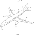
- Figure 6 illustrates an aircraft 500 which is one potential application for a component manufactured based upon the results of the method according to the embodiment illustrated in Figure 1 .
- the aircraft 500 illustrated in Figure 6 is a fixed wing aircraft 500 having a port wing 502 and starboard wing 503 carrying wing mounted engines 504a, 504b respectively.
- the wing mounted engines 504a, 504b are attached to the respective port and starboard wings via pylons (not shown).
- Each wing 502, 503 of the aircraft 500 has a cantilevered structure with a length extending in a span-wise direction from a root to a tip, the root being joined to an aircraft fuselage 506.
- the fuselage 506 and wings 502, 503 may take a variety of different planform shapes and profiles depending on the particular application.
- the fuselage 506 has a nose 507 and a tail 508, which forms the empennage of the aircraft 500, where respective horizontal and vertical stabilisers of the aircraft 500 are located.
- components for use in other applications may also be obtained via a transformation process based on the afore-described method.
- the method according to the first embodiment of the present invention provides a means for predicting the mechanical properties of a material subjected to a microstructural transformation, wherein the starting material stock (which is to undergo the simulated heat treatment process) is provided in the form of a billet, a bloom or an ingot.
- the method for predicting the mechanical properties of a material subjected to a microstructural transformation can also be used for processes wherein the starting material stock is provided in the form of an additively manufactured component.
- FIG. 7 depicts a method of predicting the mechanical properties of a material manufactured via an Electron Beam Melting additive manufacturing process.
- additive manufacturing processes such as Wire Feed Melting and Selective Laser Sintering, may be simulated during this step.
- the method according to the embodiment illustrated in Figure 7 includes a further solidification modelling step 603, prior to the heat treatment simulation step 604, wherein the solidification of the material subjected to the additive manufacturing process from a liquid phase material to a solid phase materials is simulated.
- the simulation performed as part of the solidification modelling step 603 is typically performed using the microstructural model generated during the modelling step 602.
- the microstructural model is a multi-phase field model, however it shall be appreciated that in other embodiments, other model types may be used.
- the model is able to better account for any microstructural changes which occur as a consequence of the additive manufacturing process.
- this helps the model to more accurately predict the mechanical properties of the material.
Landscapes
- Chemical & Material Sciences (AREA)
- Engineering & Computer Science (AREA)
- Materials Engineering (AREA)
- Physics & Mathematics (AREA)
- Life Sciences & Earth Sciences (AREA)
- Health & Medical Sciences (AREA)
- Manufacturing & Machinery (AREA)
- General Physics & Mathematics (AREA)
- Organic Chemistry (AREA)
- Mechanical Engineering (AREA)
- Metallurgy (AREA)
- Analytical Chemistry (AREA)
- Pathology (AREA)
- Immunology (AREA)
- Crystallography & Structural Chemistry (AREA)
- General Health & Medical Sciences (AREA)
- Biochemistry (AREA)
- Theoretical Computer Science (AREA)
- Food Science & Technology (AREA)
- Medicinal Chemistry (AREA)
- Computer Hardware Design (AREA)
- Evolutionary Computation (AREA)
- Geometry (AREA)
- General Engineering & Computer Science (AREA)
- Analysing Materials By The Use Of Radiation (AREA)
- Management, Administration, Business Operations System, And Electronic Commerce (AREA)
Applications Claiming Priority (1)
| Application Number | Priority Date | Filing Date | Title |
|---|---|---|---|
| IN202011052043 | 2020-11-30 |
Publications (1)
| Publication Number | Publication Date |
|---|---|
| EP4016366A1 true EP4016366A1 (de) | 2022-06-22 |
Family
ID=78528648
Family Applications (1)
| Application Number | Title | Priority Date | Filing Date |
|---|---|---|---|
| EP21203646.1A Pending EP4016366A1 (de) | 2020-11-30 | 2021-10-20 | Verfahren zur kombinierten modellierung mittels multi phase-field und crystal plasticity modellen |
Country Status (2)
| Country | Link |
|---|---|
| US (1) | US12625126B2 (de) |
| EP (1) | EP4016366A1 (de) |
Families Citing this family (2)
| Publication number | Priority date | Publication date | Assignee | Title |
|---|---|---|---|---|
| US12524924B2 (en) | 2023-06-30 | 2026-01-13 | Rtx Corporation | Generation of microstructural images of titanium alloys as a function of heat treatment conditions using conditional generative adversarial networks |
| CN117993202A (zh) * | 2024-02-08 | 2024-05-07 | 北京科技大学 | 一种基于扩散模型的材料显微组织演变模拟方法 |
Family Cites Families (1)
| Publication number | Priority date | Publication date | Assignee | Title |
|---|---|---|---|---|
| US6731996B1 (en) * | 1998-11-18 | 2004-05-04 | Alcan International Limited | Method of using isotropic plasticity to model the forming of anisotropic sheet |
-
2021
- 2021-10-20 EP EP21203646.1A patent/EP4016366A1/de active Pending
- 2021-10-27 US US17/512,453 patent/US12625126B2/en active Active
Non-Patent Citations (5)
| Title |
|---|
| CHOI ET AL: "Primary recrystallization modelling for interstitial free steels", MATERIALS SCIENCE, ELSEVIER, AMSTERDAM, NL, vol. 405, no. 1-2, 25 September 2005 (2005-09-25), pages 86 - 101, XP005015012, ISSN: 0921-5093, DOI: 10.1016/J.MSEA.2005.05.093 * |
| DADHICH RITESH ET AL: "Coupled Crystal Plasticity-Phase Field Modeling of Multi-Phase Metals", PROCEDIA STRUCTURAL INTEGRITY, vol. 14, 1 January 2019 (2019-01-01), pages 104 - 111, XP055915979, ISSN: 2452-3216, DOI: 10.1016/j.prostr.2019.05.014 * |
| HOJUN LIM ET AL: "Incorporating physically-based microstructures in materials modeling: Bridging phase field and crystal plasticity frameworks", MODELLING AND SIMULATION IN MATERIALS SCIENCE AND ENGINEERING, IOP PUBLISHING, BRISTOL, GB, vol. 24, no. 4, 25 April 2016 (2016-04-25), pages 45016, XP020302154, ISSN: 0965-0393, [retrieved on 20160425], DOI: 10.1088/0965-0393/24/4/045016 * |
| LIM H. ET AL: "Grain-scale experimental validation of crystal plasticity finite element simulations of tantalum oligocrystals", INTERNATIONAL JOURNAL OF PLASTICITY, vol. 60, 1 September 2014 (2014-09-01), AMSTERDAM, NL, pages 1 - 18, XP055915978, ISSN: 0749-6419, DOI: 10.1016/j.ijplas.2014.05.004 * |
| LUAN QINMENG ET AL: "Combining microstructural characterization with crystal plasticity and phase-field modelling for the study of static recrystallization in pure aluminium", COMPUTATIONAL MATERIALS SCIENCE, ELSEVIER, AMSTERDAM, NL, vol. 173, 25 November 2019 (2019-11-25), XP086019641, ISSN: 0927-0256, [retrieved on 20191125], DOI: 10.1016/J.COMMATSCI.2019.109419 * |
Also Published As
| Publication number | Publication date |
|---|---|
| US20220170901A1 (en) | 2022-06-02 |
| US12625126B2 (en) | 2026-05-12 |
Similar Documents
| Publication | Publication Date | Title |
|---|---|---|
| Wen et al. | A new dynamic recrystallization kinetics model for a Nb containing Ni-Fe-Cr-base superalloy considering influences of initial δ phase | |
| Huang et al. | A physical-based constitutive model to describe the strain-hardening and dynamic recovery behaviors of 5754 aluminum alloy | |
| Raghunathan et al. | Micromechanics of Ti–10V–2Fe–3Al: In situ synchrotron characterisation and modelling | |
| Velay et al. | Behavior modeling and microstructural evolutions of Ti–6Al–4V alloy under hot forming conditions | |
| Westermann et al. | Effects of particles and solutes on strength, work-hardening and ductile fracture of aluminium alloys | |
| Liu et al. | A three-dimensional multi-scale polycrystalline plasticity model coupled with damage for pure Ti with harmonic structure design | |
| Reddy et al. | Effect of temperature on the selection of deformation modes in Zircaloy-4 | |
| Wu et al. | The effects of grain morphology and crystallographic orientation on fatigue crack initiation in a metastable β titanium alloy Ti-7333 | |
| Reyes et al. | Grain size modeling of a Ni-base superalloy using cellular automata algorithm | |
| US12625126B2 (en) | Method of modelling of a material | |
| Agnoli et al. | Understanding and modeling of gain boundary pinning in Inconel718 | |
| Zhou et al. | Experimental study and crystal plasticity finite element simulations of nano-indentation-induced lattice rotation and the underlying mechanism in TC6 single α-grain | |
| Ribeiro et al. | Creep age forming: a short review of fundaments and applications | |
| Dunne | Inhomogeneity of microstructure in superplasticity and its effect on ductility | |
| Rae et al. | Effect of stress relaxation on the evolution of residual stress during heat treatment of Ti-6Al-4V | |
| Anderson et al. | Application of a multi-component mean field model to the coarsening behaviour of a nickel-based superalloy | |
| Simar et al. | Micro-mechanical modelling of ductile failure in 6005A aluminium using a physics based strain hardening law including stage IV | |
| Hoar et al. | Statistical modeling of microstructure evolution in a Ti-6Al-4V alloy during isothermal compression | |
| Singh et al. | Deformation twinning in zirconium: direct experimental observations and polycrystal plasticity predictions | |
| Zeng et al. | Effect of temperature, strain and microstructure on texture evolution of ti-6al-4v during hot rolling | |
| Ding et al. | High-temperature creep behavior of MoRe alloys: A mechanism-based polycrystal model verified by experiments | |
| Wijeyeratne et al. | A crystal visco-plastic model for Ni-base superalloys under low cycle fatigue | |
| Halder et al. | Polycrystal plasticity modeling of the anisotropy of Ti-6Al-4V under static & dynamic loadings | |
| Gariglio et al. | Dislocation density evolution in hot‑compressed dual‑phase titanium alloys: A phase‑resolved EBSD–Taylor framework | |
| Topilla et al. | Stress-strain distribution and failure mechanisms in dual-phase steels investigated with microstructure-based modeling |
Legal Events
| Date | Code | Title | Description |
|---|---|---|---|
| PUAI | Public reference made under article 153(3) epc to a published international application that has entered the european phase |
Free format text: ORIGINAL CODE: 0009012 |
|
| STAA | Information on the status of an ep patent application or granted ep patent |
Free format text: STATUS: THE APPLICATION HAS BEEN PUBLISHED |
|
| AK | Designated contracting states |
Kind code of ref document: A1 Designated state(s): AL AT BE BG CH CY CZ DE DK EE ES FI FR GB GR HR HU IE IS IT LI LT LU LV MC MK MT NL NO PL PT RO RS SE SI SK SM TR |
|
| STAA | Information on the status of an ep patent application or granted ep patent |
Free format text: STATUS: REQUEST FOR EXAMINATION WAS MADE |
|
| 17P | Request for examination filed |
Effective date: 20220902 |
|
| RBV | Designated contracting states (corrected) |
Designated state(s): AL AT BE BG CH CY CZ DE DK EE ES FI FR GB GR HR HU IE IS IT LI LT LU LV MC MK MT NL NO PL PT RO RS SE SI SK SM TR |
|
| STAA | Information on the status of an ep patent application or granted ep patent |
Free format text: STATUS: EXAMINATION IS IN PROGRESS |
|
| 17Q | First examination report despatched |
Effective date: 20251029 |