EP4016124B1 - Flugzeitberechnung mit inter-bin-delta-schätzung - Google Patents
Flugzeitberechnung mit inter-bin-delta-schätzung Download PDFInfo
- Publication number
- EP4016124B1 EP4016124B1 EP20214530.6A EP20214530A EP4016124B1 EP 4016124 B1 EP4016124 B1 EP 4016124B1 EP 20214530 A EP20214530 A EP 20214530A EP 4016124 B1 EP4016124 B1 EP 4016124B1
- Authority
- EP
- European Patent Office
- Prior art keywords
- time
- histogram
- photon
- time portion
- bin
- Prior art date
- Legal status (The legal status is an assumption and is not a legal conclusion. Google has not performed a legal analysis and makes no representation as to the accuracy of the status listed.)
- Active
Links
Images


Classifications
-
- G—PHYSICS
- G01—MEASURING; TESTING
- G01S—RADIO DIRECTION-FINDING; RADIO NAVIGATION; DETERMINING DISTANCE OR VELOCITY BY USE OF RADIO WAVES; LOCATING OR PRESENCE-DETECTING BY USE OF THE REFLECTION OR RERADIATION OF RADIO WAVES; ANALOGOUS ARRANGEMENTS USING OTHER WAVES
- G01S7/00—Details of systems according to groups G01S13/00, G01S15/00, G01S17/00
- G01S7/48—Details of systems according to groups G01S13/00, G01S15/00, G01S17/00 of systems according to group G01S17/00
- G01S7/483—Details of pulse systems
- G01S7/486—Receivers
- G01S7/4865—Time delay measurement, e.g. time-of-flight measurement, time of arrival measurement or determining the exact position of a peak
-
- G—PHYSICS
- G01—MEASURING; TESTING
- G01S—RADIO DIRECTION-FINDING; RADIO NAVIGATION; DETERMINING DISTANCE OR VELOCITY BY USE OF RADIO WAVES; LOCATING OR PRESENCE-DETECTING BY USE OF THE REFLECTION OR RERADIATION OF RADIO WAVES; ANALOGOUS ARRANGEMENTS USING OTHER WAVES
- G01S17/00—Systems using the reflection or reradiation of electromagnetic waves other than radio waves, e.g. lidar systems
- G01S17/02—Systems using the reflection of electromagnetic waves other than radio waves
- G01S17/06—Systems determining position data of a target
- G01S17/08—Systems determining position data of a target for measuring distance only
- G01S17/10—Systems determining position data of a target for measuring distance only using transmission of interrupted, pulse-modulated waves
-
- G—PHYSICS
- G01—MEASURING; TESTING
- G01S—RADIO DIRECTION-FINDING; RADIO NAVIGATION; DETERMINING DISTANCE OR VELOCITY BY USE OF RADIO WAVES; LOCATING OR PRESENCE-DETECTING BY USE OF THE REFLECTION OR RERADIATION OF RADIO WAVES; ANALOGOUS ARRANGEMENTS USING OTHER WAVES
- G01S17/00—Systems using the reflection or reradiation of electromagnetic waves other than radio waves, e.g. lidar systems
- G01S17/88—Lidar systems specially adapted for specific applications
- G01S17/89—Lidar systems specially adapted for specific applications for mapping or imaging
- G01S17/894—3D imaging with simultaneous measurement of time-of-flight at a 2D array of receiver pixels, e.g. time-of-flight cameras or flash lidar
-
- G—PHYSICS
- G01—MEASURING; TESTING
- G01S—RADIO DIRECTION-FINDING; RADIO NAVIGATION; DETERMINING DISTANCE OR VELOCITY BY USE OF RADIO WAVES; LOCATING OR PRESENCE-DETECTING BY USE OF THE REFLECTION OR RERADIATION OF RADIO WAVES; ANALOGOUS ARRANGEMENTS USING OTHER WAVES
- G01S7/00—Details of systems according to groups G01S13/00, G01S15/00, G01S17/00
- G01S7/48—Details of systems according to groups G01S13/00, G01S15/00, G01S17/00 of systems according to group G01S17/00
- G01S7/4808—Evaluating distance, position or velocity data
-
- G—PHYSICS
- G01—MEASURING; TESTING
- G01S—RADIO DIRECTION-FINDING; RADIO NAVIGATION; DETERMINING DISTANCE OR VELOCITY BY USE OF RADIO WAVES; LOCATING OR PRESENCE-DETECTING BY USE OF THE REFLECTION OR RERADIATION OF RADIO WAVES; ANALOGOUS ARRANGEMENTS USING OTHER WAVES
- G01S7/00—Details of systems according to groups G01S13/00, G01S15/00, G01S17/00
- G01S7/48—Details of systems according to groups G01S13/00, G01S15/00, G01S17/00 of systems according to group G01S17/00
- G01S7/483—Details of pulse systems
- G01S7/486—Receivers
- G01S7/4861—Circuits for detection, sampling, integration or read-out
- G01S7/4863—Detector arrays, e.g. charge-transfer gates
-
- G—PHYSICS
- G01—MEASURING; TESTING
- G01S—RADIO DIRECTION-FINDING; RADIO NAVIGATION; DETERMINING DISTANCE OR VELOCITY BY USE OF RADIO WAVES; LOCATING OR PRESENCE-DETECTING BY USE OF THE REFLECTION OR RERADIATION OF RADIO WAVES; ANALOGOUS ARRANGEMENTS USING OTHER WAVES
- G01S7/00—Details of systems according to groups G01S13/00, G01S15/00, G01S17/00
- G01S7/48—Details of systems according to groups G01S13/00, G01S15/00, G01S17/00 of systems according to group G01S17/00
- G01S7/483—Details of pulse systems
- G01S7/486—Receivers
- G01S7/487—Extracting wanted echo signals, e.g. pulse detection
- G01S7/4876—Extracting wanted echo signals, e.g. pulse detection by removing unwanted signals
-
- G—PHYSICS
- G01—MEASURING; TESTING
- G01S—RADIO DIRECTION-FINDING; RADIO NAVIGATION; DETERMINING DISTANCE OR VELOCITY BY USE OF RADIO WAVES; LOCATING OR PRESENCE-DETECTING BY USE OF THE REFLECTION OR RERADIATION OF RADIO WAVES; ANALOGOUS ARRANGEMENTS USING OTHER WAVES
- G01S17/00—Systems using the reflection or reradiation of electromagnetic waves other than radio waves, e.g. lidar systems
- G01S17/88—Lidar systems specially adapted for specific applications
- G01S17/93—Lidar systems specially adapted for specific applications for anti-collision purposes
- G01S17/931—Lidar systems specially adapted for specific applications for anti-collision purposes of land vehicles
Definitions
- the disclosure relates to time of flight calculations for a lidar transceiver.
- Lidar light detection and ranging
- CMOS SPAD Complementary Metal-oxide-semiconductor
- SPADs have a proven record of time-of-flight in time-correlated single photon counting (TCSPC) configuration for short range and low noise applications, such as fluorescence lifetime microscopy.
- TCSPC time-correlated single photon counting
- SPAD pixels are connected to time-to-digital converters (TDC) for time-of-flight estimation.
- TDC time-to-digital converters Due to internal and external noise, as well as the probabilistic nature of single-photon operation mode, one acquisition cycle typically comprises multiple time-of-flight measurements and a true signal is identified statistically.
- Adapting the use of SPADs to accommodate long range noise in automotive lidar applications requires a substantial redefinition of the architecture.
- a typical processing flow for lidar applications involves constructing a timestamp histogram and identifying a target reflection by identifying a peak in the histogram.
- US 2017/052065 A1 discloses a SPAD array with a gated histogram construction, in which a gating generator is controlled during a first sequence of acquisition periods so as to sweep a gating interval over the acquisition periods and identify a respective detection window for a sensing element, and during a second sequence of the acquisition periods to fix the gating interval for each sensing element to coincide with the respective detection window.
- a method of calculating time of flight of a lidar signal comprising:
- cumulative delta or phase allows the implementation of wider histogram bins without this meaning a significant loss in the accuracy of the measurements, thereby allowing a substantial reduction of memory requirements without a corresponding sacrifice of sensitivity and range resolution.
- the method also allows for the point of maximum photon events concentration within one or more histogram bins to be determined, disregarding the bin width, making it possible to estimate the range to a target with a higher precision.
- Intra-bin cumulative delta or phase value can be shared between group of bins or the compete histogram for further memory reduction.
- Other data such as second central moment of timestamps, may provide more useful information, such as material or relative orientation, without implying additional post-processing on the full histogram.
- a second central moment of an identified peak may be obtained from a sum of squares of the calculated time differences, for example by calculating a root mean square value from the cumulative total of time differences.
- the cumulative total of the calculated time difference may be combined for multiple time portions over the acquisition time period, which reduces the memory requirement further. Combining the cumulative total over multiple bins does not result in a loss of accuracy because noise will on average cancel out for bins having no peak over a background noise level.
- a measure of noise may be subtracted from the cumulative count of photons received during the time portion containing the identified peak.
- the reference point of each successive time portion may be at a mid-point of the time portion.
- t r a time from the start of the acquisition time period to the reference point of the time portion
- ⁇ ⁇ is the cumulative total of the calculated time difference
- H i is the cumulative count of photons
- H Noise is a measure of noise in the histogram.
- the measure of noise, H Noise may be calculated from an average of photon counts across the histogram other than the time portion containing the peak.
- a lidar transceiver comprising:
- the cumulative total of the calculated time difference may be combined for multiple time portions over the acquisition time period.
- the receiver may be a single photon avalanche diode.
- the receiver may comprise an array of single photon avalanche diodes, the processor being configured to perform steps i) to v) for each single photon avalanche diode in the array in parallel.
- Disclosed herein in general terms is a method and apparatus that separates peak detection and range estimation into two parallel processes.
- Wide-bin histogram bins can be used for target detection, thereby reducing memory requirements.
- Additional inter-bin cumulative delta or phase values per bin, group of bins or the complete histogram are estimated in real time for more accurate range estimation, thus achieving resolution and / or accuracy higher than would otherwise be imposed by the bin width of a histogram.
- the inter-bin cumulative delta or phase may be a real-time sum of timestamps relative to a reference point of each histogram bin, for example the bin middle, or in other words the phase relative to the reference.
- the technique leverages the fact that the total contribution from external noise (such as sunlight) and internal noise (the so called dark count rate) to inter-bin cumulative delta or phase value will tend to cancel out because the noise within a single laser shot is largely uniform. Changing noise between laser shots, or slowly shifting noise, will not result in clutter-edges (abrupt noise changes) observable in the histogram.
- external noise such as sunlight
- internal noise the so called dark count rate
- the characteristics of a true signal can be extracted by analysing a cumulative inter-bin delta or phase value, the bin count of corresponding bin, together with a measured noise level. For example, a peak location of a reflected signal can be estimated by dividing the final cumulative delta value by the bin count excluding noise counts, which can be approximated using available noise statistics, e.g. bin counts for other non-target bins. In a similar manner, more data, such as second central moment of timestamp, can be gathered, and may provide more information about the signal, e.g. material or relative orientation.
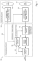
- FIG. 1 illustrates an example of a lidar transceiver 100 similar to that disclosed in EP3690475A1 .
- the lidar transceiver 100 includes sensor circuitry 104 and processing circuitry 102.
- the sensor circuitry 104 produces and senses detected signals corresponding to physical objects located in an operational region relative to a location of the sensor circuitry 104.
- the sensor circuitry 104 may include a SPAD array that senses optical signals and, in response, produces detected signals.
- the sensor circuitry 104 transmits a signal in the form of a light pulse that may be reflected from physical objects within the operational region of the transmitted signals using transmitter circuitry 114. Signals reflected from the target objects are detected via receiver circuitry 116 of the sensor circuitry 104. The produced signals and received reflected signals are used to determine a time-of-flight of the signal as transmitted and reflected.
- SPADs including Geiger-mode avalanche photodiodes
- SPADs are detectors capable of capturing individual photons with very high time-of-arrival resolution, typically of the order of a few tens of picoseconds.
- SPADs can be fabricated in dedicated semiconductor processes or in standard CMOS technologies, using known arrays of SPAD sensors, such as used in three-dimensional (3D) imaging cameras.
- the sensor circuitry 104 includes TX front-end circuitry 114 and RX front-end circuitry 116.
- the TX front-end circuitry 114 and RX front-end circuitry 116 are used to send reference signals and detect reflected signals, for example via a TX lens 115 and a RX lens 117 respectively.
- the reflected signals correspond to physical objects and are used to estimate a time-of-flight for the reference signal and reflected signals that is indicative of a distance of the physical object from the sensor circuitry 104.
- the apparatus 100 includes processing circuitry 102 in communication with the sensor circuitry 104.
- the processing circuitry 102 is used to generate a histogram using the detected signals and uses the histogram to determine or estimate distances of physical objects from the sensor circuitry 104.
- the processing circuitry 102 can include an array of processing circuits coupled to the SPAD array circuitry.
- the processing circuitry 102 and sensor circuitry 104 may be part of an automotive lidar system.
- the processing circuitry 102 includes a controller circuit 106, histogram circuit 112, digital signal processor 110, and storage circuit (e.g., random access memory, RAM) 108.
- the controller circuit 106 sends reference or timing signals to the TX and RX front-end circuitries 114, 116 to synchronize time origins for time-of-flight estimation.
- the controller circuit 106 can also control histogram parameters and/or settings, e.g., bin width settings.
- the TX and RX front-end circuitries 114, 116 can include a variety of known front-end signal-receiving circuitry and related logic for processing of I/O signals related to the controller circuit 106.
- the output of RX front-end circuitry 116 is a time-of-flight record of a single detection in digital format (hereinafter time or data record). Upon detection of the signal, the histogram is updated with the new data record.
- the histogram circuit 112 can be used to generate and store the histogram.
- the sensor circuitry 104 and the processing circuitry 102 can operate concurrently in real-time.
- the sensor circuitry 104 produces the detected signals while the processing circuitry 102 is constructing information for the histogram.
- the sensor circuitry 104 may operate in an autonomous, or semi-autonomous, driving mode.
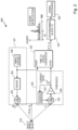
- Figure 2 illustrates an example of operation of the type of apparatus shown in Figure 1 .
- the physical objects e.g. object 219
- the range or distance r is calculated based on the time-of-flight t 1 -t 0 , where t 0 is the time at which the light signal is emitted from the emitter 220 and t 1 is the time at which the light signal is detected at the detector 222.
- Time stamping of a received signal can be made via an edge or peak using thresholding and time-to-digital converter (TDC) 232 or by use of an analog-to-digital converter (ADC) and processing (e.g., with the TDC and ADC being high speed circuits).
- the transmitter in Figure 2 is an optical-signal generation circuitry 221 and the receiver is an optical-signal processing circuitry 225, together forming the sensor circuitry 104 illustrated in Figure 1 .
- the optical-signal generation circuitry 221 generates optical radiation, which when reflected off physical objects such as object 219. Reflections are detected by the optical-signal processing circuitry 225.
- Additional circuitry is configured to process signals output from the optical-signal generation circuitry 221 and the optical-signal processing circuitry 225.
- the optical-signal generation circuitry 221 includes a transmitter driver 224, a timing engine 230, and a transmitter 220 that form a transmitter path (also referred to as a transmit path). Emission of optical radiation by the transmitter 220 is controlled by the transmitter driver 224 and timing engine 230 (which may form part of the controller circuit 106 in the processing circuitry 102 of Figure 1 ).
- the transmitter 220 constitutes an illuminator such as a laser.
- Example illuminators include a light emitting diode, an edge-emitting laser, a vertical cavity surface emitting laser, and a known array thereof.
- Optical radiation emitted by the transmitter 220 travels until it is reflected by physical objects (e.g., trees, buildings, other automotive vehicles). The reflected optical radiation is sensed/received by the detector 222 of the optical-signal processing circuitry 225, at which point time-of-flight of the emitted optical radiation is determined.
- the optical-signal processing circuitry 225 includes an array of single-photon avalanche diodes (SPADs) 222 and a corresponding array of threshold (level-detection) circuits 228 (as well as a quenching circuit 227 for each SPAD and threshold circuit 228).
- Each SPAD 222 is configured to detect the reflected optical radiation. Once detected by a SPAD 222, the optical radiation is thresholded (e.g., compared to a quiescent point by threshold circuit 228) before it is passed to additional circuitry for further processing.
- the sensor circuitry of the lidar system can further include a lens and a bandpass filter, which can be located in the lidar system with respect to the array of SPADs 222.
- the transmitter path may include a micro-electro-mechanical system (MEMS) scanner and a MEMS driver for two-dimensional (2D) steering of a laser beam or one-dimensional (1D) steering of an array of laser beams or line-laser.
- MEMS micro-electro-mechanical system
- the transmitter or transmitter path may include an optical phase array and drivers for scanning a laser beam.
- the transmitter or the transmitter path may include a VCSEL (vertical cavity surface emitting laser) array.
- VCSEL vertical cavity surface emitting laser
- the transmitter or transmitter path may include a lens system for spreading the beam into a complete field-of-view (e.g. flash) or for laser beam collimation. It can be thus be appreciated that a number of different configurations can be implemented for the transmitter or transmitter path.
- a lens system for spreading the beam into a complete field-of-view (e.g. flash) or for laser beam collimation.
- the additional circuitry which is configured to process the at least one signal output form the optical-signal generation circuitry 221 and the optical-signal processing circuitry 225, comprises a time-to-digital converter (TDC) 232, a histogram circuitry (e.g., block/IC) 234, and signal processing circuitry 236.
- the TDC 232 is configured to receive the detected reflected optical radiation from the optical-signal processing circuitry 225 (which is indicative of time of incidence of a single photon) as detected by the constituent SPAD array 222. Time of incidence is used to increment a count in memory of the respective incidence photon of the optical-signal processing circuitry 225 via the histogram circuitry 234 and for signal processing via the signal processing circuitry 236.
- the timing circuit Upon detection of a reflected signal, the timing circuit (e.g., the TDC 232 illustrated in the embodiment of Figure 2 ) outputs the time difference between the event and the reference/signal, referred to as measured time-of-flight record, that can be written in a time-of-flight record register or latch. The records from time-of-flight registers or latches can be read-out and passed to the histogram block for subsequent histogram generation and storage.
- the timing circuit e.g., the TDC 232
- the timing circuit 232 may form part of the optical-signal processing circuitry 225.
- the digital signal processor (e.g., signal processing circuitry 236) can be responsible for execution of algorithms for signal detection (e.g., CFAR or "Constant False Alarm Rate” detection algorithms) and for writing detected signals to RAM.
- signal detection e.g., CFAR or "Constant False Alarm Rate” detection algorithms
- a final point cloud generated from distinct reflections can be retrieved from RAM. Processing by the digital signal processor may extend beyond signal detection including but not limited to: subsequent point-cloud filtering, segmentation, object classification, and state estimation.
- a storage circuit such as the storage circuit 108 depicted in Figure 1 , can be configured to store respective counts of the photons that arrive in a plurality of different time bins. While obtaining the measurements, the memory that is associated with the optical-signal processing circuitry 225 stores respective counts of the photons that arrive at the processing circuitry in multiple different time bins, which span the detection window that the transmitter driver 224 and timing engine 230 set for the optical-signal processing circuitry 225.
- a controller can process a histogram of the respective counts over the different bins for the sensing circuitry so as to derive and output a respective time-of-arrival value for the optical-signal processing circuitry 225.
- embodiments are not to be limited to use of a TDC and can include apparatuses having an analog-to-digital converter (ADC).
- ADC analog-to-digital converter
- the detected reflected optical radiation is provided to the ADC via a correlated double sampling (CDS) circuit that receives the detected signal from the optical-signal processing circuitry 225 and outputs a sampled signal whose voltage is proportional to the detected time-of-arrival of the photon to the ADC.
- CDS correlated double sampling
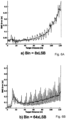
- Figures 3A-3C illustrate examples of histograms with different bin widths, each histogram having bins of equal width over the operational region corresponding to an acquisition time period.
- a TDC resolution of 333ps may be assumed in these examples (e.g., LSB in each case corresponding to 333ps).
- a histogram with bin width of 1xLSB e.g., bin width 1xLSB/0.33 ns and having 2048 bins
- a strong signal from a physical object at 17m results in a distinct peak 309, while a weaker signal from another physical object at 81m is indistinguishable, as indicated by 311.
- both peaks at 17m and at 81m are distinguishable, as illustrated respectively by 313 and 315.
- a possible disadvantage (depending on the application and specific embodiment) of 8xLSB bin width is the loss of the range resolution, being 40cm for 256 bins as against 5cm for 2048 bins.
- a 40cm range resolution, depending on the use-case, may be sufficient for the other physical objects at 81m (e.g., as illustrated by 315) but not for the physical object at 17m (e.g., as illustrated by 313).
- 3C in which bin width is set to 64xLSB (e.g., bin width 64xLSB/21.33 ns and having 32 bins), demonstrates a different side effect at the other extreme: if bin width is set too wide, a weak signal is washed out with noise, as illustrated by 319 (e.g., peak at 81 m) as compared to 317 (e.g., peak at 17 m).
- 64xLSB e.g., bin width 64xLSB/21.33 ns and having 32 bins
- FIGS 4A-4C The effect of range resolution due to the increase of the bin widths is shown in Figures 4A-4C , in which the RMS distance error is plotted as a function of target distance for different size bins, with Figure 4A showing results for bins of 1xLSB, Figure 4B bins of 8xLSB and Figure 4C bins of 64xLSB.
- the error (dotted line) is shown along with a moving mean value (solid line).
- the smallest errors are shown for the smallest bin size, as would be expected, together with the highest stability over the range detected.
- Wider bin widths of 8xLSB or 64xLSB suffer from higher errors as well as sampling errors, which can be seen in the saw-tooth shape of each plot.
- the accuracy also worsens as the signal becomes weaker with higher target distances, such as it is the case when a target recedes from a lidar based on a SPAD detector.
- One solution to the above problems is to implement adaptive histograms, in which the bin width is adapted as a function of target distance, as disclosed in EP3690475A1 .
- This can result in a reduced memory requirement by using wider bins for smaller target distances where the percentage accuracy is acceptable, while using narrower bins for higher target distances.
- a problem with this, however, is that the memory requirements are still substantial and the issue of using smaller bins for higher target distances where peaks may become indistinguishable, as shown in Figure 3A , remains.
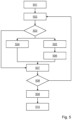
- Figure 5 illustrates an example method of calculating time of flight of a lidar signal, as carried out by a lidar transceiver having a transmitter, receiver and processor.
- a histogram is defined in terms of a number of bins, each having a defined width, the histogram covering an acquisition time period with a plurality of first bins for recording photon counts at each of a plurality of time portions over the acquisition time period and a corresponding plurality of second bins for recording a cumulative time difference between an arrival time of a photon and a reference point of the time portion.
- an acquisition time period is started and a light pulse is transmitted by the transmitter. The light pulse travels to any objects in a line of sight of the transmitter and photons are reflected back to the receiver.
- a count of light pulses is incremented and, if the count has not yet reached a predetermined number of light pulses (step 508), the process starting from step 502 repeats.
- the resulting histogram is analysed to determine a peak from the photon counts in the first bins.
- a time of flight is estimated based on the reference point of the time portion covered by the first bin and the cumulative time difference in the second bin.
- This method of calculating time of flight solves the above-mentioned problems by taking into account the distribution of photon events within a single bin or a number of bins by considering a timestamp relative to a reference point set.
- the range estimation achieved considers the effect of the sum of timestamps relative to the reference point to determine the point, within the bin, of the highest concentration of photon events. This in turn corresponds to the position of the target, given the fact that the total contribution from external (sunlight) and internal noise (so called dark count rate) to inter-bin cumulative delta or phase value will tend to cancel out, as the noise within a single laser shot is largely uniform.
- sampling errors are overcome because the range-detection is not based on merely histogram peak detection.
- sensitivity corresponds roughly to the sensitivity of a traditional histogram-based approach of the same bin-width, i.e. higher that of 1xLSB (as a higher portion of a weak signal is integrated into a single bin, as demonstrated in Figure 3B ).
- the timestamp relative to the reference point will vary. Selection of broader bin widths allows for the obtention of greater magnitudes for the timestamps relative to the reference point within a single bin.
- the memory requirement is thereby reduced by factor of 2.3 for a similar accuracy.
- the memory requirements may be further reduced by sharing intra-bin cumulative delta or phase-values between multiple pixels or a complete histogram. Also, the maximum count is capped by the number of measurement cycles and could be lower than 12bits.
- Equation 1 shows an example of how the inter-bin cumulative delta or phase value may be calculated.
- the result is then used in signal processing, together with the histogram analysis, to determine the range estimation of the target position.
- ⁇ refers to the different timestamp relative to the reference point
- H i corresponds to the photon detection count stored at the histogram bin under analysis
- H Noise represents the noise level from the surroundings of the histogram bin under analysis or the complete histogram.
- the approximation for the noise can be achieved, for example, by computing the mean or the median of the neighbouring histogram bins on both sides of the histogram bin of interest.
- ⁇ final ⁇ ⁇ H i ⁇ H noise ⁇
- the time of flight may be estimated from the cumulative total of the calculated time difference, ⁇ ⁇ for the time portion of the histogram containing the identified peak. This may be done by dividing the cumulative total of the calculated time difference by the cumulative count of photons, H i , received during the time portion. A measure of noise, H Noise , may be subtracted from the cumulative count of photons, H i . It is important to note that the formula presented in equation 1, is just one of the many principles approaches that could be considered when using inter-bin delta.
- gathering more data may provide more useful information about the signal, e.g. material or relative orientation, while keeping memory requirements lower than of a full histogram.
Landscapes
- Engineering & Computer Science (AREA)
- Physics & Mathematics (AREA)
- Computer Networks & Wireless Communication (AREA)
- General Physics & Mathematics (AREA)
- Radar, Positioning & Navigation (AREA)
- Remote Sensing (AREA)
- Electromagnetism (AREA)
- Optical Radar Systems And Details Thereof (AREA)
Claims (9)
- Verfahren zum Berechnen einer Laufzeit eines Lidar-Signals, wobei das Verfahren umfasst:i) Übertragen eines Lichtpulses, um einen Erfassungszeitraum zu starten (502), der eine Vielzahl von aufeinanderfolgenden Zeitabschnitten aufweist;ii) für jeden aufeinanderfolgenden Zeitabschnitt, wenn ein Photon empfangen wird (503):iia) Aufzeichnen (505) eines Zeitpunkts, an dem das Photon empfangen wurde;iib) Aktualisieren (504) eines Histogramms, um eine kumulative Zählung von Photonen aufzuzeichnen, die während des Zeitabschnitts empfangen wurden;iic) Berechnen (505) einer Zeitdifferenz zwischen dem Zeitpunkt, an dem das Photon empfangen wurde, und einem Referenzpunkt des Zeitabschnitts;iid) Aktualisieren (506) eines kumulativen Gesamtwerts der berechneten Zeitdifferenz für den Zeitabschnitt;iii) Wiederholen der Schritte i) bis iid) für eine Abfolge von N übertragenen Lichtpulsen;iv) Identifizieren (509) einer Spitze in einem Zeitabschnitt des Histogramms; undv) Schätzen (510) einer Laufzeit aus dem kumulativen Gesamtwert der berechneten Zeitdifferenz für den Zeitabschnitt des Histogramms, das die identifizierte Spitze enthält.
- Verfahren nach Anspruch 1, wobei der Schritt v) ein Teilen des kumulativen Gesamtwerts der berechneten Zeitdifferenz durch die kumulative Zählung von Photonen umfasst, die während des Zeitabschnitts empfangen wurden, der die identifizierte Spitze enthält.
- Verfahren nach Anspruch 2, wobei eine Messung eines Rauschens von der kumulativen Zählung von Photonen subtrahiert wird, die während des Zeitabschnitts empfangen wurden, der die identifizierte Spitze enthält.
- Verfahren nach einem der vorhergehenden Ansprüche, wobei der Referenzpunkt von jedem aufeinanderfolgenden Zeitabschnitt ein Mittelpunkt des Zeitabschnitts ist.
- Verfahren nach einem der vorhergehenden Ansprüche, wobei die Laufzeit, t, für die identifizierte Spitze berechnet wird aus:

HRauschen eine Messung eines Rauschens in dem Histogramm ist. - Verfahren nach Anspruch 5, wobei
HRauschen aus einem Durchschnitt von Photonenzählungen über dem Histogramm berechnet wird, das verschieden von dem Zeitabschnitt ist, der die Spitze enthält. - Lidar-Transceiver (100), umfassend:einen Sender (114), der konfiguriert ist zum Senden von Lichtpulsen;einen Empfänger (116), der konfiguriert ist zum Empfangen von reflektierten Photonen aus den Lichtpulsen, die von dem Sender gesendet wurden; undeine Verarbeitungsschaltungsanordnung (102), die mit dem Sender und dem Empfänger verbunden ist, wobei die Verarbeitungsschaltungsanordnung konfiguriert ist zum:i) Starten eines Erfassungszeitraums, indem der Sender veranlasst wird, einen Lichtpuls zu senden;ii) für eine Vielzahl von aufeinanderfolgenden Zeitabschnitten in dem Erfassungszeitraum, wenn ein Photon empfangen wird:iia) Aufzeichnen eines Zeitpunkts, an dem das Photon empfangen wurde;iib) Aktualisieren eines Histogramms, um eine kumulative Zählung von Photonen aufzuzeichnen, die während des Zeitabschnitts in dem Empfänger empfangen wurden;iic) Berechnen einer Zeitdifferenz zwischen dem Zeitpunkt, an dem das Photon empfangen wurde, und einem Referenzpunkt des Zeitabschnitts;iid) Aktualisieren eines kumulativen Gesamtwerts der berechneten Zeitdifferenz für den Zeitabschnitt;iii) Wiederholen der Schritte i) bis iid) für eine Abfolge von N übertragenen Lichtpulsen;iv) Identifizieren einer Spitze in einem Zeitabschnitt des Histogramms; undv) Schätzen einer Laufzeit aus dem kumulativen Gesamtwert der berechneten Zeitdifferenz für den Zeitabschnitt des Histogramms, das die identifizierte Spitze enthält.
- Lidar-Transceiver (100) nach Anspruch 7, wobei der Empfänger (116) eine Einzelphoton-Avalanche-Diode, SPAD, umfasst.
- Lidar-Transceiver (100) nach Anspruch 7, wobei der Empfänger (116) ein Array von SPADs umfasst, wobei die Verarbeitungsschaltungsanordnung (102) konfiguriert ist zum parallelen Durchführen der Schritte i) bis) für jede SPAD in dem Array.
Priority Applications (3)
| Application Number | Priority Date | Filing Date | Title |
|---|---|---|---|
| EP20214530.6A EP4016124B1 (de) | 2020-12-16 | 2020-12-16 | Flugzeitberechnung mit inter-bin-delta-schätzung |
| US17/451,685 US12449515B2 (en) | 2020-12-16 | 2021-10-21 | Time of flight calculation with inter-bin delta estimation |
| CN202111525716.XA CN114636991A (zh) | 2020-12-16 | 2021-12-14 | 利用箱间增量估计的飞行时间计算 |
Applications Claiming Priority (1)
| Application Number | Priority Date | Filing Date | Title |
|---|---|---|---|
| EP20214530.6A EP4016124B1 (de) | 2020-12-16 | 2020-12-16 | Flugzeitberechnung mit inter-bin-delta-schätzung |
Publications (2)
| Publication Number | Publication Date |
|---|---|
| EP4016124A1 EP4016124A1 (de) | 2022-06-22 |
| EP4016124B1 true EP4016124B1 (de) | 2025-06-04 |
Family
ID=73854791
Family Applications (1)
| Application Number | Title | Priority Date | Filing Date |
|---|---|---|---|
| EP20214530.6A Active EP4016124B1 (de) | 2020-12-16 | 2020-12-16 | Flugzeitberechnung mit inter-bin-delta-schätzung |
Country Status (3)
| Country | Link |
|---|---|
| US (1) | US12449515B2 (de) |
| EP (1) | EP4016124B1 (de) |
| CN (1) | CN114636991A (de) |
Families Citing this family (5)
| Publication number | Priority date | Publication date | Assignee | Title |
|---|---|---|---|---|
| FR3117587B1 (fr) * | 2020-12-11 | 2022-12-23 | Commissariat Energie Atomique | Méthode de mesure compressive de la distribution statistique d’une grandeur physique |
| US11675077B2 (en) * | 2021-03-08 | 2023-06-13 | Lg Innotek Co., Ltd. | Systems and methods for analyzing waveforms using pulse shape information |
| WO2024019988A1 (en) | 2022-07-18 | 2024-01-25 | Cellsbin, Inc. | Devices for biological analysis |
| US11740337B1 (en) | 2022-08-15 | 2023-08-29 | Aurora Operations, Inc. | Light detection and ranging (lidar) sensor system including transceiver device |
| CN119667640B (zh) * | 2025-02-21 | 2025-05-27 | 山东省科学院海洋仪器仪表研究所 | 一种光子计数激光雷达信号处理方法及系统 |
Family Cites Families (5)
| Publication number | Priority date | Publication date | Assignee | Title |
|---|---|---|---|---|
| US9502458B2 (en) | 2015-03-10 | 2016-11-22 | Stmicroelectronics (Research & Development) Limited | Circuit for generating direct timing histogram data in response to photon detection |
| US10620300B2 (en) | 2015-08-20 | 2020-04-14 | Apple Inc. | SPAD array with gated histogram construction |
| US11656342B2 (en) | 2019-01-21 | 2023-05-23 | Nxp B.V. | Histogram-based signal detection with sub-regions corresponding to adaptive bin widths |
| US11428812B2 (en) * | 2019-03-07 | 2022-08-30 | Luminar, Llc | Lidar system with range-ambiguity mitigation |
| CN114616443A (zh) * | 2019-11-05 | 2022-06-10 | 索尼半导体解决方案公司 | 感测装置和测距设备 |
-
2020
- 2020-12-16 EP EP20214530.6A patent/EP4016124B1/de active Active
-
2021
- 2021-10-21 US US17/451,685 patent/US12449515B2/en active Active
- 2021-12-14 CN CN202111525716.XA patent/CN114636991A/zh active Pending
Also Published As
| Publication number | Publication date |
|---|---|
| EP4016124A1 (de) | 2022-06-22 |
| US20220187430A1 (en) | 2022-06-16 |
| CN114636991A (zh) | 2022-06-17 |
| US12449515B2 (en) | 2025-10-21 |
Similar Documents
| Publication | Publication Date | Title |
|---|---|---|
| EP4016124B1 (de) | Flugzeitberechnung mit inter-bin-delta-schätzung | |
| CN111538020B (zh) | 含对应于适应性柱条宽度的子区的基于直方图的信号检测 | |
| CN114424086B (zh) | 用于lidar测量的处理系统 | |
| US12481042B2 (en) | Time of flight sensor | |
| US12153133B2 (en) | Independent per-pixel integration registers for LIDAR measurements | |
| JP7620330B2 (ja) | 適応型多重パルスlidarシステム | |
| KR20220145845A (ko) | 솔리드 스테이트 LiDAR용 잡음 필터링 시스템 및 방법 | |
| EP3457177B1 (de) | Abstandsmessvorrichtung | |
| US20220035011A1 (en) | Temporal jitter in a lidar system | |
| CN112817001B (zh) | 一种飞行时间测距方法、系统和设备 | |
| CN110632577B (zh) | 时间编码解调处理电路及方法 | |
| US20180364337A1 (en) | LiDAR SYSTEM AND METHOD EMPLOYING LATE-LOCK GEIGER MODE DETECTION | |
| CN111538026B (zh) | 一种激光测距方法及系统 | |
| EP4372410A1 (de) | Lidar-entfernungsmessverfahren, lidar und computerlesbares speichermedium | |
| CN112470026A (zh) | 激光雷达及其探测方法、存储介质和探测系统 | |
| US11573302B2 (en) | LiDAR system comprising a Geiger-mode avalanche photodiode-based receiver having pixels with multiple-return capability | |
| US20230194666A1 (en) | Object Reflectivity Estimation in a LIDAR System | |
| US20230375678A1 (en) | Photoreceiver having thresholded detection | |
| US20250264586A1 (en) | Methods and devices for identifying peaks in histograms | |
| WO2022206031A1 (zh) | 确定噪声水平的方法、激光雷达以及测距方法 | |
| US12411244B2 (en) | Time of flight sensing | |
| KR102895523B1 (ko) | 적응형 다중 펄스 lidar 시스템 | |
| EP3963368B1 (de) | Zeitlicher jitter in einem lidar-system | |
| WO2025176071A1 (zh) | 测速方法、装置和激光雷达系统 | |
| CN120428195A (zh) | 信号处理的装置、方法和系统 |
Legal Events
| Date | Code | Title | Description |
|---|---|---|---|
| PUAI | Public reference made under article 153(3) epc to a published international application that has entered the european phase |
Free format text: ORIGINAL CODE: 0009012 |
|
| STAA | Information on the status of an ep patent application or granted ep patent |
Free format text: STATUS: THE APPLICATION HAS BEEN PUBLISHED |
|
| AK | Designated contracting states |
Kind code of ref document: A1 Designated state(s): AL AT BE BG CH CY CZ DE DK EE ES FI FR GB GR HR HU IE IS IT LI LT LU LV MC MK MT NL NO PL PT RO RS SE SI SK SM TR |
|
| STAA | Information on the status of an ep patent application or granted ep patent |
Free format text: STATUS: REQUEST FOR EXAMINATION WAS MADE |
|
| 17P | Request for examination filed |
Effective date: 20221222 |
|
| RBV | Designated contracting states (corrected) |
Designated state(s): AL AT BE BG CH CY CZ DE DK EE ES FI FR GB GR HR HU IE IS IT LI LT LU LV MC MK MT NL NO PL PT RO RS SE SI SK SM TR |
|
| GRAP | Despatch of communication of intention to grant a patent |
Free format text: ORIGINAL CODE: EPIDOSNIGR1 |
|
| STAA | Information on the status of an ep patent application or granted ep patent |
Free format text: STATUS: GRANT OF PATENT IS INTENDED |
|
| RIC1 | Information provided on ipc code assigned before grant |
Ipc: G01S 17/931 20200101ALN20250204BHEP Ipc: G01S 7/4863 20200101ALN20250204BHEP Ipc: G01S 17/10 20200101ALI20250204BHEP Ipc: G01S 7/487 20060101ALI20250204BHEP Ipc: G01S 7/4865 20200101AFI20250204BHEP |
|
| INTG | Intention to grant announced |
Effective date: 20250220 |
|
| GRAS | Grant fee paid |
Free format text: ORIGINAL CODE: EPIDOSNIGR3 |
|
| GRAA | (expected) grant |
Free format text: ORIGINAL CODE: 0009210 |
|
| STAA | Information on the status of an ep patent application or granted ep patent |
Free format text: STATUS: THE PATENT HAS BEEN GRANTED |
|
| AK | Designated contracting states |
Kind code of ref document: B1 Designated state(s): AL AT BE BG CH CY CZ DE DK EE ES FI FR GB GR HR HU IE IS IT LI LT LU LV MC MK MT NL NO PL PT RO RS SE SI SK SM TR |
|
| REG | Reference to a national code |
Ref country code: GB Ref legal event code: FG4D |
|
| REG | Reference to a national code |
Ref country code: CH Ref legal event code: EP |
|
| REG | Reference to a national code |
Ref country code: DE Ref legal event code: R096 Ref document number: 602020052233 Country of ref document: DE |
|
| REG | Reference to a national code |
Ref country code: IE Ref legal event code: FG4D |
|
| REG | Reference to a national code |
Ref country code: NL Ref legal event code: MP Effective date: 20250604 |
|
| PG25 | Lapsed in a contracting state [announced via postgrant information from national office to epo] |
Ref country code: FI Free format text: LAPSE BECAUSE OF FAILURE TO SUBMIT A TRANSLATION OF THE DESCRIPTION OR TO PAY THE FEE WITHIN THE PRESCRIBED TIME-LIMIT Effective date: 20250604 Ref country code: ES Free format text: LAPSE BECAUSE OF FAILURE TO SUBMIT A TRANSLATION OF THE DESCRIPTION OR TO PAY THE FEE WITHIN THE PRESCRIBED TIME-LIMIT Effective date: 20250604 |
|
| REG | Reference to a national code |
Ref country code: LT Ref legal event code: MG9D |
|
| PG25 | Lapsed in a contracting state [announced via postgrant information from national office to epo] |
Ref country code: NO Free format text: LAPSE BECAUSE OF FAILURE TO SUBMIT A TRANSLATION OF THE DESCRIPTION OR TO PAY THE FEE WITHIN THE PRESCRIBED TIME-LIMIT Effective date: 20250904 Ref country code: GR Free format text: LAPSE BECAUSE OF FAILURE TO SUBMIT A TRANSLATION OF THE DESCRIPTION OR TO PAY THE FEE WITHIN THE PRESCRIBED TIME-LIMIT Effective date: 20250905 |
|
| PG25 | Lapsed in a contracting state [announced via postgrant information from national office to epo] |
Ref country code: PL Free format text: LAPSE BECAUSE OF FAILURE TO SUBMIT A TRANSLATION OF THE DESCRIPTION OR TO PAY THE FEE WITHIN THE PRESCRIBED TIME-LIMIT Effective date: 20250604 |
|
| PG25 | Lapsed in a contracting state [announced via postgrant information from national office to epo] |
Ref country code: BG Free format text: LAPSE BECAUSE OF FAILURE TO SUBMIT A TRANSLATION OF THE DESCRIPTION OR TO PAY THE FEE WITHIN THE PRESCRIBED TIME-LIMIT Effective date: 20250604 |
|
| PG25 | Lapsed in a contracting state [announced via postgrant information from national office to epo] |
Ref country code: HR Free format text: LAPSE BECAUSE OF FAILURE TO SUBMIT A TRANSLATION OF THE DESCRIPTION OR TO PAY THE FEE WITHIN THE PRESCRIBED TIME-LIMIT Effective date: 20250604 |
|
| PG25 | Lapsed in a contracting state [announced via postgrant information from national office to epo] |
Ref country code: RS Free format text: LAPSE BECAUSE OF FAILURE TO SUBMIT A TRANSLATION OF THE DESCRIPTION OR TO PAY THE FEE WITHIN THE PRESCRIBED TIME-LIMIT Effective date: 20250904 |
|
| PG25 | Lapsed in a contracting state [announced via postgrant information from national office to epo] |
Ref country code: LV Free format text: LAPSE BECAUSE OF FAILURE TO SUBMIT A TRANSLATION OF THE DESCRIPTION OR TO PAY THE FEE WITHIN THE PRESCRIBED TIME-LIMIT Effective date: 20250604 |
|
| PG25 | Lapsed in a contracting state [announced via postgrant information from national office to epo] |
Ref country code: NL Free format text: LAPSE BECAUSE OF FAILURE TO SUBMIT A TRANSLATION OF THE DESCRIPTION OR TO PAY THE FEE WITHIN THE PRESCRIBED TIME-LIMIT Effective date: 20250604 |