EP4016097B1 - Vorrichtung zur simulation eines batteriepacks und verfahren zur prüfung der batterieverwaltungseinheit unter verwendung derselben - Google Patents
Vorrichtung zur simulation eines batteriepacks und verfahren zur prüfung der batterieverwaltungseinheit unter verwendung derselben Download PDFInfo
- Publication number
- EP4016097B1 EP4016097B1 EP21747249.7A EP21747249A EP4016097B1 EP 4016097 B1 EP4016097 B1 EP 4016097B1 EP 21747249 A EP21747249 A EP 21747249A EP 4016097 B1 EP4016097 B1 EP 4016097B1
- Authority
- EP
- European Patent Office
- Prior art keywords
- battery
- value
- battery pack
- management unit
- unit
- Prior art date
- Legal status (The legal status is an assumption and is not a legal conclusion. Google has not performed a legal analysis and makes no representation as to the accuracy of the status listed.)
- Active
Links
Images

Classifications
-
- G—PHYSICS
- G01—MEASURING; TESTING
- G01R—MEASURING ELECTRIC VARIABLES; MEASURING MAGNETIC VARIABLES
- G01R31/00—Arrangements for testing electric properties; Arrangements for locating electric faults; Arrangements for electrical testing characterised by what is being tested not provided for elsewhere
- G01R31/28—Testing of electronic circuits, e.g. by signal tracer
- G01R31/282—Testing of electronic circuits specially adapted for particular applications not provided for elsewhere
- G01R31/2827—Testing of electronic protection circuits
-
- G—PHYSICS
- G01—MEASURING; TESTING
- G01R—MEASURING ELECTRIC VARIABLES; MEASURING MAGNETIC VARIABLES
- G01R31/00—Arrangements for testing electric properties; Arrangements for locating electric faults; Arrangements for electrical testing characterised by what is being tested not provided for elsewhere
- G01R31/36—Arrangements for testing, measuring or monitoring the electrical condition of accumulators or electric batteries, e.g. capacity or state of charge [SoC]
- G01R31/382—Arrangements for monitoring battery or accumulator variables, e.g. SoC
- G01R31/3842—Arrangements for monitoring battery or accumulator variables, e.g. SoC combining voltage and current measurements
-
- G—PHYSICS
- G01—MEASURING; TESTING
- G01R—MEASURING ELECTRIC VARIABLES; MEASURING MAGNETIC VARIABLES
- G01R35/00—Testing or calibrating of apparatus covered by the other groups of this subclass
-
- G—PHYSICS
- G06—COMPUTING OR CALCULATING; COUNTING
- G06F—ELECTRIC DIGITAL DATA PROCESSING
- G06F30/00—Computer-aided design [CAD]
- G06F30/20—Design optimisation, verification or simulation
-
- H—ELECTRICITY
- H01—ELECTRIC ELEMENTS
- H01M—PROCESSES OR MEANS, e.g. BATTERIES, FOR THE DIRECT CONVERSION OF CHEMICAL ENERGY INTO ELECTRICAL ENERGY
- H01M10/00—Secondary cells; Manufacture thereof
- H01M10/42—Methods or arrangements for servicing or maintenance of secondary cells or secondary half-cells
- H01M10/425—Structural combination with electronic components, e.g. electronic circuits integrated to the outside of the casing
-
- H—ELECTRICITY
- H01—ELECTRIC ELEMENTS
- H01M—PROCESSES OR MEANS, e.g. BATTERIES, FOR THE DIRECT CONVERSION OF CHEMICAL ENERGY INTO ELECTRICAL ENERGY
- H01M10/00—Secondary cells; Manufacture thereof
- H01M10/42—Methods or arrangements for servicing or maintenance of secondary cells or secondary half-cells
- H01M10/4285—Testing apparatus
-
- H—ELECTRICITY
- H01—ELECTRIC ELEMENTS
- H01M—PROCESSES OR MEANS, e.g. BATTERIES, FOR THE DIRECT CONVERSION OF CHEMICAL ENERGY INTO ELECTRICAL ENERGY
- H01M10/00—Secondary cells; Manufacture thereof
- H01M10/42—Methods or arrangements for servicing or maintenance of secondary cells or secondary half-cells
- H01M10/48—Accumulators combined with arrangements for measuring, testing or indicating the condition of cells, e.g. the level or density of the electrolyte
-
- G—PHYSICS
- G01—MEASURING; TESTING
- G01R—MEASURING ELECTRIC VARIABLES; MEASURING MAGNETIC VARIABLES
- G01R31/00—Arrangements for testing electric properties; Arrangements for locating electric faults; Arrangements for electrical testing characterised by what is being tested not provided for elsewhere
- G01R31/36—Arrangements for testing, measuring or monitoring the electrical condition of accumulators or electric batteries, e.g. capacity or state of charge [SoC]
- G01R31/389—Measuring internal impedance, internal conductance or related variables
-
- H—ELECTRICITY
- H01—ELECTRIC ELEMENTS
- H01M—PROCESSES OR MEANS, e.g. BATTERIES, FOR THE DIRECT CONVERSION OF CHEMICAL ENERGY INTO ELECTRICAL ENERGY
- H01M10/00—Secondary cells; Manufacture thereof
- H01M10/42—Methods or arrangements for servicing or maintenance of secondary cells or secondary half-cells
- H01M10/425—Structural combination with electronic components, e.g. electronic circuits integrated to the outside of the casing
- H01M2010/4271—Battery management systems including electronic circuits, e.g. control of current or voltage to keep battery in healthy state, cell balancing
-
- H—ELECTRICITY
- H01—ELECTRIC ELEMENTS
- H01M—PROCESSES OR MEANS, e.g. BATTERIES, FOR THE DIRECT CONVERSION OF CHEMICAL ENERGY INTO ELECTRICAL ENERGY
- H01M2200/00—Safety devices for primary or secondary batteries
-
- H—ELECTRICITY
- H02—GENERATION; CONVERSION OR DISTRIBUTION OF ELECTRIC POWER
- H02H—EMERGENCY PROTECTIVE CIRCUIT ARRANGEMENTS
- H02H7/00—Emergency protective circuit arrangements specially adapted for specific types of electric machines or apparatus or for sectionalised protection of cable or line systems, and effecting automatic switching in the event of an undesired change from normal working conditions
- H02H7/18—Emergency protective circuit arrangements specially adapted for specific types of electric machines or apparatus or for sectionalised protection of cable or line systems, and effecting automatic switching in the event of an undesired change from normal working conditions for batteries; for accumulators
-
- Y—GENERAL TAGGING OF NEW TECHNOLOGICAL DEVELOPMENTS; GENERAL TAGGING OF CROSS-SECTIONAL TECHNOLOGIES SPANNING OVER SEVERAL SECTIONS OF THE IPC; TECHNICAL SUBJECTS COVERED BY FORMER USPC CROSS-REFERENCE ART COLLECTIONS [XRACs] AND DIGESTS
- Y02—TECHNOLOGIES OR APPLICATIONS FOR MITIGATION OR ADAPTATION AGAINST CLIMATE CHANGE
- Y02E—REDUCTION OF GREENHOUSE GAS [GHG] EMISSIONS, RELATED TO ENERGY GENERATION, TRANSMISSION OR DISTRIBUTION
- Y02E60/00—Enabling technologies; Technologies with a potential or indirect contribution to GHG emissions mitigation
- Y02E60/10—Energy storage using batteries
Definitions
- the present invention relates to a device and method for simulating a battery pack.
- the present invention relates to a battery pack simulation device and method for checking whether a battery management unit (BMU/BMS) of a battery pack and its protection algorithm operate normally according to a situation of the battery pack.
- BMU/BMS battery management unit
- such a battery pack is equipped with a battery management unit (BMU) or a battery management system (BMS), and it is necessary to verify in advance whether it will operate normally during operation by connecting the actual battery to the BMU or BMS (In this specification, the term 'battery management unit' shall mean encompassing a general battery management unit (BMU) and a battery management system (BMS)).
- BMU battery management unit
- BMS battery management system
- the present invention proposes a simulation device and method for simulating the actual operating state of the battery pack more similarly by reflecting the impedance generated in the battery pack and checking whether functions such as the protection operation of the battery management unit are normally performed with respect to these virtual batteries.
- Korean Patent Application Publication KR 2018-0006264 A Korean Patent Application Publication KR 2016-0069384 A .
- KR 2017 0058038 relates to a battery simulator.
- the present invention provides a battery pack simulation device and method for checking whether a function of the battery management unit is normally performed by outputting an output value similar to that of an actual battery pack to a battery management unit.
- a battery pack simulation device according to an aspect is provided in claim 1.
- the battery management unit may perform a battery pack protection operation according to the recalculated voltage value, input current value, and temperature.
- the monitoring unit may output a normal signal when the battery management unit (BMU) normally performs a battery pack protection operation according to the recalculated voltage value, input current value, and temperature, and output an error signal when the battery management unit (BMU) does not normally perform a battery pack protection operation according to the recalculated voltage value, the input current value, and temperature.
- the monitoring unit may further include a comparison unit for comparing the variable impedance value and the calculation impedance value.
- a method according to claim 7 is provided in a second aspect.
- the monitoring step may output a normal signal when the battery management unit normally performs the battery pack protection operation, and output an error signal when the battery management unit does not normally perform the battery pack protection operation.
- the battery simulation device may perform a comparison step of comparing the variable impedance value and the calculation impedance value of the battery pack, and control the operation of the battery management unit BMU according to the comparison result.
- the present invention examines whether the protection operation in the battery pack is normally performed by reflecting the impedance generated in the actual battery pack, so that it is possible to check whether the protection operation of the battery pack is performed more accurately than the conventional test device and method.
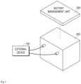
- FIG. 1 is a diagram showing a connection state in which an actual battery pack 200 is driven by interlocking with the external device 100.
- the battery inputs/outputs current/voltage while connected to an external device 100, which may be an electronic device acting as a load or a charging device that inputs a charging current into the battery, and the battery management unit 300 measures the voltage/current/temperature, and the like in real time, and performs an operation for protecting the battery.
- an external device 100 which may be an electronic device acting as a load or a charging device that inputs a charging current into the battery
- the battery management unit 300 measures the voltage/current/temperature, and the like in real time, and performs an operation for protecting the battery.
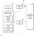
- FIG. 2 is a block diagram showing a battery pack simulation device according to an embodiment of the present invention.
- the battery pack simulation device 400 includes an input unit 410 that receives voltage values, current values, temperature, and initial impedance values, an output value generation unit 420 that generates an output value based on the input voltage value, current value, temperature, and initial impedance value, an output unit 430 that transmits the generated output value to the battery management unit 300, and a monitoring unit 440 that monitors the operation of the battery management unit 300.
- an input unit 410 that receives voltage values, current values, temperature, and initial impedance values
- an output value generation unit 420 that generates an output value based on the input voltage value, current value, temperature, and initial impedance value
- an output unit 430 that transmits the generated output value to the battery management unit 300
- a monitoring unit 440 that monitors the operation of the battery management unit 300.
- the input unit 410 is a component for inputting a voltage value, a current value, a temperature, and an initial impedance value of a battery pack to be simulated.
- a voltage value, a current value, a temperature, and an initial impedance value may be entered.
- Table 1 Time Voltage (mV) Current (mA) Temper ature (deg C) Initial impedance value (Ohm) T1 1200 0 25 1 T2 1200 500 25 1 T3 1200 1000 25 1 T4 3800 0 -20 1 T5 3800 -500 -20 1 T6 3800 -1000 -20 1
- a predetermined initial impedance value is inputted, and the initial impedance value varies over time in the impedance value variation unit 421 described later, so that it is set to simulate an impedance value that changes during actual battery operation.
- the input unit 410 has an interface connected to an input device such as a computer and a portable PDA device, and may receive data from these input devices and is equipped with a memory reader terminal and may receive input data from the memory such as a USB memory.
- the input data is composed of the voltage value, current value, temperature, and initial impedance value of the battery pack that may simulate a virtual battery and is data that simulates a specification of a battery to be simulated, a driving state and a driving condition of the battery, and is referred to as "virtual battery pack initial data" in the present invention.
- the output value generation unit 420 is a component that generates an output value that simulates measurement data of an actual battery based on initial data of a virtual battery pack received from the input unit 410.
- the output value outputted from the simulation device is transmitted to the battery management unit (BMU) 500 through the output unit 430.
- BMU battery management unit
- the received current value and temperature are outputted as they are, and the input voltage value and initial impedance value are converted through a predetermined process to generate an output value.
- These output values are 'virtual battery pack measurement data' that simulate voltage, current, temperature, and impedance measured during actual battery operation.
- the output value generation unit 420 includes an impedance value variation unit 421 for changing the received initial impedance value by a predetermined value at predetermined time intervals, and a voltage value recalculation unit 422 for recalculating a voltage value based on the input current value and the variable impedance value to change the impedance value and recalculate the voltage value accordingly.
- the impedance value variation unit 421 is configured to change an initial impedance value by a predetermined value at predetermined time intervals in order to simulate an impedance that fluctuates while the virtual battery is driven.
- BMU battery management unit
- the impedance value variation unit may increase by 1 milliohm (1m ⁇ ) per second, thereby increasing the impedance to 10 milliohms (10m ⁇ ).
- the voltage value recalculation unit 220 is a component that calculates a voltage in which impedance is reflected.
- an impedance value or a variation value thereof generated in an actual battery pack is reflected in a voltage. Accordingly, simulation according to voltage fluctuations of the actual battery pack is possible.
- the input voltage in Table 1 may be recalculated as shown in Table 2 below by the input initial impedance value.
- T1 and T4 are when the current is 0 and the voltage values at this time are initially 1200 and 3800, respectively
- T2 and T3 are when the battery current increases by 500 mA and 1000 mA, respectively
- T5 and T6 are when the battery current decreases by 500 mA and 1000 mA, respectively
- the voltage value recalculation unit 422 recalculates the voltage values at T2, T3, T5, and T6 to 1700 mV, 2200 mV, 3300 mV, and 2800 mV, respectively.
- Table 3 shows the case where the impedance of the battery is changed to 2 Ohm.
- Time Recalculati on Voltage Value (mV) Current (mA) Tempe rature (deg C) Variable Impedance Value (Ohm) T1 1200 0 25 2 T2 2200 500 25 2 T3 3200 1000 25 2 T4 3800 0 -20 2 T5 2800 -500 -20 2 T6 1800 -1000 -20 2
- the voltage value recalculation unit 422 recalculates voltage values of 2200 mV, 3200 mV, 2800 mV, and 1800 mV, respectively.
- the battery pack simulation device of the present invention simulates a state very similar to an actual operating state of a battery, that is, a state in which a voltage fluctuates due to a battery charging/discharging state and an impedance value of the battery and variations thereof.
- the battery pack simulation device of the present invention transmits a voltage similar to that of the actual battery pack to the battery management unit 300 compared to the conventional simulation device, so that it is possible to check whether the battery management unit 300 operates normally in a situation similar to that of an actual battery pack.
- the output unit 430 transmits the voltage, current, and temperature output values generated by the output value generation unit 420 to the battery management unit 300.
- the output unit 430 also transmits the voltage, current, temperature, and impedance values generated by the output value generation unit 420 to the monitoring unit 440 to be described later.
- the output unit 430 converts the data received from the output value generation unit 420 into an actual physical output value and outputs the actual physical output value to the battery management unit 300 so that the battery management unit 300 may recognize the actual physical output value.
- the output unit 430 converts information on a voltage value transmitted from the output value generation unit 420 into an actual voltage signal and outputs the actual voltage signal to the battery management unit 300.
- the current value is converted into an actual current signal so that the battery management unit 300 may receive the actual current signal
- the temperature value is also converted into the form of a signal received by the battery management unit 300 for temperature measurement and outputs the signal.
- the voltage and current output values simulating the actual voltage/current is output by configuring the power supply in the simulation device, and since the conventional battery management unit 300 calculates the temperature from the internal thermistor resistance measurement value and the conversion table, the output of the temperature value is converted into the thermistor input voltage value corresponding to the temperature and outputs the thermistor input voltage value.
- the simulation device of the present invention may have a temperature conversion value table corresponding to the thermistor voltage built into the battery management unit 300 to be tested in the internal memory device.
- the battery charge/discharge cutoff signal SG1 and the overcurrent/overvoltage cutoff control signal SG2 may be the same signal depending on the battery management unit 300 performing a test, and although the output pin number may vary depending on the protection IC constituting the battery management unit 300, but it is possible for a person skilled in the art to configure an interface unit for extracting the signals from the battery management unit 300 and inputting the signals to the monitoring unit 440 by conventional techniques.
- the monitoring unit 440 may include a protection condition determination unit, a comparison unit, and an error determination unit, and may determine whether the battery management unit 300 has an error through these.
- the comparison unit compares the overcurrent/overvoltage conditions determined by the protection condition determination unit, the charge/discharge cutoff condition satisfaction signal, the battery charge/discharge cutoff signal SG1, and the overcurrent/overvoltage cutoff control signal SG2 received from the battery management unit 300 to determine matching.
- the protection condition determination unit will determine that an overvoltage cutoff condition has occurred and generate a battery protection required signal, and at this time, when the battery management unit 300 operates normally, since the overvoltage cutoff control signal SG2 will be transmitted to the monitoring unit 440, so that in this case, the comparison unit compares both signals and transmits a normal determination signal to the error determination unit.
- the output values generated by the output value generation unit 420 are within the range in which the overvoltage cutoff protection operation should be performed among the battery pack protection operation, when the battery management unit 300 does not perform an overvoltage cutoff protection operation, it is determined that the battery management unit 300 does not operate normally.
- the battery charge/discharge cutoff signal SG1 is also compared in the comparison unit to determine whether the battery management unit 300 is normally operating in the same process.
- the protection condition determination unit and the battery management unit 300 each determine whether the battery protection condition is satisfied from the virtual battery pack measurement data, and generate a battery protection required signal and a battery control signal, and the comparison unit compares these two signals to determine whether the battery management unit 300 operates normally.
- the comparison unit also receives the calculation impedance value calculated from the battery management unit 300, and compares this with the variable impedance value outputted from the output value generation unit 420 to determine whether the battery management unit 300 operates normally.
- the battery management unit 300 calculates the battery impedance from the battery current/voltage value, and when the simulation device 400 of the present invention is connected, the impedance of the virtual battery is calculated from the current/voltage value inputted from the output unit 430 using an internal algorithm to calculate the calculated battery impedance value.
- the battery management unit 300 outputs the calculated battery impedance value as an impedance signal IM to the monitoring unit 440, and the comparison unit receives this and compares the calculated impedance value with the actual impedance value of the virtual battery received from the output value generation unit 420 to detect whether there is an abnormality in the impedance calculation internal algorithm of the battery management unit 300 and an error in the impedance calculation configuration of the battery management unit 300.
- the actual impedance value of the virtual battery is an impedance value varied in the impedance value variation unit 421 with respect to the initial impedance value given through the input unit 410, and is a value outputted from the output value generation unit 420 to the monitoring unit 440 along with corresponding current and voltage values by applying an impedance change as in an actual battery.
- the error determination unit determines whether or not the battery management unit 300 is normally operated according to the comparison result of the comparison unit.
- the error determination unit or the battery pack simulation device 400 may further include a display unit that displays a result of determining whether the normal operation is performed at a predetermined position.
- the monitoring unit 440 transmits a normal signal to the display unit, and the display unit outputs a display indicating the normal state, and if it is determined that the battery management unit 300 is not operating normally, the monitoring unit 440 may transmit a defective signal to the display unit, and the display unit may output a display indicating a defective state.
- the battery management unit 300 calculates the impedance value of the virtual battery based on the current/voltage value of the virtual battery generated by the output value generation unit 420 through the internal impedance calculation configuration of the battery management unit 300 for the corresponding virtual battery, and outputs the impedance signal IM to the monitoring unit 440.
- the battery management unit 300 receives a signal such as a current/voltage value inputted from an actual battery from the battery pack simulation device 400 of the present invention, and calculates an impedance value based on this and outputs it to the monitoring unit 440, so that the monitoring unit 440 determines whether the battery management unit 300 is abnormal by checking whether the battery management unit 300 has correctly calculated the impedance.
- a signal such as a current/voltage value inputted from an actual battery from the battery pack simulation device 400 of the present invention
- the battery management unit 300 generates a battery charge/discharge cutoff signal SG1 for preventing overcharge/overdischarge and an overcurrent/overvoltage cutoff control signal SG2 based on the current/voltage inputted from the output value generation unit 420, and transmits the signals to the monitoring unit 440.
- the battery management unit 300 receives a signal such as a current/voltage value inputted from an actual battery from the battery pack simulation device 400 of the present invention, and based on this, determines whether overcurrent/overvoltage, overcharge/overdischarge occurs to transmit the determination signal or control signal to the monitoring unit 440, and the monitoring unit 440 determines whether the battery charge/discharge cutoff signal SG1 and the overcurrent/overvoltage cutoff control signal SG2 transmitted from the battery management unit 300 are correctly generated to detect whether the battery management unit 300 is abnormal.
- a signal such as a current/voltage value inputted from an actual battery from the battery pack simulation device 400 of the present invention
- FIG. 3 is a flowchart illustrating a method of checking a battery management unit using a simulation device of a battery pack according to an embodiment of the present invention.
- the battery pack simulation method includes a battery pack data input step S100 of inputting the voltage, current, temperature, and initial impedance of the battery pack, an output value generation step S200 of generating an output value based on the input data, an output value transmission step S300 of transmitting the generated output value to the battery management unit 300 and a monitoring step S400 of monitoring whether the battery management unit 300 operates normally according to the transmitted output value.
- the battery pack data input step S100 is a process of inputting battery pack data, such as voltage value, current value, temperature, and initial impedance value of the battery pack to be simulated. This is achieved through the input unit 410 of the simulation device 400 of the present invention described above.
- the input data is composed of the voltage value, current value, temperature, and initial impedance value of the battery pack that may simulate a virtual battery and is data that implements a specification of a battery to be simulated, a driving state and a driving condition of the battery, and is referred to as virtual battery pack data.
- the virtual battery pack data input in the battery pack data input step S100 is transmitted to the output value generation unit 420, and is generated as an output value (virtual battery pack measurement data) through the output value generation step S200 described below.
- the output value generation step S200 is a process of generating virtual battery pack measurement data that is an output value outputted from the simulator based on the battery pack data input in the battery pack data input step S100.
- the battery pack data including voltage, current, temperature, and initial impedance values and outputs virtual battery pack measurement data, outputs the current value and temperature value inputted in the battery pack data input step S100 as it is, and the voltage and initial impedance values vary and output a recalculation voltage value obtained by recalculating a voltage value from the changed impedance value and the current value.
- the impedance value variation step S210 is a process of simulating that the impedance value of a virtual battery pack varies over time, and is a process of calculating a 'virtual impedance value' which is a changed impedance value by changing an initial impedance value inputted as battery pack data by a predetermined value at predetermined time intervals.
- the impedance values were changed by 1 for each of the initial impedance values in Table 1 in the intervals T1 to T3 and T4 to T5.
- the voltage value recalculation step S220 is a process of calculating a 'recalculation voltage' in which the virtual impedance value is reflected.
- the recalculation voltage is a 'virtual battery measurement voltage' that simulates the actual measurement voltage of a virtual battery.
- the output value transmission step S300 is a process of transmitting the output value of the output value generation unit 420 generated in the above-described output value generation step S200 to the battery management unit 300.
- the output value is virtual battery pack measurement data that simulates a voltage/current/temperature/impedance value of a battery during actual battery operation, and checks whether the battery management unit 300 operates normally.
- the monitoring step S400 is a process of monitoring whether the battery management unit 300 operates normally according to the output value generated in the output value generation step S200.
- the generated output values are within the range in which the overvoltage cutoff protection operation should be performed among the battery pack protection operation
- the battery management unit 300 when the battery management unit 300 normally performs the overvoltage cutoff protection operation, it is determined that the battery management unit 300 operates normally.
- the generated output values are within the range in which the overvoltage cutoff protection operation should be performed among the battery pack protection operation, when the battery management unit 300 does not perform an overvoltage cutoff protection operation, it is determined that the battery management unit 300 does not operate normally.
- the monitoring step S400 may include an impedance calculation function monitoring procedure, an overcharge/overdischarge control function monitoring procedure, and an overcurrent/overvoltage control function monitoring procedure as follows.
- the battery management unit 300 calculates the battery impedance from the battery current/voltage or current/voltage/temperature.
- the battery management unit 300 calculates a 'calculation impedance value' from a voltage/current or voltage/current/temperature value among virtual battery pack measurement data that is an output value outputted from the output unit 430 of the battery pack simulation device 400.
- the virtual battery pack measurement data includes a 'virtual impedance value' corresponding to the voltage/current or voltage/current/temperature value inputted to the battery management unit 300 generated in the output value generation step S200.
- the monitoring unit 440 of the battery pack simulation device 400 of the present invention receives the 'calculation impedance value' from the battery management unit 300, and receives the 'virtual impedance value' generated from the output value generation unit 420 in the same time interval in which the calculation impedance value is calculated to compare them with each other, so that it is monitored whether the impedance calculation function of the battery management unit 300 operates normally.
- the impedance calculation function of the battery management unit 300 When the 'calculation impedance value' and the 'virtual impedance value' match within a predetermined range, it is determined that the impedance calculation function of the battery management unit 300 operates normally, and otherwise, it is determined that the impedance calculation function of the battery management unit 300 does not operate normally.
- the battery management unit 300 needs to calculate an impedance value at T2 and transmit it to the monitoring unit 440, and if the calculated impedance value at T2 is not 2 Ohm, is the monitoring unit 440 determined that the impedance calculation function of the battery management unit 300 is abnormal.
- the battery management unit 300 performs a battery protection function based on the battery voltage/current measurement value.
- the monitoring procedure of the present invention includes a procedure for monitoring such a battery pack protection function, and this may include a protection function execution condition determination procedure in which the battery pack simulation device determines whether an execution condition of a battery protection function including at least one control among overcharge/overdischarge control or overvoltage/overcurrent control functions is satisfied from the virtual battery pack measurement data; a battery protection control signal receiving procedure in which the battery management unit receives a protection control signal for at least one control among the overcharge/overdischarge control or overvoltage/overcurrent control functions, which is generated from the virtual battery pack floor data; and a determination procedure for determining whether the battery protection function of the battery management unit normally operates based on whether the protection control signal is normally received when the protection function execution condition is satisfied.
- the battery pack protection function may include an overcharge/overdischarge control function and an overcurrent/overvoltage control function, and each of these will be described as follows.
- the battery management unit 300 measures the voltage of the battery, detects an overcharge/overdischarge state accordingly, and outputs a charge/discharge cutoff control signal to prevent this.
- the simulation device 400 of the present invention monitors whether a normal control signal is outputted under voltage conditions in which a control signal should be generated by receiving such a charge/discharge cutoff control signal from the battery management unit 300.
- This overcharge/overdischarge control function monitoring procedure receives the fluctuating voltage value outputted from the output value generation unit 420 by the monitoring unit 440, and determines whether the overcharge/overdischarge control is to be performed in the corresponding battery to be simulated and in the case of voltage section where overcharge/overdischarge control should be executed, determines whether a 'charge/discharge cutoff control signal' for the variable voltage value is received from the battery management unit 300 to determine whether the overcharge/overdischarge control function of the battery management unit 300 operates normally.
- the battery management unit 300 outputs a control signal for resolving an overcurrent/overvoltage condition with respect to an overcurrent/overvoltage condition of the battery.
- the simulation device 400 of the present invention monitors whether or not the battery management unit 300 normally generates such an overcurrent/overvoltage control signal.
- the monitoring unit 440 receives the fluctuating current/voltage value outputted from the output value generation unit 420, and determines whether the overvoltage/overcurrent control should be performed in the corresponding battery to be simulated, and in the case of a voltage/current section in which overvoltage/overcurrent control should be performed, determines whether an 'overvoltage/overcurrent cutoff control signal' is received from the battery management unit 300 to determine whether the overvoltage/overcurrent control function of the battery management unit 300 operates normally.
- the battery pack simulation device may be configured to further include a display step of displaying the test result.
- a normal signal is transmitted to the display unit, and the display unit outputs a display indicating a normal state
- the display unit may output a display indicating a defective state
Landscapes
- Engineering & Computer Science (AREA)
- Physics & Mathematics (AREA)
- General Physics & Mathematics (AREA)
- Manufacturing & Machinery (AREA)
- Chemical & Material Sciences (AREA)
- Chemical Kinetics & Catalysis (AREA)
- Electrochemistry (AREA)
- General Chemical & Material Sciences (AREA)
- General Engineering & Computer Science (AREA)
- Theoretical Computer Science (AREA)
- Microelectronics & Electronic Packaging (AREA)
- Computer Hardware Design (AREA)
- Evolutionary Computation (AREA)
- Geometry (AREA)
- Power Engineering (AREA)
- Secondary Cells (AREA)
- Tests Of Electric Status Of Batteries (AREA)
- Charge And Discharge Circuits For Batteries Or The Like (AREA)
Claims (10)
- Batteriepack-Simulationsvorrichtung (400), welche dazu eingerichtet ist, mit einer Batterieverwaltungseinheit (300) verbunden zu sein, um eine Funktion der Batterieverwaltungseinheit (300) zu überprüfen, wobei die Vorrichtung umfasst:eine Eingabeeinheit (410), welche dazu eingerichtet ist, Ausgangsdaten eines virtuellen Batteriepacks zu empfangen, umfassend einen Spannungswert, einen Stromwert und einen Ausgangsimpedanzwert;eine Ausgabewert-Erzeugungseinheit (420), welche dazu eingerichtet ist, auf Grundlage des empfangenen Spannungswertes, Stromwertes und Ausgangsimpedanzwertes virtueller Batteriepack-Messdaten zu erzeugen, umfassend einen Impedanzwert und einen Spannungswert, welche in Bezug auf eine virtuelle Batterie variieren;eine Ausgabeeinheit (430), welche dazu eingerichtet ist, wenigstens einen Teil der erzeugten virtueller Batteriepack-Messdaten an die Batterieverwaltungseinheit zu übertragen; undeine Überwachungseinheit (440), welche dazu eingerichtet ist, von der Batterieverwaltungseinheit eine vorbestimmte Information zu empfangen, welche auf die Funktion bezogen ist, und auf Grundlage der vorbestimmten Information zu überwachen, ob die Batterieverwaltungseinheit normal arbeitet,dadurch gekennzeichnet, dass die Ausgabewert-Erzeugungseinheit (420) umfasst:eine Impedanzwert-Variationseinheit (421), welche dazu eingerichtet ist, einen variablen Impedanzwert auszugeben, welcher durch Ändern des empfangenen Ausgangsimpedanzwertes um einen vorbestimmten Wert zu einem vorbestimmten Zeitintervall erhalten wird; undeine Spannungswert-Neuberechnungseinheit (422), welche dazu eingerichtet ist, auf Grundlage des eingegebenen Stromwertes und des variablen Impedanzwertes einen Spannungswert neu zu berechnen.
- Vorrichtung (400) nach Anspruch 1, wobei die virtueller Batteriepack-Messdaten den neuberechneten Spannungswert und den eingegebenen Stromwert als einen virtuellen Messspannungswert bzw. einen virtuellen Messstromwert umfassen,
wobei die Überwachungseinheit (440) einen Berechnung-Impedanzwert empfängt, welcher auf Grundlage des virtuellen Messspannungswertes und des virtuellen Messstromwertes durch die Batterieverwaltungseinheit (300) berechnet ist. - Vorrichtung (400) nach Anspruch 2, wobei die Überwachungseinheit (440) ferner eine Vergleichseinheit zum Vergleichen des variablen Impedanzwertes und des Berechnung-Impedanzwertes umfasst.
- Vorrichtung nach Anspruch 2, wobei die Überwachungseinheit (440) ein Batteriesteuersignal empfängt, welches durch die Batterieverwaltungseinheit (300) aus dem virtuellen Messspannungswert und dem virtuellen Messstromwert erzeugt worden ist.
- Vorrichtung (400) nach Anspruch 4, wobei die Überwachungseinheit (440) ferner umfasst:eine Schutzbedingung-Bestimmungseinheit, welche dazu eingerichtet ist, aus den virtueller Batteriepack-Messdaten zu bestimmen, ob eine Batterie-Schutzbedingung erfüllt ist, und ein erforderliches Batterieschutzsignal zu erzeugen, undeine Vergleichseinheit, welche dazu eingerichtet ist, das von der Batterieverwaltungseinheit empfangene Batteriesteuersignal mit dem erforderlichen Batterieschutzsignal zu vergleichen.
- Vorrichtung (400) nach Anspruch 3 oder 5, wobei ein normales oder abnormales Betriebssignal der Batterieverwaltungseinheit (300) gemäß einem Vergleichsergebnis der Vergleichseinheit ausgegeben wird.
- Verfahren eines Überprüfens einer Funktion einer Batterieverwaltungseinheit (300) unter Verwendung einer Batteriepack-Simulationsvorrichtung (400), wobei das Verfahren umfasst:einen Batteriepackdaten-Eingabeschritt (S100) eines Eingebens von Batteriepackdaten, umfassend Spannung, Strom, Temperatur und Ausgangsimpedanzwert eines Batteriepacks in die Batteriepack-Simulationsvorrichtung;einen Ausgabewert-Erzeugungsschritt (S200) eines Erzeugens virtueller Batteriepack-Messdaten auf Grundlage der Batteriepackdaten, welche in die Batteriepack-Simulationsvorrichtung eingegeben werden;einen Ausgabewert-Übertragungsschritt (S300) eines Übertragens des erzeugten Ausgabewertes von der Batteriepack-Simulationsvorrichtung an die Batterieverwaltungseinheit; undeinen Überwachungsschritt (S400) eines Überwachens in der Batteriepack-Simulationsvorrichtung, ob die Batterieverwaltungseinheit normal arbeitet,dadurch gekennzeichnet, dass der Ausgabewert-Erzeugungsschritt umfasst:einen Impedanzwert-Variationsschritt (S210) eines Erzeugens eines virtuellen Impedanzwertes durch Ändern des empfangenen Ausgangsimpedanzwertes um einen vorbestimmten Wert zu einem vorbestimmten Zeitintervall; undeinen Spannungswert-Neuberechnungsschritt (S220) eines Berechnens einer virtueller Batteriepack-Messspannung durch Neuberechnen eines Spannungswertes auf Grundlage des empfangenen Stromwertes der Batteriepackdaten und des virtuellen Impedanzwertes.
- Verfahren nach Anspruch 7, wobei, wenn die Batteriesimulationsvorrichtung den Betrieb der Batterieverwaltungseinheit (300) überwacht,
der Überwachungsschritt (S400) ein normales Signal ausgibt, wenn die Batterieverwaltungseinheit einen Batteriepack-Schutzbetrieb normal durchführt, und ein Fehlersignal ausgibt, wenn die Batterieverwaltungseinheit den Batteriepack-Schutzbetrieb nicht normal durchführt. - Verfahren nach Anspruch 7, wobei der Überwachungsschritt (S400) umfasst:einen Schritt eines Empfangens, durch die Batteriepack-Simulationsvorrichtung (400), eines Berechnung-Impedanzwertes, welcher durch die Batterieverwaltungseinheit (300) aus der virtuellen Batteriemessspannung berechnet wird; undeinen Impedanzberechnungsfunktion-Überwachungsschritt eines Vergleichens des virtuellen Impedanzwertes, welcher der virtuellen Batteriemessspannung entspricht, mit dem Berechnung-Impedanzwert, um zu bestimmen, ob eine Impedanzberechnungsfunktion der Batterieverwaltungseinheit (300) normal arbeitet.
- Verfahren nach Anspruch 7, wobei der Überwachungsschritt umfasst:durch die Batteriepack-Simulationsvorrichtung (400),einen Bestimmungsvorgang einer Schutzfunktion-Ausführungsbedingung zum Bestimmen, ob eine Ausführungsbedingung einer Batterieschutzfunktion, umfassend wenigstens eines aus einer Überladung/Überentladung-Steuerung oder Überspannung/Überstrom-Steuerungsfunktionen, aus den virtueller Batteriepack-Messdaten erfüllt ist;einen Empfangsvorgang eines Batterieschutz-Steuersignals zum Empfangen eines Schutzsteuersignals für wenigstens eine Steuerung aus der Überladung/Überentladung-Steuerung oder den Überspannung/Überstrom-Steuerungsfunktionen, welche durch die Batterieverwaltungseinheit (300) erzeugt werden, aus den virtueller Batteriepack-Messdaten; undeinen Bestimmungsvorgang eines Bestimmens, ob die Batterieschutzfunktion der Batterieverwaltungseinheit (300) normal arbeitet, auf Grundlage darauf, ob das Schutzsteuersignal normal erhalten wird, wenn eine Schutzfunktion-Ausführungsbedingung erfüllt ist.
Applications Claiming Priority (3)
| Application Number | Priority Date | Filing Date | Title |
|---|---|---|---|
| KR20200011365 | 2020-01-30 | ||
| KR1020200162970A KR102777825B1 (ko) | 2020-01-30 | 2020-11-27 | 배터리 팩 시뮬레이션 장치 및 이를 이용한 배터리 관리유닛 점검 방법 |
| PCT/KR2021/001047 WO2021153976A1 (ko) | 2020-01-30 | 2021-01-27 | 배터리 팩 시뮬레이션 장치 및 이를 이용한 배터리 관리유닛 점검 방법 |
Publications (3)
| Publication Number | Publication Date |
|---|---|
| EP4016097A1 EP4016097A1 (de) | 2022-06-22 |
| EP4016097A4 EP4016097A4 (de) | 2022-11-30 |
| EP4016097B1 true EP4016097B1 (de) | 2025-03-12 |
Family
ID=77079607
Family Applications (1)
| Application Number | Title | Priority Date | Filing Date |
|---|---|---|---|
| EP21747249.7A Active EP4016097B1 (de) | 2020-01-30 | 2021-01-27 | Vorrichtung zur simulation eines batteriepacks und verfahren zur prüfung der batterieverwaltungseinheit unter verwendung derselben |
Country Status (7)
| Country | Link |
|---|---|
| US (1) | US12228606B2 (de) |
| EP (1) | EP4016097B1 (de) |
| JP (1) | JP7271787B2 (de) |
| CN (1) | CN114270203B (de) |
| ES (1) | ES3017562T3 (de) |
| HU (1) | HUE070834T2 (de) |
| WO (1) | WO2021153976A1 (de) |
Families Citing this family (1)
| Publication number | Priority date | Publication date | Assignee | Title |
|---|---|---|---|---|
| CN114966514B (zh) * | 2022-07-28 | 2022-11-01 | 武汉海亿新能源科技有限公司 | 一种燃料电池单片电压信号发生器及其控制方法 |
Family Cites Families (39)
| Publication number | Priority date | Publication date | Assignee | Title |
|---|---|---|---|---|
| US6081100A (en) * | 1999-05-20 | 2000-06-27 | Guthrie; Dennis Lynn | Method for simulating behavior of batteries |
| US6204647B1 (en) * | 1999-06-02 | 2001-03-20 | Keithley Instruments, Inc. | Battery emulating power supply |
| JP2007195360A (ja) | 2006-01-20 | 2007-08-02 | Toyota Motor Corp | ハイブリッドシステムの試験装置及びそれに用いられる電源装置 |
| EP1892536B1 (de) | 2006-08-22 | 2012-04-11 | Delphi Technologies, Inc. | Batterieüberwachungssystem |
| KR100823507B1 (ko) * | 2006-08-29 | 2008-04-21 | 삼성에스디아이 주식회사 | 배터리 관리 시스템 및 그 구동방법 |
| CN101394096B (zh) | 2007-09-19 | 2010-12-22 | 比亚迪股份有限公司 | 电池组模拟器 |
| JP2009099389A (ja) * | 2007-10-17 | 2009-05-07 | Yokogawa Electric Corp | 燃料電池シミュレータおよび燃料電池のシミュレーション方法 |
| AT10763U3 (de) | 2009-05-12 | 2010-08-15 | Avl List Gmbh | Verfahren und prüfstand zum prüfen von hybrid-antriebssystemen oder teilkomponenten davon |
| JP2010286388A (ja) | 2009-06-12 | 2010-12-24 | Yokogawa Electric Corp | 電池特性模擬装置 |
| JP2011038928A (ja) | 2009-08-12 | 2011-02-24 | Yokogawa Electric Corp | 電池特性模擬装置 |
| WO2011066540A2 (en) * | 2009-11-30 | 2011-06-03 | Forward Thinking Products, Llc | Battery emulator and methods of use |
| CN101762800B (zh) | 2010-01-28 | 2013-04-03 | 北京航空航天大学 | 电池组管理系统测试平台 |
| JP4689756B1 (ja) * | 2010-03-31 | 2011-05-25 | 古河電気工業株式会社 | 電池内部状態推定装置および電池内部状態推定方法 |
| KR101101947B1 (ko) * | 2010-09-12 | 2012-01-02 | 주식회사 브이앤아이 | 배터리 관리시스템의 배터리 시뮬레이터 |
| CN102467091B (zh) | 2010-11-11 | 2017-03-01 | 帝斯贝思数字信号处理和控制工程有限公司 | 具有故障仿真的电池模拟设备及方法 |
| US20170234933A9 (en) * | 2011-01-19 | 2017-08-17 | Sendyne Corporation | Converging algorithm for real-time battery prediction |
| US9608297B2 (en) | 2011-11-16 | 2017-03-28 | Datang Nxp Semiconductors Co., Ltd. | In-cell battery management device |
| TWI476978B (zh) * | 2012-04-11 | 2015-03-11 | Ship & Ocean Ind R & D Ct | 高電壓電池充電模擬系統及其運作方法 |
| KR20140073627A (ko) | 2012-11-30 | 2014-06-17 | 주식회사 포스코아이씨티 | 배터리 관리 장치 및 방법 |
| KR101603625B1 (ko) | 2013-03-21 | 2016-03-15 | 주식회사 엘지화학 | Bmu를 테스트하는 배터리 시뮬레이션 장치 및 배터리 시뮬레이션 방법 |
| KR101893957B1 (ko) * | 2013-08-19 | 2018-08-31 | 삼성에스디아이 주식회사 | 배터리 팩, 배터리 팩을 포함하는 장치, 및 배터리 팩의 관리 방법 |
| US10393813B2 (en) * | 2013-08-27 | 2019-08-27 | The Regents Of The University Of Michigan | On-board state of health monitoring of batteries using incremental capacity analysis |
| KR101650415B1 (ko) | 2013-10-14 | 2016-08-23 | 주식회사 엘지화학 | 하이브리드 이차 전지의 전압 추정 장치 및 그 방법 |
| TWI525330B (zh) | 2013-10-28 | 2016-03-11 | 仁寶電腦工業股份有限公司 | 電池模擬裝置 |
| KR101748644B1 (ko) | 2014-12-08 | 2017-06-19 | 주식회사 엘지화학 | 배터리 모듈 시뮬레이션 장치 |
| KR20160077689A (ko) * | 2014-12-24 | 2016-07-04 | 주식회사 엘지화학 | Bms 시뮬레이션 장치 |
| KR101785537B1 (ko) | 2015-02-26 | 2017-10-16 | 주식회사 엘지화학 | 이차 전지 관리 장치의 기능 검증 시스템 |
| CN104820200B (zh) | 2015-05-14 | 2018-07-06 | 哈尔滨冠拓电源设备有限公司 | 具有自检功能的电池管理系统功能检验平台及自检方法和检验方法 |
| KR101761023B1 (ko) * | 2015-11-18 | 2017-08-04 | 주식회사 포스코아이씨티 | 배터리 모의 장치, 모의 방법 및 이를 이용한 모의 시스템 |
| CN105759221A (zh) | 2016-04-29 | 2016-07-13 | 赵建和 | 一种带有内阻监测功能的动力电池组管理系统 |
| KR20180006264A (ko) * | 2016-07-07 | 2018-01-17 | 주식회사 포스코아이씨티 | 배터리 모의 장치 및 배터리 모의 방법 |
| JP6737022B2 (ja) | 2016-07-15 | 2020-08-05 | 日立化成株式会社 | シミュレーション方法及びシミュレーション装置 |
| CN107167677B (zh) | 2017-04-27 | 2020-08-14 | 广东机电职业技术学院 | 用于电池管理系统的模拟测试装置及测试方法 |
| US10809307B2 (en) | 2017-09-26 | 2020-10-20 | E-Xteq Europe | Differential battery testers |
| CN108548968A (zh) * | 2018-03-06 | 2018-09-18 | 湖南小步科技有限公司 | 电池管理系统的性能测试装置及测试方法 |
| KR102589362B1 (ko) | 2018-04-04 | 2023-10-12 | 주식회사 엘지에너지솔루션 | Bms 모니터링 장치 및 방법 |
| CN108680803B (zh) | 2018-05-04 | 2020-09-18 | 武汉精立电子技术有限公司 | 支持bms主动均衡功能测试的电池模拟系统及方法 |
| CN108627723B (zh) * | 2018-05-04 | 2020-06-12 | 武汉精立电子技术有限公司 | 用于bms测试的电池模拟装置及方法 |
| KR102059381B1 (ko) * | 2018-08-03 | 2019-12-26 | (사)캠틱종합기술원 | Bms 시뮬레이터 및 bms 시뮬레이션 시스템 |
-
2021
- 2021-01-27 HU HUE21747249A patent/HUE070834T2/hu unknown
- 2021-01-27 WO PCT/KR2021/001047 patent/WO2021153976A1/ko not_active Ceased
- 2021-01-27 US US17/769,380 patent/US12228606B2/en active Active
- 2021-01-27 ES ES21747249T patent/ES3017562T3/es active Active
- 2021-01-27 JP JP2022510190A patent/JP7271787B2/ja active Active
- 2021-01-27 EP EP21747249.7A patent/EP4016097B1/de active Active
- 2021-01-27 CN CN202180004896.9A patent/CN114270203B/zh active Active
Also Published As
| Publication number | Publication date |
|---|---|
| WO2021153976A1 (ko) | 2021-08-05 |
| EP4016097A4 (de) | 2022-11-30 |
| JP2022545410A (ja) | 2022-10-27 |
| US20240027517A1 (en) | 2024-01-25 |
| CN114270203A (zh) | 2022-04-01 |
| US12228606B2 (en) | 2025-02-18 |
| CN114270203B (zh) | 2024-04-19 |
| EP4016097A1 (de) | 2022-06-22 |
| ES3017562T3 (en) | 2025-05-13 |
| JP7271787B2 (ja) | 2023-05-11 |
| HUE070834T2 (hu) | 2025-07-28 |
Similar Documents
| Publication | Publication Date | Title |
|---|---|---|
| US11853044B2 (en) | Test equipment and test method of battery management system | |
| US8957639B2 (en) | Event system and timekeeping for battery management and protection system | |
| US12467966B2 (en) | Apparatus and method for diagnosing insulation resistance measurement circuit | |
| US11846678B2 (en) | Method and system for validating a temperature sensor in a battery cell | |
| US20120166918A1 (en) | Verification of Configuration Parameters | |
| US9172265B2 (en) | Battery charger, voltage monitoring device and self-diagnosis method of reference voltage circuit | |
| KR102762567B1 (ko) | 전지 시스템 내 온도 센서의 검증을 위한 방법 및 시스템 | |
| KR20190075609A (ko) | 전류 센서 진단 장치 및 방법 | |
| CN113631938B (zh) | 用于检测并联电池单元的连接故障的方法和系统 | |
| US8890536B2 (en) | Secondary battery with apparatus for checking the state of a service plug | |
| CN110945369B (zh) | 充电装置的测试系统和方法 | |
| EP4016097B1 (de) | Vorrichtung zur simulation eines batteriepacks und verfahren zur prüfung der batterieverwaltungseinheit unter verwendung derselben | |
| KR20230084925A (ko) | 배터리 상태 모니터링 장치 및 방법, 그리고 배터리 보호 장치 | |
| KR102777825B1 (ko) | 배터리 팩 시뮬레이션 장치 및 이를 이용한 배터리 관리유닛 점검 방법 | |
| CN113646648A (zh) | 检测并联电池单元的连接故障的方法和系统 | |
| US20250389682A1 (en) | Apparatus and method for detecting foreign substance | |
| US20240063647A1 (en) | Battery Management Apparatus and Method | |
| CN120584291A (zh) | 电池诊断设备和电池诊断方法 | |
| EP3923008B1 (de) | Verfahren und vorrichtung zur messung des elektrischen stroms eines batteriesystems | |
| EP4600679A1 (de) | Vorrichtung und verfahren zur diagnose einer batterieanordnung | |
| KR20250120777A (ko) | 시험 장치 및 시험 방법 | |
| KR20250060482A (ko) | 배터리 진단 장치 및 이의 동작 방법 | |
| KR20250052891A (ko) | 진단 장치 및 이를 포함하는 배터리 팩 | |
| KR20250109441A (ko) | 배터리 진단 장치 및 이의 동작 방법 | |
| KR20250014991A (ko) | 배터리 진단 장치 및 이의 동작 방법 |
Legal Events
| Date | Code | Title | Description |
|---|---|---|---|
| STAA | Information on the status of an ep patent application or granted ep patent |
Free format text: STATUS: THE INTERNATIONAL PUBLICATION HAS BEEN MADE |
|
| PUAI | Public reference made under article 153(3) epc to a published international application that has entered the european phase |
Free format text: ORIGINAL CODE: 0009012 |
|
| STAA | Information on the status of an ep patent application or granted ep patent |
Free format text: STATUS: REQUEST FOR EXAMINATION WAS MADE |
|
| 17P | Request for examination filed |
Effective date: 20220316 |
|
| AK | Designated contracting states |
Kind code of ref document: A1 Designated state(s): AL AT BE BG CH CY CZ DE DK EE ES FI FR GB GR HR HU IE IS IT LI LT LU LV MC MK MT NL NO PL PT RO RS SE SI SK SM TR |
|
| REG | Reference to a national code |
Ref country code: DE Ref legal event code: R079 Free format text: PREVIOUS MAIN CLASS: G01R0031280000 Ipc: G01R0035000000 Ref country code: DE Ref legal event code: R079 Ref document number: 602021027539 Country of ref document: DE Free format text: PREVIOUS MAIN CLASS: G01R0031280000 Ipc: G01R0035000000 |
|
| A4 | Supplementary search report drawn up and despatched |
Effective date: 20221027 |
|
| RIC1 | Information provided on ipc code assigned before grant |
Ipc: H02H 7/18 20060101ALI20221021BHEP Ipc: G01R 31/389 20190101ALI20221021BHEP Ipc: G01R 31/3842 20190101ALI20221021BHEP Ipc: G01R 35/00 20060101AFI20221021BHEP |
|
| DAV | Request for validation of the european patent (deleted) | ||
| DAX | Request for extension of the european patent (deleted) | ||
| GRAP | Despatch of communication of intention to grant a patent |
Free format text: ORIGINAL CODE: EPIDOSNIGR1 |
|
| STAA | Information on the status of an ep patent application or granted ep patent |
Free format text: STATUS: GRANT OF PATENT IS INTENDED |
|
| RIC1 | Information provided on ipc code assigned before grant |
Ipc: H02H 7/18 20060101ALI20241007BHEP Ipc: G01R 31/389 20190101ALI20241007BHEP Ipc: G01R 31/3842 20190101ALI20241007BHEP Ipc: G01R 35/00 20060101AFI20241007BHEP |
|
| INTG | Intention to grant announced |
Effective date: 20241018 |
|
| P01 | Opt-out of the competence of the unified patent court (upc) registered |
Free format text: CASE NUMBER: APP_59660/2024 Effective date: 20241104 |
|
| GRAS | Grant fee paid |
Free format text: ORIGINAL CODE: EPIDOSNIGR3 |
|
| GRAA | (expected) grant |
Free format text: ORIGINAL CODE: 0009210 |
|
| STAA | Information on the status of an ep patent application or granted ep patent |
Free format text: STATUS: THE PATENT HAS BEEN GRANTED |
|
| AK | Designated contracting states |
Kind code of ref document: B1 Designated state(s): AL AT BE BG CH CY CZ DE DK EE ES FI FR GB GR HR HU IE IS IT LI LT LU LV MC MK MT NL NO PL PT RO RS SE SI SK SM TR |
|
| REG | Reference to a national code |
Ref country code: GB Ref legal event code: FG4D |
|
| REG | Reference to a national code |
Ref country code: CH Ref legal event code: EP |
|
| REG | Reference to a national code |
Ref country code: DE Ref legal event code: R096 Ref document number: 602021027539 Country of ref document: DE |
|
| REG | Reference to a national code |
Ref country code: IE Ref legal event code: FG4D |
|
| REG | Reference to a national code |
Ref country code: ES Ref legal event code: FG2A Ref document number: 3017562 Country of ref document: ES Kind code of ref document: T3 Effective date: 20250513 |
|
| PG25 | Lapsed in a contracting state [announced via postgrant information from national office to epo] |
Ref country code: RS Free format text: LAPSE BECAUSE OF FAILURE TO SUBMIT A TRANSLATION OF THE DESCRIPTION OR TO PAY THE FEE WITHIN THE PRESCRIBED TIME-LIMIT Effective date: 20250612 |
|
| PG25 | Lapsed in a contracting state [announced via postgrant information from national office to epo] |
Ref country code: FI Free format text: LAPSE BECAUSE OF FAILURE TO SUBMIT A TRANSLATION OF THE DESCRIPTION OR TO PAY THE FEE WITHIN THE PRESCRIBED TIME-LIMIT Effective date: 20250312 |
|
| REG | Reference to a national code |
Ref country code: LT Ref legal event code: MG9D |
|
| PG25 | Lapsed in a contracting state [announced via postgrant information from national office to epo] |
Ref country code: NO Free format text: LAPSE BECAUSE OF FAILURE TO SUBMIT A TRANSLATION OF THE DESCRIPTION OR TO PAY THE FEE WITHIN THE PRESCRIBED TIME-LIMIT Effective date: 20250612 |
|
| PG25 | Lapsed in a contracting state [announced via postgrant information from national office to epo] |
Ref country code: HR Free format text: LAPSE BECAUSE OF FAILURE TO SUBMIT A TRANSLATION OF THE DESCRIPTION OR TO PAY THE FEE WITHIN THE PRESCRIBED TIME-LIMIT Effective date: 20250312 |
|
| REG | Reference to a national code |
Ref country code: NL Ref legal event code: MP Effective date: 20250312 |
|
| PG25 | Lapsed in a contracting state [announced via postgrant information from national office to epo] |
Ref country code: LV Free format text: LAPSE BECAUSE OF FAILURE TO SUBMIT A TRANSLATION OF THE DESCRIPTION OR TO PAY THE FEE WITHIN THE PRESCRIBED TIME-LIMIT Effective date: 20250312 |
|
| PG25 | Lapsed in a contracting state [announced via postgrant information from national office to epo] |
Ref country code: BG Free format text: LAPSE BECAUSE OF FAILURE TO SUBMIT A TRANSLATION OF THE DESCRIPTION OR TO PAY THE FEE WITHIN THE PRESCRIBED TIME-LIMIT Effective date: 20250312 Ref country code: GR Free format text: LAPSE BECAUSE OF FAILURE TO SUBMIT A TRANSLATION OF THE DESCRIPTION OR TO PAY THE FEE WITHIN THE PRESCRIBED TIME-LIMIT Effective date: 20250613 |
|
| REG | Reference to a national code |
Ref country code: HU Ref legal event code: AG4A Ref document number: E070834 Country of ref document: HU |
|
| REG | Reference to a national code |
Ref country code: AT Ref legal event code: MK05 Ref document number: 1775420 Country of ref document: AT Kind code of ref document: T Effective date: 20250312 |
|
| PG25 | Lapsed in a contracting state [announced via postgrant information from national office to epo] |
Ref country code: NL Free format text: LAPSE BECAUSE OF FAILURE TO SUBMIT A TRANSLATION OF THE DESCRIPTION OR TO PAY THE FEE WITHIN THE PRESCRIBED TIME-LIMIT Effective date: 20250312 |
|
| PG25 | Lapsed in a contracting state [announced via postgrant information from national office to epo] |
Ref country code: SE Free format text: LAPSE BECAUSE OF FAILURE TO SUBMIT A TRANSLATION OF THE DESCRIPTION OR TO PAY THE FEE WITHIN THE PRESCRIBED TIME-LIMIT Effective date: 20250312 |
|
| PG25 | Lapsed in a contracting state [announced via postgrant information from national office to epo] |
Ref country code: SM Free format text: LAPSE BECAUSE OF FAILURE TO SUBMIT A TRANSLATION OF THE DESCRIPTION OR TO PAY THE FEE WITHIN THE PRESCRIBED TIME-LIMIT Effective date: 20250312 |
|
| PG25 | Lapsed in a contracting state [announced via postgrant information from national office to epo] |
Ref country code: PT Free format text: LAPSE BECAUSE OF FAILURE TO SUBMIT A TRANSLATION OF THE DESCRIPTION OR TO PAY THE FEE WITHIN THE PRESCRIBED TIME-LIMIT Effective date: 20250714 |
|
| PG25 | Lapsed in a contracting state [announced via postgrant information from national office to epo] |
Ref country code: IT Free format text: LAPSE BECAUSE OF FAILURE TO SUBMIT A TRANSLATION OF THE DESCRIPTION OR TO PAY THE FEE WITHIN THE PRESCRIBED TIME-LIMIT Effective date: 20250312 Ref country code: PL Free format text: LAPSE BECAUSE OF FAILURE TO SUBMIT A TRANSLATION OF THE DESCRIPTION OR TO PAY THE FEE WITHIN THE PRESCRIBED TIME-LIMIT Effective date: 20250312 |
|
| PG25 | Lapsed in a contracting state [announced via postgrant information from national office to epo] |
Ref country code: AT Free format text: LAPSE BECAUSE OF FAILURE TO SUBMIT A TRANSLATION OF THE DESCRIPTION OR TO PAY THE FEE WITHIN THE PRESCRIBED TIME-LIMIT Effective date: 20250312 |
|
| PG25 | Lapsed in a contracting state [announced via postgrant information from national office to epo] |
Ref country code: CZ Free format text: LAPSE BECAUSE OF FAILURE TO SUBMIT A TRANSLATION OF THE DESCRIPTION OR TO PAY THE FEE WITHIN THE PRESCRIBED TIME-LIMIT Effective date: 20250312 Ref country code: EE Free format text: LAPSE BECAUSE OF FAILURE TO SUBMIT A TRANSLATION OF THE DESCRIPTION OR TO PAY THE FEE WITHIN THE PRESCRIBED TIME-LIMIT Effective date: 20250312 |
|
| PG25 | Lapsed in a contracting state [announced via postgrant information from national office to epo] |
Ref country code: RO Free format text: LAPSE BECAUSE OF FAILURE TO SUBMIT A TRANSLATION OF THE DESCRIPTION OR TO PAY THE FEE WITHIN THE PRESCRIBED TIME-LIMIT Effective date: 20250312 |
|
| PG25 | Lapsed in a contracting state [announced via postgrant information from national office to epo] |
Ref country code: SK Free format text: LAPSE BECAUSE OF FAILURE TO SUBMIT A TRANSLATION OF THE DESCRIPTION OR TO PAY THE FEE WITHIN THE PRESCRIBED TIME-LIMIT Effective date: 20250312 |
|
| PG25 | Lapsed in a contracting state [announced via postgrant information from national office to epo] |
Ref country code: IS Free format text: LAPSE BECAUSE OF FAILURE TO SUBMIT A TRANSLATION OF THE DESCRIPTION OR TO PAY THE FEE WITHIN THE PRESCRIBED TIME-LIMIT Effective date: 20250712 |
|
| REG | Reference to a national code |
Ref country code: DE Ref legal event code: R097 Ref document number: 602021027539 Country of ref document: DE |
|
| PGFP | Annual fee paid to national office [announced via postgrant information from national office to epo] |
Ref country code: GB Payment date: 20251222 Year of fee payment: 6 |
|
| PG25 | Lapsed in a contracting state [announced via postgrant information from national office to epo] |
Ref country code: DK Free format text: LAPSE BECAUSE OF FAILURE TO SUBMIT A TRANSLATION OF THE DESCRIPTION OR TO PAY THE FEE WITHIN THE PRESCRIBED TIME-LIMIT Effective date: 20250312 |
|
| PGFP | Annual fee paid to national office [announced via postgrant information from national office to epo] |
Ref country code: FR Payment date: 20251223 Year of fee payment: 6 |
|
| PGFP | Annual fee paid to national office [announced via postgrant information from national office to epo] |
Ref country code: BE Payment date: 20251229 Year of fee payment: 6 |
|
| PLBE | No opposition filed within time limit |
Free format text: ORIGINAL CODE: 0009261 |
|
| STAA | Information on the status of an ep patent application or granted ep patent |
Free format text: STATUS: NO OPPOSITION FILED WITHIN TIME LIMIT |
|
| REG | Reference to a national code |
Ref country code: CH Ref legal event code: L10 Free format text: ST27 STATUS EVENT CODE: U-0-0-L10-L00 (AS PROVIDED BY THE NATIONAL OFFICE) Effective date: 20260121 |