EP4016082A1 - Verfahren und vorrichtung zum detektieren einer präsenz eines fluoreszenzmustertyps auf einem organschnitt mittels immunfluoreszenzmikroskopie - Google Patents
Verfahren und vorrichtung zum detektieren einer präsenz eines fluoreszenzmustertyps auf einem organschnitt mittels immunfluoreszenzmikroskopie Download PDFInfo
- Publication number
- EP4016082A1 EP4016082A1 EP21195352.6A EP21195352A EP4016082A1 EP 4016082 A1 EP4016082 A1 EP 4016082A1 EP 21195352 A EP21195352 A EP 21195352A EP 4016082 A1 EP4016082 A1 EP 4016082A1
- Authority
- EP
- European Patent Office
- Prior art keywords
- fluorescence
- information
- basis
- pattern type
- fluorescence image
- Prior art date
- Legal status (The legal status is an assumption and is not a legal conclusion. Google has not performed a legal analysis and makes no representation as to the accuracy of the status listed.)
- Granted
Links
- 210000000056 organ Anatomy 0.000 title claims abstract description 102
- 238000000034 method Methods 0.000 title claims abstract description 51
- 238000010820 immunofluorescence microscopy Methods 0.000 title claims abstract description 12
- 238000002073 fluorescence micrograph Methods 0.000 claims abstract description 102
- 230000011218 segmentation Effects 0.000 claims abstract description 90
- 238000013528 artificial neural network Methods 0.000 claims abstract description 56
- 238000012545 processing Methods 0.000 claims abstract description 37
- 239000013610 patient sample Substances 0.000 claims abstract description 22
- 239000007850 fluorescent dye Substances 0.000 claims abstract description 19
- 230000015572 biosynthetic process Effects 0.000 claims abstract description 13
- 239000007788 liquid Substances 0.000 claims abstract description 4
- 239000012895 dilution Substances 0.000 claims description 16
- 238000010790 dilution Methods 0.000 claims description 16
- 238000011534 incubation Methods 0.000 claims description 9
- 238000004590 computer program Methods 0.000 claims description 5
- 230000008569 process Effects 0.000 claims description 3
- 238000010186 staining Methods 0.000 claims description 2
- 230000006870 function Effects 0.000 description 7
- 230000003287 optical effect Effects 0.000 description 7
- 101150080085 SEG1 gene Proteins 0.000 description 6
- 101100421134 Schizosaccharomyces pombe (strain 972 / ATCC 24843) sle1 gene Proteins 0.000 description 6
- 239000000758 substrate Substances 0.000 description 6
- 210000004877 mucosa Anatomy 0.000 description 5
- 238000012549 training Methods 0.000 description 5
- 101100202858 Saccharomyces cerevisiae (strain ATCC 204508 / S288c) SEG2 gene Proteins 0.000 description 4
- 230000004913 activation Effects 0.000 description 4
- 238000004519 manufacturing process Methods 0.000 description 4
- 238000011176 pooling Methods 0.000 description 4
- 230000005855 radiation Effects 0.000 description 4
- 239000000523 sample Substances 0.000 description 4
- 238000004458 analytical method Methods 0.000 description 3
- 239000000427 antigen Substances 0.000 description 3
- 102000036639 antigens Human genes 0.000 description 3
- 108091007433 antigens Proteins 0.000 description 3
- 230000001419 dependent effect Effects 0.000 description 3
- 230000000694 effects Effects 0.000 description 3
- 230000005284 excitation Effects 0.000 description 3
- 210000004400 mucous membrane Anatomy 0.000 description 3
- 238000004448 titration Methods 0.000 description 3
- 230000008901 benefit Effects 0.000 description 2
- 210000004369 blood Anatomy 0.000 description 2
- 239000008280 blood Substances 0.000 description 2
- 238000001514 detection method Methods 0.000 description 2
- 210000003205 muscle Anatomy 0.000 description 2
- 210000002966 serum Anatomy 0.000 description 2
- 239000000243 solution Substances 0.000 description 2
- 210000002784 stomach Anatomy 0.000 description 2
- 238000003860 storage Methods 0.000 description 2
- 210000004876 tela submucosa Anatomy 0.000 description 2
- 108010043121 Green Fluorescent Proteins Proteins 0.000 description 1
- 238000013527 convolutional neural network Methods 0.000 description 1
- 238000005520 cutting process Methods 0.000 description 1
- 238000013135 deep learning Methods 0.000 description 1
- 201000010099 disease Diseases 0.000 description 1
- 208000037265 diseases, disorders, signs and symptoms Diseases 0.000 description 1
- 238000006073 displacement reaction Methods 0.000 description 1
- MHMNJMPURVTYEJ-UHFFFAOYSA-N fluorescein-5-isothiocyanate Chemical compound O1C(=O)C2=CC(N=C=S)=CC=C2C21C1=CC=C(O)C=C1OC1=CC(O)=CC=C21 MHMNJMPURVTYEJ-UHFFFAOYSA-N 0.000 description 1
- 230000002496 gastric effect Effects 0.000 description 1
- 239000011521 glass Substances 0.000 description 1
- 208000006454 hepatitis Diseases 0.000 description 1
- 231100000283 hepatitis Toxicity 0.000 description 1
- 238000000338 in vitro Methods 0.000 description 1
- 230000001678 irradiating effect Effects 0.000 description 1
- 238000002372 labelling Methods 0.000 description 1
- 230000000873 masking effect Effects 0.000 description 1
- 239000000463 material Substances 0.000 description 1
- 239000011159 matrix material Substances 0.000 description 1
- 238000005457 optimization Methods 0.000 description 1
- 210000001711 oxyntic cell Anatomy 0.000 description 1
- 238000013139 quantization Methods 0.000 description 1
- 230000007261 regionalization Effects 0.000 description 1
- 238000012552 review Methods 0.000 description 1
- 230000035945 sensitivity Effects 0.000 description 1
- 230000004936 stimulating effect Effects 0.000 description 1
- 238000012360 testing method Methods 0.000 description 1
- 230000009466 transformation Effects 0.000 description 1
- 230000001131 transforming effect Effects 0.000 description 1
- 230000002792 vascular Effects 0.000 description 1
Images


Classifications
-
- G—PHYSICS
- G01—MEASURING; TESTING
- G01N—INVESTIGATING OR ANALYSING MATERIALS BY DETERMINING THEIR CHEMICAL OR PHYSICAL PROPERTIES
- G01N21/00—Investigating or analysing materials by the use of optical means, i.e. using sub-millimetre waves, infrared, visible or ultraviolet light
- G01N21/62—Systems in which the material investigated is excited whereby it emits light or causes a change in wavelength of the incident light
- G01N21/63—Systems in which the material investigated is excited whereby it emits light or causes a change in wavelength of the incident light optically excited
- G01N21/64—Fluorescence; Phosphorescence
- G01N21/645—Specially adapted constructive features of fluorimeters
- G01N21/6456—Spatial resolved fluorescence measurements; Imaging
- G01N21/6458—Fluorescence microscopy
-
- G—PHYSICS
- G06—COMPUTING; CALCULATING OR COUNTING
- G06N—COMPUTING ARRANGEMENTS BASED ON SPECIFIC COMPUTATIONAL MODELS
- G06N3/00—Computing arrangements based on biological models
- G06N3/02—Neural networks
- G06N3/04—Architecture, e.g. interconnection topology
- G06N3/045—Combinations of networks
-
- G—PHYSICS
- G01—MEASURING; TESTING
- G01N—INVESTIGATING OR ANALYSING MATERIALS BY DETERMINING THEIR CHEMICAL OR PHYSICAL PROPERTIES
- G01N21/00—Investigating or analysing materials by the use of optical means, i.e. using sub-millimetre waves, infrared, visible or ultraviolet light
- G01N21/62—Systems in which the material investigated is excited whereby it emits light or causes a change in wavelength of the incident light
- G01N21/63—Systems in which the material investigated is excited whereby it emits light or causes a change in wavelength of the incident light optically excited
- G01N21/64—Fluorescence; Phosphorescence
- G01N21/6486—Measuring fluorescence of biological material, e.g. DNA, RNA, cells
-
- G—PHYSICS
- G01—MEASURING; TESTING
- G01N—INVESTIGATING OR ANALYSING MATERIALS BY DETERMINING THEIR CHEMICAL OR PHYSICAL PROPERTIES
- G01N33/00—Investigating or analysing materials by specific methods not covered by groups G01N1/00 - G01N31/00
- G01N33/48—Biological material, e.g. blood, urine; Haemocytometers
- G01N33/50—Chemical analysis of biological material, e.g. blood, urine; Testing involving biospecific ligand binding methods; Immunological testing
- G01N33/53—Immunoassay; Biospecific binding assay; Materials therefor
- G01N33/564—Immunoassay; Biospecific binding assay; Materials therefor for pre-existing immune complex or autoimmune disease, i.e. systemic lupus erythematosus, rheumatoid arthritis, multiple sclerosis, rheumatoid factors or complement components C1-C9
-
- G—PHYSICS
- G01—MEASURING; TESTING
- G01N—INVESTIGATING OR ANALYSING MATERIALS BY DETERMINING THEIR CHEMICAL OR PHYSICAL PROPERTIES
- G01N33/00—Investigating or analysing materials by specific methods not covered by groups G01N1/00 - G01N31/00
- G01N33/48—Biological material, e.g. blood, urine; Haemocytometers
- G01N33/50—Chemical analysis of biological material, e.g. blood, urine; Testing involving biospecific ligand binding methods; Immunological testing
- G01N33/58—Chemical analysis of biological material, e.g. blood, urine; Testing involving biospecific ligand binding methods; Immunological testing involving labelled substances
- G01N33/582—Chemical analysis of biological material, e.g. blood, urine; Testing involving biospecific ligand binding methods; Immunological testing involving labelled substances with fluorescent label
-
- G—PHYSICS
- G06—COMPUTING; CALCULATING OR COUNTING
- G06F—ELECTRIC DIGITAL DATA PROCESSING
- G06F18/00—Pattern recognition
- G06F18/20—Analysing
- G06F18/24—Classification techniques
- G06F18/241—Classification techniques relating to the classification model, e.g. parametric or non-parametric approaches
- G06F18/2413—Classification techniques relating to the classification model, e.g. parametric or non-parametric approaches based on distances to training or reference patterns
- G06F18/24133—Distances to prototypes
- G06F18/24137—Distances to cluster centroïds
- G06F18/2414—Smoothing the distance, e.g. radial basis function networks [RBFN]
-
- G—PHYSICS
- G06—COMPUTING; CALCULATING OR COUNTING
- G06N—COMPUTING ARRANGEMENTS BASED ON SPECIFIC COMPUTATIONAL MODELS
- G06N3/00—Computing arrangements based on biological models
- G06N3/02—Neural networks
- G06N3/08—Learning methods
- G06N3/084—Backpropagation, e.g. using gradient descent
-
- G—PHYSICS
- G06—COMPUTING; CALCULATING OR COUNTING
- G06T—IMAGE DATA PROCESSING OR GENERATION, IN GENERAL
- G06T7/00—Image analysis
- G06T7/0002—Inspection of images, e.g. flaw detection
- G06T7/0012—Biomedical image inspection
-
- G—PHYSICS
- G06—COMPUTING; CALCULATING OR COUNTING
- G06T—IMAGE DATA PROCESSING OR GENERATION, IN GENERAL
- G06T7/00—Image analysis
- G06T7/10—Segmentation; Edge detection
- G06T7/11—Region-based segmentation
-
- G—PHYSICS
- G06—COMPUTING; CALCULATING OR COUNTING
- G06T—IMAGE DATA PROCESSING OR GENERATION, IN GENERAL
- G06T7/00—Image analysis
- G06T7/60—Analysis of geometric attributes
- G06T7/62—Analysis of geometric attributes of area, perimeter, diameter or volume
-
- G—PHYSICS
- G06—COMPUTING; CALCULATING OR COUNTING
- G06V—IMAGE OR VIDEO RECOGNITION OR UNDERSTANDING
- G06V10/00—Arrangements for image or video recognition or understanding
- G06V10/40—Extraction of image or video features
- G06V10/44—Local feature extraction by analysis of parts of the pattern, e.g. by detecting edges, contours, loops, corners, strokes or intersections; Connectivity analysis, e.g. of connected components
-
- G—PHYSICS
- G06—COMPUTING; CALCULATING OR COUNTING
- G06V—IMAGE OR VIDEO RECOGNITION OR UNDERSTANDING
- G06V20/00—Scenes; Scene-specific elements
- G06V20/60—Type of objects
- G06V20/69—Microscopic objects, e.g. biological cells or cellular parts
- G06V20/695—Preprocessing, e.g. image segmentation
-
- G—PHYSICS
- G06—COMPUTING; CALCULATING OR COUNTING
- G06V—IMAGE OR VIDEO RECOGNITION OR UNDERSTANDING
- G06V20/00—Scenes; Scene-specific elements
- G06V20/60—Type of objects
- G06V20/69—Microscopic objects, e.g. biological cells or cellular parts
- G06V20/698—Matching; Classification
-
- G—PHYSICS
- G06—COMPUTING; CALCULATING OR COUNTING
- G06T—IMAGE DATA PROCESSING OR GENERATION, IN GENERAL
- G06T2207/00—Indexing scheme for image analysis or image enhancement
- G06T2207/10—Image acquisition modality
- G06T2207/10024—Color image
-
- G—PHYSICS
- G06—COMPUTING; CALCULATING OR COUNTING
- G06T—IMAGE DATA PROCESSING OR GENERATION, IN GENERAL
- G06T2207/00—Indexing scheme for image analysis or image enhancement
- G06T2207/10—Image acquisition modality
- G06T2207/10056—Microscopic image
-
- G—PHYSICS
- G06—COMPUTING; CALCULATING OR COUNTING
- G06T—IMAGE DATA PROCESSING OR GENERATION, IN GENERAL
- G06T2207/00—Indexing scheme for image analysis or image enhancement
- G06T2207/10—Image acquisition modality
- G06T2207/10064—Fluorescence image
-
- G—PHYSICS
- G06—COMPUTING; CALCULATING OR COUNTING
- G06T—IMAGE DATA PROCESSING OR GENERATION, IN GENERAL
- G06T2207/00—Indexing scheme for image analysis or image enhancement
- G06T2207/20—Special algorithmic details
- G06T2207/20081—Training; Learning
-
- G—PHYSICS
- G06—COMPUTING; CALCULATING OR COUNTING
- G06T—IMAGE DATA PROCESSING OR GENERATION, IN GENERAL
- G06T2207/00—Indexing scheme for image analysis or image enhancement
- G06T2207/20—Special algorithmic details
- G06T2207/20084—Artificial neural networks [ANN]
-
- G—PHYSICS
- G06—COMPUTING; CALCULATING OR COUNTING
- G06T—IMAGE DATA PROCESSING OR GENERATION, IN GENERAL
- G06T2207/00—Indexing scheme for image analysis or image enhancement
- G06T2207/30—Subject of image; Context of image processing
- G06T2207/30004—Biomedical image processing
- G06T2207/30024—Cell structures in vitro; Tissue sections in vitro
Definitions
- the invention relates to a method and a device for detecting a potential presence of a fluorescence pattern type on an organ section by means of immunofluorescence microscopy and by means of digital image processing.
- Immunofluorescence microscopy or indirect immunofluorescence microscopy is an in vitro test for determining the presence of human antibodies against specific antigens in order to be able to answer or assess a diagnostic question.
- antigens are present, for example, in certain areas of organ sections such as a rat stomach.
- a section of an organ which is incubated with a patient sample in the form of blood or diluted blood or else blood serum or diluted blood serum, thus serves as the substrate.
- the patient sample thus potentially has specific primary antibodies which can be an expression of the presence of a disease in the patient.
- Such primary or specific antibodies can then bind to antigens of the substrate or the organ section.
- Secondary antibodies bound in this way can then be labeled in that so-called secondary antibodies, preferably anti-human antibodies, bind to the bound primary antibodies in a further incubation step and can later be made visible by labeling the secondary antibodies with a fluorescent dye.
- a fluorescent dye is preferably a green fluorescent dye, in particular the fluorescent dye FITC.
- binding of a primary antibody together with a fluorescence-labeled secondary antibody can then later be made visible by irradiating the organ section with excitation light of a specific wavelength and thus stimulating the bound fluorescent dyes to emit fluorescent radiation.
- the presence of one or very specific fluorescence pattern types on specific organ sections or very specific partial areas or partial surfaces of the organ sections can be determined.
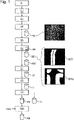
- the 8 Fig. 12 shows a fluorescence image of a rat stomach as an example of organ section.
- organ sections are, for example, the so-called mucous layer SC2 or the mucous membrane with parietal cells and interglandular contractile fibrils, also called tunica mucosa.
- Another organ layer is, for example, the ring and longitudinal muscle, also called tunica muscularis SC1.
- Another organ layer is, for example, the so-called displacement layer, also called submucosa SC3.
- Another organ layer, for example, is the muscularis mucosae SC4.
- Another organ layer for example, are the vessels SC5.
- ASMA anti-smooth muscle antibody pattern
- two specific organ layers are relevant for detecting the pattern: the tunica muscularis on the one hand and the tunica mucosa on the other.
- a presence of what is known as an ASMA pattern is evident insofar as there are respective, specific partial fluorescence patterns on the two previously mentioned organ layers, which together form the fluorescence pattern ASMA.
- ASMA fluorescence pattern
- a combination of a network or lattice-like pattern in the tunica muscularis organ layer and also a pattern of fine lines (interglandular contractile fibrils) on the tunica mucosa organ layer is used here. It is therefore necessary for these two aforementioned organ layers to be present in the fluorescence image to a sufficient degree or with a sufficient partial area in relation to the total area of the fluorescence image so that the presence of the ASMA pattern can be reliably detected using digital image processing.
- the inventors have thus recognized that with the principle of immunofluorescence microscopy based on organ sections in production, certain negative effects can occur which can counteract reliable detection of the presence of a fluorescence pattern by image processing.
- An organ section like from the 8 may not have a sufficient surface area of the two aforementioned organ layers. Production errors can result in at least one of the two layers or both layers only being present over a very small area in the fluorescence image. Detection of the fluorescence pattern using digital image processing and neural networks can then possibly lead to incorrect results, which should be avoided.
- the necessary organ material is not available in unlimited quantities.
- a larger organ section is first applied to a support surface and then the support surface is divided into partial support surfaces on glass, preferably by cutting, so that the slide can only be partially covered in certain areas of the organ section. Therefore, in the course of production, it may be possible that certain organ layers are only present to a small extent in the organ section.
- a further negative technical effect can occur:
- the fluorescence images are sometimes recorded using microscope optics of a specific optical magnification. This can lead to a fluorescence image that does not capture or display the entire object slide or the entire organ section. This can also result in a specific organ layer only being present to a small extent in the fluorescence image of the organ section.
- a method according to the invention for detecting a potential presence of a fluorescence pattern type on an organ section by means of immunofluorescence microscopy and by means of digital image processing is therefore proposed.
- the process has several steps. First, the organ section is provided on a slide. The organ section is then incubated with a liquid patient sample which potentially has primary antibodies. Furthermore, the organ section is incubated with secondary antibodies which are labeled with a fluorescent dye. A fluorescence image of the organ section is then recorded in a color channel which corresponds to the fluorescent dye. Furthermore, the fluorescence image is provided to a neural network.
- the method is characterized in that segmentation information is simultaneously determined by segmenting the fluorescence image by means of a neural network and that a confidence measure, which indicates an actual presence of the fluorescence pattern type, is also determined at the same time.
- At least one partial area of the fluorescence image which is relevant for a formation of the fluorescence pattern type, is determined on the basis of the previously determined segmentation information.
- a piece of validity information is determined, which indicates a degree of validity of the confidence measure, on the basis of the previously determined at least one partial area.
- the confidence measure of the actual presence of the fluorescence pattern type is output as a function of the validity information.
- the method according to the invention checks whether a specific organ layer is present to a sufficient degree as a partial area that is relevant for the formation of the fluorescence pattern type, and that the validity information is then determined on the basis of the previously determined partial area, the output of the Confidence measure are controlled or influenced accordingly.
- the confidence measure can be checked using the partial area.
- a specific partial area therefore corresponds to a specific organ layer.
- the partial area of the fluorescence image is therefore in particular a partial area which is assigned to a specific organ section or a specific organ layer on the basis of the segmentation information.
- the partial area is determined as a partial area which represents a specific organ layer, this partial area or this organ layer being determined on the basis of the segmentation information. It can therefore be ensured by checking the sub-area that the determined confidence level with regard to the presence of the fluorescence pattern type is also valid, since in the event that, for example, the sub-area or the organ layer is too small or too small, the Confidence measure can be detected as not valid.
- the confidence measure can preferably not be output.
- One neural network simultaneously determines the segmentation information related to the fluorescence image and the confidence level for the presence of the fluorescence pattern type.
- the neural network is designed in such a way that information about both the fluorescence pattern and at least one specific visible organ layer or its partial area can be included in the analysis by the neural network in determining the confidence level with regard to the presence of the fluorescence pattern type.
- the neural network is a pre-trained neural network which, during the training, has learned both confidence measures with regard to the presence of the fluorescence pattern type and segmentation information relating to a segmentation of the fluorescence image.
- the segmentation information represents, in particular, a plurality of partial segmentation information items, which each represent different organ layers of the organ section.
- image processing does not take place, which is known from the prior art:
- so-called masks in the form of image segments or as segmentation information can first be determined and then placed over the actual fluorescence image before a neural network then only those masked partial areas of the fluorescence image are analyzed, which were filtered out by the mask or the segmentation information, in order to determine a confidence measure.
- the segmentation information would first be finally determined, then applied to the fluorescence image as a mask and only partial image regions of the fluorescence image determined by means of masking would be included in the analysis or the determination of the confidence levels with regard to the presence of the fluorescence pattern.
- the fluorescence image is first transformed into the so-called feature space or characteristic space by transforming the fluorescence image by means of at least one convolutional operation, the resulting feature information then only being processed further after this transformation into the characteristic space. to determine both the segmentation information and the confidence measure based on this feature information.
- the segmentation information or segmentation masks are not placed over the fluorescence image, but rather the determination of the segmentation information and the determination of the confidence measure are mutually dependent in the processing of the neural network.
- the determination of the confidence measure can be advantageously influenced by the fact that the segmentation information, which is also determined at the same time influences the determination of the confidence measure and thus implicitly certain segmentation information or certain organ layers can be emphasized or given greater weight.
- a further advantage consists in particular in the fact that the training of the neural network does not take place in two separate steps, but that the training simultaneously brings about an optimization of the neural network with regard to the segmentation and the determination of the confidence measure.
- the method preferably has further steps: determining a plurality of sub-areas of the fluorescence image which are relevant for forming the fluorescence pattern type, based on the segmentation information, and determining validity information, which indicates a degree of validity of the confidence measure, based on the previously determined sub-areas.
- the method preferably has further steps: determining an area proportion of the at least one partial area in relation to the area of the fluorescence image and determining the validity information on the basis of the area proportion.
- the method preferably has further steps: determining the respective area proportions of the respective partial areas in relation to the area of the fluorescence image and determining the validity information on the basis of the area proportions.
- the method preferably has further steps: determining a plurality of sub-areas of the fluorescence image which are relevant for forming the fluorescence pattern type on the basis of the segmentation information, determining respective surface portions of the respective sub-surfaces in relation to the surface of the fluorescence image, determining the validity information on the basis of the surface portions and on Based on respective threshold values, outputting the confidence measure of the actual presence of the fluorescent pattern type in the event that the respective area proportions exceed a respective threshold value.
- the neural network is preferably designed in such a way that, based on the fluorescence image, it initially generates a first set of multiple feature information items in a feature space by means of at least one or multiple convolutional operations and then the segmentation information and the confidence measure are determined on the basis of the first set of feature information.
- the neural network is preferably designed in such a way that it first generates a first set of multiple pieces of feature information in a feature space using one or more convolutional operations based on the fluorescence image, then determines the segmentation information based on the first piece of feature information and then The confidence measure is determined on the basis of the first set of feature information and on the basis of the segmentation information.
- the neural network is preferably designed in such a way that it first generates a first set of multiple pieces of feature information in a feature space using one or more convolutional operations based on the fluorescence image, then determines the segmentation information based on the first piece of feature information, then Based on the segmentation information, a second set of multiple feature information is generated in a feature space by means of at least one convolutional operation and the confidence measure is then determined based on the first set of feature information and the second set of feature information.
- the method preferably has further steps: determining a plurality of sub-areas of the fluorescence image which are relevant for forming the fluorescence pattern type, on the basis of the segmentation information, and in the event that the fluorescence pattern type is determined to be actually present, determining a degree of brightness of one of the sub-areas in the Fluorescence image, which is potentially relevant for formation of the fluorescence pattern type, and estimation of a maximum degree of dilution of the patient sample at which incubation of the organ section with the patient sample still leads to the presence of one of the fluorescence pattern type.
- a device for detecting at least one potential presence of at least one type of fluorescence pattern on an organ section by means of immunofluorescence microscopy and by means of digital image processing having a holding device for a slide with an organ section, which is coated with a patient sample containing the autoantibodies, and also with secondary antibodies, which are each marked with a fluorescent dye, at least one image acquisition unit for acquiring a fluorescent image of the organ section in a color channel which corresponds to the fluorescent dye.
- the device also has at least one computing unit which is designed to provide the fluorescence image to a neural network, using the one neural network to simultaneously determine segmentation information by segmenting the fluorescence image and also to determine a confidence measure which indicates an actual presence of the fluorescence pattern type, to determine at least one partial area of the fluorescence image which is relevant for a formation of the fluorescence pattern type, on the basis of segmentation information, to determine validity information which indicates a degree of validity of the confidence measure (CM), based on the previously determined at least one partial area and to output the confidence measure of the actual presence of the fluorescence pattern type as a function of the validity information.
- CM degree of validity of the confidence measure
- a method for digital image processing comprising the steps: receiving a fluorescence image, which represents a staining of an organ section by a fluorescence dye, providing the fluorescence image to a neural network, simultaneously determining segmentation information by segmenting the fluorescence image and determining a confidence measure which indicates an actual presence of the fluorescence pattern type, by means of the one common neural network, determining at least one partial area of the fluorescence image which is relevant for a formation of the fluorescence pattern type on the basis of the segmentation information, determining validity information which indicates a degree of validity of the confidence measure on the basis the previously determined at least one partial area, outputting the confidence level of the actual presence of the fluorescence pattern type as a function of the validity information.
- a computer program product comprising instructions which, when the program is executed by a computer, cause the computer to carry out the method for digital image processing.
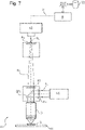
- FIG 10 shows a device V1, by means of which the method according to the invention can preferably be carried out.
- the device V1 can be referred to as a fluorescence microscope.
- the device V1 has a holder H for a substrate S or an object slide, which has been incubated in the manner described above.
- Excitation light AL from an excitation light source LQ is guided to the substrate S via an optical system O.
- Resulting fluorescence radiation FL is then retransmitted through the optics O and passes through the dichroic mirror SP1 and an optional optical filter F2.
- the fluorescence radiation FL preferably passes through an optical filter FG, which filters out a green channel.
- a camera K1 is preferably a monochrome camera, which then captures the fluorescence radiation FL in a green channel when an optical filter FG is present.
- the camera K1 is a color image camera, which manages without using the optical filter FG and uses a Bayer matrix to capture the fluorescence image in the corresponding color channel as a green channel.
- the camera K1 provides the image information BI or the fluorescence image ready to a processing unit R, which processes this image information BI.
- the computing unit R can preferably output or provide data ED such as a fluorescence image, confidence measures and/or validity information via a data interface DS1.
- the 1 shows steps of an embodiment of the proposed method.
- the organ section is provided on a slide.
- the organ section is incubated with a liquid patient sample which potentially has primary antibodies.
- the organ section is incubated with secondary antibodies which are labeled with a fluorescent dye.
- a fluorescence image of the organ section is recorded in a color channel, which corresponds to the fluorescent dye.
- fluorescence image FB which is also shown here, for example, as a data element FB.
- a fluorescence image is also exemplified in 8 as well as the 9h shown.
- the 8 illustrated for the fluorescence image FB the organ layer tunica muscularis or as a layer SC1, further the organ layer tunica mucosa as a layer SC2, further the submucosa layer as a layer SC3, further the layer muscularis mucosae as a layer SC4 and also the vascular layer as a layer SC5.
- a step S5 the fluorescence image is provided to a neural network.
- the neural network can be used, for example, as a network NN in a step S6.
- segmentation information SEG is simultaneously determined by segmenting the fluorescence image FB.
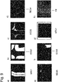
- This segmentation information SEG is shown here by way of example as a data element SEG and can have, for example, two pieces of segmentation information SEG1 and SEG2, which are also in Figure 9a and 9b are shown.
- the neural network simultaneously determines a confidence level KM with regard to an actual presence of a fluorescence pattern type to be detected.
- the neural network NN preferably not only determines a single confidence measure KM with regard to a single fluorescence pattern type or a single presence of a single fluorescence pattern type, but rather the neural network NN determines a plurality of confidence measures regarding several fluorescence pattern types.
- the data element includes KM from the 1 , shown respective confidence measures for respective presences of respective fluorescence pattern types.
- the data element KM from the 1 not just a single confidence measure, but for example thirteen confidence measures based on thirteen different fluorescence pattern types.
- Such a preferred embodiment with determination of respective confidence measures of respective actual presences of respective fluorescence pattern types is particularly advantageous because when the fluorescence image FB is analyzed by the neural network NN, the occurrence of different fluorescence pattern types is considered possible in the course of the solution and a more precise delimitation or determination of the specific type of fluorescence pattern whose presence is to be determined is taken into account and made possible by the neural network in the course of the analysis. In this case, therefore, it is not based on a purely positive or negative decision regarding the presence of the specific type of fluorescence pattern that one would like to detect as being present, but other possible patterns are also taken into account in the solution space.
- the neural network therefore preferably determines respective confidence measures with regard to the respective presences of respective fluorescence pattern types, a specific confidence measure of these confidence measures indicating the actual presence of the specific fluorescence pattern type. Later in the course of the method, the one specific confidence measure of the actual presence of the specific fluorescence pattern type is then preferably output as a function of the validity information.
- a partial area of the fluorescence image which is relevant for a formation of the fluorescence pattern type, is determined on the basis of the segmentation information SEG.
- the segmentation information SEG has, for example, seven different pieces of partial segmentation information SEG1 to SEG7, as shown in FIGS Figures 9a to 9g shown.
- a plurality of segmentation information relating to further layers can preferably be taken into account. For example, segmentation information relating to the presence of an organ layer of the gastric cavity, further segmentation information relating to so-called artefacts and, in turn, further segmenting information relating to other organ structures can be provided. For example, up to eleven different items of segmentation information can be provided.
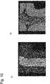
- the Figure 10a shows in an overlay in a highlighted manner patterns of the organ layer tunica muscularis based on the previously determined segmentation information SEG1 from FIG Figure 9a .
- the Figure 10b shows in an overlay pattern formation in a region of the organ layer tunica mucosae, the segmentation information SEG2 from the Figure 9b was used.
- a pattern for the presence of a pattern, in particular only those image areas or partial areas are considered or used which are relevant for the formation of the specific fluorescence pattern type. This can be at least a partial area of the fluorescence image which corresponds to a certain corresponding organ layer.
- a number of partial areas of the fluorescence image or a number of organ layers for example two organ layers, namely tunica muscularis and tunica mucosa, are used or viewed. These two layers are relevant for the formation of the fluorescence pattern type ASMA.
- the partial area TF1 is characterized by the white pixels of the segmentation information SEG1, for example Figure 9a given.
- the partial area TF2 is characterized by the white pixels of the segmentation information SEG2, for example Figure 9b given.
- a step S8 the validity information is then determined on the basis of the at least one partial area previously determined.
- the one or more sub-areas are represented as a data element TF.
- the validity information is therefore determined on the basis of the predetermined partial area TF as information VI, which is shown here as a data element VI.
- the respective area proportions of the respective partial areas or the respective organ layers are determined in relation to the area of the fluorescence image and the validity information is determined on the basis of the area proportions.
- This validity information VI can be a Boolean variable, for example, which assumes the value 1 in the event that the previously confidence measure KM is regarded as valid.
- step S9 that confidence measure KM which is relevant to the actual presence of the specific fluorescence pattern type is then output as a function of the validity information VI.
- the confidence measure KM can preferably not be output.
- an error message can then be output, which is not explicitly shown.
- the validity information VI is preferably also output in step S9.
- the previously determined confidence measure KM can, for example, be a vector of a plurality of scalar values, with the respective vector entries representing or indicating respective confidence measures based on respective fluorescence pattern types.
- step S9 preferably only that scalar value can be output as a confidence measure KM which indicates a confidence measure related to the fluorescence pattern to be detected, for example the ASMA pattern.
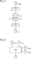
- the 2 shows an alternative step S71 to step S7, in which a plurality of partial areas TF1, TF2, which are relevant for a formation of the fluorescence pattern type, are determined on the basis of the segmentation information SEG.
- a plurality of partial areas TF1, TF2 which are relevant for a formation of the fluorescence pattern type, are determined on the basis of the segmentation information SEG.
- the pattern described above develops over two different organ layers, tunica mucosae and tunica muscularis. Both organ layers must be present to a sufficient degree or a sufficient surface area in the fluorescence image FB.
- step S81 as an alternative to step S8, in which the validity information VI is then determined on the basis of the plurality of partial areas TF1, TF2.
- the 3 shows a check of the partial areas TF1, TF2 based on respective threshold values SW1, SW2.
- Step S82 shown here is a step which is an alternative to step S81 from FIG 2 or step S8 from FIG 1 can be carried out.
- the validity information VI is then determined on the basis of the multiple partial areas TF1, TF2 and the respective threshold values SW1, SW2.
- the partial areas TF1 and TF2 have respective areas in relation to the area of the fluorescence image.
- step S82 from FIG 3 ie the confidence measure of the actual presence of the specific fluorescence pattern type is output in the event that the respective surface proportions of the respective surfaces TF1, TF2 exceed a respective threshold value SW1, SW2.
- the 4 shows preferred steps to discover different amounts of feature information. According to the 4 steps are shown which can preferably be carried out in the neural network NN.
- a step CO the fluorescence image FB is processed by means of one or more convolutional operations.
- a first set FI1 of a plurality of pieces of feature information is then generated in a feature space by means of the one or more convolutional operations on the basis of the fluorescence image FB.
- the segmentation information SEG and the confidence measure KM are then later determined on the basis of this quantity FI1 of feature information.
- a fluorescence image FB is first analyzed in a first network in order to determine segmentation information SEG, in order to then place the segmentation information SEG as a so-called image mask over the fluorescence image FB, and then subsequently a Analyzing the masked fluorescence image in a further network in order to determine the confidence measure KM is explicitly deviated from.
- the one neural network NN simultaneously determines the segmentation information SEG and the confidence measure KM.
- both segmentation information SEG and confidence measure KM can be determined simultaneously in a feature space and these are mutually dependent during a training phase of the neural network NN.
- the segmentation information SEG has an effect on the determination of the confidence measure KM while it is still in the feature space.
- the segmentation information SEG is then determined in a determination step BS1 on the basis of the first set of feature information FI1. Only then is the confidence measure KM subsequently determined on the basis of the first set of feature information FI1 and on the basis of the segmentation information SEG.
- the neural network NN thus simultaneously determines the segmentation information SEG and the confidence measure KM.
- the segmentation information SEG which was determined in the determination step BS1 on the basis of the feature information FI1, is preferably transformed again in the feature space into a second set of feature information FI2 in a determination step BS2. Based on the segmentation information SEG, a second set of multiple feature information items FI2 is therefore generated in a feature space by means of at least one convolutional operation. Only then is the confidence measure KM determined in the feature space in a determination step BS3 on the basis of the first set of feature information FI1 and the second set of feature information FI2.
- the segmentation information SEG is thus transformed in a determination step BS2 into a feature space or feature information FI2, which is then used in the feature space together with the first feature information FI1 to determine the confidence measure KM.
- the segmentation information SEG is therefore not applied directly to the fluorescence image FB, as is known from the prior art, but transformed in the feature space as feature information FI2 and there in the feature space the segmentation information SEG is then included in the determination of the confidence measure KM , especially together with the first set of feature information FI1.
- the entire fluorescence image FB is thus first transformed into the feature space as a piece of feature information FI1 and there is no back-transformation into the image space before the segmentation information SEG is determined.
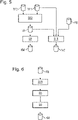
- Figure 12 shows preferred steps for estimating a maximum degree of dilution of the patient sample at which incubation of the organ section with the patient sample still results in the presence of the fluorescent pattern type.
- the patches TF1 and TF2 are in a step S82, as before with respect to the 3 describe, used to determine the validity information VI.
- the confidence measure KM can then be output as a function of the validity information VI.
- step S10 is in the figure 5 shown. If the validity information VI indicates that the fluorescence pattern type is determined to be actually present, then in step S10 a degree of brightness of a partial area in the fluorescence image can be determined, the partial area being potentially relevant for a formation of the fluorescence pattern type. For example, only a single organ layer can be used here in the event that two organ layers are relevant per se. This can be, for example, the organ layer tunica muscularis, to which in the Figure 9a a sub-area TF1 is shown.
- step S10 the maximum degree of dilution is then estimated as information VG on the basis of the partial area TF1 and the fluorescence image FB.
- the segmentation information of the partial area TF1 see FIG Figure 9a placed as a mask over the fluorescence image FB as segmentation information SEG1 and then the degree of brightness or degree of intensity in this partial area region is determined and the corresponding maximum degree of dilution is estimated on the basis of this degree of brightness.
- pixel statistics are preferably carried out on this relevant fluorescence image area of the organ layer.
- the 95% quantile of the brightness values from the partial image TF1 of the fluorescence image is determined.
- the brightness values can be quantized in the range from 0 to 255, for example. This entire quantization range of the brightness values from 0 to 255 can then be divided equidistantly into five partial value ranges. The first range then ranges from 0 to 51. The other ranges follow in corresponding equidistant steps, with the top fifth range ending at 255.
- a maximum degree of dilution of the patient sample can then be estimated at which incubation of the organ section with the patient sample still leads to the presence of one or the fluorescence pattern type.
- the information HI to be determined as the 95% quantile is then assigned to one of the partial value ranges accordingly.
- the determined partial value range or the index of the determined partial value range determines a step size, based on the existing dilution of the patient sample for the generation of the fluorescence image, in order to define a degree of dilution at which the patient sample level would still lead to a positive pattern or to a presence of the fluorescence pattern type .
- the degree of dilution VD of the sample from the incubation is therefore provided as additional information.
- the 6 shows preferred steps of a preferred embodiment of a proposed method for digital image processing.
- the fluorescence image FB is received in a step S1A.
- Step S1A is followed by steps S5 to S9 from FIG 1 on.
- a computer program product comprising instructions which, when the program is executed by a computer, cause the latter to carry out the method for digital image processing of the proposed form.
- the confidence measure KM can be checked again in a further step S9A. If the confidence measure KM has a value that exceeds a provided threshold value SWX, then the confidence measure KM is output. In this case, the confidence measure KM must therefore have a minimum certainty with regard to the presence of the specific fluorescence pattern type.
- the figure 12 shows an overview structure of a preferred embodiment of the neural network NN, which receives the fluorescence image FB.
- the fluorescence image FB is received and pre-processed in a processing block B1.
- a block DB follows, in which downsampling is carried out.
- the output of the block DB is then fed to a processing block VB1 and also to an upsampling block UB.
- a processing block VB1 is supplied to a further following processing block VB1 and also to an upsampling block UB.
- the output of the upsampling blocks UB and the output of the last processing block VB1 are concatenated in a concatenation block CONC.
- the output of the concatenation block CONC is then fed to a processing block VB1 and also to a processing block VB2.
- the output of the processing block VB1 is then fed to a block SOB for outputting a segmentation result SEG.
- the segmentation result or the segmentation information SEG is then output in block SOB.
- This segmentation information SEG is also supplied to a further processing block VB2.
- the processing block VB2 uses the output variable INF of the concatenation block CONC and the segmentation information SEG to determine the confidence measure KM, which is output in a block COB.
- An upsampling block UB initially has a block CB in which a two-dimensional folding or a “2-dimensional convolution” is carried out.
- a block LB follows with a LeakyReLU function.
- a so-called upsampling block UPB also follows.
- a processing block VB1 initially has a block IB, in which an input variable is received and then fed to different blocks BAC, ADB.
- BAC a sequence of the operation Batchnorm, Activation, Convolution takes place.
- block ADB the several input variables provided for the block ADB are added element by element, here from the block IB and a block BAC.
- a convolutional batch norm activation block CBNB first has a block CB, then a batch norm block BNB and then a block LB.
- a batch standard activation convolution block BAC first has a block BNB, then a block LB and then a block CB.
- a processing block VB2 has an input block IB1, which receives the segmentation information SEG.
- Another parallel input block IB2 accepts the information INF, which is also in the figure 12 is shown.
- the information INF is the information which the concatenation block CONC generates there and transfers to the processing block VB2.
- the segmentation information SEG is then transferred to a block CBNB after the block IB1.
- the information generated there is transferred to a Max Pooling 2D Block MB on the left and to a Max Pooling 2D Block MB on the right.
- the size determined by the block MB is then transferred to a concatenation block CONC in the processing line on the left-hand side.
- a sequence of a block MB, a block CONC and a block CBNB is carried out in the right-hand strand before the correspondingly ascertained information is also transferred to the concatenation block CONC.
- Two blocks of type CBNB follow.
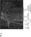
- the performance data were determined using 78 patient samples. Each sample was titrated in 3 titration steps and then one substrate or one organ section was incubated for each titration step. The incubated substrates were recorded in the form of fluorescence images using the EURO-Pattern Microscope 1.5 microscope. There were 3 results for each of the 3 titration levels for each sample. If the proposed method showed the presence of at least one of the 3 fluorescence images of the specific sample Fluorescence pattern type detected as positive, it was decided that the fluorescence pattern type was present in principle.
- the table TAB from the figure 11 shows that of 21 actually positive samples, the proposed method recognized 19 samples as positive and 2 samples were incorrectly recognized as negative.
- the table from the figure 11 also shows that of 57 samples that were actually negative, the proposed method recognized 55 samples as negative and 2 samples were falsely recognized as positive. This results in an analytical sensitivity of 0.90. Furthermore, this results in an analytical specificity of 0.96.
- embodiments of the invention can implement the computing unit R or the data network device in hardware and/or in software.
- An arithmetic unit R mentioned here can be implemented as at least one arithmetic unit or by a plurality of arithmetic units in the network.
- the implementation may be performed using a digital storage medium such as a floppy disk, a DVD, a Blu-ray disk, a CD, a ROM, a PROM, an EPROM, an EEPROM or a FLASH memory, a hard disk or other magnetic or optical memory, on which electronically readable control signals are stored, which can interact or interact with a programmable hardware component in such a way that the respective method is carried out.
- CPU computer processor
- ASIC application-specific integrated circuit
- IC integrated circuit
- SOC system on chip
- FPGA Field Programmable Gate Array
- the digital storage medium can therefore be machine or computer readable.
- some embodiments include a data carrier that has electronically readable control signals that are capable of interacting with a programmable computer system or a programmable hardware component in such a way that one of the methods described herein is carried out.
- embodiments or parts of the embodiments of the present invention can be implemented as a program, firmware, computer program or computer program product with a program code or as data, the program code or the data being operative to perform one of the methods or a part of a method , if the program runs on a processor or a programmable hardware component.
Landscapes
- Engineering & Computer Science (AREA)
- Health & Medical Sciences (AREA)
- Physics & Mathematics (AREA)
- Life Sciences & Earth Sciences (AREA)
- General Physics & Mathematics (AREA)
- Theoretical Computer Science (AREA)
- General Health & Medical Sciences (AREA)
- Biomedical Technology (AREA)
- Molecular Biology (AREA)
- Immunology (AREA)
- Chemical & Material Sciences (AREA)
- Computer Vision & Pattern Recognition (AREA)
- Hematology (AREA)
- Urology & Nephrology (AREA)
- Pathology (AREA)
- Analytical Chemistry (AREA)
- Biochemistry (AREA)
- Data Mining & Analysis (AREA)
- Nuclear Medicine, Radiotherapy & Molecular Imaging (AREA)
- Artificial Intelligence (AREA)
- General Engineering & Computer Science (AREA)
- Evolutionary Computation (AREA)
- Food Science & Technology (AREA)
- Microbiology (AREA)
- Medicinal Chemistry (AREA)
- Cell Biology (AREA)
- Biotechnology (AREA)
- Software Systems (AREA)
- Multimedia (AREA)
- Biophysics (AREA)
- Computational Linguistics (AREA)
- Computing Systems (AREA)
- Mathematical Physics (AREA)
- Medical Informatics (AREA)
- Radiology & Medical Imaging (AREA)
- Quality & Reliability (AREA)
- Geometry (AREA)
- Bioinformatics & Computational Biology (AREA)
- Bioinformatics & Cheminformatics (AREA)
- Rehabilitation Therapy (AREA)
Abstract
Description
- Die Erfindung betrifft ein Verfahren sowie eine Vorrichtung zum Detektieren einer potentiellen Präsenz eines Fluoreszenzmustertyps auf einem Organschnitt mittels Immunfluoreszenzmikroskopie und mittels digitaler Bildverarbeitung.
- Eine Immunfluoreszenzmikroskopie bzw. indirekte Immunfluoreszenzmikroskopie ist ein invitro-Test für eine Bestimmung einer Präsenz humaner Antikörper gegen bestimmte Antigene, um eine diagnostische Fragestellung beantworten bzw. einschätzen zu können. Derartige Antigene sind beispielsweise in bestimmten Bereichen von Organschnitten wie eines Rattenmagens vorhanden. Als Substrat dient also ein Organschnitt, welcher mit einer Patientenprobe in Form von Blut oder verdünntem Blut oder aber Blutserum oder verdünntem Blutserum inkubiert wird. Die Patientenprobe weist also potentiell bestimmte primäre Antikörper auf, welche Ausdruck eines Vorhandenseins einer Erkrankung des Patienten sein können. Solche primären bzw. spezifischen Antikörper können dann an Antigene des Substrats bzw. des Organschnittes binden. Derartig gebundene primäre Antikörper können dann dadurch markiert werden, dass in einem weiteren Inkubationsschritt sogenannte sekundäre Antikörper, vorzugsweise Anti-Human-Antikörper, an die gebundenen primären Antikörper anbinden und später dadurch sichtbar gemacht werden können, dass die sekundären Antikörper mit einem Fluoreszenzfarbstoff markiert sind. Ein solcher Fluoreszenzfarbstoff ist vorzugsweise ein grüner Fluoreszenzfarbstoff, insbesondere der Fluoreszenzfarbstoff FITC. Eine solche Bindung eines primären Antikörpers gemeinsam mit einem fluoreszenzmarkierten sekundären Antikörper kann dann später dadurch sichtbar gemacht werden, dass der Organschnitt mit Anregungslicht einer bestimmten Wellenlänge bestrahlt wird und somit die gebundenen Fluoreszenzfarbstoffe zur Emission von Fluoreszenzstrahlung angeregt werden.
- Abhängig von der diagnostischen Fragestellung kann auf eine Präsenz eines oder ganz bestimmter Fluoreszenzmustertypen auf bestimmten Organschnitten bzw. ganz bestimmten Teilbereichen bzw. Teilflächen der Organschnitte abgestellt werden. Es ergibt sich also die Aufgabe, mittels digitaler Bildverarbeitung im Zuge einer Immunfluoreszenzmikroskopie bei einem in der vorgeschriebenen Weise inkubierten Organschnitt mittels digitaler Bildverarbeitung einen oder mehrere Fluoreszenzmustertypen in einem Fluoreszenzbild einer Immunfluoreszenzmikroskopie zu Detektieren.
- Die
Fig. 8 zeigt ein Fluoreszenzbild eines Magens einer Ratte als ein Beispiel eines Organschnittes. Ein solcher Organschnitt weist unterschiedliche Organschichten auf. Organschichten sind hierbei beispielsweise die sogenannte Schleimschicht SC2 bzw. die Schleimhaut mit Parietalzellen und interglandulären kontraktilen Fibrillen, auch Tunica mucosa genannt.
Eine weitere Organschicht ist beispielsweise der Ring- und Längsmuskel, auch Tunica muscularis SC1 genannt. Eine weitere Organschicht ist beispielsweise die sogenannte Verschiebeschicht, auch Submucosa SC3 genannt. Eine wiederum andere Organschicht ist beispielsweise die Muscularis mucosae SC4. Eine wiederum andere Organschicht sind beispielsweise die Gefäße SC5. - Für ein beispielhaftes Anti-Smooth-Muscle-Antibody-Muster (ASMA) sind für eine Detektion des Musters zwei bestimmte Organschichten relevant: zum einen Tunica muscularis und zum anderen Tunica mucosa. Mittels Detektion einer Präsenz des ASMA-Musters kann dann möglicherweise anschließend durch einen Arzt oder Experten auf Vorliegen einer Hepatitis-Erkrankung geschlossen werden.
- Eine Präsenz eines sogenannten ASMA-Musters zeigt sich insofern, dass es auf den zwei zuvor genannten Organschichten zu jeweiligen, bestimmten Teil-Fluoreszenzmustern kommt, welche gemeinsam das Fluoreszenzmuster ASMA bilden. Insbesondere wird hier auf eine Kombination aus einem netz- oder gitterartigen Muster in der Organschicht Tunica muscularis sowie auch ein Muster feiner Linien (interglanduläre kontraktile Fibrillen) auf der Tunica-mucosa-Organschicht abgestellt. Es ist daher notwendig, dass in dem Fluoreszenzbild diese beiden zuvor genannten Organschichten zu einem ausreichenden Grad bzw. mit einer ausreichenden Teilfläche bezogen auf die Gesamtfläche des Fluoreszenzbildes vorhanden sind, damit eine Präsenz des ASMA-Musters mittels einer digitalen Bildverarbeitung sicher detektiert werden kann.
- Die Erfinder haben also erkannt, dass bei dem Prinzip der Immunfluoreszenzmikroskopie basierend auf Organschnitten in der Produktion bestimmte negative Auswirkungen vorkommen können, welche einer sicheren Detektion einer Präsenz eines Fluoreszenzmusters durch Bildverarbeitung entgegenwirken können. Ein Organschnitt wie aus der
Fig. 8 weist möglicherweise die beiden zuvor genannten Organschichten jeweils nicht zu einem hinreichenden Flächenanteil auf. Durch Produktionsfehler kann es dazu kommen, dass zumindest eine der beiden Schichten oder aber beide Schichten jeweils nur zu einem sehr geringen Flächenanteil in dem Fluoreszenzbild vorhanden sind. Eine Detektion des Fluoreszenzmusters mittels digitaler Bildverarbeitung und neuronaler Netze kann dann möglicherweise zu Fehlergebnissen führen, welches vermieden werden sollte. - Im Produktionsprozess steht notwendiges Organmaterial nicht unbegrenzt zur Verfügung. Ein größerer Organschnitt wird zunächst auf eine Trägerfläche aufgebracht und dann die Trägerfläche in Teilträgerflächen auf Glas zerteilt, vorzugsweise mittels Schneiden, so dass es gerade in gewissen Bereichen des Organschnittes nur zu einer teilweisen Abdeckung des Objektträgers kommen kann. Daher kann im Zuge der Produktion es möglich sein, dass bestimmte Organschichten nur zu einem geringen Anteil in dem Organschnitt vorhanden sind.
- Alternativ oder zusätzlich kann ein weiterer negativer technischer Effekt auftreten: Zur hinreichenden Darstellung bzw. Erkennbarkeit von Mustern in einem Fluoreszenzbild werden mitunter die Fluoreszenzbilder unter Verwendung von Mikroskopoptiken bestimmter optischer Vergrößerung erfasst. Dies kann zu einem Fluoreszenzbild führen, welches nicht den gesamten Objektträger und auch nicht den gesamten Organschnitt erfasst bzw. darstellt. Auch hierdurch kann es dazu kommen, dass eine bestimmte Organschicht nur zu einem geringen Anteil in dem Fluoreszenzbild des Organschnittes vorhanden ist.
- Vorgeschlagen wird daher ein erfindungsgemäßes Verfahren zum Detektieren einer potentiellen Präsenz eines Fluoreszenzmustertyps auf einem Organschnitt mittels Immunfluoreszenzmikroskopie und mittels digitaler Bildverarbeitung.
- Das Verfahren weist verschiedene Schritte auf. Zunächst erfolgt ein Bereitstellen des Organschnittes auf einem Objektträger. Anschließend erfolgt ein Inkubieren des Organschnittes mit einer flüssigen Patientenprobe, welche potentiell primäre Antikörper aufweist. Ferner erfolgt ein Inkubieren des Organschnittes mit sekundären Antikörpern, welche mit einem Fluoreszenzfarbstoff markiert sind. Es erfolgt dann ein Erfassen eines Fluoreszenzbildes des Organschnittes in einem Farbkanal, welcher zu dem Fluoreszenzfarbstoff korrespondiert. Ferner erfolgt ein Bereitstellen des Fluoreszenzbildes an ein neuronales Netz.
- Das Verfahren zeichnet sich dadurch aus, dass mittels eines neuronalen Netzes gleichzeitig eine Segmentierungsinformation durch Segmentieren des Fluoreszenzbildes bestimmt wird und dass ferner eben auch gleichzeitig ein Konfidenzmaß, welches eine tatsächliche Präsenz des Fluoreszenzmustertyps indiziert, bestimmt wird.
- Ferner erfolgt ein Bestimmen wenigstens einer Teilfläche des Fluoreszenzbildes, welche für eine Ausbildung des Fluoreszenzmustertyps relevant ist, auf Basis der zuvor bestimmten Segmentierungsinformation.
- Ferner erfolgt ein Bestimmen einer Validitätsinformation, welche einen Grad einer Validität des Konfidenzmaßes indiziert, auf Basis der zuvor bestimmten wenigstens einen Teilfläche.
- Ferner erfolgt schließlich ein Ausgeben des Konfidenzmaßes der tatsächlichen Präsenz des Fluoreszenzmustertyps in Abhängigkeit der Validitätsinformation.
- Zur Verdeutlichung eines oder mehrerer möglicher Vorteile erfolgt nun im Weiteren eine genauere Darlegung verschiedener Aspekte des erfindungsgemäßen Verfahrens.
- Wie bereits zuvor ausgeführt, können unterschiedliche Probleme bei der Anfertigung von Organschnitten auf Objektträgern auftreten, so dass für ein zu detektierendes Muster bzw. Fluoreszenzmuster relevante Organschichten nicht zu einem hinreichenden Abdeckungsgrad bzw. hinreichender Teilflächen vorhanden sind. Dadurch, dass das erfindungsgemäße Verfahren überprüft, ob eine bestimmte Organschicht als eine Teilfläche, welche für eine Ausbildung des Fluoreszenzmustertyps relevant ist, zu einem hinreichenden Grad präsent ist, und dass dann die Validitätsinformation auf Basis der zuvor bestimmten Teilfläche ermittelt wird, kann das Ausgeben des Konfidenzmaßes entsprechend gesteuert bzw. beeinflusst werden. Mit anderen Worten: Das Konfidenzmaß kann anhand der Teilfläche überprüft werden. Eine bestimmte Teilfläche korrespondiert also zu einer bestimmten Organschicht. Die Teilfläche des Fluoreszenzbildes ist also insbesondere eine Teilfläche, welche einem bestimmten Organabschnitt bzw. einer bestimmten Organschicht auf Basis der Segmentierungsinformation zugeordnet wird. Mit anderen Worten: Die Teilfläche wird als eine Teilfläche bestimmt, welche eine bestimmte Organschicht repräsentiert, wobei diese Teilfläche bzw. diese Organschicht auf Basis der Segmentierungsinformation bestimmt wird.
Es kann also somit durch Überprüfung der Teilfläche gewährleistet werden, dass das ermittelte Konfidenzmaß bezüglich der Präsenz des Fluoreszenzmustertypen auch valide ist, da in dem Fall, dass beispielsweise die Teilfläche bzw. die Organschicht eine zu geringe Größe bzw. ein zu geringes Maß aufweist, das Konfidenzmaß als nicht valide detektiert werden kann. - Es kann beispielsweise in dem Fall, dass die Teilfläche zu klein ist, das Konfidenzmaß vorzugsweise nicht ausgegeben werden.
- Ferner ist das vorgeschlagene Verfahren insbesondere aus einem weiteren Grund vorteilhaft. Das eine neuronale Netz bestimmt gleichzeitig die Segmentierungsinformation bezogen auf das Fluoreszenzbild sowie das Konfidenzmaß für die Präsenz des Fluoreszenzmustertypen. Das neuronale Netz ist also so konzipiert, dass gleichzeitig sowohl Informationen über das Fluoreszenzmuster als auch wenigstens einer bestimmten sichtbaren Organschicht bzw. deren Teilfläche in die Analyse durch das neuronale Netz in die Bestimmung des Konfidenzmaßes bezüglich der Präsenz des Fluoreszenzmustertyps einfließen können. Mit anderen Worten: Das neuronale Netz ist ein vortrainiertes neuronales Netz, welches während des Trainings sowohl Konfidenzmaße hinsichtlich eines Vorliegens bzw. einer Präsenz des Fluoreszenzmustertypen als auch eine Segmentierungsinformation bezogen auf ein Segmentieren des Fluoreszenzbildes erlernt hat. Hierbei repräsentiert die Segmentierungsinformation insbesondere mehrere Teilsegmentierungsinformationen, welche jeweils für sich jeweilige unterschiedliche Organschichten des Organschnittes repräsentieren.
- Es erfolgt eben erfindungsgemäß gerade nicht eine Bildverarbeitung, welche aus dem Stand der Technik bekannt ist: Hierbei können im Stand der Technik zunächst sogenannte Masken in Form von Bildsegmenten bzw. als Segmentierungsinformationen ermittelt werden und dann über das eigentliche Fluoreszenzbild gelegt werden, bevor ein neuronales Netz dann nur noch jene maskierten Teilbereiche des Fluoreszenzbildes analysiert, welche durch die Maske bzw. die Segmentierungsinformation herausgefiltert wurden, um ein Konfidenzmaß zu bestimmen. Hierbei würde also zunächst die Segmentierungsinformation final ermittelt werden, dann anschließend als Maske auf das Fluoreszenzbild angewendet werden und nur noch mittels Maskierung ermittelter Teilbildbereiche des Fluoreszenzbildes Eingang in die Analyse bzw. das Bestimmen der Konfidenzmaße hinsichtlich der Präsenz des Fluoreszenzmusters finden.
- Ein solches Verfahren nach dem Stand der Technik wird gerade erfindungsgemäß nicht verfolgt, da eben gleichzeitig die Segmentierungsinformation als auch das Konfidenzmaß durch das neuronale Netz ermittelt werden. Insbesondere erfolgt vorzugsweise in dem erfindungsgemäßen Verfahren zunächst eine Transformation des Fluoreszenzbildes in den sogenannten Feature-raum bzw. Merkmalsraum durch Transformation des Fluoreszenzbildes mittels wenigstens einer Convolutional-Operation, wobei dann erst nach dieser Transformation in den Merkmalsraum die sich ergebenden Feature-Informationen weiterverarbeitet werden, um auf Basis dieser Feature-Informationen sowohl die Segmentierungsinformation als auch das Konfidenzmaß zu ermitteln. In diesem vorzugsweise ausgestalteten Verfahren gemäß einer bevorzugten Ausführungsform wird dann also eben nicht die Segmentierungsinformation bzw. Segmentierungsmasken über das Fluoreszenzbild gelegt, sondern in der Verarbeitung des neuronalen Netzes bedingen sich die Bestimmung der Segmentierungsinformation und die Bestimmung des Konfidenzmaßes gegenseitig. Hierdurch kann vorzugsweise gerade in einer Trainingsphase des neuronalen Netzes die Bestimmung des Konfidenzmaßes dadurch vorteilhaft beeinflusst werden, dass die ebenfalls gleichzeitig bestimmte Segmentierungsinformation die Bestimmung des Konfidenzmaßes beeinflusst und somit implizit bestimmte Segmentierungsinformation bzw. bestimmte Organschichten hervorgehoben bzw. stärker Eingang finden können. Ein weiterer Vorteil besteht insbesondere darin, dass das Training des neuronalen Netzes nicht in zwei separaten Schritten stattfindet, sondern dass das Training gleichzeitig eine Optimierung des neuronalen Netzes hinsichtlich der Segmentierung als auch der Bestimmung des Konfidenzmaßes herbeiführt.
- Vorteilhafte Ausführungsformen der Erfindung sind Gegenstand der abhängigen Ansprüche und werden in der folgenden Beschreibung unter teilweiser Bezugnahme auf die Figuren näher erläutert.
- Vorzugsweise weist das Verfahren weitere Schritte auf: Bestimmen mehrerer Teilflächen des Fluoreszenzbildes, welche für eine Ausbildung des Fluoreszenzmustertyps relevant sind, auf Basis der Segmentierungsinformation, sowie Bestimmen einer Validitätsinformation, welche einen Grad einer Validität des Konfidenzmaßes indiziert, auf Basis der zuvor bestimmten Teilflächen.
- Vorzugsweise weist das Verfahren weitere Schritte auf: Bestimmen eines Flächenanteils der wenigstens einen Teilfläche bezogen auf die Fläche des Fluoreszenzbildes sowie Bestimmen der Validitätsinformation auf Basis des Flächenanteils.
- Vorzugsweise weist das Verfahren weitere Schritte auf: Bestimmen jeweiliger Flächenanteile der jeweiligen Teilflächen bezogen auf die Fläche des Fluoreszenzbildes sowie Bestimmen der Validitätsinformation auf Basis der Flächenanteile.
- Vorzugsweise weist das Verfahren weitere Schritte auf: Bestimmen mehrerer Teilflächen des Fluoreszenzbildes, welche für eine Ausbildung des Fluoreszenzmustertyps relevant sind, auf Basis der Segmentierungsinformation, Bestimmen jeweiliger Flächenanteile der jeweiligen Teilflächen bezogen auf die Fläche des Fluoreszenzbildes, Bestimmen der Validitätsinformation auf Basis der Flächenanteile und auf Basis jeweiliger Schwellenwerte, Ausgeben des Konfidenzmaßes der tatsächlichen Präsenz des Fluoreszenzmustertyps in dem Fall, dass die jeweiligen Flächenanteile einen jeweiligen Schwellenwert überschreiten.
- Vorzugsweise ist das neuronale Netz so ausgebildet, dass es zunächst auf Basis des Fluoreszenzbildes eine erste Menge mehrerer Feature-Informationen in einem Merkmalsraum mittels wenigstens einer oder mehrerer Convolutional-Operationen generiert und anschließend auf Basis der ersten Menge an Feature-Informationen die Segmentierungsinformation und das Konfidenzmaß bestimmt.
- Vorzugsweise ist das neuronale Netz so ausgebildet, dass es zunächst auf Basis des Fluoreszenzbildes eine erste Menge mehrerer Feature-Informationen in einem Merkmalsraum mittels einer oder mehrerer Convolutional-Operationen generiert, anschließend auf Basis der ersten Menge an Feature-Informationen die Segmentierungsinformation bestimmt und anschließend auf Basis der ersten Menge an Feature-Informationen und auf Basis der Segmentierungsinformation das Konfidenzmaß bestimmt.
- Vorzugsweise ist das neuronale Netz so ausgebildet, dass es zunächst auf Basis des Fluoreszenzbildes eine erste Menge mehrerer Feature-Informationen in einem Merkmalsraum mittels einer oder mehrerer Convolutional-Operationen generiert, anschließend auf Basis der ersten Menge an Feature-Informationen die Segmentierungsinformation bestimmt, anschließend auf Basis der Segmentierungsinformation eine zweite Menge mehrerer Feature-Informationen in einem Merkmalsraum mittels wenigstens einer Convolutional-Operation generiert und anschließend auf Basis der ersten Menge an Feature-Informationen und der zweiten Menge an Feature-Informationen das Konfidenzmaß bestimmt.
- Vorzugsweise weist das Verfahren weitere Schritte auf: Bestimmen mehrerer Teilflächen des Fluoreszenzbildes, welche für eine Ausbildung des Fluoreszenzmustertyps relevant sind, auf Basis der Segmentierungsinformation, und in dem Fall, dass der Fluoreszenzmustertyp als tatsächlich präsent bestimmt wird, Bestimmen eines Helligkeitsgrades einer der Teilfläche in dem Fluoreszenzbild, welche für eine Ausbildung des Fluoreszenzmustertyps potentiell relevant ist, sowie Abschätzen eines maximalen Verdünnungsgrades der Patientenprobe, bei welchem eine Inkubation des Organschnittes mit der Patientenprobe noch zu einer Präsenz eines des Fluoreszenzmustertyps führt.
- Vorgeschlagen wird ferner eine Vorrichtung zum Detektieren wenigstens einer potentiellen Präsenz wenigstens eines Fluoreszenzmustertyps auf einem Organschnitt mittels Immunfluoreszenzmikroskopie und mittels digitaler Bildverarbeitung, aufweisend eine Haltevorrichtung für einen Objektträger mit einem Organschnitt, welcher mit einer Patientenprobe, aufweisend die Autoantikörper, sowie ferner mit sekundären Antikörpern, welche jeweils mit einem Fluoreszenzfarbstoff markiert sind, inkubiert wurde, wenigstens eine Bilderfassungseinheit zum Erfassen eines Fluoreszenzbildes des Organschnittes in einem Farbkanal, welcher zu dem Fluoreszenzfarbstoff korrespondiert. Die Vorrichtung weist ferner wenigstens eine Recheneinheit auf, welche ausgebildet ist, das Fluoreszenzbild an ein neuronales Netz bereitzustellen, mittels des einen neuronalen Netzes gleichzeitig eine Segmentierungsinformation durch Segmentieren des Fluoreszenzbildes zu bestimmen und ferner ein Konfidenzmaß, welches eine tatsächliche Präsenz des Fluoreszenzmustertyps indiziert, zu bestimmen, wenigstens eine Teilfläche des Fluoreszenzbildes zu bestimmen, welche für eine Ausbildung des Fluoreszenzmustertyps relevant ist, auf Basis der Segmentierungsinformation, eine Validitätsinformation zu bestimmen, welche einen Grad einer Validität des Konfidenzmaßes (KM) indiziert, auf Basis der zuvor bestimmten wenigstens einen Teilfläche sowie das Konfidenzmaß der tatsächlichen Präsenz des Fluoreszenzmustertypes in Abhängigkeit der Validitätsinformation auszugeben.
- Vorgeschlagen wird ferner ein Verfahren zur digitalen Bildverarbeitung, aufweisend die Schritte: Entgegennehmen eines Fluoreszenzbildes, welches eine Färbung eines Organschnittes, durch einen Fluoreszenzfarbstoff repräsentiert, Bereitstellen des Fluoreszenzbildes an ein neuronales Netz, gleichzeitiges Bestimmen einer Segmentierungsinformation durch Segmentieren des Fluoreszenzbildes und Bestimmen eines Konfidenzmaßes, welches eine tatsächliche Präsenz des Fluoreszenzmustertyps indiziert, mittels des einen gemeinsamen neuronalen Netzes, Bestimmen wenigstens einer Teilfläche des Fluoreszenzbildes, welche für eine Ausbildung des Fluoreszenzmustertyps relevant ist, auf Basis der Segmentierungsinformation, Bestimmen einer Validitätsinformation, welche einen Grad einer Validität des Konfidenzmaßes indiziert, auf Basis der zuvor bestimmten wenigstens einen Teilfläche, Ausgeben des Konfidenzmaßes der tatsächlichen Präsenz des Fluoreszenzmustertypes in Abhängigkeit der Validitätsinformation.
- Vorgeschlagen wird ferner ein Computerprogrammprodukt, umfassend Befehle, die bei der Ausführung des Programms durch einen Computer diesen veranlassen, das Verfahren zur digitalen Bildverarbeitung durchzuführen.
- Im Folgenden wird die Erfindung anhand spezieller Ausführungsformen ohne Beschränkung des allgemeinen Erfindungsgedankens anhand der Figuren näher erläutert. Dabei zeigen:
-
Fig. 1 eine Ausführungsform des erfindungsgemäßen Verfahrens, -
Fig. 2 bevorzugte Schritte zum Bestimmen jeweiliger Flächenanteile, -
Fig. 3 eine Überprüfung jeweiliger Teilflächen hinsichtlich jeweiliger Schwellenwerte, -
Fig. 4 eine Ausführungsform des erfindungsgemäßen Verfahrens mit Bestimmungsschritten zur Generierung unterschiedlicher Mengen an Feature-Informationen, -
Fig. 5 bevorzugte Schritte zur Abschätzung eines maximalen Verdünnungsgrades einer Patientenprobe, bei welchem eine Inkubation des Organschnittes mit der Patientenprobe noch zu einer Präsenz des Fluoreszenzmustertyps führt, -
Fig. 6 bevorzugte Schritte eines vorgeschlagenen Verfahrens zur digitalen Bildverarbeitung, -
Fig. 7 eine Ausführungsform einer vorgeschlagenen Vorrichtung, -
Fig. 8 einen beispielhaften Organschnitt mit unterschiedlichen Organschichten, -
Fig. 9 ein Fluoreszenzbild wie ausFig. 8 zusammen mit Segmentierungsinformation, -
Fig. 10 unterschiedliche hervorgehobene Organschichten, -
Fig. 11 Experimentalergebnisse, -
Figur 12 eine Übersichtsstruktur einer Ausführungsform eines neuronalen Netzes sowie -
Figur 13 eine detaillierte Darstellung einzelner Verarbeitungsblöcke des neuronalen Netzes. -
Figur 10 zeigt eine Vorrichtung V1, mittels welcher das erfindungsgemäße Verfahren vorzugsweise durchgeführt werden kann. Die Vorrichtung V1 kann als ein Fluoreszenzmikroskop bezeichnet werden. Die Vorrichtung V1 weist eine Halterung H für ein Substrat S bzw. einen Objektträger auf, welches bzw. welcher in der zuvor beschriebenen Weise inkubiert wurde. Über eine Optik O wird Anregungslicht AL einer Anregungslichtquelle LQ hin zu dem Substrat S geleitet. Sich ergebende Fluoreszenzstrahlung FL wird dann durch die Optik O zurücktransmittiert und passiert den dichroitischen Spiegel SP1 und einen optionalen optischen Filter F2. Vorzugsweise passiert die Fluoreszenzstrahlung FL einen optischen Filter FG, welcher einen Grünkanal herausfiltert. Eine Kamera K1 ist vorzugsweise eine Monochromkamera, welche dann bei Vorhandensein eines optischen Filters FG die Fluoreszenzstrahlung FL in einem Grünkanal erfasst. Gemäß einer alternativen Ausführungsform ist die Kamera K1 eine Farbbildkamera, welche ohne Verwendung des optischen Filters FG auskommt und mittels einer Bayer-Matrix das Fluoreszenzbild in dem entsprechenden Farbkanal als einen Grünkanal erfasst. Die Kamera K1 stellt die Bildinformation BI bzw. das Fluoreszenzbild an eine Recheneinheit R bereit, welche diese Bildinformation BI verarbeitet. Vorzugsweise kann die Recheneinheit R über eine Datenschnittstelle DS1 Daten ED wie beispielsweise ein Fluoreszenzbild, Konfidenzmaße und/oder eine Validitätsinformation ausgeben bzw. bereitstellen. - Die
Fig. 1 zeigt Schritte einer Ausführungsform des vorgeschlagenen Verfahrens. In einem Schritt S1 wird der Organschnitt auf einem Objektträger bereitgestellt. In einem Schritt S2 erfolgt ein Inkubieren des Organschnittes mit einer flüssigen Patientenprobe, welche potentiell primäre Antikörper aufweist. In einem Schritt S3 erfolgt ein Inkubieren des Organschnittes mit sekundären Antikörpern, welche mit einem Fluoreszenzfarbstoff markiert sind. - In einem Schritt S4 erfolgt ein Erfassen eines Fluoreszenzbildes des Organschnittes in einem Farbkanal, welcher zu dem Fluoreszenzfarbstoff korrespondiert.
- Es ergibt sich dann das Fluoreszenzbild FB, welches hier beispielsweise auch als ein Datenelement FB dargestellt ist. Ein solches Fluoreszenzbild ist auch beispielhaft in der
Fig. 8 sowie derFig. 9h dargestellt. - Die
Fig. 8 illustriert für das Fluoreszenzbild FB die Organschicht Tunica muscularis bzw. als eine Schicht SC1, ferner die Organschicht Tunica mucosa als eine Schicht SC2, ferner die Schicht Submucosa als eine Schicht SC3, ferner die Schicht Muscularis mucosae als eine Schicht SC4 und ferner die Gefäß-Schicht als eine Schicht SC5. - Gemäß der
Figur 1 erfolgt in einem Schritt S5 das Bereitstellen des Fluoreszenzbildes an ein neuronales Netz. - Das neuronale Netz kann beispielsweise als ein Netz NN in einem Schritt S6 verwendet werden. In dem Schritt S6 erfolgt gleichzeitig ein Bestimmen einer Segmentierungsinformation SEG durch Segmentieren des Fluoreszenzbildes FB. Diese Segmentierungsinformation SEG ist hier beispielhaft dargestellt als ein Datenelement SEG und kann beispielsweise zwei Teilsegmentierungsinformationen SEG1 und SEG2 aufweisen, welche auch in den
Fig. 9a sowie 9b dargestellt sind. Ferner ermittelt das neuronale Netz gleichzeitig ein Konfidenzmaß KM bezüglich einer tatsächlichen Präsenz eines zu detektierenden Fluoreszenzmustertyps. - Vorzugsweise ermittelt das neuronale Netz NN nicht nur ein einzelnes Konfidenzmaß KM bezüglich eines einzelnen Fluoreszenzmustertyps bzw. einer einzelnen Präsenz eines einzelnen Fluoreszenzmustertyps, sondern das neuronale Netz NN ermittelt mehrere Konfidenzmaße bezüglich mehrerer Fluoreszenzmustertypen. In einem solchen Fall beinhaltet das Datenelement KM aus der
Fig. 1 , dargestellt jeweilige Konfidenzmaße für jeweilige Präsenzen jeweiliger Fluoreszenzmustertypen. Hierbei weist also beispielsweise das Datenelement KM aus derFig. 1 nicht nur ein einzelnes Konfidenzmaß auf, sondern beispielsweise dreizehn Konfidenzmaße bezogen auf dreizehn unterschiedliche Fluoreszenzmustertypen. Eine solche vorzugsweise Ausgestaltung mit Bestimmung jeweiliger Konfidenzmaße jeweiliger tatsächlicher Präsenzen jeweiliger Fluoreszenzmustertypen ist insbesondere deshalb vorteilhaft, da dann bei einer Analyse des Fluoreszenzbildes FB durch das neuronale Netz NN ein Vorkommen unterschiedlicher Fluoreszenzmustertypen im Zuge der Lösung für möglich erachtet wird und eine genauere Abgrenzung bzw. Bestimmung des bestimmten Fluoreszenzmustertyps, dessen Präsenz ermittelt werden soll, im Zuge der Analyse durch das neuronale Netz berücksichtigt und ermöglicht wird. Es wird also hierbei nicht auf eine reine Positiv- oder Negativentscheidung bezüglich der Präsenz des bestimmten Fluoreszenzmustertypen, den man als präsent detektieren möchte, abgestellt, sondern andere mögliche Muster werden in dem Lösungsraum ebenfalls berücksichtigt. - Vorzugsweise bestimmt also das neuronale Netz jeweilige Konfidenzmaße hinsichtlich jeweiliger Präsenzen jeweiliger Fluoreszenzmustertypen, wobei ein bestimmtes Konfidenzmaß dieser Konfidenzmaße die tatsächliche Präsenz des bestimmten Fluoreszenzmustertypen indiziert. Es wird dann später im Zuge des Verfahrens vorzugsweise das eine bestimmte Konfidenzmaß der tatsächlichen Präsenz des bestimmten Fluoreszenzmustertypen in Abhängigkeit der Validitätsinformation ausgegeben.
- Zur
Fig. 1 kann ferner festgestellt werden, dass in einem Schritt S7 eine Teilfläche des Fluoreszenzbildes, welche für eine Ausbildung des Fluoreszenzmustertypen relevant ist, auf Basis der Segmentierungsinformation SEG bestimmt wird. Die Segmentierungsinformation SEG weist beispielsweise in einer bevorzugten Ausführungsform sieben verschiedene Teilsegmentierungsinformationen SEG1 bis SEG7 auf, wie in denFig. 9a bis 9g dargestellt. Vorzugsweise können mehrere Segmentierungsinformationen bezüglich weiterer Schichten berücksichtigt werden. Beispielsweise kann eine Segmentierungsinformation bezüglich einem Vorliegen einer Organschicht der Magenhöhle, eine weitere Segmentierungsinformation bezüglich sogenannter Artefakte als auch wiederum eine weitere Segmentierungsinformation bezüglich anderer Organstrukturen vorgesehen werden. Es können beispielsweise bis zu elf verschiedene Segmentierungsinformationen vorgesehen werden. - Die
Fig. 10a zeigt in einem Overlay in hervorgehobener Weise Muster der Organschicht Tunica muscularis basierend auf der zuvor ermittelten Segmentierungsinformation SEG1 aus derFig. 9a . DieFig. 10b zeigt in einem Overlay Musterausbildung in einem Bereich der Organschicht Tunica mucosae, wobei die Segmentierungsinformation SEG2 aus derFig. 9b herangezogen wurde. - Für eine Präsenz eines Musters werden insbesondere nur solche Bildbereiche bzw. Teilflächen betrachtet bzw. herangezogen, welche für die Ausbildung des bestimmten Fluoreszenzmustertyps relevant sind. Dieses kann wenigstens eine Teilfläche des Fluoreszenzbildes sein, welche zu einer bestimmten entsprechenden Organschicht korrespondiert. Im Beispiel des ASMA-Musters werden beispielsweise mehrere Teilflächen des Fluoreszenzbildes bzw. mehrere Organschichten, beispielsweise zwei Organschichten, nämlich Tunica muscularis und Tunica mucosa, herangezogen bzw. betrachtet. Diese beiden Schichten sind für die Ausbildung des Fluoreszenzmustertyps ASMA relevant. Diese Bestimmung der Teilflächen des Fluoreszenzbildes bzw. der Teilflächen der entsprechenden Organschichten erfolgt auf Basis der entsprechenden Segmentierungsinformation, beispielsweise also in Segmentierungsinformation SEG1 aus
Fig. 9a und SEG2 ausFig. 9b . Die Teilfläche TF1 ist beispielsweise durch die weißen Pixel der Segmentierungsinformation SEG1 ausFig. 9a gegeben. Die Teilfläche TF2 ist beispielsweise durch die weißen Pixel der Segmentierungsinformation SEG2 ausFig. 9b gegeben. - Es erfolgt dann in einem Schritt S8 das Bestimmen der Validitätsinformation auf Basis der zuvor bestimmten wenigstens einen Teilfläche. In der
Fig. 1 sind die eine oder mehrere Teilflächen als ein Datenelement TF dargestellt. Es erfolgt also das Bestimmen der Validitätsinformation auf Basis der vorbestimmten Teilfläche TF als eine Information VI, welche hier als ein Datenelement VI dargestellt ist. - Insbesondere erfolgt also ein Bestimmen der jeweiligen Flächenanteile der jeweiligen Teilflächen bzw. der jeweiligen Organschichten bezogen auf die Fläche des Fluoreszenzbildes und das Bestimmen der Validitätsinformation auf Basis der Flächenanteile.
- Dies Validitätsinformation VI kann beispielsweise eine Boolesche Variable sein, welche den Wert 1 für den Fall annimmt, dass die zuvor mit Konfidenzmaß KM als valide angesehen werden.
- In einem Schritt S9 wird dann in Abhängigkeit der Validitätsinformation VI jenes Konfidenzmaß KM ausgegeben, welches für die tatsächliche Präsenz des bestimmten Fluoreszenzmustertypen relevant ist.
- Vorzugsweise kann in dem Fall, dass die Validitätsinformation VI eine Invalidität des Konfidenzmaßes KM indiziert, das Konfidenzmaß KM nicht ausgegeben werden. Insbesondere kann dann anstatt des Konfidenzmaßes KM eine Fehlermeldung ausgegeben werden, welche nicht explizit dargestellt ist.
- Vorzugsweise wird in dem Schritt S9 auch die Validitätsinformation VI ausgegeben.
- Das zuvor bestimmte Konfidenzmaß KM kann beispielsweise ein Vektor mehrerer Skalarwerte sein, wobei die jeweiligen Vektoreinträge jeweilige Konfidenzmaße bezogen auf jeweilige Fluoreszenzmustertypen repräsentieren bzw. indizieren. Vorzugsweise kann in dem Schritt S9 nur jener Skalarwert als Konfidenzmaß KM ausgegeben werden, welcher ein Konfidenzmaß bezogen auf das zu detektierende Fluoreszenzmuster, beispielsweise das ASMA-Muster, indiziert.
- Die
Fig. 2 zeigt einen zu dem Schritt S7 alternativen Schritt S71, in welchem auf Basis der Segmentierungsinformation SEG mehrere Teilflächen TF1, TF2, welche für eine Ausbildung des Fluoreszenzmustertyps relevant sind, bestimmt werden. Gerade im Beispiel des ASMA-Musters ergibt sich eine zuvor beschriebene Ausbildung des Musters über zwei unterschiedliche Organschichten, Tunica mucosae und Tunica muscularis, hinweg. Es müssen beide Organschichten zu einem hinreichenden Grad bzw. einem hinreichenden Flächenanteil in dem Fluoreszenzbild FB präsent sein. - Ferner zeigt die
Fig. 2 ein zu dem Schritt S8 alternativen Schritt S81, in welchem dann die Validitätsinformation VI auf Basis der mehreren Teilflächen TF1, TF2 ermittelt wird. - Die
Fig. 3 zeigt eine Überprüfung der Teilflächen TF1, TF2 anhand jeweiliger Schwellenwerte SW1, SW2. - Der hier dargestellte Schritt S82 ist ein Schritt, welcher alternativ zu dem Schritt S81 aus der
Fig. 2 oder dem Schritt S8 aus derFig. 1 durchgeführt werden kann. Es wird dann also die Validitätsinformation VI auf Basis der mehreren Teilflächen TF1, TF2 und der jeweiligen Schwellenwerte SW1, SW2 ermittelt. Die Teilflächen TF1 und TF2 weisen jeweilige Flächenanteile in Bezug auf die Fläche des Fluoreszenzbildes auf. - Die Validitätsinformation VI ergibt sich dann beispielsweise gemäß der Vorschrift

- Zusammengefasst kann festgestellt werden, dass unter Verwendung des Schrittes S82 aus der
Fig. 3 also das Konfidenzmaß der tatsächlichen Präsenz des bestimmten Fluoreszenzmustertyps in dem Fall ausgegeben wird, dass die jeweiligen Flächenanteile der jeweiligen Flächen TF1, TF2 einen jeweiligen Schwellenwert SW1, SW2 überschreiten. Hierdurch wird insbesondere sichergestellt, dass nicht nur eine der relevanten Teilflächen bzw. eine der relevanten Organschichten zu einem hinreichenden Maß in dem Fluoreszenzbild präsent ist, sondern dass dies für alle relevanten Teilflächen bzw. alle relevanten Organschichten der Fall ist. - Die
Fig. 4 zeigt bevorzugte Schritte zur Ermittlung unterschiedlicher Mengen an Feature-Informationen. Gemäß derFig. 4 sind Schritte dargestellt, welche in dem neuronalen Netz NN bevorzugt durchgeführt werden können. - In einem Schritt CO erfolgt eine Prozessierung des Fluoreszenzbildes FB mittels einer oder mehrerer Convolutional-Operationen. Es wird dann also in dem Schritt CO auf Basis des Fluoreszenzbildes FB eine erste Menge FI1 mehrerer Feature-Informationen in einem Merkmalsraum mittels der einen oder mehreren Convolutional-Operationen generiert. Anschließend wird später auf Basis dieser Menge FI1 an Feature-Informationen die Segmentierungsinformation SEG und das Konfidenzmaß KM bestimmt.
- Im Gegensatz zu Verfahren aus dem Stand der Technik, bei welchen zunächst in einem ersten Netzwerk ein Fluoreszenzbild FB analysiert wird, um eine Segmentierungsinformation SEG zu bestimmen, um dann die Segmentierungsinformation SEG als sogenannte Bildmaske über das Fluoreszenzbild FB zu legen, und dann im Weiteren ein maskiertes Fluoreszenzbild in einem weiteren Netzwerk zu analysieren, um das Konfidenzmaß KM zu bestimmen, wird hiervon explizit abgewichen. Das eine neuronale Netz NN bestimmt gleichzeitig die Segmentierungsinformation SEG als auch das Konfidenzmaß KM. Hierdurch können also in einem Merkmalsraum sowohl Segmentierungsinformation SEG als auch Konfidenzmaß KM gleichzeitig bestimmt werden und diese sich gegenseitig während einer Trainingsphase des neuronalen Netzes NN bedingen. Hierdurch wirkt sich also die Segmentierungsinformation SEG noch im Merkmalsraum auf die Ermittlung des Konfidenzmaßes KM aus.
- Nach Generierung der ersten Menge an Feature-Informationen FI1 erfolgt dann in einem Bestimmungsschritt BS1 die Bestimmung der Segmentierungsinformation SEG auf Basis der ersten Menge an Feature-Informationen FI1. Es erfolgt erst dann anschließend eine Bestimmung des Konfidenzmaßes KM auf Basis der ersten Menge an Feature-Informationen FI1 und auf Basis der Segmentierungsinformation SEG. Auch hier bestimmt das neuronale Netz NN also gleichzeitig die Segmentierungsinformation SEG und das Konfidenzmaß KM.
- Vorzugsweise wird die Segmentierungsinformation SEG, welche in dem Bestimmungsschritt BS1 auf Basis der Feature-Informationen FI1 bestimmt wurde, in einem Bestimmungsschritt BS2 nochmals in dem Merkmalsraum in eine zweite Menge an Feature-Informationen FI2 transformiert. Es wird also auf Basis der Segmentierungsinformation SEG eine zweite Menge mehrerer Feature-Informationen FI2 in einem Merkmalsraum mittels wenigstens einer Convolutional-Operation generiert. Erst dann wird in dem Merkmalsraum in einem Bestimmungsschritt BS3 auf Basis der ersten Menge an Feature-Informationen FI1 und der zweiten Menge an Feature-Informationen FI2 das Konfidenzmaß KM bestimmt.
- Mit anderen Worten: Die Segmentierungsinformation SEG wird also in einem Bestimmungsschritt BS2 in einen Merkmalsraum bzw. eine Feature-Information FI2 transformiert, welche dann in dem Merkmalsraum zusammen mit der ersten Feature-Information FI1 herangezogen wird, um das Konfidenzmaß KM zu bestimmen. Die Segmentierungsinformation SEG wird also nicht, wie aus dem Stand der Technik bekannt, direkt auf das Fluoreszenzbild FB angewendet, sondern in dem Merkmalsraum transformiert als eine Feature-Information FI2 und dort in dem Merkmalsraum findet dann die Segmentierungsinformation SEG Eingang in die Bestimmung des Konfidenzmaßes KM, insbesondere zusammen mit der ersten Menge an Feature-Informationen FI1.
- Es wird also zunächst das gesamte Fluoreszenzbild FB in den Merkmalsraum als eine Feature-Information FI1 transformiert und es erfolgt vor der Bestimmung der Segmentierungsinformation SEG keine Rücktransformation in den Bildraum.
- Die
Fig. 5 zeigt bevorzugte Schritte zum Abschätzen eines maximalen Verdünnungsgrades der Patientenprobe, bei welchem eine Inkubation des Organschnittes mit der Patientenprobe noch zu einer Präsenz des Fluoreszenzmustertyps führt. - Die Teilflächen TF1 und TF2 werden in einem Schritt S82, wie zuvor in Bezug auf die
Fig. 3 beschreiben, herangezogen, um die Validitätsinformation VI zu bestimmen. In dem zuvor in Bezug auf dieFig. 1 erwähnten Schritt S9 kann dann die Ausgabe des Konfidenzmaßes KM in Abhängigkeit der Validitätsinformation VI erfolgen. - Ein weiterer bevorzugter Schritt S10 ist in der
Fig. 5 dargestellt. Indiziert die Validitätsinformation VI, dass der Fluoreszenzmustertyp als tatsächlich präsent bestimmt wird, so kann dann in dem Schritt S10 ein Helligkeitsgrad einer Teilfläche in dem Fluoreszenzbild bestimmt werden, wobei die Teilfläche für eine Ausbildung des Fluoreszenzmustertyps potentiell relevant ist. Beispielsweise kann hier in dem Fall, dass an sich zwei Organschichten relevant sind, nur eine einzelne Organschicht herangezogen werden. Hierbei kann es sich beispielsweise um die Organschicht Tunica muscularis handeln, zu welcher in derFig. 9a eine Teilfäche TF1 dargestellt ist. - In dem Schritt S10 erfolgt dann das Abschätzen des maximalen Verdünnungsgrades als eine Information VG auf Basis der Teilfläche TF1 und des Fluoreszenzbildes FB. Es kann hierbei beispielsweise in einer bevorzugten Ausführungsform die Segmentierungsinformation der Teilfläche TF1, siehe
Fig. 9a als Segmentierungsinformation SEG1 als Maske über das Fluoreszenzbild FB gelegt werden und dann der Helligkeitsgrad bzw. Intensitätsgrad in diesem Teilflächenbereich ermittelt werden und auf Basis dieses Helligkeitsgrades der entsprechende maximale Verdünnungsgrad abgeschätzt werden. - Es wird hierfür vorzugsweise eine Pixelstatistik auf diesem relevanten Fluoreszenzbildbereich der Organschicht durchgeführt. Es wird das 95%-Quantil der Helligkeitswerte aus dem Teilbild TF1 des Fluoreszenbildes bestimmt. Die Helligkeitswerte können beispielsweise im Bereich von 0 bis 255 quantisiert sein. Dieser gesamte Quantisierungsbereich der Helligkeitswerte von 0 bis 255 kann dann in fünf Teilwertebereiche äquidistant unterteilt werden. Der erste Bereich reicht dann von 0 bis 51. Die weiteren Bereiche schließen sich in entsprechenden äquidistanten Schritten an, wobei der oberste fünfte Bereich bei 255 endet. Auf Basis des Helligkeitsgrades in Form des 95%-Quantils kann dann eine Abschätzung eines maximalen Verdünnungsgrades der Patientenprobe durchgeführt werden, bei welchem eine Inkubation des Organschnittes mit der Patientenprobe noch zu einer Präsenz eines bzw. des Fluoreszenzmustertyps führt. Die zu bestimmende Information HI als das 95 % Quantil wird dann entsprechend einem der Teilwertbereiche zugeordnet. Der ermittelte Teilwertbereich bzw. der Index des ermittelten Teilwertbereiches bestimmt eine Schrittgröße, ausgehend von der vorliegenden Verdünnung der Patientenprobe für die Erzeugung des Fluoreszenzbildes, um einen Verdünnungsgrad festzulegen, bei welchem die Patientenprobegrade noch zu einem positiven Muster führen würde bzw. zu einer Präsenz des Fluoreszenzmustertyps. Es wird also als Nebeninformation der Verdünnungsgrad VD der Probe aus der Inkubation bereitgestellt. Bei einer Verdünnung bzw. einem Verdünnungsgrad VD von 1 : 10 kann dann bei einer 10er-Verdünnungsreihe der Abstufung
10, 32, 100, 320, 1.000, 3.200, 10.000, 32.000
ausgehend von dem Wert 10 aufgrund einer ermittelten Schrittgröße, beispielsweise 2, und zwei Schritte weiter gegangen werden und dann eine Verdünnung von 100 ermittelt werden als ein Verdünnungsgrad, bei welchem eine Inkubation des Organschnittes mit der Patientenprobe gerade noch zu einer Präsenz des Fluoreszenzmustertyps führen würde. Dies ist dann der ermittelte Verdünnungsgrad VG. - Die
Fig. 6 zeigt bevorzugte Schritte einer bevorzugten Ausführungsform eines vorgeschlagenen Verfahrens zur digitalen Bildverarbeitung. In einem Schritt S1A wird das Fluoreszenzbild FB entgegengenommen. An den Schritt S1A schließen sich die Schritte S5 bis S9 aus derFig. 1 an. - Vorgeschlagen wird ferner ein Computerprogrammprodukt, umfassend Befehle, die bei der Ausführung des Programms durch einen Computer diesen veranlassen, das Verfahren zur digitalen Bildverarbeitung der vorgeschlagenen Form durchzuführen.
- Gemäß der
Fig. 1 kann das Konfidenzmaß KM in einem weiteren Schritt S9A noch einmal überprüft werden. Weist das Konfidenzmaß KM einen Wert auf, der einen bereitgestellten Schwellenwert SWX übersteigt, so wird dann das Konfidenzmaß KM ausgegeben. Hierbei muss also das Konfidenzmaß KM eine Mindestsicherheit bezüglich der Präsenz des bestimmten Fluoreszenzmustertypen aufweisen. - Die
Figur 12 zeigt eine Übersichtsstruktur einer bevorzugten Ausführungsform des neuronalen Netzes NN, welches das Fluoreszenzbild FB entgegennimmt. In einem Verarbeitungsblock B1 wird das Fluoreszenzbild FB entgegengenommen und vorverarbeitet. Es folgt ein Block DB, in welchem ein Downsampling durchgeführt wird. - Die Ausgangsgröße des Blocks DB wird dann einem Verarbeitungsblock VB1 und auch einem Upsampling Block UB zugeführt. Es folgen vier weitere Blockanordnungen, bei welchen jeweils die Ausgangsgröße eines Verarbeitungsblocks VB1 einem weiteren folgenden Verarbeitungsblock VB1 als auch einem Upsampling Block UB zugeführt wird.
- Die Ausgangsgröße der Upsampling Blöcke UB sowie die Ausgangsgröße des letzten Verarbeitungsblockes VB1 werden in einem Concatenation Block CONC konkateniert.
- Die Ausgangsgröße des Concatenation Blockes CONC wird dann einem Verarbeitungsblock VB1 als auch einem Verarbeitungsblock VB2 zugeführt.
- Die Ausgangsgröße des Verarbeitungsblockes VB1 wird dann einem Block SOB zur Ausgabe eines Segmentationsergebnisses SEG zugeführt. In dem Block SOB wird dann das Segmentierungsergebnis bzw. die Segmentierungsinformation SEG ausgegeben.
- Diese Segmentierungsinformation SEG wird ebenfalls einem weiteren Verarbeitungsblock VB2 zugeführt. Der Verarbeitungsblock VB2 ermittelt aus der Ausgangsgröße INF des Concatenation Blockes CONC und der Segmentierungsinformation SEG dann das Konfidenzmaß KM, welches in einem Block COB ausgegeben wird.
- Details zu den dargestellten Blöcken aus der
Figur 12 befinden sich in derFigur 13 . - Der Eingangsblock B1 weist einen Block I1 auf, in welchem eine Eingangsgröße entgegengenommen wird und einen folgenden Block C1, in welchem eine zweidimensionale Faltung, "2-dimensional convolution", durchgeführt wird. Dies erfolgt vorzugsweise mit einer Größe Stride=2.
- Ein Upsampling Block UB weist zunächst einen Block CB auf, in welchem eine zweidimensionale Faltung bzw. eine "2-dimensional convolution" durchgeführt wird. Es folgt ein Block LB mit einer LeakyReLU Funktion. Ferner folgt ein so genannter Upsampling Block UPB.
- Ein Downsampling Block DB weist zunächst einen Block CB auf, welchem ein Block LB folgt, auf welchen dann ein Block APB folgt, in welchem ein Average Pooling mit der Größe 2, Size=2, durchgeführt wird.
- Ein Verarbeitungsblock VB1 weist zunächst einen Block IB auf, in welchem eine Eingangsgröße entgegengenommen wird und dann unterschiedlichen Blöcken BAC, ADB zugeführt wird. In einem Block BAC erfolgt eine Abfolge der Operation Batchnorm, Activation, Convolution. In einem Block ADB erfolgt ein elementweises Addieren der mehreren dem Block ADB bereitgestellten Eingangsgrößen, hier aus dem Block IB und einem Block BAC.
- Ein Convolutional-Batchnorm-Activation Block CBNB weist zunächst einen Block CB, dann einen Batchnorm Block BNB und dann einen Block LB auf.
- Ein Batchnorm-Activation-Convolution Block BAC weist zunächst einen Block BNB, dann einen Block LB und dann einen Block CB auf.
- Ein Verarbeitungsblock VB2 weist einen Eingangsblock IB1 auf, in welchen die Segmentierungsinformation SEG eingeht.
- Ein weiterer, paralleler Eingangsblock IB2 nimmt die Information INF entgegen, welche auch in der
Figur 12 dargestellt ist. Die Information INF ist jene Information, welche dort der Concatenation Block CONC generiert und an den Verarbeitungsblock VB2 übergibt. - Die Segmentierungsinformation SEG wird dann nach dem Block IB1 in einen Block CBNB übergeben. Die dort generierte Information wird zum einen an einen linksseitigen Max Pooling 2D Block MB übergeben sowie an einen rechtsseitigen Max Pooling 2D Block MB.
- In dem linksseitigen Verarbeitungsstrang wird dann die von dem Block MB ermittelte Größe an einen Concatenation Block CONC übergeben. In dem rechtsseitigen Strang wird eine Abfolge eines Blockes MB, eines Blockes CONC und eines Blocks CBNB durchgeführt, bevor die entsprechend ermittelte Information auch an den Concatenation Block CONC übergeben wird. Es folgen zwei Blöcke vom Typ CBNB.
- Schließlich wird in einem Block GB ein Global Max Pooling und eine Sigmoid Aktivierung durchgeführt. Hierdurch wird die Konfidenzmaßinformation KM ermittelt.
- Für eine Implementation eines oder mehrerer Ausführungsbeispiele des hier vorgeschlagenen Convolutional Neural Networks NN kann ein Fachmann auf eine sogenannte Open Source Deep-Learning Bibliothek namens "Keras" zurückgegriffen werden. Detaillierte Informationen findet der Fachmann unter https://keras.io .
- Die Leistungsdaten wurden mit 78 Patientenproben ermittelt. Jede Probe wurde jeweils in 3 Titrationsstufen austitriert und dann für jede Titrationsstufe jeweils ein Substrat bzw. ein Organschnitt inkubiert. Hierbei wurden die inkubierten Substrate mit dem Mikroskoptyp EURO-Pattern Mikroskop 1.5 in Form von Fluoreszenzbildern erfasst. Je Probe ergaben sich also jeweils 3 Ergebnisse der jeweiligen 3 Titrationsstufen. Wurde durch das vorgeschlagene Verfahren für wenigstens eines der 3 Fluoreszenzbilder der bestimmten Probe eine Präsenz des Fluoreszenzmustertyps als positiv detektiert, so wurde auf eine prinzipielle Präsenz des Fluoreszenzmustertyps entschieden.
- Die Tabelle TAB aus der
Figur 11 zeigt hierzu, dass von 21 tatsächlich positiven Proben das vorgeschlagene Verfahren 19 Proben als positive erkannt hat und 2 Proben fälschlicherweise als negativ erkannt wurden. Die Tabelle aus derFigur 11 zeigt ferner, dass von 57 tatsächlich negativen Proben das vorgeschlagene Verfahren 55 Proben als negaitve erkannt hat und 2 Proben fälschlicherweise als positiv erkannt wurden. Hieraus ergibt sich eine analytische Sensitivität von 0,90. Ferner ergibt sich hieraus eine analytische Spezifität von 0,96. - Obwohl manche Aspekte im Zusammenhang mit einer Vorrichtung beschrieben wurden, versteht es sich, dass diese Aspekte auch eine Beschreibung der entsprechenden Verfahren darstellen, sodass ein Block oder ein Bauelement einer Vorrichtung auch als ein entsprechender Verfahrensschritt oder als ein Merkmal eines Verfahrensschrittes zu verstehen ist. Analog dazu stellen Aspekte, die im Zusammenhang mit einem oder als ein Verfahrensschritt beschrieben wurden, auch eine Beschreibung eines entsprechenden Blocks oder Details oder Merkmals einer entsprechenden Vorrichtung dar.
- Je nach bestimmten Implementierungsanforderungen können Ausführungsbeispiele der Erfindung die Recheneinheit R oder die Datennetzwerkvorrichtung in Hardware und/oder in Software umsetzen. Eine Umsetzung einer hier genannten Recheneinheit R kann hier als wenigstens eine Recheneinheit erfolgen oder aber durch mehrere Recheneinheiten im Verbund. Die Implementierung kann unter Verwendung eines digitalen Speichermediums, beispielsweise einer Floppy-Disk, einer DVD, einer Blu-Ray Disc, einer CD, eines ROM, eines PROM, eines EPROM, eines EEPROM oder eines FLASH-Speichers, einer Festplatte oder eines anderen magnetischen oder optischen Speichers durchgeführt werden, auf dem elektronisch lesbare Steuersignale gespeichert sind, die mit einer programmierbaren Hardwarekomponente derart zusammenwirken können oder zusammenwirken, dass das jeweilige Verfahren durchgeführt wird.
- Eine programmierbare Hardwarekomponente kann als Recheneinheit durch einen Prozessor, einen Computerprozessor (CPU = Central Processing Unit), einen Computer, ein Computersystem, einen anwendungsspezifischen integrierten Schaltkreis (ASIC = Application-Specific Integrated Circuit), einen integrierten Schaltkreis (IC = Integrated Circuit), ein Ein-Chip-System (SOC = System on Chip), ein programmierbares Logikelement oder ein feldprogrammierbares Gatterarray mit einem Mikroprozessor (FPGA = Field Programmable Gate Array) gebildet sein.
- Das digitale Speichermedium kann daher maschinen- oder computerlesbar sein. Manche Ausführungsbeispiele umfassen also einen Datenträger, der elektronisch lesbare Steuersignale aufweist, die in der Lage sind, mit einem programmierbaren Computersystem oder einer programmierbare Hardwarekomponente derart zusammenzuwirken, dass eines der hierin beschriebenen Verfahren durchgeführt wird.
- Allgemein können Ausführungsbeispiele oder Teile der Ausführungsbeispiele der vorliegenden Erfindung als Programm, Firmware, Computerprogramm oder Computerprogrammprodukt mit einem Programmcode oder als Daten implementiert sein, wobei der Programmcode oder die Daten dahin gehend wirksam ist bzw. sind, eines der Verfahren oder ein Teil eines Verfahrens durchzuführen, wenn das Programm auf einem Prozessor oder einer programmierbaren Hardwarekomponente abläuft.
Claims (12)
- Verfahren zum Detektieren wenigstens einer potentiellen Präsenz wenigstens eines Fluoreszenzmustertyps auf einem Organschnitt mittels Immunfluoreszenzmikroskopie und mittels digitaler Bildverarbeitung,
aufweisend- Bereitstellen des Organschnittes auf einem Objektträger,- Inkubieren des Organschnittes mit einer flüssigen Patientenprobe, welche potentiell primäre Antikörper aufweist,- Inkubieren des Organschnittes mit sekundären Antikörpern, welche mit einem Fluoreszenzfarbstoff markiert sind,- Erfassen eines Fluoreszenzbildes (FB) des Organschnittes in einem Farbkanal, welcher zu dem Fluoreszenzfarbstoff korrespondiert,- Bereitstellen des Fluoreszenzbildes (FB) an ein neuronales Netz (NN),- gleichzeitiges Bestimmen einer Segmentierungsinformation (SEG) durch Segmentieren des Fluoreszenzbildes (FB) und ferner eines Konfidenzmaßes (KM), welches eine tatsächliche Präsenz des Fluoreszenzmustertyps indiziert, mittels des einen neuronalen Netzes (NN),- Bestimmen wenigstens einer Teilfläche (TF1, TF2) des Fluoreszenzbildes (FB), welche für eine Ausbildung des Fluoreszenzmustertyps relevant ist, auf Basis der Segmentierungsinformation (SEG),- Bestimmen einer Validitätsinformation (VI), welche einen Grad einer Validität des Konfidenzmaßes (KM) indiziert, auf Basis der zuvor bestimmten wenigstens einen Teilfläche (TF1, TF2),- Ausgeben des Konfidenzmaßes (KM) der tatsächlichen Präsenz des Fluoreszenzmustertyps in Abhängigkeit der Validitätsinformation (VI). - Verfahren nach Anspruch 1,
ferner aufweisend- Bestimmen mehrerer Teilflächen (TF1, TF2) des Fluoreszenzbildes (FB), welche für eine Ausbildung des Fluoreszenzmustertyps relevant sind, auf Basis der Segmentierungsinformation (SEG),- Bestimmen der Validitätsinformation (VI), welche einen Grad einer Validität des Konfidenzmaßes (KM) indiziert, auf Basis der zuvor bestimmten Teilflächen (TF1, TF2). - Verfahren nach Anspruch 1,
ferner aufweisend- Bestimmen eines Flächenanteils der wenigstens einen Teilfläche (TF1, TF2) bezogen auf die Fläche des Fluoreszenzbildes (FB) sowie- Bestimmen der Validitätsinformation (VI) auf Basis des Flächenanteils. - Verfahren nach Anspruch 2,
ferner aufweisend- Bestimmen jeweiliger Flächenanteile der jeweiligen Teilflächen (TF1, TF2) bezogen auf die Fläche des Fluoreszenzbildes (FB) sowie- Bestimmen der Validitätsinformation (VI) auf Basis der Flächenanteile. - Verfahren nach Anspruch 2,
ferner aufweisend- Bestimmen mehrerer Teilflächen (TF1, TF2) des Fluoreszenzbildes (FB), welche für eine Ausbildung des Fluoreszenzmustertyps relevant sind, auf Basis der Segmentierungsinformation (SEG),- Bestimmen jeweiliger Flächenanteile der jeweiligen Teilflächen (TF1, TF2) bezogen auf die Fläche des Fluoreszenzbildes (FB),- Bestimmen der Validitätsinformation (VI) auf Basis der Flächenanteile und auf Basis jeweiliger Schwellenwerte,- Ausgeben des Konfidenzmaßes (KM) der tatsächlichen Präsenz des Fluoreszenzmustertypes in dem Fall, dass die jeweiligen Flächenanteile einen jeweiligen Schwellenwert (SW1, SW2) überschreiten. - Verfahren nach Anspruch 1,
wobei das neuronale Netz (NN)- zunächst auf Basis des Fluoreszenzbildes (FB) eine erste Menge (FI1) mehrerer Feature-Informationen in einem Merkmalsraum mittels wenigstens einer oder mehrerer Convolutional-Operationen generiert- und anschließend auf Basis der ersten Menge (FI1) an Feature-Informationen die Segmentierungsinformation (SEG) und das Konfidenzmaß (KM) bestimmt. - Verfahren nach Anspruch 1,
wobei das neuronale Netz (NN)- zunächst auf Basis des Fluoreszenzbildes (FB) eine erste Menge (FI1) mehrerer Feature-Informationen in einem Merkmalsraum mittels einer oder mehrerer Convolutional-Operationen generiert- ferner auf Basis der ersten Menge (FI1) an Feature-Informationen die Segmentierungsinformation (SEG) bestimmt- sowie ferner auf Basis der ersten Menge (FI1) an Feature-Informationen und auf Basis der Segmentierungsinformation (SEG) das Konfidenzmaß (KM) bestimmt. - Verfahren nach Anspruch 1,
wobei das neuronale Netz (NN)- zunächst auf Basis des Fluoreszenzbildes (FB) eine erste Menge (FI1) mehrerer Feature-Informationen in einem Merkmalsraum mittels einer oder mehrerer Convolutional-Operationen generiert,- ferner auf Basis der ersten Menge (FI1) an Feature-Informationen die Segmentierungsinformation bestimmt,- ferner auf Basis der Segmentierungsinformation (SEG) eine zweite Menge (FI2) mehrerer Feature-Informationen in einem Merkmalsraum mittels wenigstens einer Convolutional-Operation generiert- sowie ferner auf Basis der ersten Menge (FI1) an Feature-Informationen und der zweiten Menge (FI2) an Feature-Informationen das Konfidenzmaß (KM) bestimmt. - Verfahren nach Anspruch 1,
ferner aufweisend,- Bestimmen mehrerer Teilflächen (TF1, TF2) des Fluoreszenzbildes (FB), welche für eine Ausbildung des Fluoreszenzmustertyps relevant sind, auf Basis der Segmentierungsinformation (SEG),- und in dem Fall, dass der Fluoreszenzmustertyp als tatsächlich präsent bestimmt wird, Bestimmen eines Helligkeitsgrades einer der Teilflächen (TF1) in dem Fluoreszenzbild (FB), welche für eine Ausbildung des Fluoreszenzmustertyps potentiell relevant ist,- sowie Abschätzen eines maximalen Verdünnungsgrades (VG) der Patientenprobe, bei welchem eine Inkubation des Organschnittes mit der Patientenprobe noch zu einer Präsenz eines des Fluoreszenzmustertyps führt. - Vorrichtung (V1) zum Detektieren wenigstens einer potentiellen Präsenz wenigstens eines Fluoreszenzmustertyps auf einem Organschnitt mittels Immunfluoreszenzmikroskopie und mittels digitaler Bildverarbeitung,
aufweisend- eine Haltevorrichtung (H) für einen Objektträger mit einem Organschnitt (S), welcher mit einer Patientenprobe, aufweisend die Autoantikörper, sowie ferner mit sekundären Antikörpern, welche jeweils mit einem Fluoreszenzfarbstoff markiert sind, inkubiert wurde,- wenigstens eine Bilderfassungseinheit (K1, K2) zum Erfassen eines Fluoreszenzbildes (FB) des Organschnittes (S) in einem Farbkanal, welcher zu dem Fluoreszenzfarbstoff korrespondiert,sowie ferner aufweisend wenigstens eine Recheneinheit (R), welche ausgebildet ist,- das Fluoreszenzbild (FB) an ein neuronales Netz (NN) bereitzustellen,- mittels des einen neuronalen Netzes (NN) gleichzeitig eine Segmentierungsinformation (SEG) durch Segmentieren des Fluoreszenzbildes (FB) zu bestimmen und ferner ein Konfidenzmaß (KM), welches eine tatsächliche Präsenz des Fluoreszenzmustertyps indiziert, zu bestimmen,- wenigstens eine Teilfläche (TF1, TF2) des Fluoreszenzbildes (FB) zu bestimmen, welche für eine Ausbildung des Fluoreszenzmustertyps relevant ist, auf Basis der Segmentierungsinformation (SEG),- eine Validitätsinformation (VI) zu bestimmen, welche einen Grad einer Validität des Konfidenzmaßes (KM) indiziert, auf Basis der zuvor bestimmten wenigstens einen Teilfläche (TF1, TF2),- sowie das Konfidenzmaß (KM) der tatsächlichen Präsenz des Fluoreszenzmustertyps in Abhängigkeit der Validitätsinformation (VI) auszugeben. - Verfahren zur digitalen Bildverarbeitung
aufweisend- Entgegennehmen eines Fluoreszenzbildes, welches eine Färbung eines Organschnittes (S), durch einen Fluoreszenzfarbstoff repräsentiert,- Bereitstellen des Fluoreszenzbildes (FB) an ein neuronales Netz (NN),- gleichzeitiges Bestimmen einer Segmentierungsinformation (SEG) durch Segmentieren des Fluoreszenzbildes (FB) und Bestimmen eines Konfidenzmaßes (KM), welches eine tatsächliche Präsenz des Fluoreszenzmustertyps indiziert, mittels des einen gemeinsamen neuronalen Netzes (NN),- Bestimmen wenigstens einer Teilfläche (TF1, TF2) des Fluoreszenzbildes (FB), welche für eine Ausbildung des Fluoreszenzmustertyps relevant ist, auf Basis der Segmentierungsinformation (SEG),- Bestimmen einer Validitätsinformation (VI), welche einen Grad einer Validität des Konfidenzmaßes (KM) indiziert, auf Basis der zuvor bestimmten wenigstens einen Teilfläche (TF1, TF2),- Ausgeben des Konfidenzmaßes (KM) der tatsächlichen Präsenz des Fluoreszenzmustertypes in Abhängigkeit der Validitätsinformation (VI). - Computerprogrammprodukt, umfassend Befehle, die bei der Ausführung des Programms durch einen Computer diesen veranlassen, das Verfahren zur digitalen Bildverarbeitung nach Anspruch 11 durchzuführen.
Priority Applications (2)
| Application Number | Priority Date | Filing Date | Title |
|---|---|---|---|
| US17/895,311 US20230071078A1 (en) | 2020-12-21 | 2022-08-25 | Method and device for detecting a presence of a fluorescence pattern type on an organ segment via immunofluorescence microscopy |
| CN202211075802.XA CN115775223B (zh) | 2020-12-21 | 2022-09-05 | 用于检测器官切片上荧光图案类型的存在的方法和设备 |
Applications Claiming Priority (1)
| Application Number | Priority Date | Filing Date | Title |
|---|---|---|---|
| EP20215995.0A EP4016081B1 (de) | 2020-12-21 | 2020-12-21 | Verfahren und vorrichtung zum detektieren einer präsenz eines fluoreszenzmustertyps auf einem organschnitt mittels immunfluoreszenzmikroskopie |
Publications (2)
| Publication Number | Publication Date |
|---|---|
| EP4016082A1 true EP4016082A1 (de) | 2022-06-22 |
| EP4016082B1 EP4016082B1 (de) | 2023-02-22 |
Family
ID=73856130
Family Applications (2)
| Application Number | Title | Priority Date | Filing Date |
|---|---|---|---|
| EP20215995.0A Active EP4016081B1 (de) | 2020-12-21 | 2020-12-21 | Verfahren und vorrichtung zum detektieren einer präsenz eines fluoreszenzmustertyps auf einem organschnitt mittels immunfluoreszenzmikroskopie |
| EP21195352.6A Active EP4016082B1 (de) | 2020-12-21 | 2021-09-07 | Verfahren und vorrichtung zum detektieren einer präsenz eines fluoreszenzmustertyps auf einem organschnitt mittels immunfluoreszenzmikroskopie |
Family Applications Before (1)
| Application Number | Title | Priority Date | Filing Date |
|---|---|---|---|
| EP20215995.0A Active EP4016081B1 (de) | 2020-12-21 | 2020-12-21 | Verfahren und vorrichtung zum detektieren einer präsenz eines fluoreszenzmustertyps auf einem organschnitt mittels immunfluoreszenzmikroskopie |
Country Status (4)
| Country | Link |
|---|---|
| US (2) | US20220404283A2 (de) |
| EP (2) | EP4016081B1 (de) |
| CN (2) | CN114648761A (de) |
| ES (2) | ES2942022T3 (de) |
Cited By (1)
| Publication number | Priority date | Publication date | Assignee | Title |
|---|---|---|---|---|
| EP4345775A1 (de) * | 2022-09-30 | 2024-04-03 | Euroimmun Medizinische Labordiagnostika AG | Verfahren zur detektion wenigstens eines fluoreszenzmusters auf einem immunfluoreszenzbild eines biologischen zellsubstrats |
Citations (3)
| Publication number | Priority date | Publication date | Assignee | Title |
|---|---|---|---|---|
| EP3258247A1 (de) * | 2006-06-09 | 2017-12-20 | Euroimmun Medizinische Labordiagnostika AG | Verfahren zur optimierung der automatischen fluoreszenzmustererkennung in der immundiagnostik |
| EP3712618A1 (de) * | 2019-03-18 | 2020-09-23 | Euroimmun Medizinische Labordiagnostika AG | Verfahren zum detektieren einer bindung von antikörpern einer patientenprobe an doppelsträngige dns unter verwendung von crithidia luciliae zellen und fluoreszenzmikroskopie |
| EP3767587A1 (de) * | 2019-07-19 | 2021-01-20 | Euroimmun Medizinische Labordiagnostika AG | Detektion von präsenzen unterschiedlicher antinukleärer antikörper-fluoreszenzmustertypen und vorrichtung hierfür |
Family Cites Families (2)
| Publication number | Priority date | Publication date | Assignee | Title |
|---|---|---|---|---|
| CN107977969B (zh) * | 2017-12-11 | 2020-07-21 | 北京数字精准医疗科技有限公司 | 一种内窥镜荧光图像的分割方法、装置及存储介质 |
| CN111862195B (zh) * | 2020-08-26 | 2024-04-09 | Oppo广东移动通信有限公司 | 光斑检测方法和装置、终端和存储介质 |
-
2020
- 2020-12-21 ES ES20215995T patent/ES2942022T3/es active Active
- 2020-12-21 EP EP20215995.0A patent/EP4016081B1/de active Active
-
2021
- 2021-09-07 EP EP21195352.6A patent/EP4016082B1/de active Active
- 2021-09-07 ES ES21195352T patent/ES2940745T3/es active Active
- 2021-12-20 CN CN202111563858.5A patent/CN114648761A/zh active Pending
- 2021-12-21 US US17/557,839 patent/US20220404283A2/en active Pending
-
2022
- 2022-08-25 US US17/895,311 patent/US20230071078A1/en active Pending
- 2022-09-05 CN CN202211075802.XA patent/CN115775223B/zh active Active
Patent Citations (3)
| Publication number | Priority date | Publication date | Assignee | Title |
|---|---|---|---|---|
| EP3258247A1 (de) * | 2006-06-09 | 2017-12-20 | Euroimmun Medizinische Labordiagnostika AG | Verfahren zur optimierung der automatischen fluoreszenzmustererkennung in der immundiagnostik |
| EP3712618A1 (de) * | 2019-03-18 | 2020-09-23 | Euroimmun Medizinische Labordiagnostika AG | Verfahren zum detektieren einer bindung von antikörpern einer patientenprobe an doppelsträngige dns unter verwendung von crithidia luciliae zellen und fluoreszenzmikroskopie |
| EP3767587A1 (de) * | 2019-07-19 | 2021-01-20 | Euroimmun Medizinische Labordiagnostika AG | Detektion von präsenzen unterschiedlicher antinukleärer antikörper-fluoreszenzmustertypen und vorrichtung hierfür |
Cited By (1)
| Publication number | Priority date | Publication date | Assignee | Title |
|---|---|---|---|---|
| EP4345775A1 (de) * | 2022-09-30 | 2024-04-03 | Euroimmun Medizinische Labordiagnostika AG | Verfahren zur detektion wenigstens eines fluoreszenzmusters auf einem immunfluoreszenzbild eines biologischen zellsubstrats |
Also Published As
| Publication number | Publication date |
|---|---|
| CN114648761A (zh) | 2022-06-21 |
| US20220404283A2 (en) | 2022-12-22 |
| US20220196553A1 (en) | 2022-06-23 |
| EP4016082B1 (de) | 2023-02-22 |
| EP4016081B1 (de) | 2023-02-22 |
| CN115775223A (zh) | 2023-03-10 |
| CN115775223B (zh) | 2024-03-01 |
| ES2940745T3 (es) | 2023-05-11 |
| US20230071078A1 (en) | 2023-03-09 |
| EP4016081A1 (de) | 2022-06-22 |
| ES2942022T3 (es) | 2023-05-29 |
Similar Documents
| Publication | Publication Date | Title |
|---|---|---|
| EP3712618B1 (de) | Verfahren zum detektieren einer bindung von antikörpern einer patientenprobe an doppelsträngige dns unter verwendung von crithidia luciliae zellen und fluoreszenzmikroskopie | |
| EP3807838A2 (de) | Materialprüfung von optischen prüflingen | |
| EP2400458B1 (de) | Verfahren und Vorrichtung zur Segmentierung von biologischen Zellen in einer Aufnahme | |
| EP3767587A1 (de) | Detektion von präsenzen unterschiedlicher antinukleärer antikörper-fluoreszenzmustertypen und vorrichtung hierfür | |
| EP3598195A1 (de) | Verfahren zur mikroskopischen auswertung | |
| WO2019166361A1 (de) | Verfahren zum aufteilen eines oder mehrerer bilder einer probe in nach farbstoffen aufgeteilte bilddaten, computerprogrammprodukt, computerlesbares medium, auf dem das computerprogrammprodukt gespeichert ist, und system zum aufteilen eines oder mehrerer bilder einer probe in nach farbstoffen aufgeteilte bilddaten | |
| EP3291172A1 (de) | Verfahren zur ermittlung von ergebnisbilddaten | |
| EP4016082B1 (de) | Verfahren und vorrichtung zum detektieren einer präsenz eines fluoreszenzmustertyps auf einem organschnitt mittels immunfluoreszenzmikroskopie | |
| DE60026732T2 (de) | Zellenreihen-extraktionsverfahren | |
| EP3971827B1 (de) | Verfahren zum detektieren einer bindung von antikörpern einer patientenprobe an doppelsträngige dns unter verwendung von crithidia luciliae zellen und fluoreszenzmikroskopie | |
| DE102020105697B3 (de) | Computerimplementiertes Verfahren zum Auffinden möglicher Artefakte in einem virtuell eingefärbten Histologiebild | |
| EP4030340B1 (de) | Verfahren zur detektion von präsenzen unterschiedlicher antinukleärer antikörper-fluoreszenzmustertypen ohne gegenfärbung und vorrichtung hierfür | |
| DE102016105102A1 (de) | Verfahren zur Untersuchung verteilter Objekte | |
| EP3155588B1 (de) | Ganzkörperbildaufnahme- und bildverarbeitungssystem sowie verfahren zu dessen betrieb | |
| EP4345775A1 (de) | Verfahren zur detektion wenigstens eines fluoreszenzmusters auf einem immunfluoreszenzbild eines biologischen zellsubstrats | |
| EP1219919B1 (de) | Verfahren, Anordnung und System zur Ermittlung von Prozessgrössen | |
| DE102021114290A1 (de) | Mikroskopiesystem und Verfahren zum Erzeugen eines virtuell eingefärbten Bildes | |
| EP4345658A1 (de) | Verfahren und vorrichtung zur detektion einer präsenz eines fluoreszenzmusters auf einem immunfluoreszenzbild eines biologischen zellsubstrats | |
| DE112022003311T5 (de) | Informationsverarbeitungsvorrichtung, system zur beobachtung biologischer proben und bilderzeugungsverfahren | |
| DE102021114291A1 (de) | Mikroskopiesystem und Verfahren zum Erzeugen eines virtuell eingefärbten Bildes | |
| DE102022114888A1 (de) | Verfahren zum Bewerten einer Konsistenz einer virtuellen Verarbeitungsabbildung, Verfahren zum Trainieren eines Maschinenlernsystems mit einem Verarbeitungsmodell, Maschinenlernsystem, Computerprogrammprodukt, sowie Bildverarbeitungssystem | |
| DE102022131451A1 (de) | Verfahren und Vorrichtung zum Bestimmen einer Signal-Zusammensetzung von Signalfolgen einer Bildfolge | |
| DE102022121543A1 (de) | Mikroskopiesystem und Verfahren zur Qualitätsüberprüfung eines maschinell gelernten Bildverarbeitungsmodells | |
| DE102022209113A1 (de) | Training von instanzsegmentierungsalgorithmen mit partiell annotierten bildern | |
| DE102023112159A1 (de) | Verfahren zur automatischen klassifizierung von bildqualität und -merkmalen |
Legal Events
| Date | Code | Title | Description |
|---|---|---|---|
| PUAI | Public reference made under article 153(3) epc to a published international application that has entered the european phase |
Free format text: ORIGINAL CODE: 0009012 |
|
| STAA | Information on the status of an ep patent application or granted ep patent |
Free format text: STATUS: REQUEST FOR EXAMINATION WAS MADE |
|
| 17P | Request for examination filed |
Effective date: 20220211 |
|
| AK | Designated contracting states |
Kind code of ref document: A1 Designated state(s): AL AT BE BG CH CY CZ DE DK EE ES FI FR GB GR HR HU IE IS IT LI LT LU LV MC MK MT NL NO PL PT RO RS SE SI SK SM TR |
|
| GRAP | Despatch of communication of intention to grant a patent |
Free format text: ORIGINAL CODE: EPIDOSNIGR1 |
|
| STAA | Information on the status of an ep patent application or granted ep patent |
Free format text: STATUS: GRANT OF PATENT IS INTENDED |
|
| RIC1 | Information provided on ipc code assigned before grant |
Ipc: G06T 7/11 20170101ALI20220823BHEP Ipc: G06N 3/08 20060101ALI20220823BHEP Ipc: G06N 3/02 20060101ALI20220823BHEP Ipc: G06T 7/00 20170101ALI20220823BHEP Ipc: G06T 7/10 20170101ALI20220823BHEP Ipc: G06V 20/69 20220101ALI20220823BHEP Ipc: G06V 10/44 20220101ALI20220823BHEP Ipc: G06K 9/62 20220101ALI20220823BHEP Ipc: G01N 33/564 20060101ALI20220823BHEP Ipc: G01N 33/58 20060101AFI20220823BHEP |
|
| INTG | Intention to grant announced |
Effective date: 20220920 |
|
| GRAS | Grant fee paid |
Free format text: ORIGINAL CODE: EPIDOSNIGR3 |
|
| GRAA | (expected) grant |
Free format text: ORIGINAL CODE: 0009210 |
|
| STAA | Information on the status of an ep patent application or granted ep patent |
Free format text: STATUS: THE PATENT HAS BEEN GRANTED |
|
| AK | Designated contracting states |
Kind code of ref document: B1 Designated state(s): AL AT BE BG CH CY CZ DE DK EE ES FI FR GB GR HR HU IE IS IT LI LT LU LV MC MK MT NL NO PL PT RO RS SE SI SK SM TR |
|
| REG | Reference to a national code |
Ref country code: GB Ref legal event code: FG4D Free format text: NOT ENGLISH |
|
| REG | Reference to a national code |
Ref country code: CH Ref legal event code: EP |
|
| REG | Reference to a national code |
Ref country code: DE Ref legal event code: R096 Ref document number: 502021000453 Country of ref document: DE |
|
| REG | Reference to a national code |
Ref country code: AT Ref legal event code: REF Ref document number: 1549849 Country of ref document: AT Kind code of ref document: T Effective date: 20230315 Ref country code: IE Ref legal event code: FG4D Free format text: LANGUAGE OF EP DOCUMENT: GERMAN |
|
| REG | Reference to a national code |
Ref country code: ES Ref legal event code: FG2A Ref document number: 2940745 Country of ref document: ES Kind code of ref document: T3 Effective date: 20230511 |
|
| REG | Reference to a national code |
Ref country code: LT Ref legal event code: MG9D |
|
| REG | Reference to a national code |
Ref country code: NL Ref legal event code: MP Effective date: 20230222 |
|
| P01 | Opt-out of the competence of the unified patent court (upc) registered |
Effective date: 20230605 |
|
| PG25 | Lapsed in a contracting state [announced via postgrant information from national office to epo] |
Ref country code: RS Free format text: LAPSE BECAUSE OF FAILURE TO SUBMIT A TRANSLATION OF THE DESCRIPTION OR TO PAY THE FEE WITHIN THE PRESCRIBED TIME-LIMIT Effective date: 20230222 Ref country code: PT Free format text: LAPSE BECAUSE OF FAILURE TO SUBMIT A TRANSLATION OF THE DESCRIPTION OR TO PAY THE FEE WITHIN THE PRESCRIBED TIME-LIMIT Effective date: 20230622 Ref country code: NO Free format text: LAPSE BECAUSE OF FAILURE TO SUBMIT A TRANSLATION OF THE DESCRIPTION OR TO PAY THE FEE WITHIN THE PRESCRIBED TIME-LIMIT Effective date: 20230522 Ref country code: NL Free format text: LAPSE BECAUSE OF FAILURE TO SUBMIT A TRANSLATION OF THE DESCRIPTION OR TO PAY THE FEE WITHIN THE PRESCRIBED TIME-LIMIT Effective date: 20230222 Ref country code: LV Free format text: LAPSE BECAUSE OF FAILURE TO SUBMIT A TRANSLATION OF THE DESCRIPTION OR TO PAY THE FEE WITHIN THE PRESCRIBED TIME-LIMIT Effective date: 20230222 Ref country code: LT Free format text: LAPSE BECAUSE OF FAILURE TO SUBMIT A TRANSLATION OF THE DESCRIPTION OR TO PAY THE FEE WITHIN THE PRESCRIBED TIME-LIMIT Effective date: 20230222 Ref country code: HR Free format text: LAPSE BECAUSE OF FAILURE TO SUBMIT A TRANSLATION OF THE DESCRIPTION OR TO PAY THE FEE WITHIN THE PRESCRIBED TIME-LIMIT Effective date: 20230222 |
|
| PG25 | Lapsed in a contracting state [announced via postgrant information from national office to epo] |
Ref country code: SE Free format text: LAPSE BECAUSE OF FAILURE TO SUBMIT A TRANSLATION OF THE DESCRIPTION OR TO PAY THE FEE WITHIN THE PRESCRIBED TIME-LIMIT Effective date: 20230222 Ref country code: PL Free format text: LAPSE BECAUSE OF FAILURE TO SUBMIT A TRANSLATION OF THE DESCRIPTION OR TO PAY THE FEE WITHIN THE PRESCRIBED TIME-LIMIT Effective date: 20230222 Ref country code: IS Free format text: LAPSE BECAUSE OF FAILURE TO SUBMIT A TRANSLATION OF THE DESCRIPTION OR TO PAY THE FEE WITHIN THE PRESCRIBED TIME-LIMIT Effective date: 20230622 Ref country code: GR Free format text: LAPSE BECAUSE OF FAILURE TO SUBMIT A TRANSLATION OF THE DESCRIPTION OR TO PAY THE FEE WITHIN THE PRESCRIBED TIME-LIMIT Effective date: 20230523 Ref country code: FI Free format text: LAPSE BECAUSE OF FAILURE TO SUBMIT A TRANSLATION OF THE DESCRIPTION OR TO PAY THE FEE WITHIN THE PRESCRIBED TIME-LIMIT Effective date: 20230222 |
|
| PG25 | Lapsed in a contracting state [announced via postgrant information from national office to epo] |
Ref country code: SM Free format text: LAPSE BECAUSE OF FAILURE TO SUBMIT A TRANSLATION OF THE DESCRIPTION OR TO PAY THE FEE WITHIN THE PRESCRIBED TIME-LIMIT Effective date: 20230222 Ref country code: RO Free format text: LAPSE BECAUSE OF FAILURE TO SUBMIT A TRANSLATION OF THE DESCRIPTION OR TO PAY THE FEE WITHIN THE PRESCRIBED TIME-LIMIT Effective date: 20230222 Ref country code: EE Free format text: LAPSE BECAUSE OF FAILURE TO SUBMIT A TRANSLATION OF THE DESCRIPTION OR TO PAY THE FEE WITHIN THE PRESCRIBED TIME-LIMIT Effective date: 20230222 Ref country code: DK Free format text: LAPSE BECAUSE OF FAILURE TO SUBMIT A TRANSLATION OF THE DESCRIPTION OR TO PAY THE FEE WITHIN THE PRESCRIBED TIME-LIMIT Effective date: 20230222 Ref country code: CZ Free format text: LAPSE BECAUSE OF FAILURE TO SUBMIT A TRANSLATION OF THE DESCRIPTION OR TO PAY THE FEE WITHIN THE PRESCRIBED TIME-LIMIT Effective date: 20230222 |
|
| REG | Reference to a national code |
Ref country code: DE Ref legal event code: R097 Ref document number: 502021000453 Country of ref document: DE |
|
| PG25 | Lapsed in a contracting state [announced via postgrant information from national office to epo] |
Ref country code: SK Free format text: LAPSE BECAUSE OF FAILURE TO SUBMIT A TRANSLATION OF THE DESCRIPTION OR TO PAY THE FEE WITHIN THE PRESCRIBED TIME-LIMIT Effective date: 20230222 |
|
| PGFP | Annual fee paid to national office [announced via postgrant information from national office to epo] |
Ref country code: FR Payment date: 20230918 Year of fee payment: 3 Ref country code: DE Payment date: 20230919 Year of fee payment: 3 Ref country code: BE Payment date: 20230918 Year of fee payment: 3 |
|
| PLBE | No opposition filed within time limit |
Free format text: ORIGINAL CODE: 0009261 |
|
| STAA | Information on the status of an ep patent application or granted ep patent |
Free format text: STATUS: NO OPPOSITION FILED WITHIN TIME LIMIT |
|
| PGFP | Annual fee paid to national office [announced via postgrant information from national office to epo] |
Ref country code: ES Payment date: 20231019 Year of fee payment: 3 |
|
| 26N | No opposition filed |
Effective date: 20231123 |
|
| PG25 | Lapsed in a contracting state [announced via postgrant information from national office to epo] |
Ref country code: SI Free format text: LAPSE BECAUSE OF FAILURE TO SUBMIT A TRANSLATION OF THE DESCRIPTION OR TO PAY THE FEE WITHIN THE PRESCRIBED TIME-LIMIT Effective date: 20230222 |
|
| PGFP | Annual fee paid to national office [announced via postgrant information from national office to epo] |
Ref country code: IT Payment date: 20230930 Year of fee payment: 3 |
|
| PG25 | Lapsed in a contracting state [announced via postgrant information from national office to epo] |
Ref country code: LU Free format text: LAPSE BECAUSE OF NON-PAYMENT OF DUE FEES Effective date: 20230907 |