EP4016059B1 - Apparatus and method for inspecting transparent cylindrical containers containing transparent or semi-transparent viscous or gel products, in particular for medical applications - Google Patents
Apparatus and method for inspecting transparent cylindrical containers containing transparent or semi-transparent viscous or gel products, in particular for medical applications Download PDFInfo
- Publication number
- EP4016059B1 EP4016059B1 EP21211775.8A EP21211775A EP4016059B1 EP 4016059 B1 EP4016059 B1 EP 4016059B1 EP 21211775 A EP21211775 A EP 21211775A EP 4016059 B1 EP4016059 B1 EP 4016059B1
- Authority
- EP
- European Patent Office
- Prior art keywords
- cylindrical container
- transparent
- video camera
- cylindrical
- container
- Prior art date
- Legal status (The legal status is an assumption and is not a legal conclusion. Google has not performed a legal analysis and makes no representation as to the accuracy of the status listed.)
- Active
Links
Images


Classifications
-
- G—PHYSICS
- G01—MEASURING; TESTING
- G01N—INVESTIGATING OR ANALYSING MATERIALS BY DETERMINING THEIR CHEMICAL OR PHYSICAL PROPERTIES
- G01N21/00—Investigating or analysing materials by the use of optical means, i.e. using sub-millimetre waves, infrared, visible or ultraviolet light
- G01N21/84—Systems specially adapted for particular applications
- G01N21/88—Investigating the presence of flaws or contamination
- G01N21/90—Investigating the presence of flaws or contamination in a container or its contents
-
- G—PHYSICS
- G01—MEASURING; TESTING
- G01N—INVESTIGATING OR ANALYSING MATERIALS BY DETERMINING THEIR CHEMICAL OR PHYSICAL PROPERTIES
- G01N21/00—Investigating or analysing materials by the use of optical means, i.e. using sub-millimetre waves, infrared, visible or ultraviolet light
- G01N21/84—Systems specially adapted for particular applications
- G01N21/88—Investigating the presence of flaws or contamination
- G01N21/90—Investigating the presence of flaws or contamination in a container or its contents
- G01N21/9018—Dirt detection in containers
-
- G—PHYSICS
- G01—MEASURING; TESTING
- G01N—INVESTIGATING OR ANALYSING MATERIALS BY DETERMINING THEIR CHEMICAL OR PHYSICAL PROPERTIES
- G01N21/00—Investigating or analysing materials by the use of optical means, i.e. using sub-millimetre waves, infrared, visible or ultraviolet light
- G01N21/84—Systems specially adapted for particular applications
- G01N21/88—Investigating the presence of flaws or contamination
- G01N21/95—Investigating the presence of flaws or contamination characterised by the material or shape of the object to be examined
- G01N21/952—Inspecting the exterior surface of cylindrical bodies or wires
-
- G—PHYSICS
- G06—COMPUTING OR CALCULATING; COUNTING
- G06T—IMAGE DATA PROCESSING OR GENERATION, IN GENERAL
- G06T7/00—Image analysis
- G06T7/0002—Inspection of images, e.g. flaw detection
- G06T7/0004—Industrial image inspection
-
- H—ELECTRICITY
- H04—ELECTRIC COMMUNICATION TECHNIQUE
- H04N—PICTORIAL COMMUNICATION, e.g. TELEVISION
- H04N23/00—Cameras or camera modules comprising electronic image sensors; Control thereof
- H04N23/56—Cameras or camera modules comprising electronic image sensors; Control thereof provided with illuminating means
-
- G—PHYSICS
- G01—MEASURING; TESTING
- G01N—INVESTIGATING OR ANALYSING MATERIALS BY DETERMINING THEIR CHEMICAL OR PHYSICAL PROPERTIES
- G01N21/00—Investigating or analysing materials by the use of optical means, i.e. using sub-millimetre waves, infrared, visible or ultraviolet light
- G01N21/84—Systems specially adapted for particular applications
- G01N21/88—Investigating the presence of flaws or contamination
- G01N21/8851—Scan or image signal processing specially adapted therefor, e.g. for scan signal adjustment, for detecting different kinds of defects, for compensating for structures, markings, edges
- G01N2021/8887—Scan or image signal processing specially adapted therefor, e.g. for scan signal adjustment, for detecting different kinds of defects, for compensating for structures, markings, edges based on image processing techniques
-
- G—PHYSICS
- G06—COMPUTING OR CALCULATING; COUNTING
- G06T—IMAGE DATA PROCESSING OR GENERATION, IN GENERAL
- G06T2207/00—Indexing scheme for image analysis or image enhancement
- G06T2207/10—Image acquisition modality
- G06T2207/10016—Video; Image sequence
Definitions
- the present invention relates to an apparatus and a method for inspecting transparent cylindrical containers containing transparent or semi-transparent viscous or gel products, in particular for medical applications.
- the known optical systems although capable of identifying the presence of a contaminant/impurity, are unable to reliably discriminate whether the position of said contaminants is internal or external with respect to the container. Obviously, in this case, the container must be discarded only if the contaminant is internal, i.e. in contact with the medical substance contained therein.
- MIKKEL KRAGH ET AL "3D impurity inspection of cylindrical transparent containers”
- ISSN 0957-0233
- DOI 10.1088/1361-6501/28/1/017002
- the method detects, tracks and positions particles and classifies containers accordingly as either rejected or accepted.
- cylindrical containers 8 are transparent, so as to allow viewing from the outside of the substances, preferably transparent or semi-transparent viscous or gel, contained therein.
- said cylindrical containers 8 are preferably made of glass or plastic, such as for example Plexiglass.
- cylindrical containers 8 have an axisymmetry axis X-X; in other words, they are solids of rotation around said axisymmetry axis X-X.
- support and/or gripping devices for the cylindrical containers 8; care should be taken so that said support and/or gripping devices do not prevent the vision and therefore the verification of any impurities on the cylindrical container 8.
- support and gripping devices are preferred which grasp or in any case rotate the containers from their support base.
- gripping devices/methods suitable for this purpose. For example, it is possible to implement a bottom-head grip of the bottle or by pliers at the neck of the bottle itself, etc. The important thing is that these devices rotate the cylindrical container around their main axis.
- Said side wall 20 has a thickness equal to the difference between an outer radius Re, i.e. a radius of the outer surface 22 of the side wall 20, with respect to the cylindrical axisymmetry axis X-X, and an inner radius Ri, i.e. a radius of the inner surface 23 of the side wall 20.
- the apparatus 4 further comprises a lighting device 24, placed opposite the video camera 12 with respect to the cylindrical container 8, so as to back-light said cylindrical container 8.
Landscapes
- Physics & Mathematics (AREA)
- General Physics & Mathematics (AREA)
- Biochemistry (AREA)
- Pathology (AREA)
- Immunology (AREA)
- General Health & Medical Sciences (AREA)
- Analytical Chemistry (AREA)
- Chemical & Material Sciences (AREA)
- Health & Medical Sciences (AREA)
- Life Sciences & Earth Sciences (AREA)
- Engineering & Computer Science (AREA)
- Theoretical Computer Science (AREA)
- Computer Vision & Pattern Recognition (AREA)
- Quality & Reliability (AREA)
- Multimedia (AREA)
- Signal Processing (AREA)
- Investigating Materials By The Use Of Optical Means Adapted For Particular Applications (AREA)
- Investigating Or Analysing Materials By Optical Means (AREA)
- Materials For Medical Uses (AREA)
Description
- The present invention relates to an apparatus and a method for inspecting transparent cylindrical containers containing transparent or semi-transparent viscous or gel products, in particular for medical applications.
- As is known, in the medical sector it is essential to analyze the transparent containers of medical substances in order to detect the presence of any impurities inside the container itself. In the event of a positive result, the container must obviously be discarded because it is not acceptable for the medical substance to contain any type of pollutant.
- The systems used in the art are of the optical type and make use of video cameras that scan each container in order to identify any contaminants. However, known systems have some drawbacks.
- In fact, the known optical systems, although capable of identifying the presence of a contaminant/impurity, are unable to reliably discriminate whether the position of said contaminants is internal or external with respect to the container. Obviously, in this case, the container must be discarded only if the contaminant is internal, i.e. in contact with the medical substance contained therein.
- Obviously, for safety reasons, known systems are calibrated so as to be "conservative": in this way, high positive rejections are obtained. To at least partially obviate this drawback, the inspection times of the containers are extended but in this way, if on the one hand false rejections are reduced, on the other hand the inspection times and costs increase in an unacceptable manner.
- It should be borne in mind that inspection times are a non-negligible cost factor since the batches to be checked may include several tens of thousands of containers.
- Therefore, the known solutions do not allow low positive rejections and reduced inspection times to be obtained at the same time. MIKKEL KRAGH ET AL: "3D impurity inspection of cylindrical transparent containers", MEASUREMENT SCIENCE AND TECHNOLOGY, IOP, BRISTOL, GB, vol. 28, no. 1, 6 December 2016, page 17002, ISSN: 0957-0233, DOI: 10.1088/1361-6501/28/1/017002 presents a method for automatically detecting and three-dimensionally positioning particles based on sequences of 2D images of rotating cylindrical transparent containers. The method detects, tracks and positions particles and classifies containers accordingly as either rejected or accepted.
- The need of solving the drawbacks and limitations mentioned with reference to the prior art is therefore felt.
- Such need is met by an apparatus for inspecting transparent cylindrical containers containing transparent or semi-transparent viscous or gel products, in particular for medical applications, according to
claim 1, and by a method for inspecting transparent cylindrical containers containing transparent or semi-transparent viscous or gel products, in particular for medical applications, according to claim 9. - The invention is as set out in the claims. Further features and advantages of the present invention will become more apparent from the following description of preferred and non-limiting embodiments thereof, in which:
-
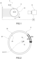
Figure 1 represents a schematic top view of an apparatus for inspecting transparent cylindrical containers containing transparent or semi-transparent viscous or gel products according to an embodiment of the present invention; -
Figures 2-6 show schematizations from above of an inspection apparatus according to the present invention, in successive inspection steps, as well as of the operating principles of said inspection apparatus, as better described below. - Elements or parts of elements common to the embodiments described hereinafter will be indicated with the same numerical references.
- With reference to the aforementioned figures, the
reference numeral 4 globally indicates an apparatus for inspecting transparentcylindrical containers 8 containing transparent or semi-transparent viscous or gel products, in particular for medical applications. - It should be pointed out that the
cylindrical containers 8 are transparent, so as to allow viewing from the outside of the substances, preferably transparent or semi-transparent viscous or gel, contained therein. - Therefore, said
cylindrical containers 8 are preferably made of glass or plastic, such as for example Plexiglass. - Furthermore, the
cylindrical containers 8 have an axisymmetry axis X-X; in other words, they are solids of rotation around said axisymmetry axis X-X. - Said
inspection apparatus 4 comprises a support and/or gripping device (not shown) for acylindrical container 8, suitable for supporting it and provided with means for making it rotate about a vertical rotation axis Y-Y, coincident with the cylindrical axisymmetry axis X-X of saidcylindrical container 8. - For the purposes of the present invention, it is possible to use a plurality of support and/or gripping devices for the
cylindrical containers 8; care should be taken so that said support and/or gripping devices do not prevent the vision and therefore the verification of any impurities on thecylindrical container 8. For this purpose, support and gripping devices are preferred which grasp or in any case rotate the containers from their support base. There is a multitude of gripping devices/methods suitable for this purpose. For example, it is possible to implement a bottom-head grip of the bottle or by pliers at the neck of the bottle itself, etc. The important thing is that these devices rotate the cylindrical container around their main axis. - The
apparatus 4 further comprises avideo camera 12 directed so as to frame and capture images, for example in the form of pixels, of awindow 16 of aside wall 20 of thecylindrical container 8. - Obviously, due to the fact that the
cylindrical container 8 is transparent, thevideo camera 12 is able to capture images not only of theside wall 20 of thecylindrical container 8 but also of its contents (preferably transparent or semi-transparent viscous gels or liquids). The object of the present invention is in fact to detect the presence of impurities and then to distinguish whether such possible impurities are outside, i.e. on anexternal surface 22 of theside wall 20, or inside, i.e. on aninternal surface 23 of theside wall 20 of thecylindrical container 8. If the impurity is on theinternal surface 23, then it will be in direct contact with the liquid contained in thecylindrical container 8 which must necessarily be discarded. - Said
side wall 20 has a thickness equal to the difference between an outer radius Re, i.e. a radius of theouter surface 22 of theside wall 20, with respect to the cylindrical axisymmetry axis X-X, and an inner radius Ri, i.e. a radius of theinner surface 23 of theside wall 20. - The
apparatus 4 further comprises alighting device 24, placed opposite thevideo camera 12 with respect to thecylindrical container 8, so as to back-light saidcylindrical container 8. - The
lighting device 24 is, for example, a flat lighting panel. - The
apparatus 4 further comprises acontrol unit 32 operatively connected to the support and/or gripping device and to thevideo camera 12, and programmed to: - control the rotation of the
cylindrical container 8 by means of the support and/or gripping device at constant angular speed around the vertical rotation axis Y-Y (Figures 2-3 ), - control the activation of the
video camera 12 so as to acquire 'n' images ofsaid window 16, for a predetermined number 'n' of regular angular intervals Δθ, - identify points (Pi) of said images which can be catalogued as impurities,
- measure a median displacement ΔSmed of each of said points Pi during said regular angular intervals Δθ and comparing it to a discriminating value equal to the product of the internal radius Ri of the
cylindrical container 8 for said regular angular intervals Δθ, - classify the impurity identified by the point Pi as external to the
container 8 if said median displacement ΔSmed of the point Pi is greater than said discriminating value and vice versa. - Preferably, the
control unit 32 is operatively connected to thelighting device 24, so as to be able to control the switching on thereof, coordinating it with the angular rotation of thecylindrical container 8. - According to a possible embodiment, the support and/or gripping device is provided with a rotary encoder to measure the rotation of the
cylindrical container 8. Preferably, said rotary encoder is operatively connected to thecontrol unit 32 to measure the median displacement ΔSmed of each of said points Pi. - According to a preferred embodiment (
Figures 5-6 ), thecontrol unit 32 is programmed so as to place a focal plane of thevideo camera 12 on theside wall 20 of thecylindrical container 8 opposite thevideo camera 12, i.e., on the side of thelighting device 24, in such a way as to exploit the lens or magnification effect M, due to the presence, inside thecylindrical container 8, of any transparent product having a refractive index different from the refractive index of air. - In particular, said lens effect is equal to M = f/(f-s)
- wherein f = nl/2(nl-1)2 where nl is the refractive index of the viscous product contained in the cylindrical container (8),
- where 's' is equal to said outer radius Re of the
cylindrical container 8, - and wherein the
video camera 12 is placed at a distance 'f' from the cylindrical axisymmetry axis X-X of saidcylindrical container 8, opposite thelighting device 24. - Preferably, the
control unit 32 is programmed to measure only the trajectories inherent to points Pi on the side of thecylindrical container 8 opposite thevideo camera 12 and facing the lighting device 24 (Figure 6 ). - The angular intervals with which the linear video camera scans the extension of the
container 8 depend on the resolution, in the extension direction of the container itself, to be applied. A value for said angular intervals may be, by way of example, equal to 0.044 degrees, obtained by dividing the 360 °rotation angle of the container by 8192 encoder pulses (360°/8192). - The regular angular intervals are therefore, by way of example, angular intervals of 0.05 sexagesimal degrees.
- The operation of the inspection apparatus according to the present invention shall now be described.
- In particular, the principle on which the present invention is based starts from the assumption that a contaminant attached to the
outer surface 22 of theside wall 20, if rotated, will travel a greater distance than that traveled by a contaminant attached to theinner surface 23 of the side wall or in any case arranged in suspension inside thecylindrical container 8. - In particular, it is essential to identify a certain criterion that allows contaminants contained inside the
container 8 to be discriminated from those attached to theouter surface 22 of thecontainer 8 itself. - The
cylindrical container 8 is placed in front of thevideo camera 12 in a vertical position and made to rotate around the vertical rotation axis Y-Y, parallel and coincident with the cylindrical axisymmetry axis X-X, at constant angular speed. Thecylindrical container 8 is in the meantime backlit by thelighting device 24, for example a flat LED illuminator, placed on the opposite side of the video camera 12 (Figure 1 ). - During the rotation of the container, the camera captures images at constant angular intervals Δθ.
- Here are some geometries of the system (schematically illustrated in
Figure 2 ): - ri: radius of the
inner surface 23 of thecylindrical container 8; - re: radius of the
outer surface 22 of thecylindrical container 8; - ΔSi = ri * Δθ is the space traveled by an object placed on the
outer surface 22 of thecylindrical container 8 at an angular variation Δθ; - ΔSe = re * Δθ is the space traveled by an object placed on the
inner surface 23 of thecylindrical container 8 at an angular variation Δθ. - To discriminate an internal object from one external to the
cylindrical container 8 it is sufficient to evaluate the space traveled by the object (i.e. by the impurity) at each fixed angular variation. - With the same angular variation Δθ, having set ri < re, we will have ΔSe > ΔSi.
- An object contained within the
cylindrical container 8 will have a radius of rotation (distance from the rotation axis) which will range from 0, in the case of an object perfectly aligned, to ri, when the object is in contact with theinner surface 23 of thecylindrical container 8. - An object on the
outer surface 22 of thecylindrical container 8 will have a radius of rotation (distance from the rotation axis) equal to re. - As a consequence of an angular displacement Δθ, an object inside the
cylindrical container 8 will have undergone a displacement:

- On the contrary, an object on the
outer surface 22 of thecylindrical container 8 will undergo a displacement equal to:

- The difference between the two displacements, in the worst case in which an object in contact with the
inner surface 23 must be distinguished from one in contact with theouter surface 22, is equal to ΔSe - ΔSi = (re - ri)*Δθ the variation, with the same angular displacement, is therefore equal to re - ri, therefore to the thickness of theside wall 20 of thecylindrical container 8. - The
video camera 12 will capture (n) images in sequence every Δθ degrees through the use of a rotary encoder connected to the motor which rotates the container. - It therefore remains to evaluate the displacement ΔS of a contaminant that has undergone a displacement. For this reason, a tracking algorithm has been implemented which deals with relating the positions of the same object at different instants, thus tracing the movement trajectory thereof.
- The trajectory of the moving contaminant will contain the positions of the latter in the different images.
- Having set p, a subset of n, the captured images in which the object is visible from the camera: 1,2,..., p, in the instants: t1, t2,..., tp
- We will therefore have:
- ΔS1: displacement of the object in the transition from
image 1 toimage 2 - ΔS2: displacement of the object in the transition from
image 2 toimage 3 - ΔSp-1: displacement of the object in the transition from image p-1 to image p
- At this point we will calculate the median value ΔSmed of all ΔS1..p-1, of each moving object.
- It is known by construction that, given an angular displacement Δθ, no object inside the
cylindrical container 8 will be able to undergo a displacement greater than ΔSi = ri * Δθ. - Therefore, any contaminant whose trajectory will have a median value ΔSmed of the displacements in the various instants greater than ΔSi = ri * Δθ will be marked as an "external contaminant".
- Whereby if:
ΔSmed > ΔSi = ri * Δθ => then the contaminant is external to thecylindrical container 8. - A limiting example, in which the internal contaminant is precisely in contact with the
inner surface 23 of theside wall 20 of thecylindrical container 8 is illustrated inFigure 3 . - Possible trajectories calculated for an internal contaminant (i) and an external contaminant (e) are illustrated in
Figure 4 , where i1, i2, i3, ..., ip are the positions at various instants of the internal contaminant, while e1, e2, e3, ..., and p are the positions of the external contaminant at various instants. - It will therefore result:


- The difference between ΔSimed and ΔSemed is equal to ΔSe - ΔSi = (re - ri)*Δθ.
- Obviously, this difference is particularly small, since the thickness of the cylindrical container is very thin. Therefore, in order to solve this difference, a high resolution, high
frame rate camera 12 may be used. - Alternatively, it is possible to amplify this difference, so as to use
video cameras 12 with lower resolution and lower frame rates. - In particular (
Figure 5 ) to amplify the difference ΔSe - ΔSi = (re - ri)*Δθ, the magnification due to the contained product was exploited. The magnification effect was therefore exploited:

- With focal f of the lens (i.e. the
cylindrical container 8 which acts as a lens) equal to:
f = nl2/(nl-1)2 where nl is the refractive index of the viscous product contained in thecylindrical container 8. - The magnification obtained is equal to a factor of about 2.
- Therefore, the focal plane of the
video camera 12 is placed on the surface of the side opposite thevideo camera 12 itself, in such a way as to exploit the lens effect, due to the presence of any transparent product with a refractive index different from that of air. - There is therefore a trajectory on the
opposite side 34 to thevideo camera 12 and a trajectory on thefront side 38 with respect to the video camera: thetrajectory 34 on the opposite side of thevideo camera 12 benefits from the magnification effect (lens) described above (Figure 6 ). - The consequent magnification allowed the use of the system avoiding obstacles deriving from the need for
video cameras 12 with higher resolution and therefore at lower frame rates, which could not meet the capture speed requirements necessary to track and follow every visible contaminant. - Therefore, only the trajectories inherent to the side of the container opposite the chamber are considered (
Figure 6 ). - As may be seen from the above description, the inspection apparatus and method according to the invention allow the drawbacks of the prior art to be overcome.
- In particular, the present invention allows the contaminants present inside the container (unacceptable for the purposes of the test) to be detected, discriminating them from contaminants present outside the container (considered acceptable).
- This implies a drastic lowering of the false rejections due to the detection of dirt, fibers and other which are not in contact with the pharmaceutical product as they are arranged outside the containers.
- The "Spin and stop" approach cannot work as the liquid, being viscous or GEL, would not continue to rotate after the container stops. The contained particle would therefore not have a motion relative to the container itself after the latter has stopped. So the contaminants on the outside of the container would be as stationary as those inside in the viscous liquid/gel. A cosmetic approach, therefore with continuous rotation and rotating image acquisition, makes the contained contaminant detectable.
- Since this process is able to distinguish the position, external or internal, of the contaminant, it allows containers with transparent or semi-transparent viscous or gel liquids to be analyzed with a cosmetic approach, drastically reducing the false rejections due to external dirt.
- Those skilled in the art may make several changes and adjustments to the inspection apparatus and methods described above in order to meet specific and incidental needs, all falling within the scope of protection as defined in the following claims.
Claims (13)
- Apparatus (4) for inspecting transparent, cylindrical containers (8) containing transparent or semi-transparent viscous or gel products, in particular for medical applications, comprising:- a support and/or gripping device for a cylindrical container (8), suitable for supporting it and provided with means for making it rotate about a vertical rotation axis (Y-Y), coincident with a cylindrical axisymmetry axis (X-X) of said cylindrical container (8),- a video camera (12) directed so as to frame and capture images of a window (16) of a side wall (20) of the cylindrical container (8),- said side wall (20) having a thickness equal to the difference between an outer radius (Re), i.e. a radius of an outer surface of the side wall (20), with respect to the cylindrical axisymmetry axis (X-X), and an inner radius (Ri), i.e. a radius of an inner surface of the side wall (20),- a lighting device (24), placed opposite the video camera (12) with respect to the cylindrical container (8), so as to back-light said cylindrical container (8),- a control unit (32) operatively connected to the support and/or gripping device and to the video camera (12), and programmed to:- control the rotation of the cylindrical container (8) by means of the support and/or gripping device at constant angular speed around the vertical rotation axis (Y-Y),- control the activation of the video camera (12) so as to acquire a plurality of 'n' images of said window (16), for a predetermined number 'n' of regular angular intervals (Δθ),- identify points (Pi) of said images which can be catalogued as impurities, characterized in that the control unit (32) is further programmed to- measure a median displacement (ΔSmed) of each of said points (Pi) during said regular angular intervals Δθ and compare it to a discriminating value equal to the product of the internal radius (Ri) of the cylindrical container (8) and said regular angular intervals (Δθ), and- classify the impurity identified by the point (Pi) as external to the container (8) if said median displacement (ΔSmed) of the point (Pi) is greater than said discriminating value and vice versa.
- The apparatus (4) according to claim 1, wherein the control unit (32) is operatively connected to the lighting device (24).
- The apparatus (4) according to claim 1 or 2, wherein the support and/or gripping device is provided with a rotary encoder to measure the rotation of the cylindrical container (8), said rotary encoder being operatively connected to the control unit (32) to measure the median displacement (ΔSmed) of each of said points (Pi).
- The apparatus (4) according to claim 1, 2 or 3, wherein the control unit (32) is programmed to:- place a focal plane of the video camera (12) on the side wall (20) of the cylindrical container (8) opposite the video camera (12), i.e., on the side of the lighting device (24), in such a way as to exploit the lens or magnification effect (M), due to the presence, inside the cylindrical container (8), of any transparent product having a refractive index different from the refractive index of air.
- The apparatus (4) according to claim 4, wherein said lens effect is equal to a M =f/(f-s)- wherein f =nl/2(nl-1)2 where nl is the refractive index of the viscous product contained in the cylindrical container (8),- wherein 's' is equal to said outer radius (Re),- and wherein the video camera (12) is placed at a distance 'f' from the cylindrical axisymmetry axis (X-X) of said cylindrical container (8), opposite the lighting device (24).
- The apparatus (4) according to claim 4 or 5, wherein the control unit (32) is programmed to measure only the trajectories inherent to points (Pi) on the side of the cylindrical container (8) opposite the video camera (12) and facing the lighting device (24).
- The apparatus (4) according to any of the claims from 1 to 6, wherein said regular angular intervals are angular intervals of 0.05 sexagesimal degrees.
- The apparatus (4) according to any of the claims from 1 to 7, wherein the lighting device (24) is a flat lighting panel.
- Method for inspecting transparent, cylindrical containers (8) containing transparent or semi-transparent viscous or gel products, in particular for medical applications, comprising the steps of:- providing a transparent cylindrical container (8) containing a transparent or semi-transparent viscous or gel product, supported so as to rotate around a vertical axis of rotation (Y-Y), coinciding with an axisymmetry axis (X-X) of said container (8),- providing a support and/or gripping device for said cylindrical container (8), suitable for supporting it and provided with means for making it rotate about a vertical rotation axis (Y-Y), coinciding with a cylindrical axisymmetry axis (X-X) of said cylindrical container (8),- providing a video camera (12) directed so as to frame and capture images of a window (16) of a side wall (20) of the cylindrical container (8), said side wall (20) having a thickness equal to the difference between an outer radius (Re), i.e. a radius of an outer surface of the side wall (20), with respect to the cylindrical axisymmetry axis (X-X), and an inner radius (Ri), i.e. a radius of an inner surface of the side wall (20),- providing a lighting device (24), placed opposite the video camera (12) with respect to the cylindrical container (8), so as to back-light said cylindrical container (8),- controlling the rotation of the cylindrical container (8) by means of the support and/or gripping device at constant angular speed around the vertical rotation axis (Y-Y),- controlling the activation of the video camera (12) so as to acquire a plurality of 'n' images of said window (16), for a predetermined number 'n' of regular angular intervals Δθ,- identifying points (Pi) of said images which can be catalogued as impurities, characterized in that the method further comprises the steps of- measuring a median displacement (ΔSmed) of each of said points (Pi) during said regular angular intervals Δθ) and comparing it to a discriminating value equal to the product of the internal radius (Ri) of the cylindrical container (8) and said regular angular intervals (Δθ),- classifying the impurity identified by the point (Pi) as external to the container (8) if said median displacement (ΔSmed) of the point (Pi) is greater than said discriminating value and vice versa.
- Method according to claim 9, comprising the step of placing a focal plane of the video camera (12) on the side wall (20) of the cylindrical container (8) opposite the video camera (12), i.e., on the side of the lighting device (24), in such a way as to exploit the lens or magnification effect (M), due to the presence, inside the container (8), of any transparent product having a refractive index different from the refractive index of air.
- The method according to claim 10, wherein said lens effect is equal to M =f/(f-s)- wherein f =nl/2(nl-1)2 where nl is the refractive index of the viscous product contained in the container (8),- where 's' is equal to said outer radius (Re),- and wherein the video camera (12) is placed at a distance 'f' from the cylindrical axisymmetry axis (X-X) of said cylindrical container (8), opposite the lighting device (24).
- The method according to claim 10 or 11, wherein only the trajectories inherent to points (Pi) on the side of the container opposite the video camera (12) and facing the lighting device (24) are measured.
- The method according to any of the claims from 9 to 12, wherein said regular angular intervals are angular intervals of 0.05 sexagesimal degrees.
Applications Claiming Priority (1)
| Application Number | Priority Date | Filing Date | Title |
|---|---|---|---|
| IT102020000031394A IT202000031394A1 (en) | 2020-12-18 | 2020-12-18 | APPARATUS AND METHOD FOR INSPECTING CLEAR CYLINDRICAL CONTAINERS CONTAINING CLEAR OR SEMI-TRANSPARENT GEL OR VISCOUS PRODUCTS, PARTICULARLY FOR MEDICAL APPLICATIONS |
Publications (3)
| Publication Number | Publication Date |
|---|---|
| EP4016059A1 EP4016059A1 (en) | 2022-06-22 |
| EP4016059C0 EP4016059C0 (en) | 2025-07-02 |
| EP4016059B1 true EP4016059B1 (en) | 2025-07-02 |
Family
ID=75111665
Family Applications (1)
| Application Number | Title | Priority Date | Filing Date |
|---|---|---|---|
| EP21211775.8A Active EP4016059B1 (en) | 2020-12-18 | 2021-12-01 | Apparatus and method for inspecting transparent cylindrical containers containing transparent or semi-transparent viscous or gel products, in particular for medical applications |
Country Status (5)
| Country | Link |
|---|---|
| US (1) | US11971362B2 (en) |
| EP (1) | EP4016059B1 (en) |
| JP (1) | JP7821599B2 (en) |
| CN (1) | CN114646644A (en) |
| IT (1) | IT202000031394A1 (en) |
Families Citing this family (1)
| Publication number | Priority date | Publication date | Assignee | Title |
|---|---|---|---|---|
| CN116930203A (en) * | 2023-07-07 | 2023-10-24 | 浙江环稠机械设备制造有限公司 | Method for detecting graduation marks of injector |
Family Cites Families (20)
| Publication number | Priority date | Publication date | Assignee | Title |
|---|---|---|---|---|
| JPS6388431A (en) * | 1986-10-02 | 1988-04-19 | Hitachi Plant Eng & Constr Co Ltd | Foreign matter detecting method and apparatus therefor |
| JPS63109352A (en) * | 1986-10-28 | 1988-05-14 | Toyo Glass Kk | Apparatus for inspecting flaw of transparent container |
| JPH1137952A (en) * | 1997-07-14 | 1999-02-12 | Yamamura Glass Co Ltd | Bottle inspection system |
| NL1022810C2 (en) * | 2003-02-28 | 2004-08-31 | Heineken Tech Services | Method and system for inspecting packaging. |
| JP2005070013A (en) * | 2003-08-28 | 2005-03-17 | Hitachi Eng Co Ltd | Container foreign matter inspection method |
| US7430047B2 (en) * | 2004-03-09 | 2008-09-30 | Gerald Walter Budd | Small container fluid dynamics to produce optimized inspection conditions |
| EP1934585B1 (en) * | 2005-10-15 | 2010-04-28 | Udviklingsselskabet Innoscan K/S | Method and system for irradiating and inspecting liquid-carrying containers |
| JP2008216016A (en) * | 2007-03-02 | 2008-09-18 | Honda Motor Co Ltd | Rotation angle calculation device and displacement amount calculation device |
| JP5636211B2 (en) * | 2010-05-31 | 2014-12-03 | 株式会社 日立産業制御ソリューションズ | Foreign matter inspection apparatus and foreign matter inspection method |
| IT1402103B1 (en) * | 2010-10-08 | 2013-08-28 | Università Di Pisa | METHOD AND DEVICE TO DETECT THE GEOMETRIC POSITION OF A DEFECT IN AN OBJECT |
| US8941825B2 (en) * | 2013-03-15 | 2015-01-27 | Owens-Brockway Glass Container Inc. | Container inspection |
| DE102014217771B4 (en) * | 2014-09-05 | 2023-05-04 | Fraunhofer-Gesellschaft zur Förderung der angewandten Forschung e.V. | Device and method for quality control of transparent objects |
| US10393670B1 (en) * | 2016-05-19 | 2019-08-27 | Applied Vision Corporation | Container inspection system |
| DE102016114190A1 (en) | 2016-08-01 | 2018-02-01 | Schott Schweiz Ag | Method and device for the optical examination of transparent bodies |
| WO2018044328A1 (en) * | 2016-09-02 | 2018-03-08 | Amgen Inc. | Video trigger synchronization for improved particle detection in a vessel |
| CN109844505B (en) | 2016-09-30 | 2021-10-26 | 东洋玻璃株式会社 | Burn inspection device for glass container |
| US10337977B1 (en) * | 2016-11-22 | 2019-07-02 | Corning Incorporated | Systems and methods for glass particle detection |
| JP2018151266A (en) * | 2017-03-13 | 2018-09-27 | 日本電気硝子株式会社 | Inspection method of glass tube |
| JP7116419B2 (en) * | 2018-10-04 | 2022-08-10 | 国立研究開発法人産業技術総合研究所 | Particle measuring device, calibration method, and measuring device |
| IL315838A (en) | 2018-12-17 | 2024-11-01 | Amgen Inc | Sheet lighting for particle detection in drug product containers |
-
2020
- 2020-12-18 IT IT102020000031394A patent/IT202000031394A1/en unknown
-
2021
- 2021-12-01 EP EP21211775.8A patent/EP4016059B1/en active Active
- 2021-12-02 US US17/540,784 patent/US11971362B2/en active Active
- 2021-12-03 JP JP2021196837A patent/JP7821599B2/en active Active
- 2021-12-17 CN CN202111552748.9A patent/CN114646644A/en active Pending
Non-Patent Citations (1)
| Title |
|---|
| MIKKEL KRAGH ET AL: "3D impurity inspection of cylindrical transparent containers", MEASUREMENT SCIENCE AND TECHNOLOGY, IOP, BRISTOL, GB, vol. 28, no. 1, 6 December 2016 (2016-12-06), pages 17002, XP020311973, ISSN: 0957-0233, [retrieved on 20161206], DOI: 10.1088/1361-6501/28/1/017002 * |
Also Published As
| Publication number | Publication date |
|---|---|
| US20220196566A1 (en) | 2022-06-23 |
| EP4016059A1 (en) | 2022-06-22 |
| EP4016059C0 (en) | 2025-07-02 |
| US11971362B2 (en) | 2024-04-30 |
| CN114646644A (en) | 2022-06-21 |
| JP7821599B2 (en) | 2026-02-27 |
| JP2022097400A (en) | 2022-06-30 |
| IT202000031394A1 (en) | 2022-06-18 |
Similar Documents
| Publication | Publication Date | Title |
|---|---|---|
| US5926268A (en) | System and method for stress detection in a molded container | |
| JP7490655B2 (en) | Sheet illumination for particle detection in pharmaceutical containers | |
| NO309213B1 (en) | Method and apparatus for inspecting liquid-filled containers | |
| WO1997046329A9 (en) | System and method for stress detection in a molded container | |
| WO2000039568A9 (en) | Machine vision system and method for non-contact container inspection | |
| JP2019523424A (en) | Method and apparatus for optical inspection of a transparent body | |
| EP3341712B1 (en) | Object multi-perspective inspection apparatus and method therefor | |
| EP2685209A1 (en) | Glass bottle inspection device and telecentric lens unit | |
| US8670032B2 (en) | Device and method for inspecting bottles or similar containers | |
| EP4016059A1 (en) | Apparatus and method for inspecting transparent cylindrical containers containing transparent or semi-transparent viscous or gel products, in particular for medical applications | |
| EP2584307B1 (en) | Glass bottle inspection device | |
| US11703451B2 (en) | Apparatus and method for inspecting transparent cylindrical containers containing milky products, in particular for medical applications | |
| EP2623928A1 (en) | Glass bottle inspection device | |
| EP1955055B1 (en) | Apparatus and method for ensuring rotation of a container during inspection | |
| CN120039810A (en) | Method and device for checking a container closure mounted on a container | |
| KR20250167167A (en) | Syringe foreign matter inspection system | |
| HK40114591A (en) | Sheet lighting for particle detection in drug product containers | |
| CN120435651A (en) | Non-contact online inspection method for containers and station for implementing the method | |
| Wolf | Laser scanning techniques for automatic inspection of heat-sealed film packages |
Legal Events
| Date | Code | Title | Description |
|---|---|---|---|
| PUAI | Public reference made under article 153(3) epc to a published international application that has entered the european phase |
Free format text: ORIGINAL CODE: 0009012 |
|
| STAA | Information on the status of an ep patent application or granted ep patent |
Free format text: STATUS: THE APPLICATION HAS BEEN PUBLISHED |
|
| AK | Designated contracting states |
Kind code of ref document: A1 Designated state(s): AL AT BE BG CH CY CZ DE DK EE ES FI FR GB GR HR HU IE IS IT LI LT LU LV MC MK MT NL NO PL PT RO RS SE SI SK SM TR |
|
| STAA | Information on the status of an ep patent application or granted ep patent |
Free format text: STATUS: REQUEST FOR EXAMINATION WAS MADE |
|
| 17P | Request for examination filed |
Effective date: 20221213 |
|
| RBV | Designated contracting states (corrected) |
Designated state(s): AL AT BE BG CH CY CZ DE DK EE ES FI FR GB GR HR HU IE IS IT LI LT LU LV MC MK MT NL NO PL PT RO RS SE SI SK SM TR |
|
| P01 | Opt-out of the competence of the unified patent court (upc) registered |
Effective date: 20230526 |
|
| GRAP | Despatch of communication of intention to grant a patent |
Free format text: ORIGINAL CODE: EPIDOSNIGR1 |
|
| STAA | Information on the status of an ep patent application or granted ep patent |
Free format text: STATUS: GRANT OF PATENT IS INTENDED |
|
| INTG | Intention to grant announced |
Effective date: 20250327 |
|
| GRAS | Grant fee paid |
Free format text: ORIGINAL CODE: EPIDOSNIGR3 |
|
| GRAA | (expected) grant |
Free format text: ORIGINAL CODE: 0009210 |
|
| STAA | Information on the status of an ep patent application or granted ep patent |
Free format text: STATUS: THE PATENT HAS BEEN GRANTED |
|
| AK | Designated contracting states |
Kind code of ref document: B1 Designated state(s): AL AT BE BG CH CY CZ DE DK EE ES FI FR GB GR HR HU IE IS IT LI LT LU LV MC MK MT NL NO PL PT RO RS SE SI SK SM TR |
|
| REG | Reference to a national code |
Ref country code: GB Ref legal event code: FG4D |
|
| REG | Reference to a national code |
Ref country code: CH Ref legal event code: EP |
|
| REG | Reference to a national code |
Ref country code: DE Ref legal event code: R096 Ref document number: 602021033256 Country of ref document: DE |
|
| REG | Reference to a national code |
Ref country code: IE Ref legal event code: FG4D |
|
| U01 | Request for unitary effect filed |
Effective date: 20250702 |
|
| U07 | Unitary effect registered |
Designated state(s): AT BE BG DE DK EE FI FR IT LT LU LV MT NL PT RO SE SI Effective date: 20250709 |
|
| PG25 | Lapsed in a contracting state [announced via postgrant information from national office to epo] |
Ref country code: IS Free format text: LAPSE BECAUSE OF FAILURE TO SUBMIT A TRANSLATION OF THE DESCRIPTION OR TO PAY THE FEE WITHIN THE PRESCRIBED TIME-LIMIT Effective date: 20251102 |
|
| PGFP | Annual fee paid to national office [announced via postgrant information from national office to epo] |
Ref country code: GB Payment date: 20251219 Year of fee payment: 5 |
|
| PG25 | Lapsed in a contracting state [announced via postgrant information from national office to epo] |
Ref country code: NO Free format text: LAPSE BECAUSE OF FAILURE TO SUBMIT A TRANSLATION OF THE DESCRIPTION OR TO PAY THE FEE WITHIN THE PRESCRIBED TIME-LIMIT Effective date: 20251002 |
|
| PG25 | Lapsed in a contracting state [announced via postgrant information from national office to epo] |
Ref country code: HR Free format text: LAPSE BECAUSE OF FAILURE TO SUBMIT A TRANSLATION OF THE DESCRIPTION OR TO PAY THE FEE WITHIN THE PRESCRIBED TIME-LIMIT Effective date: 20250702 |
|
| PG25 | Lapsed in a contracting state [announced via postgrant information from national office to epo] |
Ref country code: GR Free format text: LAPSE BECAUSE OF FAILURE TO SUBMIT A TRANSLATION OF THE DESCRIPTION OR TO PAY THE FEE WITHIN THE PRESCRIBED TIME-LIMIT Effective date: 20251003 |
|
| PG25 | Lapsed in a contracting state [announced via postgrant information from national office to epo] |
Ref country code: CZ Free format text: LAPSE BECAUSE OF FAILURE TO SUBMIT A TRANSLATION OF THE DESCRIPTION OR TO PAY THE FEE WITHIN THE PRESCRIBED TIME-LIMIT Effective date: 20250702 |
|
| PG25 | Lapsed in a contracting state [announced via postgrant information from national office to epo] |
Ref country code: PL Free format text: LAPSE BECAUSE OF FAILURE TO SUBMIT A TRANSLATION OF THE DESCRIPTION OR TO PAY THE FEE WITHIN THE PRESCRIBED TIME-LIMIT Effective date: 20250702 |
|
| PG25 | Lapsed in a contracting state [announced via postgrant information from national office to epo] |
Ref country code: RS Free format text: LAPSE BECAUSE OF FAILURE TO SUBMIT A TRANSLATION OF THE DESCRIPTION OR TO PAY THE FEE WITHIN THE PRESCRIBED TIME-LIMIT Effective date: 20251002 |
|
| PG25 | Lapsed in a contracting state [announced via postgrant information from national office to epo] |
Ref country code: ES Free format text: LAPSE BECAUSE OF FAILURE TO SUBMIT A TRANSLATION OF THE DESCRIPTION OR TO PAY THE FEE WITHIN THE PRESCRIBED TIME-LIMIT Effective date: 20250702 |
|
| U20 | Renewal fee for the european patent with unitary effect paid |
Year of fee payment: 5 Effective date: 20251230 |
|
| PG25 | Lapsed in a contracting state [announced via postgrant information from national office to epo] |
Ref country code: SM Free format text: LAPSE BECAUSE OF FAILURE TO SUBMIT A TRANSLATION OF THE DESCRIPTION OR TO PAY THE FEE WITHIN THE PRESCRIBED TIME-LIMIT Effective date: 20250702 |
|
| PG25 | Lapsed in a contracting state [announced via postgrant information from national office to epo] |
Ref country code: SK Free format text: LAPSE BECAUSE OF FAILURE TO SUBMIT A TRANSLATION OF THE DESCRIPTION OR TO PAY THE FEE WITHIN THE PRESCRIBED TIME-LIMIT Effective date: 20250702 |
|
| PLBE | No opposition filed within time limit |
Free format text: ORIGINAL CODE: 0009261 |
|
| STAA | Information on the status of an ep patent application or granted ep patent |
Free format text: STATUS: NO OPPOSITION FILED WITHIN TIME LIMIT |
|
| REG | Reference to a national code |
Ref country code: CH Ref legal event code: L10 Free format text: ST27 STATUS EVENT CODE: U-0-0-L10-L00 (AS PROVIDED BY THE NATIONAL OFFICE) Effective date: 20260518 |
|
| 26N | No opposition filed |
Effective date: 20260407 |
|
| PG25 | Lapsed in a contracting state [announced via postgrant information from national office to epo] |
Ref country code: MC Free format text: LAPSE BECAUSE OF FAILURE TO SUBMIT A TRANSLATION OF THE DESCRIPTION OR TO PAY THE FEE WITHIN THE PRESCRIBED TIME-LIMIT Effective date: 20250702 |
|
| REG | Reference to a national code |
Ref country code: CH Ref legal event code: H13 Free format text: ST27 STATUS EVENT CODE: U-0-0-H10-H13 (AS PROVIDED BY THE NATIONAL OFFICE) Effective date: 20260723 |