EP4016016A1 - Optical system and plane spectroscopic device - Google Patents
Optical system and plane spectroscopic device Download PDFInfo
- Publication number
- EP4016016A1 EP4016016A1 EP21213503.2A EP21213503A EP4016016A1 EP 4016016 A1 EP4016016 A1 EP 4016016A1 EP 21213503 A EP21213503 A EP 21213503A EP 4016016 A1 EP4016016 A1 EP 4016016A1
- Authority
- EP
- European Patent Office
- Prior art keywords
- reflecting portion
- optical system
- curved
- light
- surface mirror
- Prior art date
- Legal status (The legal status is an assumption and is not a legal conclusion. Google has not performed a legal analysis and makes no representation as to the accuracy of the status listed.)
- Pending
Links
Images


Classifications
-
- G—PHYSICS
- G01—MEASURING; TESTING
- G01J—MEASUREMENT OF INTENSITY, VELOCITY, SPECTRAL CONTENT, POLARISATION, PHASE OR PULSE CHARACTERISTICS OF INFRARED, VISIBLE OR ULTRAVIOLET LIGHT; COLORIMETRY; RADIATION PYROMETRY
- G01J3/00—Spectrometry; Spectrophotometry; Monochromators; Measuring colours
- G01J3/02—Details
- G01J3/0205—Optical elements not provided otherwise, e.g. optical manifolds, diffusers, windows
- G01J3/021—Optical elements not provided otherwise, e.g. optical manifolds, diffusers, windows using plane or convex mirrors, parallel phase plates, or particular reflectors
-
- G—PHYSICS
- G02—OPTICS
- G02B—OPTICAL ELEMENTS, SYSTEMS OR APPARATUS
- G02B17/00—Systems with reflecting surfaces, with or without refracting elements
- G02B17/02—Catoptric systems, e.g. image erecting and reversing system
- G02B17/06—Catoptric systems, e.g. image erecting and reversing system using mirrors only, i.e. having only one curved mirror
- G02B17/0647—Catoptric systems, e.g. image erecting and reversing system using mirrors only, i.e. having only one curved mirror using more than three curved mirrors
- G02B17/0652—Catoptric systems, e.g. image erecting and reversing system using mirrors only, i.e. having only one curved mirror using more than three curved mirrors on-axis systems with at least one of the mirrors having a central aperture
-
- G—PHYSICS
- G01—MEASURING; TESTING
- G01J—MEASUREMENT OF INTENSITY, VELOCITY, SPECTRAL CONTENT, POLARISATION, PHASE OR PULSE CHARACTERISTICS OF INFRARED, VISIBLE OR ULTRAVIOLET LIGHT; COLORIMETRY; RADIATION PYROMETRY
- G01J3/00—Spectrometry; Spectrophotometry; Monochromators; Measuring colours
- G01J3/02—Details
- G01J3/0205—Optical elements not provided otherwise, e.g. optical manifolds, diffusers, windows
- G01J3/0243—Optical elements not provided otherwise, e.g. optical manifolds, diffusers, windows having a through-hole enabling the optical element to fulfil an additional optical function, e.g. a mirror or grating having a throughhole for a light collecting or light injecting optical fiber
-
- G—PHYSICS
- G01—MEASURING; TESTING
- G01J—MEASUREMENT OF INTENSITY, VELOCITY, SPECTRAL CONTENT, POLARISATION, PHASE OR PULSE CHARACTERISTICS OF INFRARED, VISIBLE OR ULTRAVIOLET LIGHT; COLORIMETRY; RADIATION PYROMETRY
- G01J3/00—Spectrometry; Spectrophotometry; Monochromators; Measuring colours
- G01J3/28—Investigating the spectrum
- G01J3/2803—Investigating the spectrum using photoelectric array detector
-
- G—PHYSICS
- G01—MEASURING; TESTING
- G01N—INVESTIGATING OR ANALYSING MATERIALS BY DETERMINING THEIR CHEMICAL OR PHYSICAL PROPERTIES
- G01N21/00—Investigating or analysing materials by the use of optical means, i.e. using sub-millimetre waves, infrared, visible or ultraviolet light
- G01N21/17—Systems in which incident light is modified in accordance with the properties of the material investigated
- G01N21/25—Colour; Spectral properties, i.e. comparison of effect of material on the light at two or more different wavelengths or wavelength bands
- G01N21/31—Investigating relative effect of material at wavelengths characteristic of specific elements or molecules, e.g. atomic absorption spectrometry
- G01N21/35—Investigating relative effect of material at wavelengths characteristic of specific elements or molecules, e.g. atomic absorption spectrometry using infrared light
-
- G—PHYSICS
- G02—OPTICS
- G02B—OPTICAL ELEMENTS, SYSTEMS OR APPARATUS
- G02B27/00—Optical systems or apparatus not provided for by any of the groups G02B1/00 - G02B26/00, G02B30/00
- G02B27/10—Beam splitting or combining systems
- G02B27/1006—Beam splitting or combining systems for splitting or combining different wavelengths
- G02B27/1013—Beam splitting or combining systems for splitting or combining different wavelengths for colour or multispectral image sensors, e.g. splitting an image into monochromatic image components on respective sensors
-
- G—PHYSICS
- G02—OPTICS
- G02B—OPTICAL ELEMENTS, SYSTEMS OR APPARATUS
- G02B27/00—Optical systems or apparatus not provided for by any of the groups G02B1/00 - G02B26/00, G02B30/00
- G02B27/10—Beam splitting or combining systems
- G02B27/14—Beam splitting or combining systems operating by reflection only
-
- G—PHYSICS
- G02—OPTICS
- G02B—OPTICAL ELEMENTS, SYSTEMS OR APPARATUS
- G02B27/00—Optical systems or apparatus not provided for by any of the groups G02B1/00 - G02B26/00, G02B30/00
- G02B27/10—Beam splitting or combining systems
- G02B27/14—Beam splitting or combining systems operating by reflection only
- G02B27/143—Beam splitting or combining systems operating by reflection only using macroscopically faceted or segmented reflective surfaces
-
- G—PHYSICS
- G01—MEASURING; TESTING
- G01N—INVESTIGATING OR ANALYSING MATERIALS BY DETERMINING THEIR CHEMICAL OR PHYSICAL PROPERTIES
- G01N2201/00—Features of devices classified in G01N21/00
- G01N2201/06—Illumination; Optics
- G01N2201/063—Illuminating optical parts
- G01N2201/0636—Reflectors
Definitions
- the present exemplary embodiments relate to an optical system and a plane spectroscopic device.
- an original image is more finely divided, higher-resolution information is obtainable, but it is not easy to one-dimensionally array divided images in a limited space.
- one of means is to spread a large number of optical fibers all over an image portion and to one-dimensionally rearrange the optical fibers by utilizing their flexibility, which is a highly excellent method by which a higher resolution is achieved through an increase of fine optical fibers.
- the transmittance of the optical fiber is not completely uniform, and it is difficult to extract original light information in a uniform state, due to, for example, a polarization state of light changes because of a curvature.
- An optical fiber generally includes a core portion through which light passes and a clad portion that causes total reflection, and has an optimum size depending on a wavelength to be transmitted.
- a method is available in which an image is spatially divided by a plurality of mirrors and the resultant image is one-dimensionally rearranged. There is a slight change in light characteristics due to reflection characteristics of the mirrors, but it is stable and it is easy to restore information.
- the plane division optical system is also effective in a case where an image is observed by a one-dimensional detector that is inexpensive and is capable of performing readout with high resolution at a high speed without using a two-dimensional detector.
- an optical system as specified in claims 1 to 7.
- a plane spectroscopic device as specified in claims 8 to 9.
- Fig. 1 illustrates a view of a field division optical system 100 of the first exemplary embodiment.
- the field division optical system 100 is an optical system that divides a light flux from a side of an object plane. As illustrated in Fig. 1 , the field division optical system 100 roughly includes four groups of mirrors in order from an incident direction of an incident light flux to be divided.
- the field division optical system 100 includes a first reflecting portion 1, a second reflecting portion 2, a third reflecting portion 3, and a fourth reflecting portion 4.
- the first reflecting portion 1 is a curved-surface mirror having a curved reflective surface, and is provided with an opening through which the light flux from the object plane passes or a transmitting portion 1a through which the light flux is transmitted.
- the opening is a cavity
- the transmitting portion 1a is formed of a transparent optical member.
- the first reflecting portion 1 is, for example, a rotationally symmetric concave mirror.
- the second reflecting portion 2 has a plurality of reflective surfaces (mirrors) 2a that reflects the light flux through the opening or the transmitting portion 1a of the first reflecting portion 1 in directions different from one another depending on positions.
- the reflective surfaces 2a divide incident light into light fluxes by reflecting the incident light to positions different from one another on the reflective surface of the first reflecting portion 1.
- the reflective surfaces of the second reflecting portion 2 are each a mirror having a rectangular outer shape and arranged without a gap on a plane on which the incident light forms an image.
- Figs. 2A to 2C each illustrate a configuration of the second reflecting portion.
- the second reflecting portion 2 is supported by a support frame.
- Fig. 2B is a front view of the second reflecting portion 2, and the plurality of reflective surfaces 2a is integrated as viewed from the front.
- Fig. 2C is a view of the second reflecting portion 2 as viewed obliquely, and the respective surfaces of the plurality of reflective surfaces 2a face different directions from one another.
- the incident light fluxes to be divided are all reflected in different directions by the respective reflective surfaces 2a of the second reflecting portion 2, and are then reflected by the first reflecting portion 1.
- each rectangular reflective surface 2a isotropically distributes the divided light
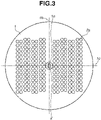
- the isotropically divided reflected light impinges on the reflective surface of the first reflecting portion 1, as illustrated in Fig. 3 .
- the first reflecting portion 1 light impinges at positions indicated by circles in Fig. 3 .
- the light fluxes resulting from the division by the second reflecting portion 2 are incident on each region into which the reflective surface of the first reflecting portion 1 are divided by two axes 1b and 1c perpendicular to a rotational symmetry axis of the first reflecting portion 1.
- the second reflecting portion 2 is arranged so that the center thereof is located on an optical axis passing through the opening or the transmitting portion 1a of the first reflecting portion 1.
- a plurality of mirrors (reflective surfaces) of the third reflecting portion 3 and the fourth reflecting portion 4 are arranged around a central axis with the optical axis of the first reflecting portion 1 serving as the central axis.
- the central axes of the first reflecting portion 1, the second reflecting portion 2, the third reflecting portion 3, and the fourth reflecting portion 4 are coaxially arranged.
- the third reflecting portion 3 is a mirror group including a plurality of mirrors (reflective surfaces) 3a, and reflects the light reflected by the second reflecting portion 2 and the first reflecting portion 1.
- the number of mirrors 3a of the third reflecting portion 3 on which the light from the first reflecting portion 1 is incident is the same as the number of divisions of the light fluxes by the second reflecting portion 2.
- the fourth reflecting portion 4 is a mirror group including a plurality of mirrors (reflective surfaces) 4a, and reflects the light from the third reflecting portion 3.
- the number of mirrors 4a of the fourth reflecting portion 4 on which the light from the first reflecting portion 1 is incident is the same as the number of mirrors 3a of the third reflecting portion 3.
- Each mirror 4a of the fourth reflecting portion 4 is a curved-surface mirror. Images that are condensed and one-dimensionally (linearly) arrayed by the mirrors 4a of the fourth reflecting portion 4 are formed in an image-reforming area. In other words, the light fluxes reflected by the first reflecting portion 1 are reflected by the third reflecting portion 3 and the fourth reflecting portion 4 to be image formed, so that divided images of the object plane is formed at an image-reforming position 5 of a predetermined plane.
- Each of the mirrors of the third reflecting portion 3 has a flat surface and each of the mirrors of the fourth reflecting portion 4 has a spherical surface, but may be reversed.
- either the plurality of mirrors of the third reflecting portion or the plurality of mirrors of the fourth reflecting portion has a flat surface and the other has a curved surface.
- each of the second reflecting portion 2, the third reflecting portion 3, and the fourth reflecting portion 4 face different directions.
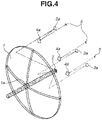
- Fig. 4 illustrates a bird's-eye view of the optical system 100, and illustrates optical paths reflected by the respective reflecting portions.
- the first reflecting portion 1 has an opening in a central portion, and the mirrors are arranged so that the light divided by the second reflecting portion 2 does not overlap the mirrors of each of the third reflecting portion 3 and the fourth reflecting portion 4.
- the second reflecting portion 2 is integrally molded so as to fill an image plane portion for the incident light.
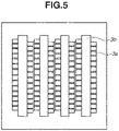
- Fig. 5 illustrates a configuration of the third reflecting portion.
- the mirrors 3a of the third reflecting portion 3 are each formed on a physically integrated structure, but an opening 3b is provided in a portion through which the light flux passes.
- the mirrors 4a of the fourth reflecting portion 4 is formed on a physically integrated structure, but an opening is provided in a portion through which the light flux passes.
- the first reflecting portion 1, the second reflecting portion 2, the third reflecting portion 3, and the fourth reflecting portion 4 have an isotropic structure centered on the incident light flux axis, and the plane spectroscopic optical system can be easily assembled, without any adjusting mechanism, by simply arranging these reflecting portions at desired intervals.
- the images are rearrayed using a space as densely as possible, and a flight distance in the space and the mirror configuration are also controlled, thus achieving downsizing and highly efficient plane division while providing high resolution.
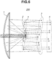
- FIG. 6 illustrates an optical system 200 according to the present exemplary embodiment.
- the fourth reflecting portion 4 is arranged forward of the second reflecting portion 2 (the side closer to a first reflecting portion).
- the fourth reflecting portion 4 is arranged in the vicinity of the front and rear of the second reflecting portion 2, and thus, the second reflecting portion 2 and the fourth reflecting portion 4 can be formed on an integrated structure.
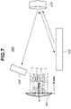
- Fig. 7 illustrates a schematic view of a plane spectroscopic device 500.
- the plane spectroscopic device 500 causes a light flux that is to be spectrally dispersed to be incident on an optical system 501 according to an above-described exemplary embodiment, one-dimensionally rearrays the light flux through plane division, and then performs the plane spectrum dispersion via an image-forming mirror 502, a spectroscopic element 503, and a detection unit 504.
- the light to be spectrally dispersed is, for example, infrared light.
- the light flux is reflected from the plane division optical system 501 to the spectroscopic element 503, which is, for example, a diffraction grating, using the image-forming mirror 502 which is an off-axis paraboloid mirror.
- the light flux spectrally dispersed by the spectroscopic element 503 and spread on the plane is incident on the paraboloid mirror again by diffraction, and forms an image on the detection unit 504 having a two-dimensional detector.
- a result of a spectrally dispersed image plane can be obtained.
- a plane spectroscopic device that is advantageous in downsizing, high resolution, or high efficiency can be provided.
Landscapes
- Physics & Mathematics (AREA)
- General Physics & Mathematics (AREA)
- Spectroscopy & Molecular Physics (AREA)
- Optics & Photonics (AREA)
- Biochemistry (AREA)
- Life Sciences & Earth Sciences (AREA)
- Chemical & Material Sciences (AREA)
- Analytical Chemistry (AREA)
- Health & Medical Sciences (AREA)
- General Health & Medical Sciences (AREA)
- Immunology (AREA)
- Pathology (AREA)
- Spectrometry And Color Measurement (AREA)
- Optical Elements Other Than Lenses (AREA)
- Lenses (AREA)
- Diffracting Gratings Or Hologram Optical Elements (AREA)
Abstract
Description
- The present exemplary embodiments relate to an optical system and a plane spectroscopic device.
- When a dynamic phenomenon is analyzed in detail, it is highly useful to obtain information about wavelength (energy) by simultaneously and temporally performing spectral dispersion on images, and it is important in all fields involving chemical reactions. To simultaneously perform spectral dispersion on image information, which is two-dimensional, it is necessary to convert a two-dimensional image into a one-dimensional image because a general detector supports two-dimensional or less dimensional images and thus the number of dimensions into which wavelength information is expanded increases. Thus, a plane division optical system is an important element in plane spectral division which is collectively performed at substantially the same timing (
Japanese Patent Application Laid-Open No. 2012-237647 - If an original image is more finely divided, higher-resolution information is obtainable, but it is not easy to one-dimensionally array divided images in a limited space. Most conveniently, one of means is to spread a large number of optical fibers all over an image portion and to one-dimensionally rearrange the optical fibers by utilizing their flexibility, which is a highly excellent method by which a higher resolution is achieved through an increase of fine optical fibers. However, the transmittance of the optical fiber is not completely uniform, and it is difficult to extract original light information in a uniform state, due to, for example, a polarization state of light changes because of a curvature. An optical fiber generally includes a core portion through which light passes and a clad portion that causes total reflection, and has an optimum size depending on a wavelength to be transmitted. Thus, there is no optical fiber optimum for a wide wavelength, and it is difficult in principle to efficiently perform plane spectral dispersion in a wide wavelength band. To address this, a method is available in which an image is spatially divided by a plurality of mirrors and the resultant image is one-dimensionally rearranged. There is a slight change in light characteristics due to reflection characteristics of the mirrors, but it is stable and it is easy to restore information. However, even if the divisional number is set to about several tens in consideration of manufacturing process, such as adjustment, because it is necessary to extremely accurately arrange the respective mirrors in terms of position and accuracy, the structure becomes spatially large, resulting in a difficulty in incorporating the mirrors into general equipment with an equivalent number of divisions. The plane division optical system is also effective in a case where an image is observed by a one-dimensional detector that is inexpensive and is capable of performing readout with high resolution at a high speed without using a two-dimensional detector.
- According to a first aspect of the present invention, there is provided an optical system as specified in
claims 1 to 7. According to a second aspect of the present invention, there is provided a plane spectroscopic device as specified in claims 8 to 9. - Further features of the present invention will become apparent from the following description of exemplary embodiments with reference to the attached drawings.
-
-
Fig. 1 is a view illustrating an optical system of a first exemplary embodiment. -
Figs. 2A to 2C are views each illustrating a configuration of a second reflecting portion. -
Fig. 3 is a view of the optical system according to the first exemplary embodiment as viewed from a side of a first reflecting portion. -
Fig. 4 is a bird's-eye view of the optical system according to the first exemplary embodiment. -
Fig. 5 is a view illustrating a configuration of a third reflecting portion. -
Fig. 6 is a view illustrating an optical system according to a second exemplary embodiment. -
Fig. 7 is a schematic view of a plane spectroscopic device. - Hereinafter, preferred exemplary embodiments of the present invention will be described in detail with reference to the accompanying drawings.
- A first exemplary embodiment of the present invention will be described below.
Fig. 1 illustrates a view of a field divisionoptical system 100 of the first exemplary embodiment. The field divisionoptical system 100 is an optical system that divides a light flux from a side of an object plane. As illustrated inFig. 1 , the field divisionoptical system 100 roughly includes four groups of mirrors in order from an incident direction of an incident light flux to be divided. The field divisionoptical system 100 includes a first reflectingportion 1, a second reflectingportion 2, a third reflectingportion 3, and a fourth reflectingportion 4. - The first reflecting
portion 1 is a curved-surface mirror having a curved reflective surface, and is provided with an opening through which the light flux from the object plane passes or a transmittingportion 1a through which the light flux is transmitted. For example, the opening is a cavity, and the transmittingportion 1a is formed of a transparent optical member. The first reflectingportion 1 is, for example, a rotationally symmetric concave mirror. - The second reflecting
portion 2 has a plurality of reflective surfaces (mirrors) 2a that reflects the light flux through the opening or the transmittingportion 1a of the first reflectingportion 1 in directions different from one another depending on positions. In other words, thereflective surfaces 2a divide incident light into light fluxes by reflecting the incident light to positions different from one another on the reflective surface of the first reflectingportion 1. The reflective surfaces of the second reflectingportion 2 are each a mirror having a rectangular outer shape and arranged without a gap on a plane on which the incident light forms an image. -
Figs. 2A to 2C each illustrate a configuration of the second reflecting portion. As illustrated inFig. 2A , the second reflectingportion 2 is supported by a support frame.Fig. 2B is a front view of the second reflectingportion 2, and the plurality ofreflective surfaces 2a is integrated as viewed from the front.Fig. 2C is a view of the second reflectingportion 2 as viewed obliquely, and the respective surfaces of the plurality ofreflective surfaces 2a face different directions from one another. - The incident light fluxes to be divided are all reflected in different directions by the respective
reflective surfaces 2a of the second reflectingportion 2, and are then reflected by the first reflectingportion 1. At this time, since each rectangularreflective surface 2a isotropically distributes the divided light, the isotropically divided reflected light impinges on the reflective surface of the first reflectingportion 1, as illustrated inFig. 3 . In the first reflectingportion 1, light impinges at positions indicated by circles inFig. 3 . In other words, the light fluxes resulting from the division by the second reflectingportion 2 are incident on each region into which the reflective surface of the first reflectingportion 1 are divided by twoaxes portion 1. - The second reflecting
portion 2 is arranged so that the center thereof is located on an optical axis passing through the opening or the transmittingportion 1a of the first reflectingportion 1. A plurality of mirrors (reflective surfaces) of the third reflectingportion 3 and the fourth reflectingportion 4 are arranged around a central axis with the optical axis of the first reflectingportion 1 serving as the central axis. In other words, the central axes of the first reflectingportion 1, the second reflectingportion 2, the third reflectingportion 3, and the fourth reflectingportion 4 are coaxially arranged. With such a configuration of theoptical system 100, it is possible to spatially utilize an isotropic space with the incident light flux as the axis, and to achieve downsizing. - The third reflecting
portion 3 is a mirror group including a plurality of mirrors (reflective surfaces) 3a, and reflects the light reflected by the second reflectingportion 2 and the first reflectingportion 1. The number ofmirrors 3a of the third reflectingportion 3 on which the light from the first reflectingportion 1 is incident is the same as the number of divisions of the light fluxes by the second reflectingportion 2. - The fourth reflecting
portion 4 is a mirror group including a plurality of mirrors (reflective surfaces) 4a, and reflects the light from the third reflectingportion 3. The number ofmirrors 4a of the fourth reflectingportion 4 on which the light from the first reflectingportion 1 is incident is the same as the number ofmirrors 3a of the third reflectingportion 3. Eachmirror 4a of the fourth reflectingportion 4 is a curved-surface mirror. Images that are condensed and one-dimensionally (linearly) arrayed by themirrors 4a of the fourth reflectingportion 4 are formed in an image-reforming area. In other words, the light fluxes reflected by the first reflectingportion 1 are reflected by the third reflectingportion 3 and the fourth reflectingportion 4 to be image formed, so that divided images of the object plane is formed at an image-reformingposition 5 of a predetermined plane. - Each of the mirrors of the third reflecting
portion 3 has a flat surface and each of the mirrors of the fourth reflectingportion 4 has a spherical surface, but may be reversed. In other words, either the plurality of mirrors of the third reflecting portion or the plurality of mirrors of the fourth reflecting portion has a flat surface and the other has a curved surface. - The mirrors of each of the second reflecting
portion 2, the third reflectingportion 3, and the fourth reflectingportion 4 face different directions. -
Fig. 4 illustrates a bird's-eye view of theoptical system 100, and illustrates optical paths reflected by the respective reflecting portions. The first reflectingportion 1 has an opening in a central portion, and the mirrors are arranged so that the light divided by the second reflectingportion 2 does not overlap the mirrors of each of the third reflectingportion 3 and the fourth reflectingportion 4. The second reflectingportion 2 is integrally molded so as to fill an image plane portion for the incident light. -
Fig. 5 illustrates a configuration of the third reflecting portion. Themirrors 3a of the third reflectingportion 3 are each formed on a physically integrated structure, but anopening 3b is provided in a portion through which the light flux passes. Similarly, themirrors 4a of the fourth reflectingportion 4 is formed on a physically integrated structure, but an opening is provided in a portion through which the light flux passes. - The first reflecting
portion 1, the second reflectingportion 2, the third reflectingportion 3, and the fourth reflectingportion 4 have an isotropic structure centered on the incident light flux axis, and the plane spectroscopic optical system can be easily assembled, without any adjusting mechanism, by simply arranging these reflecting portions at desired intervals. - As is clear from the light flux flight cross-sectional view of
Fig. 1 , the images are rearrayed using a space as densely as possible, and a flight distance in the space and the mirror configuration are also controlled, thus achieving downsizing and highly efficient plane division while providing high resolution. - A second exemplary embodiment of the present invention will be described below. In the present exemplary embodiment, relative positions of a second reflecting
portion 2 and a fourth reflectingportion 4 are different from those in the first exemplary embodiment.Fig. 6 illustrates anoptical system 200 according to the present exemplary embodiment. As illustrated inFig. 6 , the fourth reflectingportion 4 is arranged forward of the second reflecting portion 2 (the side closer to a first reflecting portion). As a result, the fourth reflectingportion 4 is arranged in the vicinity of the front and rear of the second reflectingportion 2, and thus, the second reflectingportion 2 and the fourth reflectingportion 4 can be formed on an integrated structure. - Next, a plane spectroscopic device using the optical system according to an above-described exemplary embodiment will be described.
-
Fig. 7 illustrates a schematic view of aplane spectroscopic device 500. Theplane spectroscopic device 500 causes a light flux that is to be spectrally dispersed to be incident on anoptical system 501 according to an above-described exemplary embodiment, one-dimensionally rearrays the light flux through plane division, and then performs the plane spectrum dispersion via an image-formingmirror 502, aspectroscopic element 503, and adetection unit 504. The light to be spectrally dispersed is, for example, infrared light. - In the
plane spectroscopic device 500, the light flux is reflected from the plane divisionoptical system 501 to thespectroscopic element 503, which is, for example, a diffraction grating, using the image-formingmirror 502 which is an off-axis paraboloid mirror. The light flux spectrally dispersed by thespectroscopic element 503 and spread on the plane is incident on the paraboloid mirror again by diffraction, and forms an image on thedetection unit 504 having a two-dimensional detector. Thus, a result of a spectrally dispersed image plane can be obtained. - To obtain an original image for each wavelength, it is possible to obtain a spectral image in an original-image form by rearraying a one-dimensional image of a desired wavelength on the two-dimensional detector in accordance with a division rule.
- Although the preferred exemplary embodiments of the present invention have been described above, the present invention is not limited to these exemplary embodiments, and various modifications and changes can be made within the scope of the gist of the present invention.
- According to the above exemplary embodiments, a plane spectroscopic device that is advantageous in downsizing, high resolution, or high efficiency can be provided.
- While the present invention has been described with reference to exemplary embodiments, it is to be understood that the invention is not limited to the disclosed exemplary embodiments. The scope of the following claims is to be accorded the broadest interpretation so as to encompass all such modifications and equivalent structures and functions.
Claims (9)
- An optical system that divides a light flux from an object plane, the optical system comprising:a first curved-surface mirror having an opening through which the light flux from the object plane passes or a transmitting portion through which the light flux is transmitted;a second reflecting portion including a plurality of reflective surfaces that divides the light flux from the opening or the transmitting portion of the first curved-surface mirror, and configured to reflect each of light fluxes resulting from the dividing by the respective reflective surfaces, to respective positions different from one another on the first curved-surface mirror;a third reflecting portion having a plurality of reflective surfaces each of which reflects the light fluxes that have resulted from the dividing by the second reflecting portion and have been reflected on the first curved-surface mirror; anda fourth reflecting portion having a plurality of reflective surfaces that reflects the light fluxes from the third reflecting portion,wherein the number of reflective surfaces of each of the third reflecting portion and the fourth reflecting portion on which the fluxes from the first curved-surface mirror are incident is the same as a division number in the dividing of the light flux by the second reflecting portion, andwherein the respective light fluxes reflected by the first curved-surface mirror are reflected by the third reflecting portion and the fourth reflecting portion to be image-formed so that divided images of the object plane are formed.
- The optical system according to claim 1, wherein central axes of the first curved-surface mirror, the second reflecting portion, the third reflecting portion, and the fourth reflecting portion are coaxially arranged.
- The optical system according to claim 1, wherein each reflective surface of the second reflecting portion has a rectangular shape.
- The optical system according to claim 1,wherein the first curved-surface mirror is a rotationally symmetric concave mirror, andwherein, in the first curved-surface mirror, the light fluxes resulting from the dividing by the second reflecting portion are incident on each of regions into which the first curved-surface mirror are divided by two axes perpendicular to a rotational symmetry axis.
- The optical system according to claim 1, wherein one of the plurality of reflective surfaces of the third reflecting portion and the plurality of reflective surfaces of the fourth reflecting portion is a flat surface, and the other is a curved surface.
- The optical system according to claim 1, wherein at least one of the second reflecting portion, the third reflecting portion, and the fourth reflecting portion integrally forms each reflective surface.
- The optical system according to claim 1, wherein each of the light fluxes reflected by the first curved-surface mirror is reflected by the third reflecting portion and the fourth reflecting portion to form an image in which divided images are each linearly arranged in a predetermined direction.
- A plane spectroscopic device comprising:an optical system according to claim 1;a spectroscopic element configured to spectrally disperse light from the optical system; anda detection means for detecting the light spectrally dispersed by the spectroscopic element.
- The plane spectroscopic device according to claim 8, wherein infrared light is spectrally dispersed.
Applications Claiming Priority (1)
| Application Number | Priority Date | Filing Date | Title |
|---|---|---|---|
| JP2020209578A JP2022096461A (en) | 2020-12-17 | 2020-12-17 | Optical system and surface spectroscopic apparatus |
Publications (1)
| Publication Number | Publication Date |
|---|---|
| EP4016016A1 true EP4016016A1 (en) | 2022-06-22 |
Family
ID=78827839
Family Applications (1)
| Application Number | Title | Priority Date | Filing Date |
|---|---|---|---|
| EP21213503.2A Pending EP4016016A1 (en) | 2020-12-17 | 2021-12-09 | Optical system and plane spectroscopic device |
Country Status (4)
| Country | Link |
|---|---|
| US (1) | US11880025B2 (en) |
| EP (1) | EP4016016A1 (en) |
| JP (2) | JP2022096461A (en) |
| CN (1) | CN114647073B (en) |
Citations (2)
| Publication number | Priority date | Publication date | Assignee | Title |
|---|---|---|---|---|
| US20060072109A1 (en) * | 2004-09-03 | 2006-04-06 | Andrew Bodkin | Hyperspectral imaging systems |
| JP2012237647A (en) | 2011-05-11 | 2012-12-06 | Univ Of Tokyo | Multifocal confocal raman spectroscopic microscope |
Family Cites Families (22)
| Publication number | Priority date | Publication date | Assignee | Title |
|---|---|---|---|---|
| JPS5136090B1 (en) * | 1971-04-17 | 1976-10-06 | ||
| JPH0782117B2 (en) * | 1989-02-23 | 1995-09-06 | オリンパス光学工業株式会社 | Reflective imaging optics |
| JPH03189602A (en) * | 1989-12-20 | 1991-08-19 | Nippon Telegr & Teleph Corp <Ntt> | Light beam controller |
| US20040057049A1 (en) * | 2002-09-20 | 2004-03-25 | Applied Photonics Worldwide, Inc. | Micromechanical monochromator with integrated slit aperture for microspectrometers in the UV, visible and infrared range |
| JP4287794B2 (en) * | 2004-06-30 | 2009-07-01 | 株式会社フォトロン | Multi-screen spectroscopic device |
| JP2006350023A (en) * | 2005-06-16 | 2006-12-28 | Fujitsu Ltd | Variable dispersion compensator |
| JP4839845B2 (en) * | 2006-01-13 | 2011-12-21 | 横河電機株式会社 | Spectrometer |
| JP2009000708A (en) * | 2007-06-20 | 2009-01-08 | Nikon Corp | Light irradiation apparatus and laser processing apparatus including the same |
| EP2203787B1 (en) * | 2007-10-26 | 2014-05-14 | Carl Zeiss SMT GmbH | Imaging optical system and projection exposure installation for micro-lithography with an imaging optical system of this type |
| JP2009141154A (en) * | 2007-12-06 | 2009-06-25 | Canon Inc | Scanning exposure apparatus and device manufacturing method |
| JP2010008487A (en) * | 2008-06-24 | 2010-01-14 | Fujitsu Ltd | Optical module and dispersion compensator |
| TWI408356B (en) * | 2008-09-02 | 2013-09-11 | Ind Tech Res Inst | Reflective scatterometer |
| JP5483955B2 (en) * | 2009-08-20 | 2014-05-07 | キヤノン株式会社 | Illumination optical system and projection display device |
| US9529083B2 (en) * | 2009-11-20 | 2016-12-27 | Faro Technologies, Inc. | Three-dimensional scanner with enhanced spectroscopic energy detector |
| JP5335729B2 (en) * | 2010-04-01 | 2013-11-06 | 浜松ホトニクス株式会社 | Spectroscopic module |
| JP2012098050A (en) * | 2010-10-29 | 2012-05-24 | Mitaka Koki Co Ltd | Monitorable spectrometer |
| TWI642507B (en) * | 2011-12-16 | 2018-12-01 | 應用材料股份有限公司 | Radiation source and multiple beam combiner for laser processing apparatus |
| KR102491749B1 (en) * | 2015-03-01 | 2023-01-25 | 아카이브 코퍼레이션 | Panoramic 3D Imaging System |
| JP6317050B1 (en) * | 2016-06-17 | 2018-04-25 | オリンパス株式会社 | Objective optical system and endoscope apparatus including the same |
| US10185133B1 (en) * | 2017-09-15 | 2019-01-22 | Raytheon Company | Reflective triplet foreoptics for multi-channel double-pass dispersive spectrometers |
| JP7239582B2 (en) * | 2017-11-30 | 2023-03-14 | アジレント・テクノロジーズ・インク | Polychromator system and method |
| CN110989182A (en) * | 2019-11-29 | 2020-04-10 | 中国科学院长春光学精密机械与物理研究所 | A beam combining light source device |
-
2020
- 2020-12-17 JP JP2020209578A patent/JP2022096461A/en active Pending
-
2021
- 2021-12-09 EP EP21213503.2A patent/EP4016016A1/en active Pending
- 2021-12-09 US US17/547,023 patent/US11880025B2/en active Active
- 2021-12-14 CN CN202111525655.7A patent/CN114647073B/en active Active
-
2025
- 2025-03-14 JP JP2025041446A patent/JP2025083525A/en active Pending
Patent Citations (2)
| Publication number | Priority date | Publication date | Assignee | Title |
|---|---|---|---|---|
| US20060072109A1 (en) * | 2004-09-03 | 2006-04-06 | Andrew Bodkin | Hyperspectral imaging systems |
| JP2012237647A (en) | 2011-05-11 | 2012-12-06 | Univ Of Tokyo | Multifocal confocal raman spectroscopic microscope |
Non-Patent Citations (3)
| Title |
|---|
| CONTENT ROBERT: "Image slicer for integral field spectroscopy with NGST", ALGORITHMS AND TECHNOLOGIES FOR MULTISPECTRAL, HYPERSPECTRAL, AND ULTRASPECTRAL IMAGERY XIX - PROCEEDINGS OF SPIE, vol. 3356, 28 August 1998 (1998-08-28), US, pages 122 - 133, XP055914169, ISSN: 0277-786X, ISBN: 978-1-5106-4548-6, DOI: 10.1117/12.324521 * |
| DING XIAOMING ET AL: "Modeling and Optimization of Image Mapper for Snapshot Image Mapping Spectrometer", IEEE ACCESS, vol. 6, 8 May 2018 (2018-05-08), pages 29344 - 29352, XP011685581, DOI: 10.1109/ACCESS.2018.2834485 * |
| HAGEN NATHAN ET AL: "Review of snapshot spectral imaging technologies", OPTICAL ENGINEERING, vol. 52, no. 9, 23 September 2013 (2013-09-23), BELLINGHAM, pages 090901, XP055915445, ISSN: 0091-3286, DOI: 10.1117/1.OE.52.9.090901 * |
Also Published As
| Publication number | Publication date |
|---|---|
| US20220196997A1 (en) | 2022-06-23 |
| JP2022096461A (en) | 2022-06-29 |
| CN114647073A (en) | 2022-06-21 |
| US11880025B2 (en) | 2024-01-23 |
| CN114647073B (en) | 2025-06-13 |
| JP2025083525A (en) | 2025-05-30 |
Similar Documents
| Publication | Publication Date | Title |
|---|---|---|
| US4984888A (en) | Two-dimensional spectrometer | |
| US5260767A (en) | Compact all-reflective imaging spectrometer | |
| US6108471A (en) | Compact double-pass wavelength multiplexer-demultiplexer having an increased number of channels | |
| US5420681A (en) | Modular multiple spectral imager and spectral imager | |
| US5463498A (en) | Internally cooled large aperture microlens array with monolithically integrated microscanner | |
| US5768040A (en) | Wide field-of-view imaging spectrometer | |
| EP0274531B1 (en) | Imaging spectrometer | |
| US4650279A (en) | Fiber optic lens | |
| JPH08240793A (en) | Refractive ellipsoidal optical surface without spherical aberration | |
| CN109844560B (en) | Optical components for lidar systems | |
| CN105547478B (en) | Imaging spectrometer based on etched diffraction grating | |
| US20260009676A1 (en) | Optical component and system for simultaneous 3d hyperspectral imaging | |
| CN205537958U (en) | Imaging spectrometer based on etching diffraction grating | |
| US20230314218A1 (en) | Metasurface-based spectrometer and electronic device | |
| US12242077B1 (en) | Wide spatial field optical systems | |
| US11880025B2 (en) | Optical system and plane spectroscopic device | |
| Tecza et al. | SPIFFI image slicer: revival of image slicing with plane mirrors | |
| Hill et al. | VIRUS: a massively replicated integral-field spectrograph for HET | |
| US20250216257A1 (en) | Optical component and system for simultaneous 3d hyperspectral imaging | |
| Chen et al. | Gemini IRMOS: preliminary optical design of a multi-object adaptive optics-fed infrared integral-field spectrograph | |
| US4718764A (en) | Frequency agile spectrometer | |
| US5353155A (en) | Methods and apparatus for combining arrays of light beams | |
| Content | Image slicer for integral field spectroscopy with NGST | |
| CN220871902U (en) | A dual-channel seamless spectrometer | |
| CN115342917B (en) | A compact large-field-of-view spectral imaging system based on sub-field-of-view stitching |
Legal Events
| Date | Code | Title | Description |
|---|---|---|---|
| PUAI | Public reference made under article 153(3) epc to a published international application that has entered the european phase |
Free format text: ORIGINAL CODE: 0009012 |
|
| STAA | Information on the status of an ep patent application or granted ep patent |
Free format text: STATUS: THE APPLICATION HAS BEEN PUBLISHED |
|
| AK | Designated contracting states |
Kind code of ref document: A1 Designated state(s): AL AT BE BG CH CY CZ DE DK EE ES FI FR GB GR HR HU IE IS IT LI LT LU LV MC MK MT NL NO PL PT RO RS SE SI SK SM TR |
|
| STAA | Information on the status of an ep patent application or granted ep patent |
Free format text: STATUS: REQUEST FOR EXAMINATION WAS MADE |
|
| 17P | Request for examination filed |
Effective date: 20221222 |
|
| RBV | Designated contracting states (corrected) |
Designated state(s): AL AT BE BG CH CY CZ DE DK EE ES FI FR GB GR HR HU IE IS IT LI LT LU LV MC MK MT NL NO PL PT RO RS SE SI SK SM TR |
|
| STAA | Information on the status of an ep patent application or granted ep patent |
Free format text: STATUS: EXAMINATION IS IN PROGRESS |
|
| 17Q | First examination report despatched |
Effective date: 20240910 |