EP4015973A1 - Extraplanetary heat exchanger - Google Patents
Extraplanetary heat exchanger Download PDFInfo
- Publication number
- EP4015973A1 EP4015973A1 EP21214896.9A EP21214896A EP4015973A1 EP 4015973 A1 EP4015973 A1 EP 4015973A1 EP 21214896 A EP21214896 A EP 21214896A EP 4015973 A1 EP4015973 A1 EP 4015973A1
- Authority
- EP
- European Patent Office
- Prior art keywords
- heat exchanger
- habitat
- fluid
- flow
- pathway
- Prior art date
- Legal status (The legal status is an assumption and is not a legal conclusion. Google has not performed a legal analysis and makes no representation as to the accuracy of the status listed.)
- Granted
Links
Images

Classifications
-
- F—MECHANICAL ENGINEERING; LIGHTING; HEATING; WEAPONS; BLASTING
- F28—HEAT EXCHANGE IN GENERAL
- F28F—DETAILS OF HEAT-EXCHANGE AND HEAT-TRANSFER APPARATUS, OF GENERAL APPLICATION
- F28F3/00—Plate-like or laminated elements; Assemblies of plate-like or laminated elements
- F28F3/12—Elements constructed in the shape of a hollow panel, e.g. with channels
-
- F—MECHANICAL ENGINEERING; LIGHTING; HEATING; WEAPONS; BLASTING
- F24—HEATING; RANGES; VENTILATING
- F24T—GEOTHERMAL COLLECTORS; GEOTHERMAL SYSTEMS
- F24T10/00—Geothermal collectors
- F24T10/10—Geothermal collectors with circulation of working fluids through underground channels, the working fluids not coming into direct contact with the ground
-
- B—PERFORMING OPERATIONS; TRANSPORTING
- B64—AIRCRAFT; AVIATION; COSMONAUTICS
- B64G—COSMONAUTICS; VEHICLES OR EQUIPMENT THEREFOR
- B64G99/00—Subject matter not provided for in other groups of this subclass
-
- E—FIXED CONSTRUCTIONS
- E04—BUILDING
- E04B—GENERAL BUILDING CONSTRUCTIONS; WALLS, e.g. PARTITIONS; ROOFS; FLOORS; CEILINGS; INSULATION OR OTHER PROTECTION OF BUILDINGS
- E04B1/00—Constructions in general; Structures which are not restricted either to walls, e.g. partitions, or floors or ceilings or roofs
- E04B1/34—Extraordinary structures, e.g. with suspended or cantilever parts supported by masts or tower-like structures enclosing elevators or stairs; Features relating to the elastic stability
-
- F—MECHANICAL ENGINEERING; LIGHTING; HEATING; WEAPONS; BLASTING
- F24—HEATING; RANGES; VENTILATING
- F24F—AIR-CONDITIONING; AIR-HUMIDIFICATION; VENTILATION; USE OF AIR CURRENTS FOR SCREENING
- F24F13/00—Details common to, or for air-conditioning, air-humidification, ventilation or use of air currents for screening
- F24F13/30—Arrangement or mounting of heat-exchangers
-
- F—MECHANICAL ENGINEERING; LIGHTING; HEATING; WEAPONS; BLASTING
- F24—HEATING; RANGES; VENTILATING
- F24F—AIR-CONDITIONING; AIR-HUMIDIFICATION; VENTILATION; USE OF AIR CURRENTS FOR SCREENING
- F24F5/00—Air-conditioning systems or apparatus not covered by F24F1/00 or F24F3/00, e.g. using solar heat or combined with household units such as an oven or water heater
- F24F5/0046—Air-conditioning systems or apparatus not covered by F24F1/00 or F24F3/00, e.g. using solar heat or combined with household units such as an oven or water heater using natural energy, e.g. solar energy, energy from the ground
-
- F—MECHANICAL ENGINEERING; LIGHTING; HEATING; WEAPONS; BLASTING
- F28—HEAT EXCHANGE IN GENERAL
- F28F—DETAILS OF HEAT-EXCHANGE AND HEAT-TRANSFER APPARATUS, OF GENERAL APPLICATION
- F28F1/00—Tubular elements; Assemblies of tubular elements
- F28F1/10—Tubular elements and assemblies thereof with means for increasing heat-transfer area, e.g. with fins, with projections, with recesses
- F28F1/12—Tubular elements and assemblies thereof with means for increasing heat-transfer area, e.g. with fins, with projections, with recesses the means being only outside the tubular element
-
- F—MECHANICAL ENGINEERING; LIGHTING; HEATING; WEAPONS; BLASTING
- F28—HEAT EXCHANGE IN GENERAL
- F28F—DETAILS OF HEAT-EXCHANGE AND HEAT-TRANSFER APPARATUS, OF GENERAL APPLICATION
- F28F7/00—Elements not covered by group F28F1/00, F28F3/00 or F28F5/00
- F28F7/02—Blocks traversed by passages for heat-exchange media
-
- F—MECHANICAL ENGINEERING; LIGHTING; HEATING; WEAPONS; BLASTING
- F28—HEAT EXCHANGE IN GENERAL
- F28D—HEAT-EXCHANGE APPARATUS, NOT PROVIDED FOR IN ANOTHER SUBCLASS, IN WHICH THE HEAT-EXCHANGE MEDIA DO NOT COME INTO DIRECT CONTACT
- F28D21/00—Heat-exchange apparatus not covered by any of the groups F28D1/00 - F28D20/00
- F28D2021/0019—Other heat exchangers for particular applications; Heat exchange systems not otherwise provided for
- F28D2021/0021—Other heat exchangers for particular applications; Heat exchange systems not otherwise provided for for aircrafts or cosmonautics
-
- F—MECHANICAL ENGINEERING; LIGHTING; HEATING; WEAPONS; BLASTING
- F28—HEAT EXCHANGE IN GENERAL
- F28F—DETAILS OF HEAT-EXCHANGE AND HEAT-TRANSFER APPARATUS, OF GENERAL APPLICATION
- F28F2255/00—Heat exchanger elements made of materials having special features or resulting from particular manufacturing processes
- F28F2255/14—Heat exchanger elements made of materials having special features or resulting from particular manufacturing processes molded
- F28F2255/146—Heat exchanger elements made of materials having special features or resulting from particular manufacturing processes molded overmolded
-
- Y—GENERAL TAGGING OF NEW TECHNOLOGICAL DEVELOPMENTS; GENERAL TAGGING OF CROSS-SECTIONAL TECHNOLOGIES SPANNING OVER SEVERAL SECTIONS OF THE IPC; TECHNICAL SUBJECTS COVERED BY FORMER USPC CROSS-REFERENCE ART COLLECTIONS [XRACs] AND DIGESTS
- Y02—TECHNOLOGIES OR APPLICATIONS FOR MITIGATION OR ADAPTATION AGAINST CLIMATE CHANGE
- Y02B—CLIMATE CHANGE MITIGATION TECHNOLOGIES RELATED TO BUILDINGS, e.g. HOUSING, HOUSE APPLIANCES OR RELATED END-USER APPLICATIONS
- Y02B10/00—Integration of renewable energy sources in buildings
- Y02B10/40—Geothermal heat-pumps
-
- Y—GENERAL TAGGING OF NEW TECHNOLOGICAL DEVELOPMENTS; GENERAL TAGGING OF CROSS-SECTIONAL TECHNOLOGIES SPANNING OVER SEVERAL SECTIONS OF THE IPC; TECHNICAL SUBJECTS COVERED BY FORMER USPC CROSS-REFERENCE ART COLLECTIONS [XRACs] AND DIGESTS
- Y02—TECHNOLOGIES OR APPLICATIONS FOR MITIGATION OR ADAPTATION AGAINST CLIMATE CHANGE
- Y02E—REDUCTION OF GREENHOUSE GAS [GHG] EMISSIONS, RELATED TO ENERGY GENERATION, TRANSMISSION OR DISTRIBUTION
- Y02E10/00—Energy generation through renewable energy sources
- Y02E10/10—Geothermal energy
Definitions
- Exemplary embodiments pertain to the art of extraplanetary habitats, and in particular to heat dissipation from an extraplanetary habitat and/or equipment.
- Atmosphere air
- a thermal energy exchange apparatus must be provided.
- an extraplanetary habitat system includes a habitat located on a site including a layer of regolith material and one or more heat-generating systems located in the habitat.
- a ⁇ Y ⁇ is operably connected to the habitat.
- the heat exchanger is located beneath the layer of regolith material and is configured to conduct the heat from the habitat into the layer of regolith material.
- an input pathway connects the one or more heat generating systems to the heat exchanger, to direct a flow of fluid from the habitat to the heat exchanger
- an output pathway connects the habitat to the heat exchanger to direct the flow of fluid cooled by the heat exchanger to the habitat.
- the flow of fluid is one of air, water or refrigerant.
- a pump or a fan is operably connected to one or more of the input pathway or the output pathway to urge the flow of fluid therethrough.
- the heat exchanger includes a heat exchanger pathway through which the flow of fluid is directed to exchange thermal energy with the regolith material.
- the heat exchanger pathway is multi-pass.
- a plurality of fins extend from the heat exchanger pathway.
- the heat exchanger is located at a depth of between 1 and 3 feet below a top surface of the regolith material.
- the one or more heat generating systems includes an environmental control and life support system or a thermal control system.
- a method of cooling one or more heat generating components of an extraplanetary habitat includes directing a flow of fluid from the habitat to a heat exchanger located beneath a layer of regolith material, exchanging thermal energy between the flow of fluid and the regolith material, thereby cooling the volume of fluid, and directing the flow of fluid from the heat exchanger to the habitat, thus cooling the habitat.
- the fluid is flowed from the habitat to the heat exchanger along an input pathway connecting the habitat to the heat exchanger, and the fluid is flowed from the heat exchanger to the habitat along an output pathway connecting the habitat to the heat exchanger.
- the flow of fluid is one of air, water or refrigerant.
- one of a pump or a fan is operably connected to one or more of the input pathway or the output pathway.
- the heat exchanger includes a heat exchanger pathway through which the flow of fluid is directed to exchanger thermal energy with the regolith material.
- the heat exchanger pathway is multipass.
- a plurality of fins extend from the heat exchanger pathway.
- the heat exchanger is located at a depth of between 1 and 3 feet below a top surface of the regolith material.
- the one or more heat generating systems includes an environmental control and life support system or a thermal control system.
- the habitat 10 is located over a site 12 comprising a layer of regolith material 14.
- the site 12 is, for example, an extraterrestrial location, such as a moon, an asteroid or another planet.
- the habitat 10 includes one or more devices that generate heat and which are desired to be cooled.
- the habitat 10 may include an environmental control and life support system (ECLSS) and/or a thermal control system or other components such as electronics or the like which generate heat through operation.
- ELSS environmental control and life support system
- thermal control system or other components such as electronics or the like which generate heat through operation.
- a heat exchanger 18 is connected to the habitat 10 to dissipate thermal energy from the habitat 10.
- the heat exchanger 18 is buried in the regolith material 14 and utilizes the thermal conductivity of the regolith material 14 to a working fluid circulated through the heat exchanger 18 in thermal energy dissipation.
- the regolith material 14 is especially useful in extraterrestrial environments such as the moon, as a gaseous atmosphere cannot be utilized there as a heat dissipator.
- the habitat 10 is connected to the heat exchanger 18 via an input pathway 20 and connected to the heat exchanger 18 at a heat exchanger inlet 22 and an output pathway 24 connected to the heat exchanger 18 at a heat exchanger outlet 26.
- the input pathway 20 and the output pathway 24 may be, for example, pipes, hoses or other conduits for conveying the working fluid between the heat exchanger 18 and the habitat 10.
- relatively warm working fluid 28, for example, air, water, refrigerant, or other fluids is circulated from the habitat 10 to the heat exchanger 18 via the input pathway 20 and through the heat exchanger 18.
- thermal energy from the working fluid 28 is transferred to the regolith material 14 via conduction of the regolith material 14, thus cooling the working fluid 28.
- the cooled working fluid 28 is then returned to the habitat 10 via the output pathway 24.
- a pump 44, or alternatively a fan, located, for example, along the input pathway 20 or the output pathway 24 is utilized to urge the working fluid 28 flow through the heat exchanger 18.
- the heat exchanger 18 is a conduit 32 located in a trench 30 or hole formed in the regolith material 14, which, after installation of the heat exchanger 18, is refilled with regolith material 14.
- the heat exchanger 18 is a single-pass heat exchanger 18.
- the heat exchanger conduit 32 may have a multi-pass configuration.
- the heat exchanger conduit 32 is formed from a thermally conductive material such as copper or aluminum, which may need to be coated or alloyed to prevent galvanic corrosion, or plastic or composite materials.
- the heat exchanger 18 has a spiral or coiled configuration.
- the could configuration is formed by wrapping or winding of a flexible material, or in other embodiments by additive manufacturing or other suitable processes.
- Such materials may include, for example, a metal-impregnated polymer or the like.
- the heat exchanger 18 includes one or more fins 34 or other features extending from the heat exchanger conduit 32 to aid in conducting thermal energy from the working fluid 28 into the regolith material 14.
- the fins 34 and the heat exchanger conduit 32 are formed from the same thermally conductive material as the conduit 32, while in other embodiments the fins 34 and the heat exchanger conduit 32 are formed from different materials.
- the trench 30 is formed in the regolith material 14 at a depth 36 (shown in FIG. 1 ) to maximize thermal conductivity from the heat exchanger 18, while also minimizing the necessary depth for installation.
- the depth 36 is in the range of 1 to 3 feet.
- a trench 30 is not utilized.
- the heat exchanger 18 is placed on the surface of the site 12, and a mound 38 of regolith material 14 is formed around and over the heat exchanger 18.
- the regolith material 14 around and atop the heat exchanger 18 has a thickness 40 in the range of 1 to 3 feet.
- the thickness 40 needed or utilized is temperature dependent, and other thicknesses may be utilized to achieve the desired thermal energy transfer.
- the shape of the mound 38 is not limited by the exemplary shape shown in FIG. 6 .
- regolith material 14 as a medium into which thermal energy generated by the ELCSS and/or other components of the habitat 10 is dissipated is effective and cost efficient, without requiring the use of more complex systems to reject the thermal energy.
Landscapes
- Engineering & Computer Science (AREA)
- Mechanical Engineering (AREA)
- General Engineering & Computer Science (AREA)
- Physics & Mathematics (AREA)
- Chemical & Material Sciences (AREA)
- Combustion & Propulsion (AREA)
- Life Sciences & Earth Sciences (AREA)
- Thermal Sciences (AREA)
- Architecture (AREA)
- Sustainable Development (AREA)
- Sustainable Energy (AREA)
- Electromagnetism (AREA)
- Civil Engineering (AREA)
- Structural Engineering (AREA)
- Aviation & Aerospace Engineering (AREA)
- Geometry (AREA)
- Remote Sensing (AREA)
- Heat-Exchange Devices With Radiators And Conduit Assemblies (AREA)
- Other Air-Conditioning Systems (AREA)
Abstract
Description
- Exemplary embodiments pertain to the art of extraplanetary habitats, and in particular to heat dissipation from an extraplanetary habitat and/or equipment.
- In extraplanetary environments, such as locations on the moon, Mars, or the like, heat is generated by equipment such as electronics which must be dissipated, and/or it is desired to provide climate control to a habitat. Atmosphere (air) may be thin or non-existent, so traditional methods of heat transfer cannot be utilized. Thus, a thermal energy exchange apparatus must be provided.
- In one embodiment, an extraplanetary habitat system includes a habitat located on a site including a layer of regolith material and one or more heat-generating systems located in the habitat. A <Y< is operably connected to the habitat. The heat exchanger is located beneath the layer of regolith material and is configured to conduct the heat from the habitat into the layer of regolith material.
- Additionally or alternatively, in this or other embodiments an input pathway connects the one or more heat generating systems to the heat exchanger, to direct a flow of fluid from the habitat to the heat exchanger, an output pathway connects the habitat to the heat exchanger to direct the flow of fluid cooled by the heat exchanger to the habitat.
- Additionally or alternatively, in this or other embodiments the flow of fluid is one of air, water or refrigerant.
- Additionally or alternatively, in this or other embodiments a pump or a fan is operably connected to one or more of the input pathway or the output pathway to urge the flow of fluid therethrough.
- Additionally or alternatively, in this or other embodiments the heat exchanger includes a heat exchanger pathway through which the flow of fluid is directed to exchange thermal energy with the regolith material.
- Additionally or alternatively, in this or other embodiments the heat exchanger pathway is multi-pass.
- Additionally or alternatively, in this or other embodiments a plurality of fins extend from the heat exchanger pathway.
- Additionally or alternatively, in this or other embodiments the heat exchanger is located at a depth of between 1 and 3 feet below a top surface of the regolith material.
- Additionally or alternatively, in this or other embodiments the one or more heat generating systems includes an environmental control and life support system or a thermal control system.
- In another embodiment, a method of cooling one or more heat generating components of an extraplanetary habitat includes directing a flow of fluid from the habitat to a heat exchanger located beneath a layer of regolith material, exchanging thermal energy between the flow of fluid and the regolith material, thereby cooling the volume of fluid, and directing the flow of fluid from the heat exchanger to the habitat, thus cooling the habitat.
- Additionally or alternatively, in this or other embodiments the fluid is flowed from the habitat to the heat exchanger along an input pathway connecting the habitat to the heat exchanger, and the fluid is flowed from the heat exchanger to the habitat along an output pathway connecting the habitat to the heat exchanger.
- Additionally or alternatively, in this or other embodiments the flow of fluid is one of air, water or refrigerant.
- Additionally or alternatively, in this or other embodiments one of a pump or a fan is operably connected to one or more of the input pathway or the output pathway.
- Additionally or alternatively, in this or other embodiments the heat exchanger includes a heat exchanger pathway through which the flow of fluid is directed to exchanger thermal energy with the regolith material.
- Additionally or alternatively, in this or other embodiments the heat exchanger pathway is multipass.
- Additionally or alternatively, in this or other embodiments a plurality of fins extend from the heat exchanger pathway.
- Additionally or alternatively, in this or other embodiments the heat exchanger is located at a depth of between 1 and 3 feet below a top surface of the regolith material.
- Additionally or alternatively, in this or other embodiments the one or more heat generating systems includes an environmental control and life support system or a thermal control system.
- The following descriptions should not be considered limiting in any way. With reference to the accompanying drawings, like elements are numbered alike:
-
FIG. 1 is a schematic view of an embodiment of an extraplanetary habitat having a heat exchanger; -
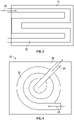
FIG. 2 is a plan view of an embodiment of a heat exchanger; -
FIG. 3 is a plan view of another embodiment of a heat exchanger; -
FIG. 4 is another plan view of an embodiment of a heat exchanger; -
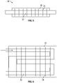
FIG. 5 is yet another plan view of an embodiment of a heat exchanger; and -
FIG. 6 is a schematic view of yet another embodiment of a heat exchanger; and -
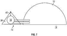
FIG. 7 is a schematic view of another embodiment of an extraplanetary habitat having a heat exchanger. - A detailed description of one or more embodiments of the disclosed apparatus and method are presented herein by way of exemplification and not limitation with reference to the Figures.
- Referring now to
FIG. 1 , illustrated is a schematic view of anextraplanetary habitat 10. Thehabitat 10 is located over asite 12 comprising a layer ofregolith material 14. Thesite 12 is, for example, an extraterrestrial location, such as a moon, an asteroid or another planet. Thehabitat 10 includes one or more devices that generate heat and which are desired to be cooled. For example, thehabitat 10 may include an environmental control and life support system (ECLSS) and/or a thermal control system or other components such as electronics or the like which generate heat through operation. - A
heat exchanger 18 is connected to thehabitat 10 to dissipate thermal energy from thehabitat 10. Theheat exchanger 18 is buried in theregolith material 14 and utilizes the thermal conductivity of theregolith material 14 to a working fluid circulated through theheat exchanger 18 in thermal energy dissipation. Theregolith material 14 is especially useful in extraterrestrial environments such as the moon, as a gaseous atmosphere cannot be utilized there as a heat dissipator. Thehabitat 10 is connected to theheat exchanger 18 via an input pathway 20 and connected to theheat exchanger 18 at a heat exchanger inlet 22 and anoutput pathway 24 connected to theheat exchanger 18 at aheat exchanger outlet 26. The input pathway 20 and theoutput pathway 24 may be, for example, pipes, hoses or other conduits for conveying the working fluid between theheat exchanger 18 and thehabitat 10. - In operation, relatively
warm working fluid 28, for example, air, water, refrigerant, or other fluids is circulated from thehabitat 10 to theheat exchanger 18 via the input pathway 20 and through theheat exchanger 18. At the heat exchanger, 18, thermal energy from the workingfluid 28 is transferred to theregolith material 14 via conduction of theregolith material 14, thus cooling the workingfluid 28. The cooled workingfluid 28 is then returned to thehabitat 10 via theoutput pathway 24. In some embodiments, apump 44, or alternatively a fan, located, for example, along the input pathway 20 or theoutput pathway 24 is utilized to urge the workingfluid 28 flow through theheat exchanger 18. - Referring now to
FIG. 2 , illustrated is an embodiment of aheat exchanger 18. In the embodiment illustrated, theheat exchanger 18 is aconduit 32 located in atrench 30 or hole formed in theregolith material 14, which, after installation of theheat exchanger 18, is refilled withregolith material 14. In the illustrated embodiment, theheat exchanger 18 is a single-pass heat exchanger 18. Alternatively, as illustrated inFIG. 3 theheat exchanger conduit 32 may have a multi-pass configuration. Theheat exchanger conduit 32 is formed from a thermally conductive material such as copper or aluminum, which may need to be coated or alloyed to prevent galvanic corrosion, or plastic or composite materials. In another embodiment, shown inFIG. 4 , theheat exchanger 18 has a spiral or coiled configuration. In some embodiments, the could configuration is formed by wrapping or winding of a flexible material, or in other embodiments by additive manufacturing or other suitable processes. Such materials may include, for example, a metal-impregnated polymer or the like. - As shown in
FIGs. 5 and 6 , in some embodiments, theheat exchanger 18 includes one ormore fins 34 or other features extending from theheat exchanger conduit 32 to aid in conducting thermal energy from the workingfluid 28 into theregolith material 14. In some embodiments, thefins 34 and theheat exchanger conduit 32 are formed from the same thermally conductive material as theconduit 32, while in other embodiments thefins 34 and theheat exchanger conduit 32 are formed from different materials. - The
trench 30 is formed in theregolith material 14 at a depth 36 (shown inFIG. 1 ) to maximize thermal conductivity from theheat exchanger 18, while also minimizing the necessary depth for installation. In some embodiments (e.g. on the moon), thedepth 36 is in the range of 1 to 3 feet. - Alternatively, in other embodiments, such as shown in
FIG. 7 atrench 30 is not utilized. Theheat exchanger 18 is placed on the surface of thesite 12, and amound 38 ofregolith material 14 is formed around and over theheat exchanger 18. In some embodiments, theregolith material 14 around and atop theheat exchanger 18 has athickness 40 in the range of 1 to 3 feet. Thethickness 40 needed or utilized is temperature dependent, and other thicknesses may be utilized to achieve the desired thermal energy transfer. The shape of themound 38 is not limited by the exemplary shape shown inFIG. 6 . - Use of the
regolith material 14 as a medium into which thermal energy generated by the ELCSS and/or other components of thehabitat 10 is dissipated is effective and cost efficient, without requiring the use of more complex systems to reject the thermal energy. - The term "about" is intended to include the degree of error associated with measurement of the particular quantity based upon the equipment available at the time of filing the application.
- The terminology used herein is for the purpose of describing particular embodiments only and is not intended to be limiting of the present disclosure. As used herein, the singular forms "a", "an" and "the" are intended to include the plural forms as well, unless the context clearly indicates otherwise. It will be further understood that the terms "comprises" and/or "comprising," when used in this specification, specify the presence of stated features, integers, steps, operations, elements, and/or components, but do not preclude the presence or addition of one or more other features, integers, steps, operations, element components, and/or groups thereof.
- While the present disclosure has been described with reference to an exemplary embodiment or embodiments, it will be understood by those skilled in the art that various changes may be made and equivalents may be substituted for elements thereof without departing from the scope of the present disclosure. In addition, many modifications may be made to adapt a particular situation or material to the teachings of the present disclosure without departing from the essential scope thereof. Therefore, it is intended that the present disclosure not be limited to the particular embodiment disclosed as the best mode contemplated for carrying out this present disclosure, but that the present disclosure will include all embodiments falling within the scope of the claims.
Claims (15)
- An extraplanetary habitat system, comprising:a habitat (10) disposed on a site comprising a layer of regolith material;one or more heat-generating systems disposed in the habitat (10);a heat exchanger (18) operably connected to the one or more heat-generating systems, the heat exchanger (18) disposed beneath the layer of regolith material and configured to conduct the heat from the habitat (10) into the layer of regolith material.
- The extraplanetary habitat system of claim 1, further comprising:an input pathway connecting the habitat (10) to the heat exchanger (18), to direct a flow of fluid from the habitat (10) to the heat exchanger (18); andan output pathway connecting the habitat (10) to the heat exchanger (18), the flow of fluid cooled by the heat exchanger (18) to the habitat (10).
- The extraplanetary habitat system of claim 2, wherein the flow of fluid is one of air, water or refrigerant.
- The extraplanetary habitat system of claim 2, further comprising one of a pump or a fan operably connected to one or more of the input pathway or the output pathway to urge the flow of fluid therethrough.
- The extraplanetary habitat system of claim 2, wherein the heat exchanger (18) includes a heat exchanger pathway through which the flow of fluid is directed to exchanger thermal energy with the regolith material.
- The extraplanetary habitat system of claim 5, wherein the heat exchanger pathway is multi-pass, and/or further comprising a plurality of fins extending from the heat exchanger pathway.
- The extraplanetary habitat system of any preceding claim, wherein the heat exchanger (18) is disposed at a depth of between 1 and 3 feet below a top surface of the regolith material, or wherein the one or more heat generating systems includes an environmental control and life support system or a thermal control system.
- A method of cooling one or more heat generating components of an extraplanetary habitat (10), comprising:directing a flow of fluid from the habitat (10) to a heat exchanger (18) located beneath a layer of regolith material;exchanging thermal energy between the flow of fluid and the regolith material, thereby cooling the volume of fluid; anddirecting the flow of fluid from the heat exchanger (18) to the habitat (10), thus cooling the habitat (10).
- The method of claim 8, comprising:flowing the flow of fluid from the habitat (10) to the heat exchanger (18) along an input pathway connecting the habitat (10) to the heat exchanger (18); andflowing the flow of fluid from the heat exchanger (18) to the habitat (10) along an output pathway connecting the habitat (10) to the heat exchanger (18).
- The method of claim 9, wherein the flow of fluid is one of air, water or refrigerant.
- The method of claim 9, further directing the fluid via one of a pump or a fan operably connected to one or more of the input pathway or the output pathway.
- The method of claim 9, wherein the heat exchanger (18) includes a heat exchanger pathway through which the flow of fluid is directed to exchanger thermal energy with the regolith material.
- The method of claim 12, wherein the heat exchanger pathway is multipass.
- The method of claim 12, further comprising a plurality of fins extending from the heat exchanger pathway, or wherein the heat exchanger (18) is disposed at a depth of between 1 and 3 feet below a top surface of the regolith material.
- The method of claim 8, wherein the one or more heat generating components includes an environmental control and life support system or a thermal control system.
Applications Claiming Priority (1)
| Application Number | Priority Date | Filing Date | Title |
|---|---|---|---|
| US17/125,125 US20220196295A1 (en) | 2020-12-17 | 2020-12-17 | Extraplanetary heat exchanger |
Publications (2)
| Publication Number | Publication Date |
|---|---|
| EP4015973A1 true EP4015973A1 (en) | 2022-06-22 |
| EP4015973B1 EP4015973B1 (en) | 2024-03-20 |
Family
ID=79024124
Family Applications (1)
| Application Number | Title | Priority Date | Filing Date |
|---|---|---|---|
| EP21214896.9A Active EP4015973B1 (en) | 2020-12-17 | 2021-12-15 | Extraplanetary heat exchanger |
Country Status (2)
| Country | Link |
|---|---|
| US (1) | US20220196295A1 (en) |
| EP (1) | EP4015973B1 (en) |
Citations (3)
| Publication number | Priority date | Publication date | Assignee | Title |
|---|---|---|---|---|
| US2584573A (en) * | 1950-01-31 | 1952-02-05 | Frazer W Gay | Method and means for house heating |
| US5094409A (en) * | 1990-05-09 | 1992-03-10 | The Bionetics Corporation | Method of providing a lunar habitat from an external tank |
| US20080000168A1 (en) * | 2006-07-03 | 2008-01-03 | Bigelow Aerospace | Regolith container for use with a structure on an extraterrestrial mass |
Family Cites Families (10)
| Publication number | Priority date | Publication date | Assignee | Title |
|---|---|---|---|---|
| US4128204A (en) * | 1977-06-02 | 1978-12-05 | Wade Glenn C | Inhabitable enclosure and methods relating thereto |
| US4346569A (en) * | 1978-10-13 | 1982-08-31 | Yuan Shao W | Natural ice for cooling energy |
| US4498526A (en) * | 1981-11-09 | 1985-02-12 | Arenas Frank B | Solar efficient structure |
| US4741388A (en) * | 1984-12-20 | 1988-05-03 | Kazuo Kuroiwa | Underground heat exchanging apparatus |
| HU217496B (en) * | 1996-02-19 | 2000-02-28 | Greguska Károly | Method and apparatus for the heating and cooling of buildings and heat insulating wall covering |
| FR2918086B1 (en) * | 2007-06-26 | 2013-02-08 | Climatisation Par Puits Canadiens | HEAT EXCHANGER VERTICAL BURNER FOR HEATING OR REFRESHING INSTALLATION |
| US9909782B2 (en) * | 2007-06-28 | 2018-03-06 | Nikola Lakic | Self-contained heat-exchanger for electricity generation |
| US8371073B2 (en) * | 2010-03-04 | 2013-02-12 | Michael Fuller Architects, Pc | Building with integrated natural systems |
| US9797611B2 (en) * | 2013-11-21 | 2017-10-24 | Atlas L.C. Heating & A/C | Combination air and ground source heating and/or cooling system |
| KR102018132B1 (en) * | 2018-08-23 | 2019-10-14 | 주식회사 인터텍 | Geothermal heat exchange type heating and cooling systems |
-
2020
- 2020-12-17 US US17/125,125 patent/US20220196295A1/en not_active Abandoned
-
2021
- 2021-12-15 EP EP21214896.9A patent/EP4015973B1/en active Active
Patent Citations (3)
| Publication number | Priority date | Publication date | Assignee | Title |
|---|---|---|---|---|
| US2584573A (en) * | 1950-01-31 | 1952-02-05 | Frazer W Gay | Method and means for house heating |
| US5094409A (en) * | 1990-05-09 | 1992-03-10 | The Bionetics Corporation | Method of providing a lunar habitat from an external tank |
| US20080000168A1 (en) * | 2006-07-03 | 2008-01-03 | Bigelow Aerospace | Regolith container for use with a structure on an extraterrestrial mass |
Also Published As
| Publication number | Publication date |
|---|---|
| EP4015973B1 (en) | 2024-03-20 |
| US20220196295A1 (en) | 2022-06-23 |
Similar Documents
| Publication | Publication Date | Title |
|---|---|---|
| US9590160B2 (en) | Thermoelectric power generation device | |
| Jung et al. | Microchannel cooling strategies for high heat flux (1 kW/cm 2) power electronic applications | |
| US20060060333A1 (en) | Methods and apparatuses for electronics cooling | |
| US10234061B2 (en) | Formed hose with different fiber-reinforced regions | |
| US20160123637A1 (en) | Two-phase heat exchanger for cooling electrical components | |
| US20100078155A1 (en) | Thin Cavity Fluidic Heat Exchanger | |
| US20090139698A1 (en) | Carbon-based waterlock with attached heat-exchanger for cooling of electronic devices | |
| CN108475967B (en) | Hydrostatic compact unit with cooling | |
| EP2928275A1 (en) | Arrangement for cooling components of a subsea electric system | |
| CN104114011B (en) | Heat transmission apparatus | |
| SE440554B (en) | HEAT EXCHANGER DEVICE WITH STORAGE SYSTEM | |
| Roy et al. | A very high heat flux microchannel heat exchanger for cooling of semiconductor laser diode arrays | |
| US20130255917A1 (en) | Semiconductor cooling apparatus | |
| JP2017085063A (en) | Cooling device of electronic apparatus | |
| EP4015973B1 (en) | Extraplanetary heat exchanger | |
| CN109073068B (en) | Cooling arrangement for wind turbine components | |
| KR20150109655A (en) | Thermoelectric generation system | |
| US20110232869A1 (en) | Air Conditioner Eliminator System and Method for Computer and Electronic Systems | |
| WO1995017765A2 (en) | Liquid cooled heat sink for cooling electronic components | |
| Padilla et al. | Preliminary investigation into liquid-cooled PEBBs | |
| JP2847343B2 (en) | Closed system temperature controller | |
| JPH08193766A (en) | Heat exchanger for chemical temperature control | |
| JPH09330907A (en) | Liquid temperature control heat exchanger | |
| TW202601331A (en) | Liquid cooling system | |
| US20230123004A1 (en) | Textile weave redundant loop cold plate design |
Legal Events
| Date | Code | Title | Description |
|---|---|---|---|
| PUAI | Public reference made under article 153(3) epc to a published international application that has entered the european phase |
Free format text: ORIGINAL CODE: 0009012 |
|
| STAA | Information on the status of an ep patent application or granted ep patent |
Free format text: STATUS: THE APPLICATION HAS BEEN PUBLISHED |
|
| AK | Designated contracting states |
Kind code of ref document: A1 Designated state(s): AL AT BE BG CH CY CZ DE DK EE ES FI FR GB GR HR HU IE IS IT LI LT LU LV MC MK MT NL NO PL PT RO RS SE SI SK SM TR |
|
| STAA | Information on the status of an ep patent application or granted ep patent |
Free format text: STATUS: REQUEST FOR EXAMINATION WAS MADE |
|
| 17P | Request for examination filed |
Effective date: 20221220 |
|
| RBV | Designated contracting states (corrected) |
Designated state(s): AL AT BE BG CH CY CZ DE DK EE ES FI FR GB GR HR HU IE IS IT LI LT LU LV MC MK MT NL NO PL PT RO RS SE SI SK SM TR |
|
| GRAP | Despatch of communication of intention to grant a patent |
Free format text: ORIGINAL CODE: EPIDOSNIGR1 |
|
| STAA | Information on the status of an ep patent application or granted ep patent |
Free format text: STATUS: GRANT OF PATENT IS INTENDED |
|
| INTG | Intention to grant announced |
Effective date: 20231027 |
|
| RIN1 | Information on inventor provided before grant (corrected) |
Inventor name: ROHRIG, JAKE Inventor name: ANDERSON, SAMUEL Inventor name: STRICKLAND, JULIE |
|
| GRAS | Grant fee paid |
Free format text: ORIGINAL CODE: EPIDOSNIGR3 |
|
| GRAA | (expected) grant |
Free format text: ORIGINAL CODE: 0009210 |
|
| STAA | Information on the status of an ep patent application or granted ep patent |
Free format text: STATUS: THE PATENT HAS BEEN GRANTED |
|
| AK | Designated contracting states |
Kind code of ref document: B1 Designated state(s): AL AT BE BG CH CY CZ DE DK EE ES FI FR GB GR HR HU IE IS IT LI LT LU LV MC MK MT NL NO PL PT RO RS SE SI SK SM TR |
|
| REG | Reference to a national code |
Ref country code: GB Ref legal event code: FG4D |
|
| REG | Reference to a national code |
Ref country code: CH Ref legal event code: EP |
|
| REG | Reference to a national code |
Ref country code: IE Ref legal event code: FG4D |
|
| REG | Reference to a national code |
Ref country code: DE Ref legal event code: R096 Ref document number: 602021010639 Country of ref document: DE |
|
| PG25 | Lapsed in a contracting state [announced via postgrant information from national office to epo] |
Ref country code: LT Free format text: LAPSE BECAUSE OF FAILURE TO SUBMIT A TRANSLATION OF THE DESCRIPTION OR TO PAY THE FEE WITHIN THE PRESCRIBED TIME-LIMIT Effective date: 20240320 |
|
| REG | Reference to a national code |
Ref country code: LT Ref legal event code: MG9D |
|
| PG25 | Lapsed in a contracting state [announced via postgrant information from national office to epo] |
Ref country code: GR Free format text: LAPSE BECAUSE OF FAILURE TO SUBMIT A TRANSLATION OF THE DESCRIPTION OR TO PAY THE FEE WITHIN THE PRESCRIBED TIME-LIMIT Effective date: 20240621 |
|
| PG25 | Lapsed in a contracting state [announced via postgrant information from national office to epo] |
Ref country code: RS Free format text: LAPSE BECAUSE OF FAILURE TO SUBMIT A TRANSLATION OF THE DESCRIPTION OR TO PAY THE FEE WITHIN THE PRESCRIBED TIME-LIMIT Effective date: 20240620 Ref country code: HR Free format text: LAPSE BECAUSE OF FAILURE TO SUBMIT A TRANSLATION OF THE DESCRIPTION OR TO PAY THE FEE WITHIN THE PRESCRIBED TIME-LIMIT Effective date: 20240320 |
|
| REG | Reference to a national code |
Ref country code: NL Ref legal event code: MP Effective date: 20240320 |
|
| PG25 | Lapsed in a contracting state [announced via postgrant information from national office to epo] |
Ref country code: RS Free format text: LAPSE BECAUSE OF FAILURE TO SUBMIT A TRANSLATION OF THE DESCRIPTION OR TO PAY THE FEE WITHIN THE PRESCRIBED TIME-LIMIT Effective date: 20240620 Ref country code: NO Free format text: LAPSE BECAUSE OF FAILURE TO SUBMIT A TRANSLATION OF THE DESCRIPTION OR TO PAY THE FEE WITHIN THE PRESCRIBED TIME-LIMIT Effective date: 20240620 Ref country code: LT Free format text: LAPSE BECAUSE OF FAILURE TO SUBMIT A TRANSLATION OF THE DESCRIPTION OR TO PAY THE FEE WITHIN THE PRESCRIBED TIME-LIMIT Effective date: 20240320 Ref country code: HR Free format text: LAPSE BECAUSE OF FAILURE TO SUBMIT A TRANSLATION OF THE DESCRIPTION OR TO PAY THE FEE WITHIN THE PRESCRIBED TIME-LIMIT Effective date: 20240320 Ref country code: GR Free format text: LAPSE BECAUSE OF FAILURE TO SUBMIT A TRANSLATION OF THE DESCRIPTION OR TO PAY THE FEE WITHIN THE PRESCRIBED TIME-LIMIT Effective date: 20240621 Ref country code: FI Free format text: LAPSE BECAUSE OF FAILURE TO SUBMIT A TRANSLATION OF THE DESCRIPTION OR TO PAY THE FEE WITHIN THE PRESCRIBED TIME-LIMIT Effective date: 20240320 Ref country code: BG Free format text: LAPSE BECAUSE OF FAILURE TO SUBMIT A TRANSLATION OF THE DESCRIPTION OR TO PAY THE FEE WITHIN THE PRESCRIBED TIME-LIMIT Effective date: 20240320 |
|
| REG | Reference to a national code |
Ref country code: AT Ref legal event code: MK05 Ref document number: 1668157 Country of ref document: AT Kind code of ref document: T Effective date: 20240320 |
|
| PG25 | Lapsed in a contracting state [announced via postgrant information from national office to epo] |
Ref country code: SE Free format text: LAPSE BECAUSE OF FAILURE TO SUBMIT A TRANSLATION OF THE DESCRIPTION OR TO PAY THE FEE WITHIN THE PRESCRIBED TIME-LIMIT Effective date: 20240320 Ref country code: LV Free format text: LAPSE BECAUSE OF FAILURE TO SUBMIT A TRANSLATION OF THE DESCRIPTION OR TO PAY THE FEE WITHIN THE PRESCRIBED TIME-LIMIT Effective date: 20240320 |
|
| PG25 | Lapsed in a contracting state [announced via postgrant information from national office to epo] |
Ref country code: NL Free format text: LAPSE BECAUSE OF FAILURE TO SUBMIT A TRANSLATION OF THE DESCRIPTION OR TO PAY THE FEE WITHIN THE PRESCRIBED TIME-LIMIT Effective date: 20240320 |
|
| PG25 | Lapsed in a contracting state [announced via postgrant information from national office to epo] |
Ref country code: NL Free format text: LAPSE BECAUSE OF FAILURE TO SUBMIT A TRANSLATION OF THE DESCRIPTION OR TO PAY THE FEE WITHIN THE PRESCRIBED TIME-LIMIT Effective date: 20240320 |
|
| PG25 | Lapsed in a contracting state [announced via postgrant information from national office to epo] |
Ref country code: IS Free format text: LAPSE BECAUSE OF FAILURE TO SUBMIT A TRANSLATION OF THE DESCRIPTION OR TO PAY THE FEE WITHIN THE PRESCRIBED TIME-LIMIT Effective date: 20240720 |
|
| PG25 | Lapsed in a contracting state [announced via postgrant information from national office to epo] |
Ref country code: SM Free format text: LAPSE BECAUSE OF FAILURE TO SUBMIT A TRANSLATION OF THE DESCRIPTION OR TO PAY THE FEE WITHIN THE PRESCRIBED TIME-LIMIT Effective date: 20240320 Ref country code: PT Free format text: LAPSE BECAUSE OF FAILURE TO SUBMIT A TRANSLATION OF THE DESCRIPTION OR TO PAY THE FEE WITHIN THE PRESCRIBED TIME-LIMIT Effective date: 20240722 |
|
| PG25 | Lapsed in a contracting state [announced via postgrant information from national office to epo] |
Ref country code: ES Free format text: LAPSE BECAUSE OF FAILURE TO SUBMIT A TRANSLATION OF THE DESCRIPTION OR TO PAY THE FEE WITHIN THE PRESCRIBED TIME-LIMIT Effective date: 20240320 |
|
| PG25 | Lapsed in a contracting state [announced via postgrant information from national office to epo] |
Ref country code: EE Free format text: LAPSE BECAUSE OF FAILURE TO SUBMIT A TRANSLATION OF THE DESCRIPTION OR TO PAY THE FEE WITHIN THE PRESCRIBED TIME-LIMIT Effective date: 20240320 Ref country code: CZ Free format text: LAPSE BECAUSE OF FAILURE TO SUBMIT A TRANSLATION OF THE DESCRIPTION OR TO PAY THE FEE WITHIN THE PRESCRIBED TIME-LIMIT Effective date: 20240320 |
|
| PG25 | Lapsed in a contracting state [announced via postgrant information from national office to epo] |
Ref country code: AT Free format text: LAPSE BECAUSE OF FAILURE TO SUBMIT A TRANSLATION OF THE DESCRIPTION OR TO PAY THE FEE WITHIN THE PRESCRIBED TIME-LIMIT Effective date: 20240320 |
|
| PG25 | Lapsed in a contracting state [announced via postgrant information from national office to epo] |
Ref country code: PL Free format text: LAPSE BECAUSE OF FAILURE TO SUBMIT A TRANSLATION OF THE DESCRIPTION OR TO PAY THE FEE WITHIN THE PRESCRIBED TIME-LIMIT Effective date: 20240320 |
|
| PG25 | Lapsed in a contracting state [announced via postgrant information from national office to epo] |
Ref country code: SK Free format text: LAPSE BECAUSE OF FAILURE TO SUBMIT A TRANSLATION OF THE DESCRIPTION OR TO PAY THE FEE WITHIN THE PRESCRIBED TIME-LIMIT Effective date: 20240320 |
|
| PG25 | Lapsed in a contracting state [announced via postgrant information from national office to epo] |
Ref country code: SM Free format text: LAPSE BECAUSE OF FAILURE TO SUBMIT A TRANSLATION OF THE DESCRIPTION OR TO PAY THE FEE WITHIN THE PRESCRIBED TIME-LIMIT Effective date: 20240320 Ref country code: SK Free format text: LAPSE BECAUSE OF FAILURE TO SUBMIT A TRANSLATION OF THE DESCRIPTION OR TO PAY THE FEE WITHIN THE PRESCRIBED TIME-LIMIT Effective date: 20240320 Ref country code: RO Free format text: LAPSE BECAUSE OF FAILURE TO SUBMIT A TRANSLATION OF THE DESCRIPTION OR TO PAY THE FEE WITHIN THE PRESCRIBED TIME-LIMIT Effective date: 20240320 Ref country code: PT Free format text: LAPSE BECAUSE OF FAILURE TO SUBMIT A TRANSLATION OF THE DESCRIPTION OR TO PAY THE FEE WITHIN THE PRESCRIBED TIME-LIMIT Effective date: 20240722 Ref country code: PL Free format text: LAPSE BECAUSE OF FAILURE TO SUBMIT A TRANSLATION OF THE DESCRIPTION OR TO PAY THE FEE WITHIN THE PRESCRIBED TIME-LIMIT Effective date: 20240320 Ref country code: IS Free format text: LAPSE BECAUSE OF FAILURE TO SUBMIT A TRANSLATION OF THE DESCRIPTION OR TO PAY THE FEE WITHIN THE PRESCRIBED TIME-LIMIT Effective date: 20240720 Ref country code: ES Free format text: LAPSE BECAUSE OF FAILURE TO SUBMIT A TRANSLATION OF THE DESCRIPTION OR TO PAY THE FEE WITHIN THE PRESCRIBED TIME-LIMIT Effective date: 20240320 Ref country code: EE Free format text: LAPSE BECAUSE OF FAILURE TO SUBMIT A TRANSLATION OF THE DESCRIPTION OR TO PAY THE FEE WITHIN THE PRESCRIBED TIME-LIMIT Effective date: 20240320 Ref country code: CZ Free format text: LAPSE BECAUSE OF FAILURE TO SUBMIT A TRANSLATION OF THE DESCRIPTION OR TO PAY THE FEE WITHIN THE PRESCRIBED TIME-LIMIT Effective date: 20240320 Ref country code: AT Free format text: LAPSE BECAUSE OF FAILURE TO SUBMIT A TRANSLATION OF THE DESCRIPTION OR TO PAY THE FEE WITHIN THE PRESCRIBED TIME-LIMIT Effective date: 20240320 |
|
| PG25 | Lapsed in a contracting state [announced via postgrant information from national office to epo] |
Ref country code: IT Free format text: LAPSE BECAUSE OF FAILURE TO SUBMIT A TRANSLATION OF THE DESCRIPTION OR TO PAY THE FEE WITHIN THE PRESCRIBED TIME-LIMIT Effective date: 20240320 |
|
| REG | Reference to a national code |
Ref country code: DE Ref legal event code: R097 Ref document number: 602021010639 Country of ref document: DE |
|
| PG25 | Lapsed in a contracting state [announced via postgrant information from national office to epo] |
Ref country code: IT Free format text: LAPSE BECAUSE OF FAILURE TO SUBMIT A TRANSLATION OF THE DESCRIPTION OR TO PAY THE FEE WITHIN THE PRESCRIBED TIME-LIMIT Effective date: 20240320 |
|
| PG25 | Lapsed in a contracting state [announced via postgrant information from national office to epo] |
Ref country code: DK Free format text: LAPSE BECAUSE OF FAILURE TO SUBMIT A TRANSLATION OF THE DESCRIPTION OR TO PAY THE FEE WITHIN THE PRESCRIBED TIME-LIMIT Effective date: 20240320 |
|
| PLBE | No opposition filed within time limit |
Free format text: ORIGINAL CODE: 0009261 |
|
| STAA | Information on the status of an ep patent application or granted ep patent |
Free format text: STATUS: NO OPPOSITION FILED WITHIN TIME LIMIT |
|
| PG25 | Lapsed in a contracting state [announced via postgrant information from national office to epo] |
Ref country code: DK Free format text: LAPSE BECAUSE OF FAILURE TO SUBMIT A TRANSLATION OF THE DESCRIPTION OR TO PAY THE FEE WITHIN THE PRESCRIBED TIME-LIMIT Effective date: 20240320 |
|
| 26N | No opposition filed |
Effective date: 20241223 |
|
| PG25 | Lapsed in a contracting state [announced via postgrant information from national office to epo] |
Ref country code: SI Free format text: LAPSE BECAUSE OF FAILURE TO SUBMIT A TRANSLATION OF THE DESCRIPTION OR TO PAY THE FEE WITHIN THE PRESCRIBED TIME-LIMIT Effective date: 20240320 |
|
| REG | Reference to a national code |
Ref country code: DE Ref legal event code: R119 Ref document number: 602021010639 Country of ref document: DE |
|
| PG25 | Lapsed in a contracting state [announced via postgrant information from national office to epo] |
Ref country code: MC Free format text: LAPSE BECAUSE OF FAILURE TO SUBMIT A TRANSLATION OF THE DESCRIPTION OR TO PAY THE FEE WITHIN THE PRESCRIBED TIME-LIMIT Effective date: 20240320 |
|
| REG | Reference to a national code |
Ref country code: CH Ref legal event code: PL |
|
| PG25 | Lapsed in a contracting state [announced via postgrant information from national office to epo] |
Ref country code: LU Free format text: LAPSE BECAUSE OF NON-PAYMENT OF DUE FEES Effective date: 20241215 |
|
| REG | Reference to a national code |
Ref country code: BE Ref legal event code: MM Effective date: 20241231 |
|
| PG25 | Lapsed in a contracting state [announced via postgrant information from national office to epo] |
Ref country code: DE Free format text: LAPSE BECAUSE OF NON-PAYMENT OF DUE FEES Effective date: 20250701 |
|
| PG25 | Lapsed in a contracting state [announced via postgrant information from national office to epo] |
Ref country code: BE Free format text: LAPSE BECAUSE OF NON-PAYMENT OF DUE FEES Effective date: 20241231 |
|
| PG25 | Lapsed in a contracting state [announced via postgrant information from national office to epo] |
Ref country code: FR Free format text: LAPSE BECAUSE OF NON-PAYMENT OF DUE FEES Effective date: 20241231 |
|
| PG25 | Lapsed in a contracting state [announced via postgrant information from national office to epo] |
Ref country code: CH Free format text: LAPSE BECAUSE OF NON-PAYMENT OF DUE FEES Effective date: 20241231 |
|
| PG25 | Lapsed in a contracting state [announced via postgrant information from national office to epo] |
Ref country code: IE Free format text: LAPSE BECAUSE OF NON-PAYMENT OF DUE FEES Effective date: 20241215 |