EP4015834A1 - Fan assembly - Google Patents
Fan assembly Download PDFInfo
- Publication number
- EP4015834A1 EP4015834A1 EP21213603.0A EP21213603A EP4015834A1 EP 4015834 A1 EP4015834 A1 EP 4015834A1 EP 21213603 A EP21213603 A EP 21213603A EP 4015834 A1 EP4015834 A1 EP 4015834A1
- Authority
- EP
- European Patent Office
- Prior art keywords
- base
- light
- fan
- lighting effect
- fan assembly
- Prior art date
- Legal status (The legal status is an assumption and is not a legal conclusion. Google has not performed a legal analysis and makes no representation as to the accuracy of the status listed.)
- Granted
Links
Images



Classifications
-
- F—MECHANICAL ENGINEERING; LIGHTING; HEATING; WEAPONS; BLASTING
- F04—POSITIVE - DISPLACEMENT MACHINES FOR LIQUIDS; PUMPS FOR LIQUIDS OR ELASTIC FLUIDS
- F04D—NON-POSITIVE-DISPLACEMENT PUMPS
- F04D29/00—Details, component parts, or accessories
- F04D29/005—Decorative aspects, i.e. features which have no effect on the functioning of the pump
-
- F—MECHANICAL ENGINEERING; LIGHTING; HEATING; WEAPONS; BLASTING
- F04—POSITIVE - DISPLACEMENT MACHINES FOR LIQUIDS; PUMPS FOR LIQUIDS OR ELASTIC FLUIDS
- F04D—NON-POSITIVE-DISPLACEMENT PUMPS
- F04D19/00—Axial-flow pumps
- F04D19/002—Axial flow fans
-
- F—MECHANICAL ENGINEERING; LIGHTING; HEATING; WEAPONS; BLASTING
- F04—POSITIVE - DISPLACEMENT MACHINES FOR LIQUIDS; PUMPS FOR LIQUIDS OR ELASTIC FLUIDS
- F04D—NON-POSITIVE-DISPLACEMENT PUMPS
- F04D29/00—Details, component parts, or accessories
- F04D29/26—Rotors specially for elastic fluids
- F04D29/32—Rotors specially for elastic fluids for axial flow pumps
- F04D29/38—Blades
-
- F—MECHANICAL ENGINEERING; LIGHTING; HEATING; WEAPONS; BLASTING
- F21—LIGHTING
- F21V—FUNCTIONAL FEATURES OR DETAILS OF LIGHTING DEVICES OR SYSTEMS THEREOF; STRUCTURAL COMBINATIONS OF LIGHTING DEVICES WITH OTHER ARTICLES, NOT OTHERWISE PROVIDED FOR
- F21V33/00—Structural combinations of lighting devices with other articles, not otherwise provided for
- F21V33/0088—Ventilating systems
- F21V33/0096—Fans, e.g. ceiling fans
-
- F—MECHANICAL ENGINEERING; LIGHTING; HEATING; WEAPONS; BLASTING
- F21—LIGHTING
- F21V—FUNCTIONAL FEATURES OR DETAILS OF LIGHTING DEVICES OR SYSTEMS THEREOF; STRUCTURAL COMBINATIONS OF LIGHTING DEVICES WITH OTHER ARTICLES, NOT OTHERWISE PROVIDED FOR
- F21V7/00—Reflectors for light sources
- F21V7/0008—Reflectors for light sources providing for indirect lighting
-
- F—MECHANICAL ENGINEERING; LIGHTING; HEATING; WEAPONS; BLASTING
- F21—LIGHTING
- F21Y—INDEXING SCHEME ASSOCIATED WITH SUBCLASSES F21K, F21L, F21S and F21V, RELATING TO THE FORM OR THE KIND OF THE LIGHT SOURCES OR OF THE COLOUR OF THE LIGHT EMITTED
- F21Y2113/00—Combination of light sources
- F21Y2113/10—Combination of light sources of different colours
- F21Y2113/13—Combination of light sources of different colours comprising an assembly of point-like light sources
Definitions
- the disclosure relates to a fan assembly, and in particular to a fan assembly with special visual effects.
- the disclosure provides a fan assembly that takes into account heat-dissipation performance and provides special visual effects.
- a fan assembly of the disclosure includes a base, a fan, a light-emitting unit, and a lighting effect component.
- the fan is rotatably disposed above the base, and includes a central part and multiple blades extending outwards from the central part, and each of these blades has a blade top surface away from the base.
- the light-emitting unit is disposed on the base and located between the base and the central part of the fan.
- the lighting effect component is disposed on the base and surrounds the light-emitting unit; a projection of the lighting effect component onto the base is greater than a projection of the fan onto the base; a height of the lighting effect component protruding from the base is less than a distance between the blade top surface and the base; the lighting effect component includes an inclined inner surface; and light emitted by the light-emitting unit is adapted for emitting to the inclined inner surface and being reflected towards a direction away from the base.
- each of the above-mentioned blades includes a blade bottom surface opposite to the blade top surface, and the height of the lighting effect component protruding from the base is less than or equal to a distance between the blade bottom surface and the base.
- the above-mentioned fan assembly further includes a fan guard which is disposed on the base and surrounds the fan and the lighting effect component.
- a height of the fan guard protruding from the base is greater than or equal to the distance between the blade top surface and the base.
- the above-mentioned fan assembly further includes an arc reflector which is disposed on a central part bottom surface of the central part of the fan and rotates as the fan rotates.
- the arc reflector includes an opening, and a portion of the light emitted by the light-emitting unit is adapted for being reflected by the arc reflector and passing through the opening to be incident on the inclined inner surface.
- the above-mentioned fan assembly further includes a light-collecting component; each of these blades includes a blade bottom surface opposite to the blade top surface; the light-collecting component is disposed on the blade bottom surface of one of the blades and extends towards the direction of the base; and a portion of the light emitted by the light-emitting unit is adapted for being focused on the inclined inner surface by the light-collecting component.
- the above-mentioned light-collecting component is disposed on an end of the blade bottom surface away from the central part.
- the above-mentioned light-collecting component is a bar-shaped structure extending from an end close to the central part to an end away from the central part of the blade bottom surface.
- an inclination angle of the above-mentioned inclined inner surface is between 30 degrees and 60 degrees.
- the above-mentioned light-emitting unit includes a red light-emitting diode, a green light-emitting diode, and a blue light-emitting diode.
- the above-mentioned lighting effect component is in a closed annular shape.
- the light-emitting unit of the fan assembly of the disclosure is located between the base and the central part of the fan, and the lighting effect component is disposed on the base and surrounds the light-emitting unit.
- the projection of the lighting effect component onto the base is greater than the projection of the fan onto the base, and the height of the lighting effect component protruding from the base is less than the distance between the blade top surface and the base.
- the light emitted by the light-emitting unit is emitted to the inclined inner surface of the lighting effect component, and is reflected by the inclined inner surface to be directed towards the direction away from the base.
- the low-height lighting effect component is less likely to damage the wind flow of the fan; therefore, a good heat-dissipation effect is still maintained.
- FIG. 1 is a schematic cross-sectional diagram of a fan assembly according to an embodiment of the disclosure.
- FIG. 2 is a top schematic diagram of the fan assembly of FIG. 1 .
- a fan assembly 100 is, for example, disposed on a display card (not shown), but a heat source applied by the fan assembly 100 is not limited thereto.
- the fan assembly 100 includes a base 110, a fan 120, a light-emitting unit 130, and a lighting effect component 140.
- the fan 120 is rotatably disposed above the base 110.
- the fan 120 includes a central part 121 and multiple blades 124 extending outwards from the central part 121.
- the light-emitting unit 130 is disposed on the base 110 and between the base 110 and the central part 121 of the fan 120.
- the lighting effect component 140 is disposed on the base 110 and surrounds the light-emitting unit 130. As shown in FIG. 2 , in this embodiment, the projection of the lighting effect component 140 onto the base 110 is greater than the projection of the fan 120 onto the base 110. Therefore, the lighting effect component 140 is not blocked by the fan 120, and the user may see the lighting effect component 140 from the front side (for example, looking down from the top of FIG. 1 ) of the fan assembly 100.
- the lighting effect component 140 includes an inclined inner surface 142 that is inclined towards the light-emitting unit 130.
- An inclination angle ⁇ of the inclined inner surface 142 is between 30 degrees and 60 degrees, for example, 45 degrees, but the inclination angle ⁇ of the inclined inner surface 142 is not limited thereto.
- the lighting effect component 140 is in a closed annular shape, but in other embodiments, the lighting effect component 140 may be in a non-closed annular shape.
- the light-emitting unit 130 may, for example, emit light radially, and the light emitted by the light-emitting unit 130 is adapted for emitting to the inclined inner surface 142 of the lighting effect component 140 and being reflected towards a direction away from the base 110. Therefore, the user may see the visual effect generated by the light being reflected by the lighting effect component 140 from the front side of the fan assembly 100.
- the blades 124 have a blade top surface 125 away from the base 110 and a blade bottom surface 126 opposite to the blade top surface 125.
- a height H1 of the lighting effect component 140 protruding from the base 110 is less than a distance D1 between the blade top surface 125 and the base 110.
- the height H1 of the lighting effect component 140 protruding from the base 110 is less than or equal to a distance D2 between the blade bottom surface 126 and the base 110. Since the design of a low-height lighting effect component 140 is less likely to damage the wind flow of the fan 120, the fan assembly 100 may maintain a good heat-dissipation effect.
- the fan assembly 100 may optionally include a fan guard 150.
- the fan guard 150 is disposed on the base 110 and surrounds the fan 120 and the lighting effect component 140.
- a height H2 of the fan guard 150 protruding from the base 110 is greater than or equal to the distance D1 between the blade top surface 125 and the base 110, so the fan guard 150 may be used to protect the fan 120 by reducing the probability of foreign objects directly contacting the fan 120.
- the fan guard 150 may also be used to prevent the user's hand from directly contacting the rotating blades 124.
- FIG. 3 is a schematic diagram of a light-emitting unit of the fan assembly of FIG. 1 .
- the light-emitting unit 130 includes a red light emitting diode 132, a green light emitting diode 134, and a blue light emitting diode 136.
- the light-emitting unit 130 may only have a monochromatic light emitting diode, and the type of the light-emitting unit 130 is not limited thereto.
- the light-emitting unit 130 may be controlled by a controller (not shown) to generate different light-emitting effects.
- a manufacturer may use a tachometer pin (TACHO Pin, not shown) of the fan 120 to measure the waveform of the rotation speed of the fan 120 according to the desired lighting effect, and write relevant information into the controller.
- the controller may control the switches of the red light emitting diode 132, the green light emitting diode 134, and the blue light emitting diode 136 in the light-emitting unit 130 according to the rotation speed to obtain different lighting effects.
- all the colors that the light-emitting unit 130 may emit may be displayed on the lighting effect component 140.
- the user may see different colors on the lighting effect component 140 or see effects such as marquee, gradient color, breathing light effect, flashing light effect, etc. Due to the principle of persistence of vision, these lighting effects may appear in human eyes at the same time or sequentially.
- FIG. 4 is a schematic cross-sectional diagram of a fan assembly according to another embodiment of the disclosure.
- the main difference between a fan assembly 100a of FIG. 4 and the fan assembly 100 of FIG. 1 is as follows.
- a height H3 of the lighting effect component 140 protruding from the base 110 is greater than the distance D2 between the blade bottom surface 126 and the base 110, and is less than the distance D1 between the blade top surface 125 and the base 110. Since the height H3 of the lighting effect component 140 is still low, the lighting effect component 140 is less likely to affect the airflow of the fan 120.
- the lighting effect component 140 of FIG. 4 since the height of the lighting effect component 140 of FIG. 4 is relatively large, the lighting effect component 140 of FIG. 4 may have a larger inclined inner surface 142, and may provide a more significant visual effect.
- FIG. 5 is a schematic cross-sectional diagram of a fan assembly according to another embodiment of the disclosure.
- FIG. 6 is a schematic diagram of light of a light-emitting unit of the fan assembly of FIG. 5 being reflected by an arc reflector.
- the main difference between a fan assembly 100b in FIG. 5 and the fan assembly 100 in FIG. 1 is as follows.
- the fan assembly 100b further includes an arc reflector 160, which is disposed on a central part bottom surface 122 of the central part 121 of the fan 120 and rotates as the fan 120 rotates.
- the arc reflector 160 surrounds 180 degrees of the light-emitting unit 130. But in other embodiments, the arc reflector 160 may surround an angle between 60 degrees and 240 degrees of light-emitting unit 130, and the angle of the light-emitting unit 130 being surrounded by the arc reflector 160 is not limited thereto.
- the arc reflector 160 includes an opening 162, and a portion of the light emitted by the light-emitting unit 130 moves away from the direction of the arc reflector 160 and is directly directed towards the inclined inner surface 142 of the lighting effect component 140 in FIG. 5 .
- a portion of the light emitted by the light-emitting unit 130 is adapted for being reflected by the arc reflector 160 and passing through the opening 162 of FIG. 6 to be incident on the inclined inner surface 142 of the lighting effect component 140.
- the light emitted by the light-emitting unit 130 may be concentrated on a portion of the inclined inner surface 142 of the lighting effect component 140, so that said portion of the inclined inner surface 142 is particularly bright.
- the arc reflector 160 rotates as the fan 120 rotates, based on the persistence of vision method, the entire inclined inner surface 142 of the lighting effect component 140 uniformly emits brighter light.
- the light may be reflected by the rotating arc reflector 160 to different portions on the inclined inner surface 142 of the lighting effect component 140, so that a dynamic light effect may be presented.
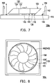
- FIG. 7 is a schematic cross-sectional diagram of a fan assembly according to another embodiment of the disclosure.
- FIG. 8 is a top schematic diagram of the fan assembly of FIG. 7 .
- the fan assembly 100c further includes a light-collecting component 170.
- the light-collecting component 170 is, for example, a convex lens or any component that may collect light.
- the light-collecting component 170 is disposed on the blade bottom surface 126 of at least one blade 124 and extends towards the direction of the base 110.
- the light-collecting component 170 is disposed on an end of the blade bottom surface 126 (in FIG. 7 ) away from the central part 121. A portion of the light emitted by the light-emitting unit 130 is adapted for being focused on the inclined inner surface 142 by the light-collecting component 170. Therefore, the user may see the visual effect at a rotating and particularly bright point.
- the light-collecting component 170 may be disposed on a plurality of blades 124, or the light-collecting component 170 may be disposed on each of the blades 124 to obtain different visual effects.
- FIG. 9 is a top schematic diagram of a fan assembly according to another embodiment of the disclosure.
- a light-collecting component 170d is a bar-shaped structure, extending from an end close to the central part 121 to an end away from the central part 121 on the blade 124. Therefore, the user may see the visual effect on a rotating and particularly bright bar-shaped area.
- the light-collecting component 170d may be disposed on a plurality of blades 124, or the light-collecting component 170d may be disposed on each of the blades 124 to obtain different visual effects.
- the light-emitting unit of the fan assembly of the disclosure is located between the base and the central part of the fan, and the lighting effect component is disposed on the base and surrounds the light-emitting unit.
- the projection of the lighting effect component onto the base is greater than the projection of the fan onto the base, and the height of the lighting effect component protruding from the base is less than the distance between the blade top surface and the base.
- the light emitted by the light-emitting unit may be emitted to the inclined inner surface of the lighting effect component, and may be reflected by the inclined inner surface to be directed towards the direction away from the base.
- the low-height lighting effect component is less likely to damage the wind flow of the fan; therefore, a good heat-dissipation effect may still be maintained.
Landscapes
- Engineering & Computer Science (AREA)
- General Engineering & Computer Science (AREA)
- Mechanical Engineering (AREA)
- Structures Of Non-Positive Displacement Pumps (AREA)
Abstract
Description
- The disclosure relates to a fan assembly, and in particular to a fan assembly with special visual effects.
- As users have an increasing demand for visual effects, a goal of current research concerning a fan assembly on a motherboard is, in addition to providing heat-dissipation effects, providing users with special visual effects on the premise of taking into account heat-dissipation performance.
- The disclosure provides a fan assembly that takes into account heat-dissipation performance and provides special visual effects.
- A fan assembly of the disclosure includes a base, a fan, a light-emitting unit, and a lighting effect component. The fan is rotatably disposed above the base, and includes a central part and multiple blades extending outwards from the central part, and each of these blades has a blade top surface away from the base. The light-emitting unit is disposed on the base and located between the base and the central part of the fan. The lighting effect component is disposed on the base and surrounds the light-emitting unit; a projection of the lighting effect component onto the base is greater than a projection of the fan onto the base; a height of the lighting effect component protruding from the base is less than a distance between the blade top surface and the base; the lighting effect component includes an inclined inner surface; and light emitted by the light-emitting unit is adapted for emitting to the inclined inner surface and being reflected towards a direction away from the base.
- In an embodiment of the disclosure, each of the above-mentioned blades includes a blade bottom surface opposite to the blade top surface, and the height of the lighting effect component protruding from the base is less than or equal to a distance between the blade bottom surface and the base.
- In an embodiment of the disclosure, the above-mentioned fan assembly further includes a fan guard which is disposed on the base and surrounds the fan and the lighting effect component. A height of the fan guard protruding from the base is greater than or equal to the distance between the blade top surface and the base.
- In an embodiment of the disclosure, the above-mentioned fan assembly further includes an arc reflector which is disposed on a central part bottom surface of the central part of the fan and rotates as the fan rotates. The arc reflector includes an opening, and a portion of the light emitted by the light-emitting unit is adapted for being reflected by the arc reflector and passing through the opening to be incident on the inclined inner surface.
- In an embodiment of the disclosure, the above-mentioned fan assembly further includes a light-collecting component; each of these blades includes a blade bottom surface opposite to the blade top surface; the light-collecting component is disposed on the blade bottom surface of one of the blades and extends towards the direction of the base; and a portion of the light emitted by the light-emitting unit is adapted for being focused on the inclined inner surface by the light-collecting component.
- In an embodiment of the disclosure, the above-mentioned light-collecting component is disposed on an end of the blade bottom surface away from the central part.
- In an embodiment of the disclosure, the above-mentioned light-collecting component is a bar-shaped structure extending from an end close to the central part to an end away from the central part of the blade bottom surface.
- In an embodiment of the disclosure, an inclination angle of the above-mentioned inclined inner surface is between 30 degrees and 60 degrees.
- In an embodiment of the disclosure, the above-mentioned light-emitting unit includes a red light-emitting diode, a green light-emitting diode, and a blue light-emitting diode.
- In an embodiment of the disclosure, the above-mentioned lighting effect component is in a closed annular shape.
- Based on the above, the light-emitting unit of the fan assembly of the disclosure is located between the base and the central part of the fan, and the lighting effect component is disposed on the base and surrounds the light-emitting unit. The projection of the lighting effect component onto the base is greater than the projection of the fan onto the base, and the height of the lighting effect component protruding from the base is less than the distance between the blade top surface and the base. The light emitted by the light-emitting unit is emitted to the inclined inner surface of the lighting effect component, and is reflected by the inclined inner surface to be directed towards the direction away from the base. With the above design, users see the visual effect generated by the light being reflected by the lighting effect component from the front side of the fan assembly. In addition, since the height of the lighting effect component protruding from the base is less than the distance between the blade top surface and the base, the low-height lighting effect component is less likely to damage the wind flow of the fan; therefore, a good heat-dissipation effect is still maintained.
-
-
FIG. 1 is a schematic cross-sectional diagram of a fan assembly according to an embodiment of the disclosure. -
FIG. 2 is a top schematic diagram of the fan assembly ofFIG. 1 . -
FIG. 3 is a schematic diagram of a light-emitting unit of the fan assembly ofFIG. 1 . -
FIG. 4 is a schematic cross-sectional diagram of a fan assembly according to another embodiment of the disclosure. -
FIG. 5 is a schematic cross-sectional diagram of a fan assembly according to another embodiment of the disclosure. -
FIG. 6 is a schematic diagram of light of a light-emitting unit of the fan assembly ofFIG. 5 being reflected by an arc reflector. -
FIG. 7 is a schematic cross-sectional diagram of a fan assembly according to another embodiment of the disclosure. -
FIG. 8 is a top schematic diagram of the fan assembly ofFIG. 7 . -
FIG. 9 is a top schematic diagram of a fan assembly according to another embodiment of the disclosure. -
FIG. 1 is a schematic cross-sectional diagram of a fan assembly according to an embodiment of the disclosure.FIG. 2 is a top schematic diagram of the fan assembly ofFIG. 1 . Referring toFIGS. 1 and 2 , in this embodiment, afan assembly 100 is, for example, disposed on a display card (not shown), but a heat source applied by thefan assembly 100 is not limited thereto. Thefan assembly 100 includes abase 110, afan 120, a light-emitting unit 130, and alighting effect component 140. - The
fan 120 is rotatably disposed above thebase 110. Thefan 120 includes acentral part 121 andmultiple blades 124 extending outwards from thecentral part 121. The light-emitting unit 130 is disposed on thebase 110 and between thebase 110 and thecentral part 121 of thefan 120. - The
lighting effect component 140 is disposed on thebase 110 and surrounds the light-emitting unit 130. As shown inFIG. 2 , in this embodiment, the projection of thelighting effect component 140 onto thebase 110 is greater than the projection of thefan 120 onto thebase 110. Therefore, thelighting effect component 140 is not blocked by thefan 120, and the user may see thelighting effect component 140 from the front side (for example, looking down from the top ofFIG. 1 ) of thefan assembly 100. - In this embodiment, the
lighting effect component 140 includes an inclinedinner surface 142 that is inclined towards the light-emittingunit 130. An inclination angle θ of the inclinedinner surface 142 is between 30 degrees and 60 degrees, for example, 45 degrees, but the inclination angle θ of the inclinedinner surface 142 is not limited thereto. In addition, in this embodiment, thelighting effect component 140 is in a closed annular shape, but in other embodiments, thelighting effect component 140 may be in a non-closed annular shape. - In this embodiment, the light-emitting
unit 130 may, for example, emit light radially, and the light emitted by the light-emittingunit 130 is adapted for emitting to the inclinedinner surface 142 of thelighting effect component 140 and being reflected towards a direction away from thebase 110. Therefore, the user may see the visual effect generated by the light being reflected by thelighting effect component 140 from the front side of thefan assembly 100. - It should be noted that, as shown in
FIG. 1 , theblades 124 have a bladetop surface 125 away from thebase 110 and ablade bottom surface 126 opposite to theblade top surface 125. A height H1 of thelighting effect component 140 protruding from thebase 110 is less than a distance D1 between theblade top surface 125 and thebase 110. In this embodiment, the height H1 of thelighting effect component 140 protruding from thebase 110 is less than or equal to a distance D2 between theblade bottom surface 126 and thebase 110. Since the design of a low-heightlighting effect component 140 is less likely to damage the wind flow of thefan 120, thefan assembly 100 may maintain a good heat-dissipation effect. - In addition, the
fan assembly 100 may optionally include afan guard 150. As shown inFIG. 1 , thefan guard 150 is disposed on thebase 110 and surrounds thefan 120 and thelighting effect component 140. A height H2 of thefan guard 150 protruding from thebase 110 is greater than or equal to the distance D1 between theblade top surface 125 and thebase 110, so thefan guard 150 may be used to protect thefan 120 by reducing the probability of foreign objects directly contacting thefan 120. In addition, thefan guard 150 may also be used to prevent the user's hand from directly contacting therotating blades 124. -
FIG. 3 is a schematic diagram of a light-emitting unit of the fan assembly ofFIG. 1 . Referring toFIG. 3 , in this embodiment, the light-emittingunit 130 includes a redlight emitting diode 132, a greenlight emitting diode 134, and a bluelight emitting diode 136. Of course, in other embodiments, the light-emittingunit 130 may only have a monochromatic light emitting diode, and the type of the light-emittingunit 130 is not limited thereto. - The light-emitting
unit 130 may be controlled by a controller (not shown) to generate different light-emitting effects. Specifically, a manufacturer may use a tachometer pin (TACHO Pin, not shown) of thefan 120 to measure the waveform of the rotation speed of thefan 120 according to the desired lighting effect, and write relevant information into the controller. The controller may control the switches of the redlight emitting diode 132, the greenlight emitting diode 134, and the bluelight emitting diode 136 in the light-emittingunit 130 according to the rotation speed to obtain different lighting effects. Alternatively, all the colors that the light-emittingunit 130 may emit may be displayed on thelighting effect component 140. - Therefore, the user may see different colors on the
lighting effect component 140 or see effects such as marquee, gradient color, breathing light effect, flashing light effect, etc. Due to the principle of persistence of vision, these lighting effects may appear in human eyes at the same time or sequentially. -
FIG. 4 is a schematic cross-sectional diagram of a fan assembly according to another embodiment of the disclosure. Referring toFIG. 4 , the main difference between a fan assembly 100a ofFIG. 4 and thefan assembly 100 ofFIG. 1 is as follows. In this embodiment, a height H3 of thelighting effect component 140 protruding from thebase 110 is greater than the distance D2 between the bladebottom surface 126 and thebase 110, and is less than the distance D1 between the bladetop surface 125 and thebase 110. Since the height H3 of thelighting effect component 140 is still low, thelighting effect component 140 is less likely to affect the airflow of thefan 120. In addition, since the height of thelighting effect component 140 ofFIG. 4 is relatively large, thelighting effect component 140 ofFIG. 4 may have a larger inclinedinner surface 142, and may provide a more significant visual effect. -
FIG. 5 is a schematic cross-sectional diagram of a fan assembly according to another embodiment of the disclosure.FIG. 6 is a schematic diagram of light of a light-emitting unit of the fan assembly ofFIG. 5 being reflected by an arc reflector. Referring toFIGS. 5 and 6 , the main difference between afan assembly 100b inFIG. 5 and thefan assembly 100 inFIG. 1 is as follows. In this embodiment, thefan assembly 100b further includes anarc reflector 160, which is disposed on a centralpart bottom surface 122 of thecentral part 121 of thefan 120 and rotates as thefan 120 rotates. - As shown in
FIG. 6 , in this embodiment, thearc reflector 160, for example, surrounds 180 degrees of the light-emittingunit 130. But in other embodiments, thearc reflector 160 may surround an angle between 60 degrees and 240 degrees of light-emittingunit 130, and the angle of the light-emittingunit 130 being surrounded by thearc reflector 160 is not limited thereto. - The
arc reflector 160 includes anopening 162, and a portion of the light emitted by the light-emittingunit 130 moves away from the direction of thearc reflector 160 and is directly directed towards the inclinedinner surface 142 of thelighting effect component 140 inFIG. 5 . A portion of the light emitted by the light-emittingunit 130 is adapted for being reflected by thearc reflector 160 and passing through theopening 162 ofFIG. 6 to be incident on the inclinedinner surface 142 of thelighting effect component 140. - In other words, the light emitted by the light-emitting
unit 130 may be concentrated on a portion of the inclinedinner surface 142 of thelighting effect component 140, so that said portion of the inclinedinner surface 142 is particularly bright. In addition, since thearc reflector 160 rotates as thefan 120 rotates, based on the persistence of vision method, the entire inclinedinner surface 142 of thelighting effect component 140 uniformly emits brighter light. Of course, when thefan 120 rotates at a low speed, since the persistence of vision is not obvious, the light may be reflected by therotating arc reflector 160 to different portions on the inclinedinner surface 142 of thelighting effect component 140, so that a dynamic light effect may be presented. -
FIG. 7 is a schematic cross-sectional diagram of a fan assembly according to another embodiment of the disclosure.FIG. 8 is a top schematic diagram of the fan assembly ofFIG. 7 . Referring toFIGS. 7 and 8 , the main difference between afan assembly 100c inFIG. 7 and thefan assembly 100 inFIG. 1 is as follows. In this embodiment, thefan assembly 100c further includes a light-collectingcomponent 170. The light-collectingcomponent 170 is, for example, a convex lens or any component that may collect light. The light-collectingcomponent 170 is disposed on the bladebottom surface 126 of at least oneblade 124 and extends towards the direction of thebase 110. - The light-collecting
component 170 is disposed on an end of the blade bottom surface 126 (inFIG. 7 ) away from thecentral part 121. A portion of the light emitted by the light-emittingunit 130 is adapted for being focused on the inclinedinner surface 142 by the light-collectingcomponent 170. Therefore, the user may see the visual effect at a rotating and particularly bright point. In other embodiments, the light-collectingcomponent 170 may be disposed on a plurality ofblades 124, or the light-collectingcomponent 170 may be disposed on each of theblades 124 to obtain different visual effects. -
FIG. 9 is a top schematic diagram of a fan assembly according to another embodiment of the disclosure. Referring toFIG. 9 , the main difference between afan assembly 100d inFIG. 9 and thefan assembly 100c inFIG. 8 is as follows. In this embodiment, a light-collectingcomponent 170d is a bar-shaped structure, extending from an end close to thecentral part 121 to an end away from thecentral part 121 on theblade 124. Therefore, the user may see the visual effect on a rotating and particularly bright bar-shaped area. Similarly, in other embodiments, the light-collectingcomponent 170d may be disposed on a plurality ofblades 124, or the light-collectingcomponent 170d may be disposed on each of theblades 124 to obtain different visual effects. - In summary, the light-emitting unit of the fan assembly of the disclosure is located between the base and the central part of the fan, and the lighting effect component is disposed on the base and surrounds the light-emitting unit. The projection of the lighting effect component onto the base is greater than the projection of the fan onto the base, and the height of the lighting effect component protruding from the base is less than the distance between the blade top surface and the base. The light emitted by the light-emitting unit may be emitted to the inclined inner surface of the lighting effect component, and may be reflected by the inclined inner surface to be directed towards the direction away from the base. With the above design, users may see the visual effect generated by the light being reflected by the lighting effect component from the front side of the fan assembly. In addition, since the height of the lighting effect component protruding from the base is less than the distance between the blade top surface and the base, the low-height lighting effect component is less likely to damage the wind flow of the fan; therefore, a good heat-dissipation effect may still be maintained.
Claims (10)
- A fan assembly (100, 100a, 100b, 100c, 100d), comprising:a base (110);a fan (120), rotatably disposed above the base (110), comprising a central part (121) and a plurality of blades (124) extending outwards from the central part (121), wherein each of the blades (124) has a blade top surface (125) away from the base (110);a light-emitting unit (130), disposed on the base (110), located between the base (110) and the central part (121) of the fan (120); anda lighting effect component (140), disposed on the base (110), surrounding the light-emitting unit (130), wherein a projection of the lighting effect component (140) onto the base (110) is greater than a projection of the fan (120) onto the base (110), a height (HI, H3) of the lighting effect component (140) protruding from the base (110) is less than a distance (D1) between the blade top surface (125) and the base (110), the lighting effect component (140) comprises an inclined inner surface (142), and light emitted by the light-emitting unit (130) is adapted for emitting to the inclined inner surface (142) and being reflected towards a direction away from the base (110).
- The fan assembly (100, 100a, 100b, 100c, 100d) according to claim 1, wherein each of the blades (124) comprises a blade bottom surface (126) opposite to the blade top surface (125), and the height (HI, H3) of the lighting effect component (140) protruding from the base (110) is less than or equal to a distance (D2) between the blade bottom surface (126) and the base (110).
- The fan assembly (100, 100a, 100b, 100c, 100d) according to claim 1, further comprising:
a fan guard (150), disposed on the base (110), surrounding the fan (120) and the lighting effect component (140), wherein a height (H2) of the fan guard (150) protruding from the base (110) is greater than or equal to the distance (D1) between the blade top surface (125) and the base (110). - The fan assembly (100, 100a, 100b, 100c, 100d) according to claim 1, further comprising:
an arc reflector (160), disposed on a central part bottom surface (122) of the central part (121) of the fan (120), rotating as the fan (120) rotates, wherein the arc reflector (160) comprises an opening (162), and a portion of the light emitted by the light-emitting unit (130) is adapted for being reflected by the arc reflector (160) and passing through the opening (162) to be incident on the inclined inner surface (142). - The fan assembly (100, 100a, 100b, 100c, 100d) according to claim 1, further comprising:
a light-collecting component (170, 170d), wherein each of the blades (124) comprises a blade bottom surface (126) opposite to the blade top surface (125), the light-collecting component (170, 170d) is disposed on the blade bottom surface (126) of one of the blades (124) and extends towards the direction of the base (110), and a portion of the light emitted by the light-emitting unit (130) is adapted for being focused on the inclined inner surface (142) by the light-collecting component (170, 170d). - The fan assembly (100, 100a, 100b, 100c, 100d) according to claim 5, wherein the light-collecting component (170, 170d) is disposed on an end of the blade bottom surface (126) away from the central part (121).
- The fan assembly (100, 100a, 100b, 100c, 100d) according to claim 5, wherein the light-collecting component (170, 170d) is a bar-shaped structure extending from an end close to the central part (121) to an end away from the central part (121) of the blade bottom surface (126).
- The fan assembly (100, 100a, 100b, 100c, 100d) according to claim 1, wherein an inclination angle (θ) of the inclined inner surface (142) is between 30 degrees and 60 degrees.
- The fan assembly (100, 100a, 100b, 100c, 100d) according to claim 1, wherein the light-emitting unit (130) comprises a red light-emitting diode (132), a green light-emitting diode (134), and a blue light-emitting diode (136).
- The fan assembly (100, 100a, 100b, 100c, 100d) according to claim 1, wherein the lighting effect component (140) is in a closed annular shape.
Applications Claiming Priority (1)
| Application Number | Priority Date | Filing Date | Title |
|---|---|---|---|
| TW109144366A TWI750955B (en) | 2020-12-16 | 2020-12-16 | Fan assembly |
Publications (2)
| Publication Number | Publication Date |
|---|---|
| EP4015834A1 true EP4015834A1 (en) | 2022-06-22 |
| EP4015834B1 EP4015834B1 (en) | 2023-11-22 |
Family
ID=78829335
Family Applications (1)
| Application Number | Title | Priority Date | Filing Date |
|---|---|---|---|
| EP21213603.0A Active EP4015834B1 (en) | 2020-12-16 | 2021-12-10 | Fan assembly |
Country Status (3)
| Country | Link |
|---|---|
| US (1) | US11773860B2 (en) |
| EP (1) | EP4015834B1 (en) |
| TW (1) | TWI750955B (en) |
Citations (4)
| Publication number | Priority date | Publication date | Assignee | Title |
|---|---|---|---|---|
| US6790003B1 (en) * | 2003-06-09 | 2004-09-14 | Act-Rx Technology Corporation | Cooling fan with flashing light effect |
| CN207795629U (en) * | 2018-01-02 | 2018-08-31 | 政久兴业股份有限公司 | Cooling fan with luminous effect |
| US20190063740A1 (en) * | 2017-08-25 | 2019-02-28 | Giga-Byte Technology Co., Ltd. | Light Emitting Fan Device with a Hybrid of Light-Reflective and Light-Guiding Mechanisms |
| EP3613989A1 (en) * | 2018-08-22 | 2020-02-26 | Sunonwealth Electric Machine Industry Co., Ltd. | Fan |
Family Cites Families (6)
| Publication number | Priority date | Publication date | Assignee | Title |
|---|---|---|---|---|
| KR100985123B1 (en) * | 2008-11-12 | 2010-10-05 | (주)선영에스티 | Axial Fan Fan with Photocatalytic Function |
| TWM500287U (en) * | 2014-10-15 | 2015-05-01 | Giga Byte Tech Co Ltd | A fan assembly |
| CN206368833U (en) * | 2016-12-06 | 2017-08-01 | 东莞市育恒电子塑胶有限公司 | A reflective light cooling fan |
| US10101020B2 (en) * | 2017-02-15 | 2018-10-16 | Silverstone Technology Co., Ltd. | Uniformly luminous fan shield structure and fan having the same |
| CN207795630U (en) * | 2018-01-02 | 2018-08-31 | 政久兴业股份有限公司 | Heat radiation fan with luminous effect |
| US10082286B1 (en) * | 2018-01-24 | 2018-09-25 | Dynaeon Industrial Co., Ltd. | Cooling fan with light-emitting effect |
-
2020
- 2020-12-16 TW TW109144366A patent/TWI750955B/en active
-
2021
- 2021-12-10 EP EP21213603.0A patent/EP4015834B1/en active Active
- 2021-12-10 US US17/547,226 patent/US11773860B2/en active Active
Patent Citations (4)
| Publication number | Priority date | Publication date | Assignee | Title |
|---|---|---|---|---|
| US6790003B1 (en) * | 2003-06-09 | 2004-09-14 | Act-Rx Technology Corporation | Cooling fan with flashing light effect |
| US20190063740A1 (en) * | 2017-08-25 | 2019-02-28 | Giga-Byte Technology Co., Ltd. | Light Emitting Fan Device with a Hybrid of Light-Reflective and Light-Guiding Mechanisms |
| CN207795629U (en) * | 2018-01-02 | 2018-08-31 | 政久兴业股份有限公司 | Cooling fan with luminous effect |
| EP3613989A1 (en) * | 2018-08-22 | 2020-02-26 | Sunonwealth Electric Machine Industry Co., Ltd. | Fan |
Also Published As
| Publication number | Publication date |
|---|---|
| TW202225564A (en) | 2022-07-01 |
| US11773860B2 (en) | 2023-10-03 |
| EP4015834B1 (en) | 2023-11-22 |
| US20220186923A1 (en) | 2022-06-16 |
| TWI750955B (en) | 2021-12-21 |
Similar Documents
| Publication | Publication Date | Title |
|---|---|---|
| TWI699707B (en) | Method for controlling structured light projector, depth camera and electronic device | |
| US4667274A (en) | Self-illumination patch assembly | |
| TWI439222B (en) | Fan module | |
| US4217625A (en) | Lighted instrument dial face display | |
| CN106199947A (en) | Color wheel and projection device | |
| WO2009062043A1 (en) | An apparatus configured to provide functional and aesthetic lighting from a fan | |
| CN103133411A (en) | Fan module | |
| TWI681128B (en) | fan | |
| US11435073B2 (en) | Combined lamp and bladeless fan | |
| US11428383B1 (en) | Light projector | |
| EP4015834B1 (en) | Fan assembly | |
| CN102369389A (en) | Lighting device having a plurality of light sources and a reflection arrangement and reflector unit | |
| EP3173689A1 (en) | Electronic luminary device with simulated flame | |
| CN103133371B (en) | Fan module | |
| US9791126B2 (en) | Spherical lighting device | |
| TWI491805B (en) | Heat-dissipating device | |
| CN114635864B (en) | Fan assembly | |
| TWI729967B (en) | Light emitting fan assembly | |
| CN114688053B (en) | Luminous fan assembly | |
| US11815251B1 (en) | Smart lighting device equipped with user interface capable of gesture recognition | |
| CN207004882U (en) | A cooling side light-emitting fan of a computer mainframe | |
| CN203395639U (en) | Headlamp having rotary positioning function | |
| CN213629950U (en) | Luminous ball | |
| TWI674362B (en) | Glare cooling fan and its light guide fan wheel | |
| CN109058935B (en) | Light source device and light source system |
Legal Events
| Date | Code | Title | Description |
|---|---|---|---|
| PUAI | Public reference made under article 153(3) epc to a published international application that has entered the european phase |
Free format text: ORIGINAL CODE: 0009012 |
|
| STAA | Information on the status of an ep patent application or granted ep patent |
Free format text: STATUS: THE APPLICATION HAS BEEN PUBLISHED |
|
| AK | Designated contracting states |
Kind code of ref document: A1 Designated state(s): AL AT BE BG CH CY CZ DE DK EE ES FI FR GB GR HR HU IE IS IT LI LT LU LV MC MK MT NL NO PL PT RO RS SE SI SK SM TR |
|
| STAA | Information on the status of an ep patent application or granted ep patent |
Free format text: STATUS: REQUEST FOR EXAMINATION WAS MADE |
|
| 17P | Request for examination filed |
Effective date: 20221019 |
|
| RBV | Designated contracting states (corrected) |
Designated state(s): AL AT BE BG CH CY CZ DE DK EE ES FI FR GB GR HR HU IE IS IT LI LT LU LV MC MK MT NL NO PL PT RO RS SE SI SK SM TR |
|
| GRAP | Despatch of communication of intention to grant a patent |
Free format text: ORIGINAL CODE: EPIDOSNIGR1 |
|
| STAA | Information on the status of an ep patent application or granted ep patent |
Free format text: STATUS: GRANT OF PATENT IS INTENDED |
|
| RIC1 | Information provided on ipc code assigned before grant |
Ipc: F21V 33/00 20060101ALI20230622BHEP Ipc: F04D 29/38 20060101ALI20230622BHEP Ipc: F04D 29/00 20060101AFI20230622BHEP |
|
| INTG | Intention to grant announced |
Effective date: 20230711 |
|
| GRAS | Grant fee paid |
Free format text: ORIGINAL CODE: EPIDOSNIGR3 |
|
| GRAA | (expected) grant |
Free format text: ORIGINAL CODE: 0009210 |
|
| STAA | Information on the status of an ep patent application or granted ep patent |
Free format text: STATUS: THE PATENT HAS BEEN GRANTED |
|
| P01 | Opt-out of the competence of the unified patent court (upc) registered |
Effective date: 20230919 |
|
| AK | Designated contracting states |
Kind code of ref document: B1 Designated state(s): AL AT BE BG CH CY CZ DE DK EE ES FI FR GB GR HR HU IE IS IT LI LT LU LV MC MK MT NL NO PL PT RO RS SE SI SK SM TR |
|
| REG | Reference to a national code |
Ref country code: GB Ref legal event code: FG4D |
|
| REG | Reference to a national code |
Ref country code: CH Ref legal event code: EP Ref country code: DE Ref legal event code: R096 Ref document number: 602021007040 Country of ref document: DE |
|
| REG | Reference to a national code |
Ref country code: IE Ref legal event code: FG4D |
|
| REG | Reference to a national code |
Ref country code: LT Ref legal event code: MG9D |
|
| REG | Reference to a national code |
Ref country code: NL Ref legal event code: MP Effective date: 20231122 |
|
| PG25 | Lapsed in a contracting state [announced via postgrant information from national office to epo] |
Ref country code: GR Free format text: LAPSE BECAUSE OF FAILURE TO SUBMIT A TRANSLATION OF THE DESCRIPTION OR TO PAY THE FEE WITHIN THE PRESCRIBED TIME-LIMIT Effective date: 20240223 |
|
| PG25 | Lapsed in a contracting state [announced via postgrant information from national office to epo] |
Ref country code: IS Free format text: LAPSE BECAUSE OF FAILURE TO SUBMIT A TRANSLATION OF THE DESCRIPTION OR TO PAY THE FEE WITHIN THE PRESCRIBED TIME-LIMIT Effective date: 20240322 |
|
| PG25 | Lapsed in a contracting state [announced via postgrant information from national office to epo] |
Ref country code: LT Free format text: LAPSE BECAUSE OF FAILURE TO SUBMIT A TRANSLATION OF THE DESCRIPTION OR TO PAY THE FEE WITHIN THE PRESCRIBED TIME-LIMIT Effective date: 20231122 |
|
| REG | Reference to a national code |
Ref country code: AT Ref legal event code: MK05 Ref document number: 1634085 Country of ref document: AT Kind code of ref document: T Effective date: 20231122 |
|
| PG25 | Lapsed in a contracting state [announced via postgrant information from national office to epo] |
Ref country code: NL Free format text: LAPSE BECAUSE OF FAILURE TO SUBMIT A TRANSLATION OF THE DESCRIPTION OR TO PAY THE FEE WITHIN THE PRESCRIBED TIME-LIMIT Effective date: 20231122 |
|
| PG25 | Lapsed in a contracting state [announced via postgrant information from national office to epo] |
Ref country code: AT Free format text: LAPSE BECAUSE OF FAILURE TO SUBMIT A TRANSLATION OF THE DESCRIPTION OR TO PAY THE FEE WITHIN THE PRESCRIBED TIME-LIMIT Effective date: 20231122 |
|
| PG25 | Lapsed in a contracting state [announced via postgrant information from national office to epo] |
Ref country code: ES Free format text: LAPSE BECAUSE OF FAILURE TO SUBMIT A TRANSLATION OF THE DESCRIPTION OR TO PAY THE FEE WITHIN THE PRESCRIBED TIME-LIMIT Effective date: 20231122 |
|
| PG25 | Lapsed in a contracting state [announced via postgrant information from national office to epo] |
Ref country code: NL Free format text: LAPSE BECAUSE OF FAILURE TO SUBMIT A TRANSLATION OF THE DESCRIPTION OR TO PAY THE FEE WITHIN THE PRESCRIBED TIME-LIMIT Effective date: 20231122 Ref country code: LT Free format text: LAPSE BECAUSE OF FAILURE TO SUBMIT A TRANSLATION OF THE DESCRIPTION OR TO PAY THE FEE WITHIN THE PRESCRIBED TIME-LIMIT Effective date: 20231122 Ref country code: IS Free format text: LAPSE BECAUSE OF FAILURE TO SUBMIT A TRANSLATION OF THE DESCRIPTION OR TO PAY THE FEE WITHIN THE PRESCRIBED TIME-LIMIT Effective date: 20240322 Ref country code: GR Free format text: LAPSE BECAUSE OF FAILURE TO SUBMIT A TRANSLATION OF THE DESCRIPTION OR TO PAY THE FEE WITHIN THE PRESCRIBED TIME-LIMIT Effective date: 20240223 Ref country code: ES Free format text: LAPSE BECAUSE OF FAILURE TO SUBMIT A TRANSLATION OF THE DESCRIPTION OR TO PAY THE FEE WITHIN THE PRESCRIBED TIME-LIMIT Effective date: 20231122 Ref country code: BG Free format text: LAPSE BECAUSE OF FAILURE TO SUBMIT A TRANSLATION OF THE DESCRIPTION OR TO PAY THE FEE WITHIN THE PRESCRIBED TIME-LIMIT Effective date: 20240222 Ref country code: AT Free format text: LAPSE BECAUSE OF FAILURE TO SUBMIT A TRANSLATION OF THE DESCRIPTION OR TO PAY THE FEE WITHIN THE PRESCRIBED TIME-LIMIT Effective date: 20231122 Ref country code: PT Free format text: LAPSE BECAUSE OF FAILURE TO SUBMIT A TRANSLATION OF THE DESCRIPTION OR TO PAY THE FEE WITHIN THE PRESCRIBED TIME-LIMIT Effective date: 20240322 |
|
| PG25 | Lapsed in a contracting state [announced via postgrant information from national office to epo] |
Ref country code: SE Free format text: LAPSE BECAUSE OF FAILURE TO SUBMIT A TRANSLATION OF THE DESCRIPTION OR TO PAY THE FEE WITHIN THE PRESCRIBED TIME-LIMIT Effective date: 20231122 Ref country code: RS Free format text: LAPSE BECAUSE OF FAILURE TO SUBMIT A TRANSLATION OF THE DESCRIPTION OR TO PAY THE FEE WITHIN THE PRESCRIBED TIME-LIMIT Effective date: 20231122 Ref country code: PL Free format text: LAPSE BECAUSE OF FAILURE TO SUBMIT A TRANSLATION OF THE DESCRIPTION OR TO PAY THE FEE WITHIN THE PRESCRIBED TIME-LIMIT Effective date: 20231122 Ref country code: NO Free format text: LAPSE BECAUSE OF FAILURE TO SUBMIT A TRANSLATION OF THE DESCRIPTION OR TO PAY THE FEE WITHIN THE PRESCRIBED TIME-LIMIT Effective date: 20240222 Ref country code: LV Free format text: LAPSE BECAUSE OF FAILURE TO SUBMIT A TRANSLATION OF THE DESCRIPTION OR TO PAY THE FEE WITHIN THE PRESCRIBED TIME-LIMIT Effective date: 20231122 Ref country code: HR Free format text: LAPSE BECAUSE OF FAILURE TO SUBMIT A TRANSLATION OF THE DESCRIPTION OR TO PAY THE FEE WITHIN THE PRESCRIBED TIME-LIMIT Effective date: 20231122 |
|
| PG25 | Lapsed in a contracting state [announced via postgrant information from national office to epo] |
Ref country code: DK Free format text: LAPSE BECAUSE OF FAILURE TO SUBMIT A TRANSLATION OF THE DESCRIPTION OR TO PAY THE FEE WITHIN THE PRESCRIBED TIME-LIMIT Effective date: 20231122 |
|
| PG25 | Lapsed in a contracting state [announced via postgrant information from national office to epo] |
Ref country code: CZ Free format text: LAPSE BECAUSE OF FAILURE TO SUBMIT A TRANSLATION OF THE DESCRIPTION OR TO PAY THE FEE WITHIN THE PRESCRIBED TIME-LIMIT Effective date: 20231122 |
|
| PG25 | Lapsed in a contracting state [announced via postgrant information from national office to epo] |
Ref country code: SK Free format text: LAPSE BECAUSE OF FAILURE TO SUBMIT A TRANSLATION OF THE DESCRIPTION OR TO PAY THE FEE WITHIN THE PRESCRIBED TIME-LIMIT Effective date: 20231122 |
|
| PG25 | Lapsed in a contracting state [announced via postgrant information from national office to epo] |
Ref country code: SM Free format text: LAPSE BECAUSE OF FAILURE TO SUBMIT A TRANSLATION OF THE DESCRIPTION OR TO PAY THE FEE WITHIN THE PRESCRIBED TIME-LIMIT Effective date: 20231122 Ref country code: SK Free format text: LAPSE BECAUSE OF FAILURE TO SUBMIT A TRANSLATION OF THE DESCRIPTION OR TO PAY THE FEE WITHIN THE PRESCRIBED TIME-LIMIT Effective date: 20231122 Ref country code: RO Free format text: LAPSE BECAUSE OF FAILURE TO SUBMIT A TRANSLATION OF THE DESCRIPTION OR TO PAY THE FEE WITHIN THE PRESCRIBED TIME-LIMIT Effective date: 20231122 Ref country code: IT Free format text: LAPSE BECAUSE OF FAILURE TO SUBMIT A TRANSLATION OF THE DESCRIPTION OR TO PAY THE FEE WITHIN THE PRESCRIBED TIME-LIMIT Effective date: 20231122 Ref country code: EE Free format text: LAPSE BECAUSE OF FAILURE TO SUBMIT A TRANSLATION OF THE DESCRIPTION OR TO PAY THE FEE WITHIN THE PRESCRIBED TIME-LIMIT Effective date: 20231122 Ref country code: DK Free format text: LAPSE BECAUSE OF FAILURE TO SUBMIT A TRANSLATION OF THE DESCRIPTION OR TO PAY THE FEE WITHIN THE PRESCRIBED TIME-LIMIT Effective date: 20231122 Ref country code: CZ Free format text: LAPSE BECAUSE OF FAILURE TO SUBMIT A TRANSLATION OF THE DESCRIPTION OR TO PAY THE FEE WITHIN THE PRESCRIBED TIME-LIMIT Effective date: 20231122 |
|
| PG25 | Lapsed in a contracting state [announced via postgrant information from national office to epo] |
Ref country code: LU Free format text: LAPSE BECAUSE OF NON-PAYMENT OF DUE FEES Effective date: 20231210 |
|
| REG | Reference to a national code |
Ref country code: DE Ref legal event code: R097 Ref document number: 602021007040 Country of ref document: DE |
|
| PG25 | Lapsed in a contracting state [announced via postgrant information from national office to epo] |
Ref country code: MC Free format text: LAPSE BECAUSE OF FAILURE TO SUBMIT A TRANSLATION OF THE DESCRIPTION OR TO PAY THE FEE WITHIN THE PRESCRIBED TIME-LIMIT Effective date: 20231122 |
|
| REG | Reference to a national code |
Ref country code: BE Ref legal event code: MM Effective date: 20231231 |
|
| PG25 | Lapsed in a contracting state [announced via postgrant information from national office to epo] |
Ref country code: MC Free format text: LAPSE BECAUSE OF FAILURE TO SUBMIT A TRANSLATION OF THE DESCRIPTION OR TO PAY THE FEE WITHIN THE PRESCRIBED TIME-LIMIT Effective date: 20231122 Ref country code: LU Free format text: LAPSE BECAUSE OF NON-PAYMENT OF DUE FEES Effective date: 20231210 |
|
| PLBE | No opposition filed within time limit |
Free format text: ORIGINAL CODE: 0009261 |
|
| STAA | Information on the status of an ep patent application or granted ep patent |
Free format text: STATUS: NO OPPOSITION FILED WITHIN TIME LIMIT |
|
| REG | Reference to a national code |
Ref country code: IE Ref legal event code: MM4A |
|
| PG25 | Lapsed in a contracting state [announced via postgrant information from national office to epo] |
Ref country code: IE Free format text: LAPSE BECAUSE OF NON-PAYMENT OF DUE FEES Effective date: 20231210 |
|
| PG25 | Lapsed in a contracting state [announced via postgrant information from national office to epo] |
Ref country code: BE Free format text: LAPSE BECAUSE OF NON-PAYMENT OF DUE FEES Effective date: 20231231 |
|
| PG25 | Lapsed in a contracting state [announced via postgrant information from national office to epo] |
Ref country code: SI Free format text: LAPSE BECAUSE OF FAILURE TO SUBMIT A TRANSLATION OF THE DESCRIPTION OR TO PAY THE FEE WITHIN THE PRESCRIBED TIME-LIMIT Effective date: 20231122 |
|
| 26N | No opposition filed |
Effective date: 20240823 |
|
| PG25 | Lapsed in a contracting state [announced via postgrant information from national office to epo] |
Ref country code: SI Free format text: LAPSE BECAUSE OF FAILURE TO SUBMIT A TRANSLATION OF THE DESCRIPTION OR TO PAY THE FEE WITHIN THE PRESCRIBED TIME-LIMIT Effective date: 20231122 Ref country code: IE Free format text: LAPSE BECAUSE OF NON-PAYMENT OF DUE FEES Effective date: 20231210 Ref country code: BE Free format text: LAPSE BECAUSE OF NON-PAYMENT OF DUE FEES Effective date: 20231231 |
|
| PG25 | Lapsed in a contracting state [announced via postgrant information from national office to epo] |
Ref country code: FI Free format text: LAPSE BECAUSE OF FAILURE TO SUBMIT A TRANSLATION OF THE DESCRIPTION OR TO PAY THE FEE WITHIN THE PRESCRIBED TIME-LIMIT Effective date: 20231122 |
|
| PG25 | Lapsed in a contracting state [announced via postgrant information from national office to epo] |
Ref country code: CY Free format text: LAPSE BECAUSE OF FAILURE TO SUBMIT A TRANSLATION OF THE DESCRIPTION OR TO PAY THE FEE WITHIN THE PRESCRIBED TIME-LIMIT; INVALID AB INITIO Effective date: 20211210 |
|
| REG | Reference to a national code |
Ref country code: CH Ref legal event code: PL |
|
| PGFP | Annual fee paid to national office [announced via postgrant information from national office to epo] |
Ref country code: FR Payment date: 20250930 Year of fee payment: 5 |
|
| PG25 | Lapsed in a contracting state [announced via postgrant information from national office to epo] |
Ref country code: CH Free format text: LAPSE BECAUSE OF NON-PAYMENT OF DUE FEES Effective date: 20241231 |
|
| PG25 | Lapsed in a contracting state [announced via postgrant information from national office to epo] |
Ref country code: TR Free format text: LAPSE BECAUSE OF FAILURE TO SUBMIT A TRANSLATION OF THE DESCRIPTION OR TO PAY THE FEE WITHIN THE PRESCRIBED TIME-LIMIT Effective date: 20231122 |
|
| PGFP | Annual fee paid to national office [announced via postgrant information from national office to epo] |
Ref country code: DE Payment date: 20250930 Year of fee payment: 5 |
|
| PGFP | Annual fee paid to national office [announced via postgrant information from national office to epo] |
Ref country code: GB Payment date: 20251001 Year of fee payment: 5 |
|
| PG25 | Lapsed in a contracting state [announced via postgrant information from national office to epo] |
Ref country code: HU Free format text: LAPSE BECAUSE OF FAILURE TO SUBMIT A TRANSLATION OF THE DESCRIPTION OR TO PAY THE FEE WITHIN THE PRESCRIBED TIME-LIMIT; INVALID AB INITIO Effective date: 20211210 |