EP3173689A1 - Electronic luminary device with simulated flame - Google Patents
Electronic luminary device with simulated flame Download PDFInfo
- Publication number
- EP3173689A1 EP3173689A1 EP16205327.6A EP16205327A EP3173689A1 EP 3173689 A1 EP3173689 A1 EP 3173689A1 EP 16205327 A EP16205327 A EP 16205327A EP 3173689 A1 EP3173689 A1 EP 3173689A1
- Authority
- EP
- European Patent Office
- Prior art keywords
- light
- projection screen
- source
- sources
- circuitry
- Prior art date
- Legal status (The legal status is an assumption and is not a legal conclusion. Google has not performed a legal analysis and makes no representation as to the accuracy of the status listed.)
- Withdrawn
Links
Images


Classifications
-
- F—MECHANICAL ENGINEERING; LIGHTING; HEATING; WEAPONS; BLASTING
- F21—LIGHTING
- F21S—NON-PORTABLE LIGHTING DEVICES; SYSTEMS THEREOF; VEHICLE LIGHTING DEVICES SPECIALLY ADAPTED FOR VEHICLE EXTERIORS
- F21S10/00—Lighting devices or systems producing a varying lighting effect
- F21S10/04—Lighting devices or systems producing a varying lighting effect simulating flames
- F21S10/043—Lighting devices or systems producing a varying lighting effect simulating flames by selectively switching fixed light sources
-
- F—MECHANICAL ENGINEERING; LIGHTING; HEATING; WEAPONS; BLASTING
- F21—LIGHTING
- F21S—NON-PORTABLE LIGHTING DEVICES; SYSTEMS THEREOF; VEHICLE LIGHTING DEVICES SPECIALLY ADAPTED FOR VEHICLE EXTERIORS
- F21S6/00—Lighting devices intended to be free-standing
- F21S6/001—Lighting devices intended to be free-standing being candle-shaped
-
- F—MECHANICAL ENGINEERING; LIGHTING; HEATING; WEAPONS; BLASTING
- F21—LIGHTING
- F21V—FUNCTIONAL FEATURES OR DETAILS OF LIGHTING DEVICES OR SYSTEMS THEREOF; STRUCTURAL COMBINATIONS OF LIGHTING DEVICES WITH OTHER ARTICLES, NOT OTHERWISE PROVIDED FOR
- F21V5/00—Refractors for light sources
- F21V5/04—Refractors for light sources of lens shape
-
- F—MECHANICAL ENGINEERING; LIGHTING; HEATING; WEAPONS; BLASTING
- F21—LIGHTING
- F21V—FUNCTIONAL FEATURES OR DETAILS OF LIGHTING DEVICES OR SYSTEMS THEREOF; STRUCTURAL COMBINATIONS OF LIGHTING DEVICES WITH OTHER ARTICLES, NOT OTHERWISE PROVIDED FOR
- F21V7/00—Reflectors for light sources
- F21V7/0008—Reflectors for light sources providing for indirect lighting
-
- F—MECHANICAL ENGINEERING; LIGHTING; HEATING; WEAPONS; BLASTING
- F21—LIGHTING
- F21W—INDEXING SCHEME ASSOCIATED WITH SUBCLASSES F21K, F21L, F21S and F21V, RELATING TO USES OR APPLICATIONS OF LIGHTING DEVICES OR SYSTEMS
- F21W2121/00—Use or application of lighting devices or systems for decorative purposes, not provided for in codes F21W2102/00 – F21W2107/00
- F21W2121/002—Candle holders for birthday or anniversary cakes
-
- F—MECHANICAL ENGINEERING; LIGHTING; HEATING; WEAPONS; BLASTING
- F21—LIGHTING
- F21Y—INDEXING SCHEME ASSOCIATED WITH SUBCLASSES F21K, F21L, F21S and F21V, RELATING TO THE FORM OR THE KIND OF THE LIGHT SOURCES OR OF THE COLOUR OF THE LIGHT EMITTED
- F21Y2115/00—Light-generating elements of semiconductor light sources
- F21Y2115/10—Light-emitting diodes [LED]
Definitions
- Flameless candles may provide an illusion of a real (flamed) candle, but without the risk of fire damage.
- a real candle flame moves in physical space.
- Moving parts may be undesirable for various reasons. For example, moving parts may tend to become damaged, such as during shipping, by mishandling, or by unintentional events.
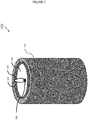
- FIGS. 1-3B illustrate an electronic candle 100, according to techniques of the present application.
- the electronic candle 100 may include a side wall 102 having an upper region and a lower region.
- a base 150 (see FIG. 2 ) may be engaged with the lower region of the side wall 102.
- An upper surface 106 may extend from the upper region of the sidewall 102 to form an upper recess 104.
- the upper recess 104 may have a variety of different shapes.
- the upper recess 104 may be shaped like a bowl or a portion of a bowl.
- the upper region of the side wall 102 may have a varying height around the top perimeter of the electronic candle 100.
- the upper recess 104 may have a rounded or flat bottom surface.
- the upper recess 104 may have a smooth or textured bottom surface.
- the upper recess 104 may have a cylindrical shape.
- the projection screen 110 may extend upwardly from the riser 140.
- the projection screen 110 may be rigidly affixed to the riser 140 at or near the top of the riser 140.
- the projection screen 110 may be integral with the riser 140.
- the projection screen 110 may be a separate portion rigidly attached to the riser 140 (for example, glued or attached at more than one place).
- By rigidly affixing the projection screen 110 with the riser 140 it may be possible to fix the position of the projection screen 110 with respect to the upper surface 106.
- the projection screen 110 may be affixed to the upper surface 106 or to the sidewall 102 instead of the riser 140.
- the surface of the projection screen 110 may be flat, concave, or convex.
- the surface of the projection screen 110 may be various combinations of flat, concave, and/or convex.
- the projection screen 110 may have a two-dimensional or three-dimensional appearance.
- the projection screen 110 may have a flame shape. Such a shape may be static, in that it does not change.
- the projection screen 110 may have one or more projection surfaces.
- the projection screen 110 may have two projection surfaces - front and back.
- the projection screen 110 may have additional projection surfaces.
- the projection screen 110 may have three or more surfaces, each receiving light from one or more sources of light.
- the projection screen 110 may have surfaces that wrap around to form a shape with substantial depth.
- the projection screen 110 may have a three-dimensional shape resembling an actual candle flame. In such an example, sources of light may be located around the projection screen 110 and may project onto the projection screen 110.
- each source of light 120, 130 may project light (either completely or partially) through the aperture 108 in the upper surface 106 and onto the projection screen 110.
- the light emitted from each source of light 120, 130 may radiate according to a beam width.
- the beam widths for the light emitted from the sources of light 120, 130 may be between 30-35 degrees.
- the beam axis for the light emitted from each of the sources of light may intersect with the primary plane of the projection screen 110. Such an intersection may have an angle between 20-40 degrees.
- the sources of light 120, 130 may project light onto the same side or different sides of the projection screen 110.
- the source of light 120 may project light onto the front side of the projection screen 110, while the source of light 130 may project light onto the back side of the projection screen 110. If the projection screen 110 is translucent, light projected onto one side may penetrate to the other side.
Abstract
Description
- Generally, this application relates to techniques for constructing flameless candles. Specifically, this application discloses techniques for simulating a candle flame.
- Flameless candles may provide an illusion of a real (flamed) candle, but without the risk of fire damage. A real candle flame moves in physical space. In order to simulate such movement, some have used an element that also moves in physical space. Moving parts, however, may be undesirable for various reasons. For example, moving parts may tend to become damaged, such as during shipping, by mishandling, or by unintentional events.
- Furthermore, flameless candles with moving parts may require additional components or systems to cause the moving parts to move. Such components or systems may include fans or magnetic systems. These components or systems may add cost to a flameless candle device
- According to techniques of the application, a device may include a side wall, a base, and an upper surface. The side wall may have an upper region and a lower region. The base may be engaged with the lower region of the side wall. The upper surface may extend from the upper region of the side wall to form an upper recess.
- The device may include a projection screen extending upwardly through an aperture in the upper surface. The position of the projection screen may be fixed with respect to the position of the upper surface. The projection screen may be flat or may have a concavity or convexity. The projection screen may have a general two-dimensional or three-dimensional appearance. The projection screen may be shaped like a flame. The projection may have a primary plane. The projection screen may be translucent. The projection screen may be formed from a material such as plastic, glass, or metal.
- A first source of light may be positioned below the upper surface and may to project light through the aperture onto the projection screen. A second source of light may be positioned below the upper surface and may to project light through the aperture onto the projection screen. The positions of the first source of light and the second source of light may also be fixed with respect to the position of the projection screen.
- The light from the first and second sources of light may be projected onto the front side of the projection screen or onto the front and back side of the projection screen. Light projected onto one side of the projection screen may penetrate through to the other side of the projection screen. Each of the sources of light may emit light with a beam axis and a beam width. One or more of the beam axes may intersect with the primary plane of the projection screen at an angle between 20° to 40°. One or more of the beam widths may be between 30° to 35°.
- The sources of light may be positioned to project light onto different areas of the projection screen. These areas may be distinct or may overlap.
- Circuitry may electrically connect to the first source of light and the second source of light. The circuitry may independently control intensities of the light projected by the first source of light and the second source of light.
-
-
FIG. 1 illustrates an electronic candle, according to techniques of the present application. -
FIG. 2 illustrates a portion of an electronic candle, according to techniques of the present application. -
FIGS. 3A and3B illustrate a projection screen and light sources, according to techniques of the present application. - The foregoing summary, as well as the following detailed description of certain techniques of the present application, will be better understood when read in conjunction with the appended drawings. For the purposes of illustration, certain techniques are shown in the drawings. It should be understood, however, that the claims are not limited to the arrangements and instrumentality shown in the attached drawings. Furthermore, the appearance shown in the drawings is one of many ornamental appearances that can be employed to achieve the stated functions of the system.
-
FIGS. 1-3B illustrate anelectronic candle 100, according to techniques of the present application. As shown inFIG. 1 , theelectronic candle 100 may include aside wall 102 having an upper region and a lower region. A base 150 (seeFIG. 2 ) may be engaged with the lower region of theside wall 102. Anupper surface 106 may extend from the upper region of thesidewall 102 to form anupper recess 104. Theupper recess 104 may have a variety of different shapes. Theupper recess 104 may be shaped like a bowl or a portion of a bowl. For example, the upper region of theside wall 102 may have a varying height around the top perimeter of theelectronic candle 100. Theupper recess 104 may have a rounded or flat bottom surface. Theupper recess 104 may have a smooth or textured bottom surface. Theupper recess 104 may have a cylindrical shape. - A
projection screen 110 may extend upwardly through anaperture 108 in theupper surface 106. The position of theprojection screen 110 may be fixed with respect to theupper surface 106. Of course, an undue amount of force could cause theprojection screen 110 to deflect or otherwise change position with respect to theupper surface 106. However, an anticipated movement of the electronic candle 100 (for example, picking up or putting down the candle, rotating the candle, or turning the candle upside down) may not influence the position of the projection screen with respect to theupper surface 106. - As shown in
FIG. 2 , theelectronic candle 100 may include abase 150. Thebase 150 may accommodate batteries in abattery compartment 160. Thebase 150 may also accommodatecircuitry 170. Thebattery compartment 160 andcircuitry 170 need not be located in or around thebase 150, and could be located at other areas of theelectronic candle 100. For example, thecircuitry 170 may be embedded in one or more of the sources oflight circuitry 170 and sources oflight battery compartment 160. - A
riser 140 may extend upwardly from the base. Sources oflight riser 140. The sources oflight - The
projection screen 110 may extend upwardly from theriser 140. Theprojection screen 110 may be rigidly affixed to theriser 140 at or near the top of theriser 140. For example, theprojection screen 110 may be integral with theriser 140. Theprojection screen 110 may be a separate portion rigidly attached to the riser 140 (for example, glued or attached at more than one place). By rigidly affixing theprojection screen 110 with theriser 140, it may be possible to fix the position of theprojection screen 110 with respect to theupper surface 106. There may be other ways to fix the positions of theprojection screen 110 and theupper surface 106. For example, theprojection screen 110 may be affixed to theupper surface 106 or to thesidewall 102 instead of theriser 140. - The
projection screen 110 may be rigid. Theprojection screen 110 may be formed from one or more materials, such as glass, plastic, metal, or foil. Such material(s) may be at least partially reflective. Theprojection screen 110 may be opaque, semi-opaque, clear, frosted, or translucent. Theprojection screen 110 may have a mesh or other textured surface. Theprojection screen 110 may facilitate display of holographic images. - The surface of the
projection screen 110 may be flat, concave, or convex. The surface of theprojection screen 110 may be various combinations of flat, concave, and/or convex. Theprojection screen 110 may have a two-dimensional or three-dimensional appearance. Theprojection screen 110 may have a flame shape. Such a shape may be static, in that it does not change. Theprojection screen 110 may have one or more projection surfaces. For example, theprojection screen 110 may have two projection surfaces - front and back. Theprojection screen 110 may have additional projection surfaces. For example, theprojection screen 110 may have three or more surfaces, each receiving light from one or more sources of light. Theprojection screen 110 may have surfaces that wrap around to form a shape with substantial depth. For example, theprojection screen 110 may have a three-dimensional shape resembling an actual candle flame. In such an example, sources of light may be located around theprojection screen 110 and may project onto theprojection screen 110. - The
projection screen 110 may be of uniform color or may have different colors. For example, theprojection screen 110 may be painted or patterned to show a simulated wick. In order to provide an illusion of a real candle flame, theprojection screen 110 may have darker colors near an area where a wick would be expected. Theprojection screen 110 may have different colors (for example, blue, white, orange, or yellow) to simulate different flame temperatures and intensities as a viewer may expect in a real candle flame. The colors may be chosen in combination with light colors emitted from the sources oflight - The sources of
light circuitry 170 through one ormore conductors 130. Thecircuitry 170 may include a processor and one or more computer-readable storage devices that store software instructions for execution by the processor. Thecircuitry 170 may independently control one or more different aspects of the light projected by the sources oflight circuitry 170 may be capable of separately controlling the intensity or color for each source oflight - The
circuitry 170 may illuminate each source oflight circuitry 170, which may, in turn, adjust the intensity levels in sequences according to the light sensor output signal (for example, boost the intensities under higher light). As another example, an output signal from a sound sensor (not shown) could be received by thecircuitry 170, which may, in turn, adjust the intensity levels in sequences according to the sound sensor output signal (for example, adjust the frequency of the intensity changes in response to the character of received sound). - As illustrated in
FIG. 3A , theprojection screen 110 extends upwardly through theaperture 108 in theupper surface 106. While not shown in this example, the position of theprojection screen 110 is fixed with respect to theupper surface 106. The sources oflight upper surface 106. They may be positioned and configured in such a manner to project light through theaperture 108 and onto theprojection screen 110. The positions of the sources oflight projection screen 110. - The
projection screen 110 may have a primary plane. Such a plane may be substantially vertical and may generally face the direction of emitted light from the sources oflight projection screen 110 is not entirely flat, it should be understood that theprojection screen 110 still may have a primary plane. - Referring to
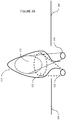
FIG. 3B , each source oflight aperture 108 in theupper surface 106 and onto theprojection screen 110. The light emitted from each source oflight light projection screen 110. Such an intersection may have an angle between 20-40 degrees. The sources oflight projection screen 110. For example, the source of light 120 may project light onto the front side of theprojection screen 110, while the source of light 130 may project light onto the back side of theprojection screen 110. If theprojection screen 110 is translucent, light projected onto one side may penetrate to the other side. - The source of light 120 may project light onto an
area 122 on theprojection screen 110. The source of light 130 may project light onto anarea 132 on theprojection screen 110. Theareas areas 122 may have different or similar shapes. The shapes may be influenced by the beam width of projected light, angle of incidence of the beam axis with the primary plane of theprojection screen 110, the distance of a source oflight projection screen 110, the contour of the light-receiving surface of theprojection screen 110, or by other factors. For example, it may be possible to provide lenses, apertures, or the like to form a beam of light having a particular shape. Such shape(s) may influence the shape of area(s) 122, 132. - At least some of the light emitted from the sources of
light projection screen 110 and towards a viewer's eye. For example, the light may be reflected directly off of theprojection screen 110 and to the viewer's eye without passing through any intervening materials. - As discussed above, the intensities or colors of each of the sources of
light circuitry 170. Through such independent control, it may be possible to simulate a candle flame. For example, it may be possible to simulate the physical movement and varying intensity profiles of a candle flame without employing moving parts. - More than two sources of light may be used. For example, three sources of light may be projected onto one side of the
projection screen 110. Each of these sources of light may be independently controlled, such as by the techniques discussed above. As another example, four sources of light may be used. Two of the sources may project light onto one side of theprojection screen 110 and the other two sources may project light onto another side of theprojection screen 110. - It will be understood by those skilled in the art that various changes may be made and equivalents may be substituted without departing from the scope of the novel techniques disclosed in this application. In addition, many modifications may be made to adapt a particular situation or material to the teachings of the novel techniques without departing from its scope. For example, while an electronic candle has been primarily disclosed, similar techniques could be applied to other luminary devices, such as wall sconces, lanterns, paper candles, or tiki torches. Therefore, it is intended that the novel techniques not be limited to the particular techniques disclosed, but that they will include all techniques falling within the scope of the appended claims.
Claims (8)
- A device for simulating a flame, comprising:a side wall including an upper region and a lower region;an upper surface extending from the upper region of the side wall toward a central axis of the device, wherein an upper recess is formed at least in part by the upper surface;a projection screen arranged to extend upwardly from an aperture in the upper surface;a first source of light located below the upper surface and configured to project a first beam of light through the aperture onto the projection screen;a first lens configured to alter the first beam of light; andcircuitry configured to control an intensity of the first source of light.
- The device of claim 1, further comprising:a second source of light located below the upper surface and configured to project a second beam of light through the aperture onto the projection screen;a second lens configured to alter the second beam of light; andwherein the circuitry is further configured to independently control the intensity of the first beam of light and the intensity of the second beam of light.
- The device of claim 2, wherein the first source of light is positioned to project light onto a front side of the projection screen thereby defining a first area, the second source of light is positioned to project light through the aperture onto the front side of the projection screen thereby defining a second area, wherein the second area is overlapping but different than the first area.
- The device of claim 1, wherein the projection screen comprises a flame-shape.
- The device of claim 1, wherein the projection screen is offset from a central axis of the aperture through the upper surface.
- The device of claim 1, wherein the projection screen is rigid.
- The device of claim 1, wherein the upper recess is formed at least in part by the upper surface and a portion of the side wall.
- The device of claim 1, wherein the projection screen does not move with respect to the upper surface.
Applications Claiming Priority (2)
| Application Number | Priority Date | Filing Date | Title |
|---|---|---|---|
| US201261607942P | 2012-03-07 | 2012-03-07 | |
| EP12870606.6A EP2823229B8 (en) | 2012-03-07 | 2012-10-23 | Electronic luminary device with simulated flame |
Related Parent Applications (2)
| Application Number | Title | Priority Date | Filing Date |
|---|---|---|---|
| EP12870606.6A Division-Into EP2823229B8 (en) | 2012-03-07 | 2012-10-23 | Electronic luminary device with simulated flame |
| EP12870606.6A Division EP2823229B8 (en) | 2012-03-07 | 2012-10-23 | Electronic luminary device with simulated flame |
Publications (1)
| Publication Number | Publication Date |
|---|---|
| EP3173689A1 true EP3173689A1 (en) | 2017-05-31 |
Family
ID=49117173
Family Applications (2)
| Application Number | Title | Priority Date | Filing Date |
|---|---|---|---|
| EP12870606.6A Active EP2823229B8 (en) | 2012-03-07 | 2012-10-23 | Electronic luminary device with simulated flame |
| EP16205327.6A Withdrawn EP3173689A1 (en) | 2012-03-07 | 2012-10-23 | Electronic luminary device with simulated flame |
Family Applications Before (1)
| Application Number | Title | Priority Date | Filing Date |
|---|---|---|---|
| EP12870606.6A Active EP2823229B8 (en) | 2012-03-07 | 2012-10-23 | Electronic luminary device with simulated flame |
Country Status (11)
| Country | Link |
|---|---|
| EP (2) | EP2823229B8 (en) |
| CN (2) | CN104272027B (en) |
| AU (2) | AU2012372764B2 (en) |
| BR (1) | BR112014022213A2 (en) |
| CA (1) | CA2866846C (en) |
| DK (1) | DK2823229T3 (en) |
| ES (1) | ES2617513T3 (en) |
| HK (1) | HK1205785A1 (en) |
| MX (1) | MX339650B (en) |
| PT (1) | PT2823229T (en) |
| WO (1) | WO2013133867A1 (en) |
Families Citing this family (6)
| Publication number | Priority date | Publication date | Assignee | Title |
|---|---|---|---|---|
| US20160161071A1 (en) * | 2014-12-03 | 2016-06-09 | Winvic Sales Inc. | Solar-Powered Flameless Candle |
| CN106500041A (en) * | 2015-09-06 | 2017-03-15 | 天津市祥泰带钢有限公司 | A kind of electronic intelligence candlestick |
| CN107883332A (en) * | 2017-09-22 | 2018-04-06 | 南通亚泰蜡业工艺品有限公司 | A kind of Simulated electrical candle |
| CN107883331A (en) * | 2017-09-22 | 2018-04-06 | 南通亚泰蜡业工艺品有限公司 | A kind of Simulated electrical candle |
| CN107726238A (en) | 2017-09-22 | 2018-02-23 | 南通亚泰蜡业工艺品有限公司 | A kind of Simulated electrical candle |
| WO2020155030A1 (en) * | 2019-01-31 | 2020-08-06 | 深圳市柔宇科技有限公司 | Display method and electronic torch |
Citations (5)
| Publication number | Priority date | Publication date | Assignee | Title |
|---|---|---|---|---|
| US20010033488A1 (en) * | 2000-02-14 | 2001-10-25 | Alex Chliwnyj | Electronic flame |
| US20080112154A1 (en) * | 2006-11-10 | 2008-05-15 | Disney Enterprises, Inc. | Standalone flame simulator |
| CN101865413A (en) * | 2010-06-28 | 2010-10-20 | 李晓锋 | Electronic luminescent device for simulating true fire and method for simulating true fire by same |
| EP2290290A1 (en) * | 2009-08-24 | 2011-03-02 | Truma Gerätetechnik GmbH & Co. KG | Device for optical simulation of a chimney fire |
| US20110127914A1 (en) * | 2008-09-30 | 2011-06-02 | Disney Enterprises, Inc. | Kinetic flame device |
Family Cites Families (11)
| Publication number | Priority date | Publication date | Assignee | Title |
|---|---|---|---|---|
| SE504864C2 (en) * | 1995-02-15 | 1997-05-20 | Rolf Berg | Battery light and lamp unit for imitation of candles |
| US5924784A (en) * | 1995-08-21 | 1999-07-20 | Chliwnyj; Alex | Microprocessor based simulated electronic flame |
| US6616308B2 (en) * | 2001-08-14 | 2003-09-09 | Jenesis International, Inc. | Imitation candle |
| CN2747446Y (en) * | 2004-09-29 | 2005-12-21 | 厦门星星工艺品有限公司 | Electronic candle |
| US20060146544A1 (en) * | 2005-01-05 | 2006-07-06 | Leung Moses K | LED candle |
| CN2775459Y (en) * | 2005-04-07 | 2006-04-26 | 李普 | Electronic artificial candle |
| US20070242259A1 (en) * | 2006-03-30 | 2007-10-18 | Kazuiku Kawakami | Three-dimensional pseudo-image presenting apparatus, method therefor and three-dimensional pseudo-image presenting system |
| US20080129226A1 (en) * | 2006-12-05 | 2008-06-05 | Innovative Instruments, Inc. | Simulated Open Flame Illumination |
| TWM311848U (en) * | 2006-12-21 | 2007-05-11 | Guo-Lung Lin | Electric candle of dual-light sources |
| US20100254155A1 (en) * | 2009-04-07 | 2010-10-07 | Rensselaer Polytechnic Institute | Simulated Candle and Method For Simulating a Candle |
| US20110279034A1 (en) * | 2010-04-14 | 2011-11-17 | Scott Lucas | Light fixture with flameless candle |
-
2012
- 2012-10-23 WO PCT/US2012/061435 patent/WO2013133867A1/en active Application Filing
- 2012-10-23 AU AU2012372764A patent/AU2012372764B2/en not_active Ceased
- 2012-10-23 CN CN201280073029.1A patent/CN104272027B/en active Active
- 2012-10-23 EP EP12870606.6A patent/EP2823229B8/en active Active
- 2012-10-23 MX MX2014010748A patent/MX339650B/en active IP Right Grant
- 2012-10-23 DK DK12870606.6T patent/DK2823229T3/en active
- 2012-10-23 BR BR112014022213A patent/BR112014022213A2/en not_active IP Right Cessation
- 2012-10-23 PT PT128706066T patent/PT2823229T/en unknown
- 2012-10-23 CA CA2866846A patent/CA2866846C/en active Active
- 2012-10-23 EP EP16205327.6A patent/EP3173689A1/en not_active Withdrawn
- 2012-10-23 CN CN201610642664.7A patent/CN106247201A/en active Pending
- 2012-10-23 ES ES12870606.6T patent/ES2617513T3/en active Active
-
2015
- 2015-07-03 HK HK15106332.7A patent/HK1205785A1/en not_active IP Right Cessation
-
2016
- 2016-08-16 AU AU2016216562A patent/AU2016216562A1/en not_active Abandoned
Patent Citations (5)
| Publication number | Priority date | Publication date | Assignee | Title |
|---|---|---|---|---|
| US20010033488A1 (en) * | 2000-02-14 | 2001-10-25 | Alex Chliwnyj | Electronic flame |
| US20080112154A1 (en) * | 2006-11-10 | 2008-05-15 | Disney Enterprises, Inc. | Standalone flame simulator |
| US20110127914A1 (en) * | 2008-09-30 | 2011-06-02 | Disney Enterprises, Inc. | Kinetic flame device |
| EP2290290A1 (en) * | 2009-08-24 | 2011-03-02 | Truma Gerätetechnik GmbH & Co. KG | Device for optical simulation of a chimney fire |
| CN101865413A (en) * | 2010-06-28 | 2010-10-20 | 李晓锋 | Electronic luminescent device for simulating true fire and method for simulating true fire by same |
Also Published As
| Publication number | Publication date |
|---|---|
| AU2012372764A1 (en) | 2014-09-25 |
| EP2823229B8 (en) | 2017-05-24 |
| CA2866846A1 (en) | 2013-09-12 |
| AU2012372764B2 (en) | 2016-05-19 |
| EP2823229B1 (en) | 2016-12-21 |
| WO2013133867A1 (en) | 2013-09-12 |
| CN106247201A (en) | 2016-12-21 |
| MX339650B (en) | 2016-06-02 |
| MX2014010748A (en) | 2015-03-20 |
| BR112014022213A2 (en) | 2019-09-24 |
| CA2866846C (en) | 2015-11-17 |
| ES2617513T3 (en) | 2017-06-19 |
| PT2823229T (en) | 2017-03-17 |
| CN104272027B (en) | 2016-08-24 |
| EP2823229A4 (en) | 2015-10-14 |
| HK1205785A1 (en) | 2015-12-24 |
| EP2823229A1 (en) | 2015-01-14 |
| DK2823229T3 (en) | 2017-03-06 |
| CN104272027A (en) | 2015-01-07 |
| AU2016216562A1 (en) | 2016-09-01 |
Similar Documents
| Publication | Publication Date | Title |
|---|---|---|
| US10024507B2 (en) | Electronic luminary device with simulated flame | |
| AU2016216562A1 (en) | Electronic luminary device with simulated flame | |
| US10125946B2 (en) | Luminaire and a method for providing task lighting and decorative lighting | |
| CA3011418C (en) | Artificial candle with flame simulator | |
| US10197235B2 (en) | Multiple light source artificial moving flame | |
| US10948145B2 (en) | Artificial candle with flame simulator | |
| CN107013826A (en) | Orientable lens for LED matrix | |
| US9915408B2 (en) | LED lighting fixture | |
| CN105042507A (en) | Light emitting device, surface light source device and display apparatus | |
| US9791126B2 (en) | Spherical lighting device | |
| CN103511935A (en) | Lighting device | |
| TWI670448B (en) | Light source module | |
| US10100990B1 (en) | Artificial LED candle | |
| CN205261367U (en) | Lighting device | |
| EP3102871B1 (en) | Electric lighting devices | |
| US20160091724A1 (en) | Stereoscopic kaleidoscope and projecting device | |
| TWM488261U (en) | Kaleidoscopic magic mirror device | |
| JP2014203686A (en) | Led lighting device | |
| JP2019076369A (en) | Light-emitting device for game machine | |
| JP2016007780A (en) | Decorative luminaire | |
| JP2017152301A (en) | Projector |
Legal Events
| Date | Code | Title | Description |
|---|---|---|---|
| PUAI | Public reference made under article 153(3) epc to a published international application that has entered the european phase |
Free format text: ORIGINAL CODE: 0009012 |
|
| AC | Divisional application: reference to earlier application |
Ref document number: 2823229 Country of ref document: EP Kind code of ref document: P |
|
| AK | Designated contracting states |
Kind code of ref document: A1 Designated state(s): AL AT BE BG CH CY CZ DE DK EE ES FI FR GB GR HR HU IE IS IT LI LT LU LV MC MK MT NL NO PL PT RO RS SE SI SK SM TR |
|
| 17P | Request for examination filed |
Effective date: 20171130 |
|
| RBV | Designated contracting states (corrected) |
Designated state(s): AL AT BE BG CH CY CZ DE DK EE ES FI FR GB GR HR HU IE IS IT LI LT LU LV MC MK MT NL NO PL PT RO RS SE SI SK SM TR |
|
| 17Q | First examination report despatched |
Effective date: 20180130 |
|
| STAA | Information on the status of an ep patent application or granted ep patent |
Free format text: STATUS: THE APPLICATION HAS BEEN WITHDRAWN |
|
| RAP1 | Party data changed (applicant data changed or rights of an application transferred) |
Owner name: STERNO HOME INC. |
|
| 18W | Application withdrawn |
Effective date: 20180308 |