EP4015729A1 - Device for mounting a support structure in a suspended ceiling system and suspended ceiling system - Google Patents
Device for mounting a support structure in a suspended ceiling system and suspended ceiling system Download PDFInfo
- Publication number
- EP4015729A1 EP4015729A1 EP20214208.9A EP20214208A EP4015729A1 EP 4015729 A1 EP4015729 A1 EP 4015729A1 EP 20214208 A EP20214208 A EP 20214208A EP 4015729 A1 EP4015729 A1 EP 4015729A1
- Authority
- EP
- European Patent Office
- Prior art keywords
- section
- support structure
- suspended ceiling
- ceiling system
- profile
- Prior art date
- Legal status (The legal status is an assumption and is not a legal conclusion. Google has not performed a legal analysis and makes no representation as to the accuracy of the status listed.)
- Withdrawn
Links
- 239000002184 metal Substances 0.000 description 11
- 239000000463 material Substances 0.000 description 8
- 238000010521 absorption reaction Methods 0.000 description 2
- 239000011491 glass wool Substances 0.000 description 2
- 238000003780 insertion Methods 0.000 description 2
- 230000037431 insertion Effects 0.000 description 2
- 238000009434 installation Methods 0.000 description 2
- 239000004575 stone Substances 0.000 description 2
- 210000002268 wool Anatomy 0.000 description 2
- 230000004308 accommodation Effects 0.000 description 1
- 230000001419 dependent effect Effects 0.000 description 1
- 229910052602 gypsum Inorganic materials 0.000 description 1
- 239000010440 gypsum Substances 0.000 description 1
- 238000010438 heat treatment Methods 0.000 description 1
- 238000012986 modification Methods 0.000 description 1
- 230000004048 modification Effects 0.000 description 1
- 230000000087 stabilizing effect Effects 0.000 description 1
- 238000009423 ventilation Methods 0.000 description 1
- 239000011800 void material Substances 0.000 description 1
- 239000002023 wood Substances 0.000 description 1
Images


Classifications
-
- E—FIXED CONSTRUCTIONS
- E04—BUILDING
- E04B—GENERAL BUILDING CONSTRUCTIONS; WALLS, e.g. PARTITIONS; ROOFS; FLOORS; CEILINGS; INSULATION OR OTHER PROTECTION OF BUILDINGS
- E04B9/00—Ceilings; Construction of ceilings, e.g. false ceilings; Ceiling construction with regard to insulation
- E04B9/18—Means for suspending the supporting construction
- E04B9/183—Means for suspending the supporting construction having a lower side adapted to be connected to a channel of the supporting construction
-
- E—FIXED CONSTRUCTIONS
- E04—BUILDING
- E04B—GENERAL BUILDING CONSTRUCTIONS; WALLS, e.g. PARTITIONS; ROOFS; FLOORS; CEILINGS; INSULATION OR OTHER PROTECTION OF BUILDINGS
- E04B9/00—Ceilings; Construction of ceilings, e.g. false ceilings; Ceiling construction with regard to insulation
- E04B9/006—Ceilings; Construction of ceilings, e.g. false ceilings; Ceiling construction with regard to insulation with means for hanging lighting fixtures or other appliances to the framework of the ceiling
-
- E—FIXED CONSTRUCTIONS
- E04—BUILDING
- E04B—GENERAL BUILDING CONSTRUCTIONS; WALLS, e.g. PARTITIONS; ROOFS; FLOORS; CEILINGS; INSULATION OR OTHER PROTECTION OF BUILDINGS
- E04B9/00—Ceilings; Construction of ceilings, e.g. false ceilings; Ceiling construction with regard to insulation
- E04B9/06—Ceilings; Construction of ceilings, e.g. false ceilings; Ceiling construction with regard to insulation characterised by constructional features of the supporting construction, e.g. cross section or material of framework members
- E04B9/12—Connections between non-parallel members of the supporting construction
- E04B9/127—Connections between non-parallel members of the supporting construction one member being discontinuous and abutting against the other member
Definitions
- the present invention generally relates to device for mounting a support structure in a suspended ceiling system and a suspended ceiling system.
- a suspended ceiling system in a room or in another accommodation may serve a variety of purposes.
- One purpose of having a suspended ceiling system may be to conceal a structural ceiling.
- Another purpose may be to provide improved sound absorption and/or sound attenuation in and outside of the room.
- Another purpose may be to support various equipment installed in the ceiling of a room.
- such equipment may then be installed through the suspended ceiling leaving only desired parts of the equipment visible from the room.
- the resulting plenum space located between the suspended ceiling and a structural ceiling of the room may further be utilized to accommodate e.g. wiring, piping, as well as devices related to heating, ventilation and air condition.
- a conventional suspended ceiling system normally comprise a grid of profiles supporting ceiling tiles arranged in frames formed by the grid of profiles.
- the tiles are typically adapted for sound absorption.
- the grid of profiles typically includes main runners and often also cross runners.
- the main runners are normally attached to the structural ceiling of a room via hangers.
- the hangers are typically made of bars or wires which are attached to the main ceiling and to the main runners such that the main runners become suspended below the main ceiling.
- the cross runners typically connect perpendicular to the main runners and extend in parallel in order to form frames in which the ceiling tiles typically are arranged.
- Some suspended ceilings have ceiling tiles made of rigid materials, such as wood, gypsum or metal. These materials are generally rigid enough to support equipment installed in the suspended ceiling.
- other suspended ceilings have ceiling tiles made of materials such as stone wool or glass wool not having the same load carrying capacity. When utilizing ceiling tiles of stone wool or glass wool it has proven troublesome to install equipment at the suspended ceiling in question.
- an object of the present invention is to provide an improved device for mounting a support structure in a suspended ceiling system and an improved suspended ceiling system.
- Another object is to provide such a device for mounting a support structure in a suspended ceiling system and a suspended ceiling system which are less time consuming to install.
- Another object is to provide such a device for mounting a support structure in a suspended ceiling system and a suspended ceiling system which ensures a reliable connection of a support structure.
- Another object is to provide such a device for mounting a support structure in a suspended ceiling system and a suspended ceiling system which ensure correct positioning of equipment in relation to the suspended ceiling system, which in turn ensure a correct positioning in relation to a tile element of suspended ceiling system.
- a device for mounting a support structure in a suspended ceiling system having the features defined in claim 1 and a suspended ceiling system according to claim 12 are provided according to the present inventive concept. Preferred variations to the inventive concept will be evident from the dependent claims.
- a device for mounting a support structure in a suspended ceiling system comprising a grid of profiles
- the device comprising: a first section connectable to a profile of the grid of profiles, said profile comprising an upstanding web provided with an upper bulb and a lateral support flange, wherein the first section is configured to be mounted over the upper bulb, a second section configured to extend at an oblique angle relative to a mounting plane of the suspended ceiling system when the first section of the device is connected to the profile of the grid of profiles, the second section being provided with a hole configuration adapted to receive an end portion of the support structure.
- the support structure is typically mounted above the ceiling tiles of the suspended ceiling system in case the suspended ceiling system comprises ceiling tiles.
- the support structure may also be used in a suspended ceiling system void of ceiling tiles, i.e. a suspended ceiling system including a grid of profiles without ceiling tiles.
- the suspended ceiling system comprises a grid of profiles.
- the grid of profiles may include main runners and cross runners.
- the cross runners may extend perpendicular in relation to the main runners.
- the main runners and the cross runners typically extend in a mounting plane of the suspended ceiling system, i.e. in a plane parallel to or defined by the suspended ceiling of the suspended ceiling system.
- the device comprises a first section connectable to a profile of the grid of profiles. More specifically, the first section is configured to be mounted over an upper bulb of said profile.
- the profile comprises an upstanding web provided with an upper bulb and a lateral support flange.
- the profile is generally made of metal or comprises metal. The profile may however be made of or comprise other materials such plastic.
- the upper bulb is typically a portion which is made thicker compared to the upstanding web.
- the upper bulb may be folded from a metal sheet.
- the upstanding web may be formed of a metal sheet.
- the lateral support flange is typically configured to support a ceiling tile. A plurality of lateral support flanges may be provided on the profile.
- a plurality of lateral support flanges may be provided on opposite sides of the profile to support two or more ceiling tiles at different sides of the profile.
- the lateral support flange or flanges may be made of a metal sheet.
- the profile, including the upper bulb, the upstanding web and the lateral support flange may be made of a metal sheet.
- the upper bulb, the upstanding web and the lateral support flange may be integrally formed.
- a second section of the device is configured to extend at an oblique angle relative to a mounting plane of the suspended ceiling system when the first section of the device is connected to the profile of the grid of profiles.
- the oblique angle may be any angle which is not parallel to the mounting plane of the suspended ceiling system.
- the second section is provided with a hole configuration adapted to receive an end portion of the support structure.
- the hole configuration may include a single hole or a plurality of holes.
- the hole configuration may resemble an outer shape of the end portion of the support structure, thereby providing a tight fit to the end portion of the support structure.
- the hole configuration may be tailored to fit the outer shape of the end portion of the support structure.
- the hole configuration may be a simple hole or a complex pattern including a plurality of different cuts and/or shapes.
- the hole configuration may resemble an I, a plurality of I:s, a H, a X, an U, a T, an inverted U, or an inverted T to give a few non-limiting examples.
- hole configuration may be any type of hole or holes.
- wording "hole configuration” includes any number of holes having any shape.
- the device may easily be mounted to the profile in a secure and reliable manner.
- the end portion of the support structure may easily be mounted in a secure and reliable manner to the device, hence the support structure may easily be mounted in a secure and reliable manner.
- the support structure may be used to carry the weight of any entities, such as devices, mounted thereon.
- the support structure may be used to stabilize the grid of profiles.
- the device may further comprise a third section extending in the mounting plane of the suspended ceiling system, wherein the third section adjoins the second section, which is advantageous in that the third section may support the support structure.
- the third section may consequently carry the weight or part of the weight of the support structure and any entities, such as devices, mounted thereon. Hence, an even more reliable connection between the device and the support structure may be achieved.
- the third section may be provided with a guide member for guiding the support structure during reception of the end portion of the support structure by the hole configuration, which is advantageous in that insertion of the end portion of the support structure in the hole configuration may be facilitated.
- the guide member may additionally provide an increased stability and reliability to the connection between the device and the end portion of the support structure.
- the guide member may be configured to restrict movement in transversal directions of the support structure while allowing movement in a longitudinal direction thereof, which is advantageous in that insertion of the end portion of the support structure in the hole configuration may be facilitated while an increased stability and reliability to the connection between the device and the end portion of the support structure may be achieved.
- transversal directions may be any directions transversal to the support structure. Transversal directions consequently include lateral and vertical directions of the support structure, or combined directions including lateral and vertical direction components.
- the first section may be joined to the third section via the second section, which is advantageous in that a simple, yet reliable device may be realized.
- the first section may be joined to the second section via the third section, which is advantageous in that a simple, yet reliable device may be realized.
- the hole configuration may be adapted such that the end portion of the support structure has a height which is smaller than a total height of the support structure.
- the first section may be adapted for snap fit mounting over the bulb, which is advantageous in that a reliable and quick mounting may be achieved. Moreover, the need for any tools during mounting may be significantly reduced or eliminated.
- the hole configuration may be adapted to receive the end portion of the support structure having an inverted T cross sectional shape, which is advantageous in that a commonly used shape of the support structure, providing a rigid support structure, may be used.
- the end portion of the support structure may thus be counteracted from moving in a transversal direction thereof while still being easily insertable in a longitudinal direction thereof.
- the first section and the second section may be integrally formed, which is advantageous in that an easily manufacturable reliable device may be achieved.
- the first section, the second section and the third section may be integrally formed, which is advantageous in that an easily manufacturable reliable device may be achieved.
- a suspended ceiling system comprising: a grid of profiles, comprising a profile having an upstanding web provided with an upper bulb and a lateral support flange, a support structure, a device according to the first aspect, wherein the first section of the device is mounted over the upper bulb of the profile, and wherein the hole configuration of the second section receives an end portion of the support structure.
- the system may further comprise a ceiling tile supported by the grid of profiles, wherein the support structure is arranged above the ceiling tile.
- the support structure may consequently be used to support other entities, such as devices, lights or electric equipment, while being concealed by the ceiling tile when viewed from inside of a room.
- the support structure may be arranged at a distance from the ceiling tile in a vertical direction of the suspended ceiling system, which is advantageous in that the arrangement of the support structure may be adapted to suit other entities, such as devices, lights or electric equipment, of different sizes and heights.
- the support structure may have an inverted T cross sectional shape, which is advantageous in that a rigid support structure may be achieved.
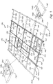
- Fig. 1 is a schematic perspective view conceptually depicting a ceiling system 100.
- the ceiling system 100 comprises a grid of profiles 102.
- the grid of profiles 102 comprises a plurality of profiles 103, some in form of main runners 104a-c extending side by side.
- main runners 104a-c there are three main runners 104a-c illustrated in Fig. 1 .
- two main runners 104d-e are shown in phantom to indicate that the ceiling system 100 may include any number of profiles in form of main runners 104a-e extending side by side.
- the ceiling system 100 may thus be used to form a suspended ceiling of an arbitrary size.
- the grid of profiles 102 further includes profiles 103 in form of cross runners 105.
- the cross runners 105 are optional and may or may not be present in the grid of profiles 102.
- the depicted cross runners 105 are interconnecting the plurality of main runners 104a-e extending side by side, i.e. the cross runners 105 are attached to the respective main runners 104a-e.
- the length of the cross runners 105 is typically about the distance between two adjacent main runners.
- the cross runners may be arranged an oblique angle with respect to the main runners 104a-e. In this case the length of the cross runners 105 are typically adapted so as to interconnect adjacent main runners irrespective of the oblique angle.
- Some cross runners 105 are shown in phantom.
- the depicted ceiling system 100 also includes a plurality of ceiling tiles 120 arranged in the grid of profiles 102. Six ceiling tiles 120 are depicted for reasons of simplicity although any number of ceiling tiles 120 may be used with the ceiling system 100.
- the depicted ceiling system 100 also includes four support structures 106a-c.
- the support structures are mounted to the respective profiles 103 of the grid of profiles 102.
- Support structures 106a are mounted between main runners 104b and 104c in a parallel fashion.
- the support structures 106a carries a device 108 in form of a Wi-Fi repeater.
- the device 108 is mounted between the two support structures 106a.
- the weight of the device 108 is distributed between the two support structures 106a.
- the device 108 and the support structures 106a are visible from a room located underneath the suspended ceiling system 100 since no ceiling tile is present in the location where device 108 and the support structures 106a are located.
- More than two support structures may be used to support a device or similar. In fact, any number of support structures, such as three, five or ten may be used to support a device or similar.
- Support structure 106b is mounted between main runners 104a and 104a and carries a device 110 in form of a lighting device.
- the support structure 106b is not visible from a room located underneath the suspended ceiling system 100 since a ceiling tile 120 is present below the support structure 106b in the location where device 110 and the support structure 106b are located.
- the device 110 is however visible from a room located underneath the suspended ceiling system 100 through an opening in the ceiling tile 120 at hand.
- the device 110 is hence mounted through the ceiling tile 120 at hand.
- Support structure 106c is mounted between two cross runners 105.
- Support structure 106c carries no device or similar but serves the purpose of stabilizing the cross runners 105 and thereby the grid of profiles 102.
- the support structure 106c is not visible from a room located underneath the suspended ceiling system 100 since a ceiling tile 120 is present below the support structure 106c in the location where the support structure 106c is located.
- Each support structure 106a-c is connected to the respective profiles 103 of the grid of profiles 102 by means of a device 200.
- the device 200 is designed for mounting a support structure in a suspended ceiling system 100 and will be described in more detail with reference to Figs. 2a and 2b below.
- the connection of the support structure 106b to the main runner 104b by means of a device 200 is shown as a partial enlarged view in Fig. 1 .
- the connection of the support structure 106c to a cross runner 105 by means of a device 200 is shown as a partial enlarged view in Fig. 1 .
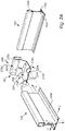
- Fig. 2a and 2b it is conceptually depicted a device 200 for mounting a support structure 106 in a suspended ceiling system 100.
- the suspended ceiling system 100 comprises a grid of profiles 102 including profiles 103.
- a portion of a profile 103 is shown in Figs. 2a and 2b .
- the profile 103 of Figs. 2a and 2b may be a main runner 104a-e or a cross runner 105.
- Figs. 2a and 2b also shows an end portion of a support structure 106.
- the support structure 106 may be any one of the support structures 106a-c of Fig. 1 .
- the depicted profile 103 comprises an upstanding web 103a provided with an upper bulb 103b and a lateral support flange 103c.
- the lateral support flange 103c may carry load and may consequently support the device 200 and/or ceiling tiles 120.
- the device 200 comprises a first section 202.
- the first section 202 is connectable to the profile 103 of the grid of profiles 102.
- the first section 202 is configured to be mounted over the upper bulb 103b of the profile 103.
- the first section 202 is configured to grip around the upper bulb 103b of the profile 103.
- the device 200 comprises a second section 204.
- the second section 204 is configured to extend at an oblique angle relative to a mounting plane of the suspended ceiling system 100 when the first section 202 of the device 200 is connected to the profile 103 of the grid of profiles 102.
- the second section 204 is provided with a hole configuration 206 adapted to receive an end portion of the support structure 106.
- the hole configuration 206 roughly resembles an inverted T.
- the hole configuration 206 is thus adapted to receive the end portion of the depicted support structure 106 which has an inverted T-shape with a flat bottom portion 106d.
- Fig. 2b it is shown how the configuration 206 has received the end portion of the support structure 106.
- the depicted hole configuration 206 is adapted such that the end portion of the support structure 106 has a height h which is smaller than a total height H of the support structure 106.
- the device 200 further comprises a third section 208.
- the first section 202 is joined to the third 208 section via the second section 204.
- the third section 208 extends in the mounting plane of the suspended ceiling system.
- the mounting plane of the suspended ceiling system is typically defined by the grid of profiles 102.
- the mounting plane of the suspended ceiling system may be parallel to a structural ceiling.
- the mounting plane of the suspended ceiling system may not be parallel to a structural ceiling.
- the third section 208 adjoins the second section 204.
- the third section 208 is provided with a guide member 210.
- the depicted guide member 210 is formed of two protrusions 210a, 210b formed on respective sides of the third section 208 and protruding upwards from the same.
- the guide member 210 is provided for guiding the support structure 106 during reception of the end portion of the support structure 106 by the hole configuration 206.
- the respective depicted protrusions 210a, 210b include a respective cut 212a, 212b.
- the cuts 212a, 212b thus forms a path through which the bottom portion 106d of the support structure 106 may be slid into along a longitudinal direction L thereof.
- the cuts 212a, 212b thus guides the support structure 106 into the hole configuration 206 when being received therein.
- the cuts 212a, 212b counteracts that the support structure is lifted and/or twisted, hence making the connection between the device 200 and the support structure more reliable and rigid.
- the guide member 210 is configured to restrict movement in transversal directions T of the support structure 106 while allowing movement in a longitudinal direction L thereof.
- the guide member 210 may be formed of a single protrusion 210a.
- the guide member 210 may be formed of a pin, a screw, a rivet or similar.
- the guide member 210 may or may not be provided with cuts 212a, 212b.
- the first section 202 of the depicted device 200 is adapted for snap fit mounting over the upper bulb 103b of the profile 103.
- the first section 202 is provided with two resilient protrusions 202a, 202b.
- the resilient protrusions 202a, 202b are thus bent back when the first section 202 of the device 200 is pushed over the upper bulb 103b of the profile 103.
- the protrusions springs back below the upper bulb 103b of the profile 103, thus locking the device 200 to the upper bulb 103b of the profile 103.
- the device 200 is counteracted from being lifted once the protrusions 202a, 202b has passed the upper bulb 103b of the profile 103.
- a single protrusion 202a may be used.
- the first section 202 of the depicted device 200 is further provided with a through hole 202d.
- the through hole 202d may be used to secure the device 200 to the upper bulb 103b of the profile 103 by inserting a screw, a rivet or similar through the through hole 202d and into the upper bulb 103b of the profile 103. Such a screw or rivet will thus additionally lock the device 200 to the upper bulb 103b of the profile 103 in a longitudinal direction thereof.
- the first section 202 and the second section 204 of the depicted device 200 are integrally formed.
- the first section 202 and the second section 204 of the depicted device 200 are formed by a metal sheet which is cut and bent to form the device 200.
- the first section 202 and the second section 204 of the device 200 may be formed by any suitable material, such as plastic.
- the first section 202, the second section 204 and the third section 208 of the depicted device 200 are integrally formed.
- the first section 202, the second section 204 and the third section 208 of the depicted device 200 are formed by a metal sheet which is cut and bent to form the device 200.
- the first section 202, the second section 204 and the third section 208 of the device 200 may be formed by any suitable material, such as plastic.
- FIG. 3 it is conceptually depicted a different variant of a device 300 for mounting a support structure 106 in a suspended ceiling system 100.
- the suspended ceiling system 100 comprises a grid of profiles 102 including profiles 103.
- no profile 103 is shown in Fig. 3 , although the device 300 may be mounted correspondingly to the device 200 to a profile 103.
- the device 300 of Fig. 3 may be mounted to a main runner 104a-e or a cross runner 105.
- Fig. 3 also shows an end portion of a differently shaped support structure 320.
- the support structure 320 may correspond to any one of the support structures 106a-c of Fig. 1 .
- the device 300 comprises a first section 302.
- the first section 302 is connectable to the profile 103 of the grid of profiles 102.
- the first section 302 is configured to be mounted over the upper bulb 103b of a profile 103.
- the first section 302 is configured to grip around the upper bulb 103b of a profile 103.
- the device 300 comprises a second section 304.
- the second section 304 is configured to extend at an oblique angle relative to a mounting plane of the suspended ceiling system 100 when the first section 302 of the device 300 is connected to a profile 103 of the grid of profiles 102.
- the second section 304 is provided with a hole configuration 306 adapted to receive an end portion of the support structure 306.
- the hole configuration 306 resembles two parallel vertically extending slits 306a, 306b.
- the slits 306a, 306b are equally shaped.
- the hole configuration 306 is thus adapted to receive the end portion of the depicted support structure 320 which has an inverted U-shape.
- the support structure 320 thus have bottom portion resembling two parallelly vertically extending webs 306c, 306d.
- the bottom portion of the support structure 320 including the two parallelly vertically extending webs 306c, 306d may consequently be received by the hole configuration 306 including the two parallel vertically extending slits 306a, 306b.
- the depicted device 300 further comprises a third section 308.
- the first section 302 is joined to the second section 304 via the third section 308.
- the third section 308 extends in the mounting plane of the suspended ceiling system.
- the third section 308 adjoins the second section 304.
- the third section 308 of device 300 may be provided with a guide member correspondingly to what has been described in conjunction to the device 200 of Figs. 2a and 2b .
- the first section 302 of the depicted device 300 may further be provided with a through hole correspondingly to what has been described in conjunction to the device 200 of Figs. 2a and 2b .
- the first section 302 and the second section 304 of the depicted device 300 are integrally formed.
- the first section 302 and the second section 304 of the depicted device 300 are formed by a metal sheet which is cut and bent to form the device 300.
- the first section 302 and the second section 304 of the device 300 may be formed by any suitable material, such as plastic.
- the first section 302, the second section 304 and the third section 308 of the depicted device 300 are integrally formed.
- the first section 302, the second section 304 and the third section 308 of the depicted device 300 are formed by a metal sheet which is cut and bent to form the device 300.
- the first section 302, the second section 304 and the third section 308 of the device 300 may be formed by any suitable material, such as plastic.
- Fig. 4 it is conceptually depicted how the height location of the support structure 106, 220, 320 in relation to the profile 103 may be adapted by slightly varying the design of the device 200, 300.
- the design of the first section 202, 302 may be varied so as to change the height location of the support structure 106, 220, 320 in relation to the profile 103.
- a profile 103 of the above described kind is shown in cross section.
- a device 200 is shown in three variants.
- a first variant 200a is shown by being depicted with solid lines.
- the first variant 200a of the device 200 is configured such that a lower edge the support structure 220a end up just above the ceiling tile 120. The lower edge of the support structure 220a thus touches the upper major surface of the ceiling tile 120.
- a second variant 200b is shown by being depicted with dashed lines.
- the second variant 200b of the device 200 is configured such that a lower edge of the support structure 220b end up above the ceiling tile 120, thus leaving a space between the support structure 220b and the ceiling tile 120.
- the support structure 220b is arranged at a distance d from the ceiling tile 120 in a vertical direction of the suspended ceiling system 100.
- a third variant 200c is shown by being depicted with dashed lines.
- the third variant 200c of the device 200 is configured such that a lower edge of the support structure r 220c end up in a location where the ceiling tile 120 is located.
- the third variant is thus suitable to be used when no ceiling tile 120 is at hand.
- the hole configuration 206, 306 may be adapted so fit any kind of support structure 106, 220, 320 having an arbitrary shape or cross section.
- the height and width of the device 200, 300 may be tailored to suit specific installations, profiles and support structures.
Landscapes
- Engineering & Computer Science (AREA)
- Architecture (AREA)
- Physics & Mathematics (AREA)
- Electromagnetism (AREA)
- Civil Engineering (AREA)
- Structural Engineering (AREA)
- Non-Portable Lighting Devices Or Systems Thereof (AREA)
- Residential Or Office Buildings (AREA)
Abstract
The present invention relates to a device (200, 300) for mounting a support structure (106, 106a-c, 220, 220a-c, 320) in a suspended ceiling system (100) comprising a grid of profiles (102). The device (200, 300) comprises a first section (202, 302) connectable to a profile (103) of the grid of profiles (102). The first section (202, 302) is configured to be mounted over an upper bulb (103b) of the profile (103). The device (200, 300) comprises a second section (204, 304) configured to extend at an oblique angle relative to a mounting plane of the suspended ceiling system (100). The second section (204, 302) being provided with a hole configuration (206, 306) adapted to receive an end portion of the support structure (106, 106a-c, 220, 220a-c, 320). A suspended ceiling system (100) comprising the device (200, 300) is also disclosed.
Description
- The present invention generally relates to device for mounting a support structure in a suspended ceiling system and a suspended ceiling system.
- A suspended ceiling system in a room or in another accommodation may serve a variety of purposes. One purpose of having a suspended ceiling system may be to conceal a structural ceiling. Another purpose may be to provide improved sound absorption and/or sound attenuation in and outside of the room. Another purpose may be to support various equipment installed in the ceiling of a room.
- In case of a suspended ceiling system, such equipment may then be installed through the suspended ceiling leaving only desired parts of the equipment visible from the room. Moreover, the resulting plenum space located between the suspended ceiling and a structural ceiling of the room may further be utilized to accommodate e.g. wiring, piping, as well as devices related to heating, ventilation and air condition.
- A conventional suspended ceiling system normally comprise a grid of profiles supporting ceiling tiles arranged in frames formed by the grid of profiles. The tiles are typically adapted for sound absorption.
- The grid of profiles typically includes main runners and often also cross runners. The main runners are normally attached to the structural ceiling of a room via hangers. The hangers are typically made of bars or wires which are attached to the main ceiling and to the main runners such that the main runners become suspended below the main ceiling. The cross runners typically connect perpendicular to the main runners and extend in parallel in order to form frames in which the ceiling tiles typically are arranged.
- Some suspended ceilings have ceiling tiles made of rigid materials, such as wood, gypsum or metal. These materials are generally rigid enough to support equipment installed in the suspended ceiling. However, other suspended ceilings have ceiling tiles made of materials such as stone wool or glass wool not having the same load carrying capacity. When utilizing ceiling tiles of stone wool or glass wool it has proven troublesome to install equipment at the suspended ceiling in question.
- It has therefore been suggested to install load carrying structures above the suspended ceiling and to attach the equipment to these load carrying structures. It has however proven time consuming and troublesome to install these structures. Moreover, it is often troublesome to install equipment connected to these load carrying structures. This work is time consuming. The time-consuming work implies high costs due to e.g. personnel expenses. Further, there is a risk of positioning these load carrying structures the wrong position as installation is often conducted under tight time constraints.
- In view of the above, it is an object of the present invention is to provide an improved device for mounting a support structure in a suspended ceiling system and an improved suspended ceiling system.
- Another object is to provide such a device for mounting a support structure in a suspended ceiling system and a suspended ceiling system which are less time consuming to install.
- Another object is to provide such a device for mounting a support structure in a suspended ceiling system and a suspended ceiling system which ensures a reliable connection of a support structure.
- Another object is to provide such a device for mounting a support structure in a suspended ceiling system and a suspended ceiling system which ensure correct positioning of equipment in relation to the suspended ceiling system, which in turn ensure a correct positioning in relation to a tile element of suspended ceiling system.
- It is also an object to provide a cost-effective device for mounting a support structure in a suspended ceiling system and a cost-effective suspended ceiling system.
- To achieve at least one of the above objects and also other objects that will be evident from the following description, a device for mounting a support structure in a suspended ceiling system having the features defined in claim 1 and a suspended ceiling system according to claim 12 are provided according to the present inventive concept. Preferred variations to the inventive concept will be evident from the dependent claims.
- More specifically, according to a first aspect, there is provided a device for mounting a support structure in a suspended ceiling system, the suspended ceiling system comprising a grid of profiles, the device comprising: a first section connectable to a profile of the grid of profiles, said profile comprising an upstanding web provided with an upper bulb and a lateral support flange, wherein the first section is configured to be mounted over the upper bulb, a second section configured to extend at an oblique angle relative to a mounting plane of the suspended ceiling system when the first section of the device is connected to the profile of the grid of profiles, the second section being provided with a hole configuration adapted to receive an end portion of the support structure.
- Hereby an improved device for mounting a support structure in a suspended ceiling system is provided. The support structure is typically mounted above the ceiling tiles of the suspended ceiling system in case the suspended ceiling system comprises ceiling tiles. The support structure may also be used in a suspended ceiling system void of ceiling tiles, i.e. a suspended ceiling system including a grid of profiles without ceiling tiles.
- The suspended ceiling system comprises a grid of profiles. The grid of profiles may include main runners and cross runners. The cross runners may extend perpendicular in relation to the main runners. The main runners and the cross runners typically extend in a mounting plane of the suspended ceiling system, i.e. in a plane parallel to or defined by the suspended ceiling of the suspended ceiling system.
- The device comprises a first section connectable to a profile of the grid of profiles. More specifically, the first section is configured to be mounted over an upper bulb of said profile. The profile comprises an upstanding web provided with an upper bulb and a lateral support flange. The profile is generally made of metal or comprises metal. The profile may however be made of or comprise other materials such plastic. The upper bulb is typically a portion which is made thicker compared to the upstanding web. The upper bulb may be folded from a metal sheet. The upstanding web may be formed of a metal sheet. The lateral support flange is typically configured to support a ceiling tile. A plurality of lateral support flanges may be provided on the profile. A plurality of lateral support flanges may be provided on opposite sides of the profile to support two or more ceiling tiles at different sides of the profile. The lateral support flange or flanges may be made of a metal sheet. The profile, including the upper bulb, the upstanding web and the lateral support flange may be made of a metal sheet. The upper bulb, the upstanding web and the lateral support flange may be integrally formed.
- A second section of the device is configured to extend at an oblique angle relative to a mounting plane of the suspended ceiling system when the first section of the device is connected to the profile of the grid of profiles. The oblique angle may be any angle which is not parallel to the mounting plane of the suspended ceiling system.
- The second section is provided with a hole configuration adapted to receive an end portion of the support structure. The hole configuration may include a single hole or a plurality of holes. The hole configuration may resemble an outer shape of the end portion of the support structure, thereby providing a tight fit to the end portion of the support structure. The hole configuration may be tailored to fit the outer shape of the end portion of the support structure. The hole configuration may be a simple hole or a complex pattern including a plurality of different cuts and/or shapes. The hole configuration may resemble an I, a plurality of I:s, a H, a X, an U, a T, an inverted U, or an inverted T to give a few non-limiting examples.
- It should be noted that within the context of this application the term "hole configuration" may be any type of hole or holes. Hence, the wording "hole configuration" includes any number of holes having any shape.
- By the above arrangement of the first section and the second section including the hole configuration, significant advantages are achieved. The device may easily be mounted to the profile in a secure and reliable manner. The end portion of the support structure may easily be mounted in a secure and reliable manner to the device, hence the support structure may easily be mounted in a secure and reliable manner. The support structure may be used to carry the weight of any entities, such as devices, mounted thereon. The support structure may be used to stabilize the grid of profiles.
- The device may further comprise a third section extending in the mounting plane of the suspended ceiling system, wherein the third section adjoins the second section, which is advantageous in that the third section may support the support structure. The third section may consequently carry the weight or part of the weight of the support structure and any entities, such as devices, mounted thereon. Hence, an even more reliable connection between the device and the support structure may be achieved.
- The third section may be provided with a guide member for guiding the support structure during reception of the end portion of the support structure by the hole configuration, which is advantageous in that insertion of the end portion of the support structure in the hole configuration may be facilitated. The guide member may additionally provide an increased stability and reliability to the connection between the device and the end portion of the support structure.
- The guide member may be configured to restrict movement in transversal directions of the support structure while allowing movement in a longitudinal direction thereof, which is advantageous in that insertion of the end portion of the support structure in the hole configuration may be facilitated while an increased stability and reliability to the connection between the device and the end portion of the support structure may be achieved.
- It should be noted that within the context of this application the term "transversal directions" may be any directions transversal to the support structure. Transversal directions consequently include lateral and vertical directions of the support structure, or combined directions including lateral and vertical direction components.
- The first section may be joined to the third section via the second section, which is advantageous in that a simple, yet reliable device may be realized.
- The first section may be joined to the second section via the third section, which is advantageous in that a simple, yet reliable device may be realized.
- The hole configuration may be adapted such that the end portion of the support structure has a height which is smaller than a total height of the support structure.
- The first section may be adapted for snap fit mounting over the bulb, which is advantageous in that a reliable and quick mounting may be achieved. Moreover, the need for any tools during mounting may be significantly reduced or eliminated.
- The hole configuration may be adapted to receive the end portion of the support structure having an inverted T cross sectional shape, which is advantageous in that a commonly used shape of the support structure, providing a rigid support structure, may be used. The end portion of the support structure may thus be counteracted from moving in a transversal direction thereof while still being easily insertable in a longitudinal direction thereof.
- The first section and the second section may be integrally formed, which is advantageous in that an easily manufacturable reliable device may be achieved.
- The first section, the second section and the third section may be integrally formed, which is advantageous in that an easily manufacturable reliable device may be achieved.
- According to second aspect of the invention, there is provided a suspended ceiling system comprising: a grid of profiles, comprising a profile having an upstanding web provided with an upper bulb and a lateral support flange, a support structure, a device according to the first aspect, wherein the first section of the device is mounted over the upper bulb of the profile, and wherein the hole configuration of the second section receives an end portion of the support structure. In general, features of this aspect of the invention provide similar advantages as discussed above in relation to the previous aspect of the invention. Consequently, said advantages will not be repeated in order to avoid undue repetition.
- The system may further comprise a ceiling tile supported by the grid of profiles, wherein the support structure is arranged above the ceiling tile. The support structure may consequently be used to support other entities, such as devices, lights or electric equipment, while being concealed by the ceiling tile when viewed from inside of a room.
- The support structure may be arranged at a distance from the ceiling tile in a vertical direction of the suspended ceiling system, which is advantageous in that the arrangement of the support structure may be adapted to suit other entities, such as devices, lights or electric equipment, of different sizes and heights.
- The support structure may have an inverted T cross sectional shape, which is advantageous in that a rigid support structure may be achieved.
- The details and advantages of this aspect of the invention are largely analogous to those of the first aspect of the invention, wherein reference is made to the above.
- Generally, all terms used in the claims are to be interpreted according to their ordinary meaning in the technical field, unless explicitly defined otherwise herein. All references to "a/an/the [element, device, component, means, step, etc.]" are to be interpreted openly as referring to at least one instance of said element, device, component, means, step, etc., unless explicitly stated otherwise.
- The above, as well as additional objects, features and advantages of the present invention, will be better understood through the following illustrative and non-limiting detailed description of preferred variants of the present inventive concept, with reference to the appended drawings, where the same reference numerals will be used for similar elements, wherein:
-
Fig. 1 conceptually illustrates a suspended ceiling system including a grid of profiles and a plurality of support structures. -
Fig. 2a conceptually illustrates a device for mounting a support structure in a suspended ceiling system, an end portion of a support structure and a profile. -
Fig. 2b conceptually illustrates the device for mounting a support structure in a suspended ceiling system ofFig. 2a in which the end portion of the support structure is inserted in the device and wherein the device is mounted to the profile. -
Fig. 3 conceptually illustrates a differently shaped device for mounting a support structure in a suspended ceiling system and an end portion of a differently shaped support structure. -
Fig. 4 conceptually illustrates how the location of the support structure in relation to the suspended ceiling may be altered by slightly changing the design of the device ofFig. 2 . - The present inventive concept will now be described more fully hereinafter with reference to the accompanying drawings, in which preferred variants of the inventive concept are shown. This inventive concept may, however, be embodied in many different forms and should not be construed as limited to the variants set forth herein; rather, these variants are provided for thoroughness and completeness, and fully convey the scope of the inventive concept to the skilled person. Like reference numerals refer to like elements throughout the description.
- Initially a suspended
ceiling system 100 will be described with reference toFig. 1. Fig. 1 is a schematic perspective view conceptually depicting aceiling system 100. Theceiling system 100 comprises a grid ofprofiles 102. The grid ofprofiles 102 comprises a plurality ofprofiles 103, some in form ofmain runners 104a-c extending side by side. For reasons of simplicity there are threemain runners 104a-c illustrated inFig. 1 . In addition, twomain runners 104d-e are shown in phantom to indicate that theceiling system 100 may include any number of profiles in form ofmain runners 104a-e extending side by side. Theceiling system 100 may thus be used to form a suspended ceiling of an arbitrary size. - In the depicted
ceiling system 100, the grid ofprofiles 102 further includesprofiles 103 in form ofcross runners 105. Thecross runners 105 are optional and may or may not be present in the grid ofprofiles 102. The depictedcross runners 105 are interconnecting the plurality ofmain runners 104a-e extending side by side, i.e. thecross runners 105 are attached to the respectivemain runners 104a-e. The length of thecross runners 105 is typically about the distance between two adjacent main runners. However, the cross runners may be arranged an oblique angle with respect to themain runners 104a-e. In this case the length of thecross runners 105 are typically adapted so as to interconnect adjacent main runners irrespective of the oblique angle. Some crossrunners 105 are shown in phantom. - The depicted
ceiling system 100 also includes a plurality ofceiling tiles 120 arranged in the grid ofprofiles 102. Sixceiling tiles 120 are depicted for reasons of simplicity although any number ofceiling tiles 120 may be used with theceiling system 100. - Further, the depicted
ceiling system 100 also includes foursupport structures 106a-c. The support structures are mounted to therespective profiles 103 of the grid ofprofiles 102. -
Support structures 106a are mounted betweenmain runners support structures 106a carries adevice 108 in form of a Wi-Fi repeater. Thedevice 108 is mounted between the twosupport structures 106a. Hence, the weight of thedevice 108 is distributed between the twosupport structures 106a. Thedevice 108 and thesupport structures 106a are visible from a room located underneath the suspendedceiling system 100 since no ceiling tile is present in the location wheredevice 108 and thesupport structures 106a are located. - More than two support structures may be used to support a device or similar. In fact, any number of support structures, such as three, five or ten may be used to support a device or similar.
-
Support structure 106b is mounted betweenmain runners device 110 in form of a lighting device. Thesupport structure 106b is not visible from a room located underneath the suspendedceiling system 100 since aceiling tile 120 is present below thesupport structure 106b in the location wheredevice 110 and thesupport structure 106b are located. Thedevice 110 is however visible from a room located underneath the suspendedceiling system 100 through an opening in theceiling tile 120 at hand. Thedevice 110 is hence mounted through theceiling tile 120 at hand. -
Support structure 106c is mounted between twocross runners 105.Support structure 106c carries no device or similar but serves the purpose of stabilizing thecross runners 105 and thereby the grid ofprofiles 102. Thesupport structure 106c is not visible from a room located underneath the suspendedceiling system 100 since aceiling tile 120 is present below thesupport structure 106c in the location where thesupport structure 106c is located. - Each
support structure 106a-c is connected to therespective profiles 103 of the grid ofprofiles 102 by means of adevice 200. Thedevice 200 is designed for mounting a support structure in a suspendedceiling system 100 and will be described in more detail with reference toFigs. 2a and2b below. However, the connection of thesupport structure 106b to themain runner 104b by means of adevice 200 is shown as a partial enlarged view inFig. 1 . Similarly, the connection of thesupport structure 106c to across runner 105 by means of adevice 200 is shown as a partial enlarged view inFig. 1 . - Now also referring to
Fig. 2a and2b . InFig 2a and2b it is conceptually depicted adevice 200 for mounting asupport structure 106 in a suspendedceiling system 100. As described above in conjunction toFig. 1 , the suspendedceiling system 100 comprises a grid ofprofiles 102 includingprofiles 103. A portion of aprofile 103 is shown inFigs. 2a and2b . Theprofile 103 ofFigs. 2a and2b may be amain runner 104a-e or across runner 105.Figs. 2a and2b also shows an end portion of asupport structure 106. Thesupport structure 106 may be any one of thesupport structures 106a-c ofFig. 1 . - The depicted
profile 103 comprises anupstanding web 103a provided with anupper bulb 103b and alateral support flange 103c. Thelateral support flange 103c may carry load and may consequently support thedevice 200 and/orceiling tiles 120. - The
device 200 comprises afirst section 202. Thefirst section 202 is connectable to theprofile 103 of the grid ofprofiles 102. Thefirst section 202 is configured to be mounted over theupper bulb 103b of theprofile 103. In the depicteddevice 200, thefirst section 202 is configured to grip around theupper bulb 103b of theprofile 103. - The
device 200 comprises asecond section 204. Thesecond section 204 is configured to extend at an oblique angle relative to a mounting plane of the suspendedceiling system 100 when thefirst section 202 of thedevice 200 is connected to theprofile 103 of the grid ofprofiles 102. Thesecond section 204 is provided with ahole configuration 206 adapted to receive an end portion of thesupport structure 106. - In the depicted
device 200, thehole configuration 206 roughly resembles an inverted T. Thehole configuration 206 is thus adapted to receive the end portion of the depictedsupport structure 106 which has an inverted T-shape with aflat bottom portion 106d. InFig. 2b it is shown how theconfiguration 206 has received the end portion of thesupport structure 106. - The depicted
hole configuration 206 is adapted such that the end portion of thesupport structure 106 has a height h which is smaller than a total height H of thesupport structure 106. - The
device 200 further comprises athird section 208. Thefirst section 202 is joined to the third 208 section via thesecond section 204. - The
third section 208 extends in the mounting plane of the suspended ceiling system. The mounting plane of the suspended ceiling system is typically defined by the grid ofprofiles 102. The mounting plane of the suspended ceiling system may be parallel to a structural ceiling. The mounting plane of the suspended ceiling system may not be parallel to a structural ceiling. Thethird section 208 adjoins thesecond section 204. - The
third section 208 is provided with aguide member 210. The depictedguide member 210 is formed of twoprotrusions third section 208 and protruding upwards from the same. Theguide member 210 is provided for guiding thesupport structure 106 during reception of the end portion of thesupport structure 106 by thehole configuration 206. The respective depictedprotrusions respective cut cuts bottom portion 106d of thesupport structure 106 may be slid into along a longitudinal direction L thereof. Thecuts support structure 106 into thehole configuration 206 when being received therein. Moreover, thecuts device 200 and the support structure more reliable and rigid. - Hence, the
guide member 210 is configured to restrict movement in transversal directions T of thesupport structure 106 while allowing movement in a longitudinal direction L thereof. - The
guide member 210 may be formed of asingle protrusion 210a. Theguide member 210 may be formed of a pin, a screw, a rivet or similar. Theguide member 210 may or may not be provided withcuts - The
first section 202 of the depicteddevice 200 is adapted for snap fit mounting over theupper bulb 103b of theprofile 103. To achieve this, thefirst section 202 is provided with tworesilient protrusions resilient protrusions first section 202 of thedevice 200 is pushed over theupper bulb 103b of theprofile 103. Once theresilient protrusions upper bulb 103b of theprofile 103, the protrusions springs back below theupper bulb 103b of theprofile 103, thus locking thedevice 200 to theupper bulb 103b of theprofile 103. Hence, thedevice 200 is counteracted from being lifted once theprotrusions upper bulb 103b of theprofile 103. Asingle protrusion 202a may be used. - The
first section 202 of the depicteddevice 200 is further provided with a throughhole 202d. The throughhole 202d may be used to secure thedevice 200 to theupper bulb 103b of theprofile 103 by inserting a screw, a rivet or similar through the throughhole 202d and into theupper bulb 103b of theprofile 103. Such a screw or rivet will thus additionally lock thedevice 200 to theupper bulb 103b of theprofile 103 in a longitudinal direction thereof. - The
first section 202 and thesecond section 204 of the depicteddevice 200 are integrally formed. Thefirst section 202 and thesecond section 204 of the depicteddevice 200 are formed by a metal sheet which is cut and bent to form thedevice 200. - The
first section 202 and thesecond section 204 of thedevice 200 may be formed by any suitable material, such as plastic. - The
first section 202, thesecond section 204 and thethird section 208 of the depicteddevice 200 are integrally formed. Thefirst section 202, thesecond section 204 and thethird section 208 of the depicteddevice 200 are formed by a metal sheet which is cut and bent to form thedevice 200. - The
first section 202, thesecond section 204 and thethird section 208 of thedevice 200 may be formed by any suitable material, such as plastic. - Now also referring to
Fig.3 . InFig. 3 it is conceptually depicted a different variant of adevice 300 for mounting asupport structure 106 in a suspendedceiling system 100. - As described above in conjunction to
Fig. 1 , the suspendedceiling system 100 comprises a grid ofprofiles 102 includingprofiles 103. However, for reasons of simplicity, noprofile 103 is shown inFig. 3 , although thedevice 300 may be mounted correspondingly to thedevice 200 to aprofile 103. Like inFigs. 2a and2b thedevice 300 ofFig. 3 may be mounted to amain runner 104a-e or across runner 105. -
Fig. 3 also shows an end portion of a differently shapedsupport structure 320. Thesupport structure 320 may correspond to any one of thesupport structures 106a-c ofFig. 1 . - The
device 300 comprises afirst section 302. Thefirst section 302 is connectable to theprofile 103 of the grid ofprofiles 102. Thefirst section 302 is configured to be mounted over theupper bulb 103b of aprofile 103. In the depicteddevice 300, thefirst section 302 is configured to grip around theupper bulb 103b of aprofile 103. - The
device 300 comprises asecond section 304. Thesecond section 304 is configured to extend at an oblique angle relative to a mounting plane of the suspendedceiling system 100 when thefirst section 302 of thedevice 300 is connected to aprofile 103 of the grid ofprofiles 102. Thesecond section 304 is provided with ahole configuration 306 adapted to receive an end portion of thesupport structure 306. - In the depicted
device 300, thehole configuration 306 resembles two parallel vertically extendingslits slits hole configuration 306 is thus adapted to receive the end portion of the depictedsupport structure 320 which has an inverted U-shape. Thesupport structure 320 thus have bottom portion resembling two parallelly vertically extendingwebs support structure 320 including the two parallelly vertically extendingwebs hole configuration 306 including the two parallel vertically extendingslits - The depicted
device 300 further comprises athird section 308. Thefirst section 302 is joined to thesecond section 304 via thethird section 308. - The
third section 308 extends in the mounting plane of the suspended ceiling system. Thethird section 308 adjoins thesecond section 304. - The
third section 308 ofdevice 300 may be provided with a guide member correspondingly to what has been described in conjunction to thedevice 200 ofFigs. 2a and2b . - The
first section 302 of the depicteddevice 300 may further be provided with a through hole correspondingly to what has been described in conjunction to thedevice 200 ofFigs. 2a and2b . - The
first section 302 and thesecond section 304 of the depicteddevice 300 are integrally formed. Thefirst section 302 and thesecond section 304 of the depicteddevice 300 are formed by a metal sheet which is cut and bent to form thedevice 300. - The
first section 302 and thesecond section 304 of thedevice 300 may be formed by any suitable material, such as plastic. - The
first section 302, thesecond section 304 and thethird section 308 of the depicteddevice 300 are integrally formed. Thefirst section 302, thesecond section 304 and thethird section 308 of the depicteddevice 300 are formed by a metal sheet which is cut and bent to form thedevice 300. - The
first section 302, thesecond section 304 and thethird section 308 of thedevice 300 may be formed by any suitable material, such as plastic. - Now also referring to
Fig. 4 . InFig. 4 it is conceptually depicted how the height location of thesupport structure profile 103 may be adapted by slightly varying the design of thedevice first section support structure profile 103. - In
Fig. 4 aprofile 103 of the above described kind is shown in cross section. Adevice 200 is shown in three variants. Afirst variant 200a is shown by being depicted with solid lines. Thefirst variant 200a of thedevice 200 is configured such that a lower edge thesupport structure 220a end up just above theceiling tile 120. The lower edge of thesupport structure 220a thus touches the upper major surface of theceiling tile 120. - A
second variant 200b is shown by being depicted with dashed lines. Thesecond variant 200b of thedevice 200 is configured such that a lower edge of thesupport structure 220b end up above theceiling tile 120, thus leaving a space between thesupport structure 220b and theceiling tile 120. In other words, thesupport structure 220b is arranged at a distance d from theceiling tile 120 in a vertical direction of the suspendedceiling system 100. - A
third variant 200c is shown by being depicted with dashed lines. Thethird variant 200c of thedevice 200 is configured such that a lower edge of thesupport structure r 220c end up in a location where theceiling tile 120 is located. The third variant is thus suitable to be used when noceiling tile 120 is at hand. - It will be appreciated that the present inventive concept is not limited to the variants shown. Several modifications and variations are thus conceivable within the scope of the invention which thus is exclusively defined by the appended claims.
- For instance, the
hole configuration support structure - Also, the height and width of the
device
Claims (15)
- A device (200, 300) for mounting a support structure (106, 106a-c, 220, 220a-c, 320) in a suspended ceiling system (100), the suspended ceiling system (100) comprising a grid of profiles (102), the device (200, 300) comprising:a first section (202, 302) connectable to a profile (103) of the grid of profiles (102), said profile (103) comprising an upstanding web (103a) provided with an upper bulb (103b) and a lateral support flange (103c), wherein the first section (202, 302) is configured to be mounted over the upper bulb (103b),a second section (204, 304) configured to extend at an oblique angle relative to a mounting plane of the suspended ceiling system (100) when the first section (202, 302) of the device (200, 300) is connected to the profile (103) of the grid of profiles (102), the second section (204, 302) being provided with a hole configuration (206, 306) adapted to receive an end portion of the support structure (106, 106a-c, 220, 220a-c, 320).
- The device (200, 300) according to claim 1, the device further comprising a third section (208, 308) extending in the mounting plane of the suspended ceiling system, wherein the third section (208, 308) adjoins the second section (204, 304).
- The device (200, 300) according to claim 2, wherein the third section (208, 308) is provided with a guide member (210) for guiding the support structure (106, 106a-c) during reception of the end portion of the support structure (106, 106a-c) by the hole configuration (206, 306).
- The device (200, 300) according to claim 3, wherein the guide member (210) is configured to restrict movement in transversal directions (T) of the support structure (106, 106a-c, 220, 220a-c, 320) while allowing movement in a longitudinal direction (L) thereof.
- The device (200, 300) according to any one of claims 2 - 4, wherein the first section (202, 302) is joined to the third (208, 308) section via the second section (204, 304).
- The device (200, 300) according to any one of claims 2 - 4, wherein the first section (202, 302) is joined to the second section (204, 304) via the third section (208, 308).
- The device (200, 300) according to any one of the preceding claims, wherein the hole configuration (206, 306) is adapted such that the end portion of the support structure (106, 106a-c, 220, 220a-c, 320) has a height (h) which is smaller than a total height (H) of the support structure (106, 106a-c, 220, 220a-c, 320).
- The device (200, 300) according to any one of the preceding claims, wherein the first section (202, 302) is adapted for snap fit mounting over the upper bulb (103b).
- The device (200, 300) according to any one of the preceding claims, wherein the hole configuration (206, 306) is adapted to receive the end portion of the support structure (106, 106a-c, 220, 220a-c) having an inverted T cross sectional shape.
- The device (200, 300) according to any one of the preceding claims, wherein the first section (202, 302) and the second section (204, 304) are integrally formed.
- The device (200, 300) according to any one of claims 2-10, wherein the first section (202, 302), the second section (204, 304) and the third section (208, 308) are integrally formed.
- A suspended ceiling system (100) comprising:a grid of profiles (102), comprising a profile (103) having an upstanding web (103a) provided with an upper bulb (103b) and a lateral support flange (103c),a support structure (106, 106a-c, 220, 220a-c, 320),a device (200, 300) according to any one of the preceding claims, wherein the first section (202, 302) of the device (200, 300) is mounted over the upper bulb (103b) of the profile (103), and wherein the hole configuration (206, 306) of the second section (204, 304) receives an end portion of the support structure (106, 106a-c, 220, 220a-c, 320).
- The suspended ceiling system (100) according to claim 12, the system (100) further comprising a ceiling tile (120) supported by the grid of profiles (102), wherein the support structure (106, 106a-c, 220, 220a-b, 320) is arranged above the ceiling tile (120).
- The suspended ceiling system (100) according to claim 13, wherein the support structure (106, 106a-c, 220, 220b, 320) is arranged at a distance (d) from the ceiling tile (120) in a vertical direction of the suspended ceiling system (100).
- The suspended ceiling system (100) according to any one of claims 12 - 14, wherein the support structure (106, 106a-c, 220, 220a-c) having an inverted T cross sectional shape.
Priority Applications (3)
| Application Number | Priority Date | Filing Date | Title |
|---|---|---|---|
| EP20214208.9A EP4015729A1 (en) | 2020-12-15 | 2020-12-15 | Device for mounting a support structure in a suspended ceiling system and suspended ceiling system |
| PCT/EP2021/083549 WO2022128444A1 (en) | 2020-12-15 | 2021-11-30 | Device for unilateral coupling of an elongated support structure to a profile of a grid of profiles in a suspended ceiling system and suspended ceiling system |
| EP21814816.1A EP4263967A1 (en) | 2020-12-15 | 2021-11-30 | Device for unilateral coupling of an elongated support structure to a profile of a grid of profiles in a suspended ceiling system and suspended ceiling system |
Applications Claiming Priority (1)
| Application Number | Priority Date | Filing Date | Title |
|---|---|---|---|
| EP20214208.9A EP4015729A1 (en) | 2020-12-15 | 2020-12-15 | Device for mounting a support structure in a suspended ceiling system and suspended ceiling system |
Publications (1)
| Publication Number | Publication Date |
|---|---|
| EP4015729A1 true EP4015729A1 (en) | 2022-06-22 |
Family
ID=73854591
Family Applications (2)
| Application Number | Title | Priority Date | Filing Date |
|---|---|---|---|
| EP20214208.9A Withdrawn EP4015729A1 (en) | 2020-12-15 | 2020-12-15 | Device for mounting a support structure in a suspended ceiling system and suspended ceiling system |
| EP21814816.1A Withdrawn EP4263967A1 (en) | 2020-12-15 | 2021-11-30 | Device for unilateral coupling of an elongated support structure to a profile of a grid of profiles in a suspended ceiling system and suspended ceiling system |
Family Applications After (1)
| Application Number | Title | Priority Date | Filing Date |
|---|---|---|---|
| EP21814816.1A Withdrawn EP4263967A1 (en) | 2020-12-15 | 2021-11-30 | Device for unilateral coupling of an elongated support structure to a profile of a grid of profiles in a suspended ceiling system and suspended ceiling system |
Country Status (2)
| Country | Link |
|---|---|
| EP (2) | EP4015729A1 (en) |
| WO (1) | WO2022128444A1 (en) |
Citations (4)
| Publication number | Priority date | Publication date | Assignee | Title |
|---|---|---|---|---|
| US1023192A (en) * | 1910-09-20 | 1912-04-16 | Albert Arnn | Hanger for false work. |
| US4040758A (en) * | 1975-01-24 | 1977-08-09 | Roblin Industries, Inc. | Suspended ceiling hanging clip |
| WO2015050448A1 (en) * | 2013-10-04 | 2015-04-09 | Saint-Gobain Acoustical Products International B.V. | False ceiling suspension system, profile and method |
| AU2015353756B2 (en) * | 2014-11-26 | 2020-12-10 | Armstrong World Industries, Inc. | Assembly for supporting ceiling panels and ceiling system incorporating the same |
-
2020
- 2020-12-15 EP EP20214208.9A patent/EP4015729A1/en not_active Withdrawn
-
2021
- 2021-11-30 WO PCT/EP2021/083549 patent/WO2022128444A1/en not_active Ceased
- 2021-11-30 EP EP21814816.1A patent/EP4263967A1/en not_active Withdrawn
Patent Citations (4)
| Publication number | Priority date | Publication date | Assignee | Title |
|---|---|---|---|---|
| US1023192A (en) * | 1910-09-20 | 1912-04-16 | Albert Arnn | Hanger for false work. |
| US4040758A (en) * | 1975-01-24 | 1977-08-09 | Roblin Industries, Inc. | Suspended ceiling hanging clip |
| WO2015050448A1 (en) * | 2013-10-04 | 2015-04-09 | Saint-Gobain Acoustical Products International B.V. | False ceiling suspension system, profile and method |
| AU2015353756B2 (en) * | 2014-11-26 | 2020-12-10 | Armstrong World Industries, Inc. | Assembly for supporting ceiling panels and ceiling system incorporating the same |
Also Published As
| Publication number | Publication date |
|---|---|
| EP4263967A1 (en) | 2023-10-25 |
| WO2022128444A1 (en) | 2022-06-23 |
Similar Documents
| Publication | Publication Date | Title |
|---|---|---|
| US20250347108A1 (en) | Ceiling system | |
| AU2007235259B2 (en) | Plenum partition baffle system | |
| CA2482793C (en) | Air partition member and air passageway system | |
| EP1885566B1 (en) | Clip for suspending a pair of main tees in parallel relation | |
| US4646506A (en) | Linear panel ceilings and the like | |
| US11261601B2 (en) | Cross runner connector and cross runner connector arrangement for a suspended ceiling system | |
| US20190366140A1 (en) | Sprinkler drop bracket for intersecting downlight | |
| WO2018057436A1 (en) | Panel system and support member for use with the same | |
| US20180313523A1 (en) | Ceiling system | |
| US10196825B2 (en) | Modular raised floor system | |
| US10106982B2 (en) | High strength grid member for suspended ceilings | |
| US20100242396A1 (en) | Suspended Ceiling System | |
| US6446406B1 (en) | Direct attached grid | |
| US3415018A (en) | Grid supported ceiling lighting fixture | |
| WO2022128444A1 (en) | Device for unilateral coupling of an elongated support structure to a profile of a grid of profiles in a suspended ceiling system and suspended ceiling system | |
| US20120167513A1 (en) | Magnetic cross tees | |
| JP7494100B2 (en) | Ceiling base structure, ceiling base structure construction method and earthquake-resistant connection member | |
| JP3213600B2 (en) | Ceiling panel fall prevention hanger | |
| CN108130974B (en) | Top wall integrated partition structure capable of freely partitioning indoor space | |
| JP3213598B2 (en) | Joint spacer for ceiling panel | |
| KR102907728B1 (en) | Fixing Bracket Device for Finishing Panel | |
| WO2023053832A1 (en) | Panel device | |
| US20230040670A1 (en) | Suspended ceiling system | |
| JP3213599B2 (en) | Ceiling panel fixing bracket | |
| JP3004982B1 (en) | System ceiling |
Legal Events
| Date | Code | Title | Description |
|---|---|---|---|
| PUAI | Public reference made under article 153(3) epc to a published international application that has entered the european phase |
Free format text: ORIGINAL CODE: 0009012 |
|
| STAA | Information on the status of an ep patent application or granted ep patent |
Free format text: STATUS: THE APPLICATION HAS BEEN PUBLISHED |
|
| AK | Designated contracting states |
Kind code of ref document: A1 Designated state(s): AL AT BE BG CH CY CZ DE DK EE ES FI FR GB GR HR HU IE IS IT LI LT LU LV MC MK MT NL NO PL PT RO RS SE SI SK SM TR |
|
| STAA | Information on the status of an ep patent application or granted ep patent |
Free format text: STATUS: THE APPLICATION IS DEEMED TO BE WITHDRAWN |
|
| 18D | Application deemed to be withdrawn |
Effective date: 20221223 |