EP4015405A1 - Nozzle for dispensing a flowable foodstuff product - Google Patents
Nozzle for dispensing a flowable foodstuff product Download PDFInfo
- Publication number
- EP4015405A1 EP4015405A1 EP21215013.0A EP21215013A EP4015405A1 EP 4015405 A1 EP4015405 A1 EP 4015405A1 EP 21215013 A EP21215013 A EP 21215013A EP 4015405 A1 EP4015405 A1 EP 4015405A1
- Authority
- EP
- European Patent Office
- Prior art keywords
- reference axis
- product
- nozzle
- flow
- delivery mouth
- Prior art date
- Legal status (The legal status is an assumption and is not a legal conclusion. Google has not performed a legal analysis and makes no representation as to the accuracy of the status listed.)
- Granted
Links
Images

Classifications
-
- B—PERFORMING OPERATIONS; TRANSPORTING
- B65—CONVEYING; PACKING; STORING; HANDLING THIN OR FILAMENTARY MATERIAL
- B65B—MACHINES, APPARATUS OR DEVICES FOR, OR METHODS OF, PACKAGING ARTICLES OR MATERIALS; UNPACKING
- B65B39/00—Nozzles, funnels or guides for introducing articles or materials into containers or wrappers
-
- B—PERFORMING OPERATIONS; TRANSPORTING
- B65—CONVEYING; PACKING; STORING; HANDLING THIN OR FILAMENTARY MATERIAL
- B65B—MACHINES, APPARATUS OR DEVICES FOR, OR METHODS OF, PACKAGING ARTICLES OR MATERIALS; UNPACKING
- B65B29/00—Packaging of materials presenting special problems
Definitions
- the present invention relates to a nozzle for dispensing a flowable foodstuff product, in particular a foodstuff cream, of the type comprising: an inlet opening, an outlet opening and a duct that connects the inlet opening with the outlet opening;
- a nozzle of the type referred to above is, for example, used for dispensing foodstuff creams in the field of industrial processes for filling containers on an industrial line.
- a technical problem inherent in applications of this type regards the need to prevent dripping of the product step interruption of dispensing, between the end of an operation of filling of a container and start of a new operation on a new container.
- any possible dripping of the product soils the conveying line of the containers and can thus cause, in the long run, jamming of the line, and on the other hand also soils the top edges of the containers and can thus create more or less serious problems in a subsequent step of closing of the containers.
- the product that has dripped onto the top edges of the containers may, for example, prevent hermetic closing using sealing films of containers that are to be sealed along their top edges.
- the annular shape increases the capacity of the nozzle to withhold the residual mass that remains suspended in the terminal phase of the dispensing operation, this thanks to the high perimeter-to-area ratio of the cross section of the delivery mouth that is a consequence of the annular shape, and that causes increase of the surface forces acting on the product which counter the force of gravity and the force of inertia acting on the suspended mass at the end of delivery.
- the aim of the present invention is to provide a further improved solution to solve the technical problem discussed above.
- the present invention regards a nozzle for dispensing a flowable foodstuff product, in particular in the liquid or semi-liquid state.
- the nozzle described herein has been obtained specifically for dispensing foodstuff creams. In any case, the nozzle described herein may be advantageously used also for other applications. The applications may regard both Newtonian and non-Newtonian fluids.
- the nozzle described herein is designed for dispensing foodstuff products on industrial production lines, for example for filling containers or else for filling products that are to be filled.
- the nozzle described herein designated as a whole by the reference number 10, comprises a main module 20, which has an inlet opening 21, an outlet opening 22, and a duct 23 that connects the inlet opening 21 to the outlet opening 22.
- the nozzle 10 comprises a secondary module 40, which is mounted within the duct 23 and at the outlet opening 22.
- the module 40 may be fixed to the module 20 according to known modalities (not illustrated herein).
- the main module 20 defines a reference axis R along which the duct 23 extends longitudinally.
- the duct 23 has a cross section - orthogonal to the reference axis R - increasing in the direction from the inlet opening 21 to the outlet opening 22.
- the duct 23 has an intermediate stretch 23A having a frustoconical shape, which is oriented so as to define a cross section increasing in the direction from the inlet opening 21 to the outlet opening 22.
- the main module 20 further comprises an outer portion 24 provided for connection to a dispensing apparatus of a conventional type.
- the portion 24 may, for example, be threaded.
- a generic dispensing apparatus is provided with a system for supply of the product that comprises a flow-generating device, for example a pump, and at least one duct for carrying the product to a dispensing nozzle. Via the portion 24 the nozzle 10 can be connected to the aforesaid duct.
- the main module 20 has a substantially cylindrical inner surface 25, the geometrical axis of which coincides with the reference axis R and which delimits the outlet opening 22.
- the secondary module 40 has, in turn, an outer surface 41 that faces the inner surface 25.
- a delivery mouth 60 that has an annular shape and extends around the reference axis R.
- the delivery mouth 60 has a cylindrical geometry; i.e., the section of flow defined thereby does not vary along the reference axis R.
- the delivery mouth 60 generates a flow F of product that distributes around the reference axis R according to a tubular conformation ( Figure 4 ).
- the two modules 20, 40 can each be obtained in a single body or else through assembly of a number of components as in the embodiment illustrated.
- the module 20 comprises an outer body 20A and an insert 20B designed to define the inner surface 25 and to fix the secondary module 40.
- the nozzle 10 may, instead, comprise a single body having the configuration illustrated above, characterized by the inlet opening 21, the duct 23, the outlet opening 22, and the delivery mouth 60.
- the delivery mouth 60 defines a section of flow having a width - measured in a radial direction with respect to the reference axis R - that is variable around the reference axis R so as to define, around the reference axis R, at least one first region 61 having a width L1, and at least one second region 62 having a width L2 greater than the width L1.
- FIG. 1 and 2 identified along the development of the delivery mouth 60 around the reference axis R are four regions 61 spaced apart by as many regions 62.
- the individual regions 61 are each delimited by the cylindrical inner surface 25 and a cylindrical portion 41A of the outer surface 41, the geometrical axis of which coincides with the reference axis R.
- each region 62 is delimited by the inner surface 25 and by a corresponding plane portion 41B of the outer surface 41, which is parallel to the reference axis R.
- the regions 62 hence have a variable width L2 that reaches the maximum value L2 (MAX) .
- the delivery mouth 60 has a height - measured in a direction parallel to the reference axis R - that is variable around the reference axis R in a way proportional to the width of the mouth 60 itself so as to maintain a rate of the flow that passes through the mouth 60 that is substantially constant along the entire development of the mouth around the reference axis R.
- the regions 62 hence have a height H2 greater than the height H1 of the regions 61.
- the plane portions 41B have a greater extension along the reference axis R than do the cylindrical portions 41A.
- the delivery mouth 60 provides a flow F of product that presents thickened localized areas F1, in the delivery regions 62 ( Figure 4 ).
- the present applicant has been able to note that the localized thickening of the flow of product favours maintenance by the latter of the tubular shape throughout the duration of the dispensing operation even when delivery occurs at a high speed.
- the tubular flow in these conditions, can collapse transversely turning into an empty cone that remains in the final dispensing phase until it brings about dripping of the product.
- the thickened areas of the flow of product increase the radial stiffness thereof, and the flow is hence able to maintain the tubular shape also in the final instants of the dispensing operation and also in the case of high-speed delivery.
- the product that, after interruption of dispensing, remains on the nozzle thus maintains an arrangement along the delivery mouth 60, and hence surface forces act thereon that are able to withhold it, thus preventing dripping of the product.
- the secondary module 40 has, above the outer surface 41, a conical surface 42, the geometrical axis of which coincides with the reference axis R and which faces the inlet opening 21 so as to determine, together with the inner surface 25, a section of flow decreasing towards the delivery mouth 60.
- the conicity of the surface 42 can be selected as a function of the desired fluid-dynamic conditions for flow of the product.
- the surface 42 may present variations of conicity so as to be radiused to the cylindrical portions 41A of the outer surface 41; in the example illustrated, the surface 42 has, in particular, bottom portions with less pronounced conicity (see the angle ⁇ ) that connect the portions 41A with height H1 to regions of the surface 42 above the height H2 of the portions 41B.
- the configuration described above of the delivery mouth 60 may also be obtained by envisaging a reversal of characteristics between the surfaces 25 and 41 described above, i.e., by envisaging a cylindrical outer surface 41 and an inner surface 25 defined by an alternation of cylindrical portions and plane portions.
- the regions 62 of width L2 may be delimited, instead of by plane portions, by hollow portions, thus increasing further the difference between the widths L1, L2 of the regions 61, 62.
- the regions 62 may present a section of different shape with respect to the one illustrated, for example a circular section, an elliptical section, a rectangular section, etc.
- the embodiment illustrated therein differs from the one described previously in that the delivery mouth 60 has an extremely reduced height H.
- the nozzle 10 presents at the mouth 60 a concentrated pressure drop so that the rate of the flow at outlet does not vary as the width of the mouth 60 varies between the various regions 61, 62.
- the regions 61, 62 hence all have one and the same height (the height H, as has been seen).
Landscapes
- Engineering & Computer Science (AREA)
- Mechanical Engineering (AREA)
- Supply Of Fluid Materials To The Packaging Location (AREA)
- Tubes (AREA)
- Containers And Packaging Bodies Having A Special Means To Remove Contents (AREA)
Abstract
Description
- The present invention relates to a nozzle for dispensing a flowable foodstuff product, in particular a foodstuff cream, of the type comprising:
an inlet opening, an outlet opening and a duct that connects the inlet opening with the outlet opening; - wherein the outlet opening is delimited by a first surface, the nozzle comprising a second surface facing the first surface,
- between the first surface and the second surface there being defined a delivery mouth having an annular shape, which extends around a reference axis;
- during operation said mouth delivering a flow of product having a tubular shape.
- A nozzle of the type referred to above is, for example, used for dispensing foodstuff creams in the field of industrial processes for filling containers on an industrial line.
- A technical problem inherent in applications of this type regards the need to prevent dripping of the product step interruption of dispensing, between the end of an operation of filling of a container and start of a new operation on a new container.
- In fact, any possible dripping of the product soils the conveying line of the containers and can thus cause, in the long run, jamming of the line, and on the other hand also soils the top edges of the containers and can thus create more or less serious problems in a subsequent step of closing of the containers. With reference to this second aspect, the product that has dripped onto the top edges of the containers may, for example, prevent hermetic closing using sealing films of containers that are to be sealed along their top edges.
- To solve the technical problem referred to, there is known the characteristic of providing a delivery mouth having an annular shape that is defined between two opposed surfaces of the nozzle.
- The annular shape increases the capacity of the nozzle to withhold the residual mass that remains suspended in the terminal phase of the dispensing operation, this thanks to the high perimeter-to-area ratio of the cross section of the delivery mouth that is a consequence of the annular shape, and that causes increase of the surface forces acting on the product which counter the force of gravity and the force of inertia acting on the suspended mass at the end of delivery.
- In this context, the aim of the present invention is to provide a further improved solution to solve the technical problem discussed above.
- The above purpose is achieved using a nozzle having the characteristics recalled in Claim 1.
- The annexed claims form an integral part of the teaching provided herein.
- Further characteristics and advantages of the invention will emerge clearly from the ensuing description with reference to the annexed drawings, which are provided purely by way of non-limiting example and in which:
-
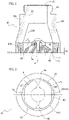
Figure 1 is a cross-sectional view of a preferred embodiment of the nozzle described herein; -
Figure 2 represents a view from beneath of the nozzle ofFigure 1 ; -
Figure 3 is a cross sectional view of a further embodiment of the nozzle described herein; -
Figure 4 represents at a schematic level the nozzle ofFigure 1 during a dispensing operation; and -
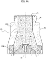
Figure 4A represents the nozzle ofFigure 1 after the dispensing operation has been interrupted. - In the ensuing description, various specific details are illustrated aimed at enabling an in-depth understanding of the embodiments. The embodiments may be provided without one or more of the specific details, or with other methods, components, or materials, etc. In other cases, known structures, materials, or operations are not illustrated or described in detail so that various aspects of the embodiment will not be obscured.
- The references used herein are provided merely for convenience and hence do not define the sphere of protection or the scope of the embodiments.
- As anticipated above, the present invention regards a nozzle for dispensing a flowable foodstuff product, in particular in the liquid or semi-liquid state.
- The nozzle described herein has been obtained specifically for dispensing foodstuff creams. In any case, the nozzle described herein may be advantageously used also for other applications. The applications may regard both Newtonian and non-Newtonian fluids.
- Preferably, the nozzle described herein is designed for dispensing foodstuff products on industrial production lines, for example for filling containers or else for filling products that are to be filled.
- With reference to
Figures 1 and 2 , the nozzle described herein, designated as a whole by thereference number 10, comprises amain module 20, which has an inlet opening 21, an outlet opening 22, and aduct 23 that connects the inlet opening 21 to the outlet opening 22. - Moreover, the
nozzle 10 comprises asecondary module 40, which is mounted within theduct 23 and at the outlet opening 22. Themodule 40 may be fixed to themodule 20 according to known modalities (not illustrated herein). - The
main module 20 defines a reference axis R along which theduct 23 extends longitudinally. - The
duct 23 has a cross section - orthogonal to the reference axis R - increasing in the direction from the inlet opening 21 to the outlet opening 22. In particular, preferably theduct 23 has anintermediate stretch 23A having a frustoconical shape, which is oriented so as to define a cross section increasing in the direction from the inlet opening 21 to the outlet opening 22. - The
main module 20 further comprises anouter portion 24 provided for connection to a dispensing apparatus of a conventional type. Theportion 24 may, for example, be threaded. A generic dispensing apparatus is provided with a system for supply of the product that comprises a flow-generating device, for example a pump, and at least one duct for carrying the product to a dispensing nozzle. Via theportion 24 thenozzle 10 can be connected to the aforesaid duct. - The
main module 20 has a substantially cylindricalinner surface 25, the geometrical axis of which coincides with the reference axis R and which delimits the outlet opening 22. - The
secondary module 40 has, in turn, anouter surface 41 that faces theinner surface 25. - Between the two
surfaces delivery mouth 60 that has an annular shape and extends around the reference axis R. Preferably, thedelivery mouth 60 has a cylindrical geometry; i.e., the section of flow defined thereby does not vary along the reference axis R. - In general, the
delivery mouth 60 generates a flow F of product that distributes around the reference axis R according to a tubular conformation (Figure 4 ). - Incidentally, it should be noted that the two
modules module 20 comprises anouter body 20A and aninsert 20B designed to define theinner surface 25 and to fix thesecondary module 40. - In alternative embodiments, the
nozzle 10 may, instead, comprise a single body having the configuration illustrated above, characterized by the inlet opening 21, theduct 23, the outlet opening 22, and thedelivery mouth 60. - According to an important characteristic of the nozzle described herein, the
delivery mouth 60 defines a section of flow having a width - measured in a radial direction with respect to the reference axis R - that is variable around the reference axis R so as to define, around the reference axis R, at least onefirst region 61 having a width L1, and at least onesecond region 62 having a width L2 greater than the width L1. - In the embodiment illustrated in
Figures 1 and 2 , identified along the development of thedelivery mouth 60 around the reference axis R are fourregions 61 spaced apart by asmany regions 62. Theindividual regions 61 are each delimited by the cylindricalinner surface 25 and acylindrical portion 41A of theouter surface 41, the geometrical axis of which coincides with the reference axis R. - On the other hand, each
region 62 is delimited by theinner surface 25 and by acorresponding plane portion 41B of theouter surface 41, which is parallel to the reference axis R. Theregions 62 hence have a variable width L2 that reaches the maximum value L2 (MAX) . - Moreover, preferably the
delivery mouth 60 has a height - measured in a direction parallel to the reference axis R - that is variable around the reference axis R in a way proportional to the width of themouth 60 itself so as to maintain a rate of the flow that passes through themouth 60 that is substantially constant along the entire development of the mouth around the reference axis R. - Preferably, the relation between the height and the width of the
mouth 60 is given by the following ratio:
- In general, the
regions 62 hence have a height H2 greater than the height H1 of theregions 61. - With reference to
Figure 1 , to obtain the configuration indicated, theplane portions 41B have a greater extension along the reference axis R than do thecylindrical portions 41A. - Thanks to the characteristics described above, the
delivery mouth 60 provides a flow F of product that presents thickened localized areas F1, in the delivery regions 62 (Figure 4 ). - The present applicant has been able to note that the localized thickening of the flow of product favours maintenance by the latter of the tubular shape throughout the duration of the dispensing operation even when delivery occurs at a high speed.
- In this regard, in the known solutions, in these conditions, the tubular flow can collapse transversely turning into an empty cone that remains in the final dispensing phase until it brings about dripping of the product.
- In the solution described herein, instead, the thickened areas of the flow of product increase the radial stiffness thereof, and the flow is hence able to maintain the tubular shape also in the final instants of the dispensing operation and also in the case of high-speed delivery.
- As represented schematically in
Figure 4A , the product that, after interruption of dispensing, remains on the nozzle thus maintains an arrangement along thedelivery mouth 60, and hence surface forces act thereon that are able to withhold it, thus preventing dripping of the product. - To return to
Figure 1 , thesecondary module 40 has, above theouter surface 41, aconical surface 42, the geometrical axis of which coincides with the reference axis R and which faces the inlet opening 21 so as to determine, together with theinner surface 25, a section of flow decreasing towards thedelivery mouth 60. As a whole, the conicity of thesurface 42 can be selected as a function of the desired fluid-dynamic conditions for flow of the product. Moreover, thesurface 42 may present variations of conicity so as to be radiused to thecylindrical portions 41A of theouter surface 41; in the example illustrated, thesurface 42 has, in particular, bottom portions with less pronounced conicity (see the angle α) that connect theportions 41A with height H1 to regions of thesurface 42 above the height H2 of theportions 41B. - According to a possible variant, the configuration described above of the
delivery mouth 60 may also be obtained by envisaging a reversal of characteristics between thesurfaces outer surface 41 and aninner surface 25 defined by an alternation of cylindrical portions and plane portions. - In any case, it is likewise possible to envisage other configurations and/or constructional modalities for the
delivery mouth 60. For instance, theregions 62 of width L2 may be delimited, instead of by plane portions, by hollow portions, thus increasing further the difference between the widths L1, L2 of theregions regions 62 may present a section of different shape with respect to the one illustrated, for example a circular section, an elliptical section, a rectangular section, etc. - With reference now to
Figure 3 , the embodiment illustrated therein differs from the one described previously in that thedelivery mouth 60 has an extremely reduced height H. In this case, thenozzle 10 presents at the mouth 60 a concentrated pressure drop so that the rate of the flow at outlet does not vary as the width of themouth 60 varies between thevarious regions regions - Of course, without prejudice to the principle of the invention, the details of construction and the embodiments may vary, even significantly, with respect to what has been illustrated purely by way of non-limiting example, without thereby departing from the scope of the invention, as defined by the annexed claims.
Claims (9)
- A nozzle for dispensing a flowable foodstuff product, in particular a foodstuff cream,comprising an inlet opening (21), an outlet opening (22) and a duct (23) that connects the inlet opening (21) with the outlet opening (22);wherein the outlet opening (22) is delimited by a first surface (25), the nozzle comprising a second surface (41) facing the first surface (25),between the first surface (25) and the second surface (41) there being defined a delivery mouth (60) having an annular shape, which extends around a reference axis (R) ;during operation said mouth (60) delivering a flow of product having a tubular shape,said nozzle (10) being characterized in that said first surface (25) and said second surface (41) are shaped in such a way that the delivery mouth (60) defines a section of flow, in a plane transverse to the reference axis (R), which has a width (L1, L2) variable around the reference axis (R), to define, around the reference axis (R), at least one first region (61) having a first width (L1) and at least one second region (62) having a second width (L2) greater than the first width (L1), so as to define, during operation, a flow of product having at least one thickened localized area that is delivered through the second region (62) of the delivery mouth (60).
- The nozzle according to Claim 1, wherein the first and second surfaces (25, 41) are shaped in such a way that the delivery mouth (60) has a variable height around the reference axis (R) for maintaining, during operation, a rate of the product delivered that is constant along the entire extension of the delivery mouth (60) around the reference axis (R).
- The nozzle according to Claim 1 or Claim 2, wherein the first and second surfaces (25, 41) are shaped so that the first region (61) has a first height (HI) and the second region (62) has a second height (H2) greater than the first height (HI).
- The nozzle according to any one of the preceding claims, wherein the first and second surfaces (25, 41) are parallel to the reference axis (R).
- The nozzle according to Claim 1 or Claim 2, wherein either the first or the second surface (25) is cylindrical and its geometrical axis coincides with the reference axis (R), and wherein either the second or the first surface (41) has at least one first cylindrical portion (41A), the geometrical axis of which coincides with the reference axis (R),between the cylindrical surface and the first cylindrical portion there being defined the first region (61) of the delivery mouth (60); andwherein the second or first surface (41) has at least one second portion that is plane (41B) or that in any case deviates from the cylindrical conformation of the first portion, towards the reference axis (R), to define the second width (L2) greater than the first width (L1),between the cylindrical surface and the second portion there being defined the at least one second region (62) of the delivery mouth (60).
- The nozzle according to any one of the preceding claims, comprising a conical or frustoconical surface (42) set over the second surface (41), the first surface (25) and the conical or frustoconical surface (42) defining an annular flow section decreasing in the direction from the inlet opening (21) to the outlet opening (22).
- The nozzle according to any one of the preceding claims, comprising:- a main module (20), defining the inlet opening (21), the outlet opening (22), and the duct (23) that connects the inlet opening (21) to the outlet opening (22) ;- an inner surface (25) of the main module defining the first surface (25); and- a second module (40), mounted within the duct (23) and at the outlet opening (22),
an outer surface (41) of the second module (40) that faces the inner surface (25) of the main module (20) defining the second surface (41). - A method for delivering a flowable foodstuff product, in particular a foodstuff cream, via a dispensing apparatus comprising a nozzle (10) according to any one of the preceding claims, which includes the steps of:- supplying a flow of product to the nozzle (10);- introducing the flow of product within the nozzle through the inlet opening (21);- conveying the flow of product through the duct (23); and- through the delivery mouth (60) delivering the flow of product in an arrangement where the product distributes around the reference axis (R) according to a tubular conformation;wherein the delivery step comprises:
defining on the tubular flow (F) of product delivered through the delivery mouth (60) at least one localized area (F1) that is thickened in a substantially radial direction with respect to the reference axis (R). - A method according to Claim 8, wherein the delivery step comprises delivering the product through the delivery mouth (60) at a substantially constant speed along the entire development of the delivery mouth (60) around the reference axis (R).
Applications Claiming Priority (1)
| Application Number | Priority Date | Filing Date | Title |
|---|---|---|---|
| IT202000031658 | 2020-12-21 |
Publications (2)
| Publication Number | Publication Date |
|---|---|
| EP4015405A1 true EP4015405A1 (en) | 2022-06-22 |
| EP4015405B1 EP4015405B1 (en) | 2023-09-06 |
Family
ID=75111677
Family Applications (1)
| Application Number | Title | Priority Date | Filing Date |
|---|---|---|---|
| EP21215013.0A Active EP4015405B1 (en) | 2020-12-21 | 2021-12-16 | Nozzle for dispensing a flowable foodstuff product |
Country Status (6)
| Country | Link |
|---|---|
| EP (1) | EP4015405B1 (en) |
| AU (1) | AU2021286399A1 (en) |
| BR (1) | BR102021025842A2 (en) |
| CA (1) | CA3142582A1 (en) |
| MX (1) | MX2021016162A (en) |
| PL (1) | PL4015405T3 (en) |
Cited By (1)
| Publication number | Priority date | Publication date | Assignee | Title |
|---|---|---|---|---|
| CN116281814A (en) * | 2022-12-23 | 2023-06-23 | 苏州瑞明香氛科技股份有限公司 | A dynamic display intelligent liquid plus solid deployment compound detection filling system |
Citations (3)
| Publication number | Priority date | Publication date | Assignee | Title |
|---|---|---|---|---|
| GB189999A (en) * | 1921-12-03 | 1922-12-14 | Arthur Smith | Improvements relating to machines for charging receptacles with powdered or like materials |
| JPH1179102A (en) * | 1997-09-10 | 1999-03-23 | Asahi Chem Ind Co Ltd | Viscous liquid supply method and viscous liquid supply nozzle |
| US20040118480A1 (en) * | 2001-03-13 | 2004-06-24 | Cyrille Durand | Filling spout for an umbrella-shaped jet |
-
2021
- 2021-12-16 PL PL21215013.0T patent/PL4015405T3/en unknown
- 2021-12-16 EP EP21215013.0A patent/EP4015405B1/en active Active
- 2021-12-16 CA CA3142582A patent/CA3142582A1/en active Pending
- 2021-12-17 MX MX2021016162A patent/MX2021016162A/en unknown
- 2021-12-17 AU AU2021286399A patent/AU2021286399A1/en active Pending
- 2021-12-20 BR BR102021025842-0A patent/BR102021025842A2/en unknown
Patent Citations (3)
| Publication number | Priority date | Publication date | Assignee | Title |
|---|---|---|---|---|
| GB189999A (en) * | 1921-12-03 | 1922-12-14 | Arthur Smith | Improvements relating to machines for charging receptacles with powdered or like materials |
| JPH1179102A (en) * | 1997-09-10 | 1999-03-23 | Asahi Chem Ind Co Ltd | Viscous liquid supply method and viscous liquid supply nozzle |
| US20040118480A1 (en) * | 2001-03-13 | 2004-06-24 | Cyrille Durand | Filling spout for an umbrella-shaped jet |
Cited By (1)
| Publication number | Priority date | Publication date | Assignee | Title |
|---|---|---|---|---|
| CN116281814A (en) * | 2022-12-23 | 2023-06-23 | 苏州瑞明香氛科技股份有限公司 | A dynamic display intelligent liquid plus solid deployment compound detection filling system |
Also Published As
| Publication number | Publication date |
|---|---|
| MX2021016162A (en) | 2022-08-08 |
| AU2021286399A1 (en) | 2022-07-07 |
| BR102021025842A2 (en) | 2022-07-05 |
| EP4015405B1 (en) | 2023-09-06 |
| PL4015405T3 (en) | 2024-09-09 |
| CA3142582A1 (en) | 2022-06-21 |
Similar Documents
| Publication | Publication Date | Title |
|---|---|---|
| US4607764A (en) | Fluent product extraction system | |
| USRE36377E (en) | Collapsible container | |
| US8231025B2 (en) | Dispensing process using tamper evident fitment assembly for a container | |
| EP3094590B1 (en) | Container-processing machine for processing containers | |
| US9511986B2 (en) | Filling element and filling system | |
| EP4015405B1 (en) | Nozzle for dispensing a flowable foodstuff product | |
| CA2911467C (en) | A process for coating containers | |
| US20060237563A1 (en) | Fluid discharge nozzle | |
| EP0144925B1 (en) | Packaging system | |
| EP0199538A1 (en) | Fluid flow nozzle | |
| EP0974548B1 (en) | Method and tank for dispensing under gravity liquid substances into containers | |
| EP2825498A1 (en) | An adaptor for use with a valve fitment for dispensing fluids | |
| AU2014317410A1 (en) | Device for flow rate control | |
| US20110163121A1 (en) | Method and system for volumetric displacement | |
| US8020590B2 (en) | Nozzle for filling a container with at least two viscous materials | |
| US20200346241A1 (en) | Filling flow divider | |
| RU2847359C2 (en) | Nozzle for distributing a fluid food product and method for supplying a fluid food product | |
| US3351250A (en) | Valve for viscous fluids | |
| US4491159A (en) | High speed liquid dispenser | |
| DE4416089A1 (en) | Arrangement for dispensing highly viscous liquids or liquids with high solid content | |
| EP2479113B1 (en) | Method and dispenser head for feeding a liquid product into a container | |
| US10799636B2 (en) | Filling needle for dispensing a pharmaceutical liquid into a container, and filling device | |
| CN207175437U (en) | Filling changing nozzle | |
| CN113795456A (en) | Fill valve for filling containers with pourable product | |
| WO1994021550A1 (en) | Closure for fluid containers |
Legal Events
| Date | Code | Title | Description |
|---|---|---|---|
| PUAI | Public reference made under article 153(3) epc to a published international application that has entered the european phase |
Free format text: ORIGINAL CODE: 0009012 |
|
| STAA | Information on the status of an ep patent application or granted ep patent |
Free format text: STATUS: THE APPLICATION HAS BEEN PUBLISHED |
|
| AK | Designated contracting states |
Kind code of ref document: A1 Designated state(s): AL AT BE BG CH CY CZ DE DK EE ES FI FR GB GR HR HU IE IS IT LI LT LU LV MC MK MT NL NO PL PT RO RS SE SI SK SM TR |
|
| STAA | Information on the status of an ep patent application or granted ep patent |
Free format text: STATUS: REQUEST FOR EXAMINATION WAS MADE |
|
| 17P | Request for examination filed |
Effective date: 20221128 |
|
| RBV | Designated contracting states (corrected) |
Designated state(s): AL AT BE BG CH CY CZ DE DK EE ES FI FR GB GR HR HU IE IS IT LI LT LU LV MC MK MT NL NO PL PT RO RS SE SI SK SM TR |
|
| GRAP | Despatch of communication of intention to grant a patent |
Free format text: ORIGINAL CODE: EPIDOSNIGR1 |
|
| STAA | Information on the status of an ep patent application or granted ep patent |
Free format text: STATUS: GRANT OF PATENT IS INTENDED |
|
| RIC1 | Information provided on ipc code assigned before grant |
Ipc: B67C 3/28 20060101ALI20230310BHEP Ipc: B67C 3/26 20060101ALI20230310BHEP Ipc: B65B 39/00 20060101AFI20230310BHEP |
|
| INTG | Intention to grant announced |
Effective date: 20230331 |
|
| GRAS | Grant fee paid |
Free format text: ORIGINAL CODE: EPIDOSNIGR3 |
|
| GRAA | (expected) grant |
Free format text: ORIGINAL CODE: 0009210 |
|
| STAA | Information on the status of an ep patent application or granted ep patent |
Free format text: STATUS: THE PATENT HAS BEEN GRANTED |
|
| AK | Designated contracting states |
Kind code of ref document: B1 Designated state(s): AL AT BE BG CH CY CZ DE DK EE ES FI FR GB GR HR HU IE IS IT LI LT LU LV MC MK MT NL NO PL PT RO RS SE SI SK SM TR |
|
| REG | Reference to a national code |
Ref country code: GB Ref legal event code: FG4D |
|
| REG | Reference to a national code |
Ref country code: CH Ref legal event code: EP |
|
| REG | Reference to a national code |
Ref country code: IE Ref legal event code: FG4D |
|
| REG | Reference to a national code |
Ref country code: DE Ref legal event code: R096 Ref document number: 602021004952 Country of ref document: DE |
|
| P01 | Opt-out of the competence of the unified patent court (upc) registered |
Effective date: 20231010 |
|
| RAP2 | Party data changed (patent owner data changed or rights of a patent transferred) |
Owner name: SOREMARTEC S.A. |
|
| REG | Reference to a national code |
Ref country code: DE Ref legal event code: R081 Ref document number: 602021004952 Country of ref document: DE Owner name: SOREMARTEC S.A., LU Free format text: FORMER OWNERS: POLITECNICO DI TORINO, TORINO, IT; SOREMARTEC S.A., SENNINGERBERG, LU |
|
| REG | Reference to a national code |
Ref country code: LT Ref legal event code: MG9D |
|
| REG | Reference to a national code |
Ref country code: NL Ref legal event code: MP Effective date: 20230906 |
|
| PG25 | Lapsed in a contracting state [announced via postgrant information from national office to epo] |
Ref country code: GR Free format text: LAPSE BECAUSE OF FAILURE TO SUBMIT A TRANSLATION OF THE DESCRIPTION OR TO PAY THE FEE WITHIN THE PRESCRIBED TIME-LIMIT Effective date: 20231207 |
|
| PG25 | Lapsed in a contracting state [announced via postgrant information from national office to epo] |
Ref country code: SE Free format text: LAPSE BECAUSE OF FAILURE TO SUBMIT A TRANSLATION OF THE DESCRIPTION OR TO PAY THE FEE WITHIN THE PRESCRIBED TIME-LIMIT Effective date: 20230906 Ref country code: RS Free format text: LAPSE BECAUSE OF FAILURE TO SUBMIT A TRANSLATION OF THE DESCRIPTION OR TO PAY THE FEE WITHIN THE PRESCRIBED TIME-LIMIT Effective date: 20230906 Ref country code: NO Free format text: LAPSE BECAUSE OF FAILURE TO SUBMIT A TRANSLATION OF THE DESCRIPTION OR TO PAY THE FEE WITHIN THE PRESCRIBED TIME-LIMIT Effective date: 20231206 Ref country code: LV Free format text: LAPSE BECAUSE OF FAILURE TO SUBMIT A TRANSLATION OF THE DESCRIPTION OR TO PAY THE FEE WITHIN THE PRESCRIBED TIME-LIMIT Effective date: 20230906 Ref country code: LT Free format text: LAPSE BECAUSE OF FAILURE TO SUBMIT A TRANSLATION OF THE DESCRIPTION OR TO PAY THE FEE WITHIN THE PRESCRIBED TIME-LIMIT Effective date: 20230906 Ref country code: HR Free format text: LAPSE BECAUSE OF FAILURE TO SUBMIT A TRANSLATION OF THE DESCRIPTION OR TO PAY THE FEE WITHIN THE PRESCRIBED TIME-LIMIT Effective date: 20230906 Ref country code: GR Free format text: LAPSE BECAUSE OF FAILURE TO SUBMIT A TRANSLATION OF THE DESCRIPTION OR TO PAY THE FEE WITHIN THE PRESCRIBED TIME-LIMIT Effective date: 20231207 Ref country code: FI Free format text: LAPSE BECAUSE OF FAILURE TO SUBMIT A TRANSLATION OF THE DESCRIPTION OR TO PAY THE FEE WITHIN THE PRESCRIBED TIME-LIMIT Effective date: 20230906 |
|
| REG | Reference to a national code |
Ref country code: AT Ref legal event code: MK05 Ref document number: 1608253 Country of ref document: AT Kind code of ref document: T Effective date: 20230906 |
|
| PG25 | Lapsed in a contracting state [announced via postgrant information from national office to epo] |
Ref country code: NL Free format text: LAPSE BECAUSE OF FAILURE TO SUBMIT A TRANSLATION OF THE DESCRIPTION OR TO PAY THE FEE WITHIN THE PRESCRIBED TIME-LIMIT Effective date: 20230906 |
|
| PG25 | Lapsed in a contracting state [announced via postgrant information from national office to epo] |
Ref country code: IS Free format text: LAPSE BECAUSE OF FAILURE TO SUBMIT A TRANSLATION OF THE DESCRIPTION OR TO PAY THE FEE WITHIN THE PRESCRIBED TIME-LIMIT Effective date: 20240106 |
|
| PG25 | Lapsed in a contracting state [announced via postgrant information from national office to epo] |
Ref country code: AT Free format text: LAPSE BECAUSE OF FAILURE TO SUBMIT A TRANSLATION OF THE DESCRIPTION OR TO PAY THE FEE WITHIN THE PRESCRIBED TIME-LIMIT Effective date: 20230906 |
|
| PG25 | Lapsed in a contracting state [announced via postgrant information from national office to epo] |
Ref country code: ES Free format text: LAPSE BECAUSE OF FAILURE TO SUBMIT A TRANSLATION OF THE DESCRIPTION OR TO PAY THE FEE WITHIN THE PRESCRIBED TIME-LIMIT Effective date: 20230906 |
|
| PG25 | Lapsed in a contracting state [announced via postgrant information from national office to epo] |
Ref country code: SM Free format text: LAPSE BECAUSE OF FAILURE TO SUBMIT A TRANSLATION OF THE DESCRIPTION OR TO PAY THE FEE WITHIN THE PRESCRIBED TIME-LIMIT Effective date: 20230906 Ref country code: RO Free format text: LAPSE BECAUSE OF FAILURE TO SUBMIT A TRANSLATION OF THE DESCRIPTION OR TO PAY THE FEE WITHIN THE PRESCRIBED TIME-LIMIT Effective date: 20230906 Ref country code: IS Free format text: LAPSE BECAUSE OF FAILURE TO SUBMIT A TRANSLATION OF THE DESCRIPTION OR TO PAY THE FEE WITHIN THE PRESCRIBED TIME-LIMIT Effective date: 20240106 Ref country code: ES Free format text: LAPSE BECAUSE OF FAILURE TO SUBMIT A TRANSLATION OF THE DESCRIPTION OR TO PAY THE FEE WITHIN THE PRESCRIBED TIME-LIMIT Effective date: 20230906 Ref country code: EE Free format text: LAPSE BECAUSE OF FAILURE TO SUBMIT A TRANSLATION OF THE DESCRIPTION OR TO PAY THE FEE WITHIN THE PRESCRIBED TIME-LIMIT Effective date: 20230906 Ref country code: CZ Free format text: LAPSE BECAUSE OF FAILURE TO SUBMIT A TRANSLATION OF THE DESCRIPTION OR TO PAY THE FEE WITHIN THE PRESCRIBED TIME-LIMIT Effective date: 20230906 Ref country code: AT Free format text: LAPSE BECAUSE OF FAILURE TO SUBMIT A TRANSLATION OF THE DESCRIPTION OR TO PAY THE FEE WITHIN THE PRESCRIBED TIME-LIMIT Effective date: 20230906 Ref country code: PT Free format text: LAPSE BECAUSE OF FAILURE TO SUBMIT A TRANSLATION OF THE DESCRIPTION OR TO PAY THE FEE WITHIN THE PRESCRIBED TIME-LIMIT Effective date: 20240108 Ref country code: SK Free format text: LAPSE BECAUSE OF FAILURE TO SUBMIT A TRANSLATION OF THE DESCRIPTION OR TO PAY THE FEE WITHIN THE PRESCRIBED TIME-LIMIT Effective date: 20230906 |
|
| REG | Reference to a national code |
Ref country code: DE Ref legal event code: R097 Ref document number: 602021004952 Country of ref document: DE |
|
| PG25 | Lapsed in a contracting state [announced via postgrant information from national office to epo] |
Ref country code: DK Free format text: LAPSE BECAUSE OF FAILURE TO SUBMIT A TRANSLATION OF THE DESCRIPTION OR TO PAY THE FEE WITHIN THE PRESCRIBED TIME-LIMIT Effective date: 20230906 |
|
| PLBE | No opposition filed within time limit |
Free format text: ORIGINAL CODE: 0009261 |
|
| STAA | Information on the status of an ep patent application or granted ep patent |
Free format text: STATUS: NO OPPOSITION FILED WITHIN TIME LIMIT |
|
| PG25 | Lapsed in a contracting state [announced via postgrant information from national office to epo] |
Ref country code: DK Free format text: LAPSE BECAUSE OF FAILURE TO SUBMIT A TRANSLATION OF THE DESCRIPTION OR TO PAY THE FEE WITHIN THE PRESCRIBED TIME-LIMIT Effective date: 20230906 Ref country code: SI Free format text: LAPSE BECAUSE OF FAILURE TO SUBMIT A TRANSLATION OF THE DESCRIPTION OR TO PAY THE FEE WITHIN THE PRESCRIBED TIME-LIMIT Effective date: 20230906 |
|
| 26N | No opposition filed |
Effective date: 20240607 |
|
| PG25 | Lapsed in a contracting state [announced via postgrant information from national office to epo] |
Ref country code: LU Free format text: LAPSE BECAUSE OF NON-PAYMENT OF DUE FEES Effective date: 20231216 |
|
| PG25 | Lapsed in a contracting state [announced via postgrant information from national office to epo] |
Ref country code: MC Free format text: LAPSE BECAUSE OF FAILURE TO SUBMIT A TRANSLATION OF THE DESCRIPTION OR TO PAY THE FEE WITHIN THE PRESCRIBED TIME-LIMIT Effective date: 20230906 |
|
| REG | Reference to a national code |
Ref country code: BE Ref legal event code: MM Effective date: 20231231 |
|
| PG25 | Lapsed in a contracting state [announced via postgrant information from national office to epo] |
Ref country code: MC Free format text: LAPSE BECAUSE OF FAILURE TO SUBMIT A TRANSLATION OF THE DESCRIPTION OR TO PAY THE FEE WITHIN THE PRESCRIBED TIME-LIMIT Effective date: 20230906 Ref country code: LU Free format text: LAPSE BECAUSE OF NON-PAYMENT OF DUE FEES Effective date: 20231216 |
|
| REG | Reference to a national code |
Ref country code: IE Ref legal event code: MM4A |
|
| PG25 | Lapsed in a contracting state [announced via postgrant information from national office to epo] |
Ref country code: IE Free format text: LAPSE BECAUSE OF NON-PAYMENT OF DUE FEES Effective date: 20231216 |
|
| PG25 | Lapsed in a contracting state [announced via postgrant information from national office to epo] |
Ref country code: BE Free format text: LAPSE BECAUSE OF NON-PAYMENT OF DUE FEES Effective date: 20231231 |
|
| PG25 | Lapsed in a contracting state [announced via postgrant information from national office to epo] |
Ref country code: IE Free format text: LAPSE BECAUSE OF NON-PAYMENT OF DUE FEES Effective date: 20231216 Ref country code: BE Free format text: LAPSE BECAUSE OF NON-PAYMENT OF DUE FEES Effective date: 20231231 |
|
| PG25 | Lapsed in a contracting state [announced via postgrant information from national office to epo] |
Ref country code: BG Free format text: LAPSE BECAUSE OF FAILURE TO SUBMIT A TRANSLATION OF THE DESCRIPTION OR TO PAY THE FEE WITHIN THE PRESCRIBED TIME-LIMIT Effective date: 20230906 |
|
| PG25 | Lapsed in a contracting state [announced via postgrant information from national office to epo] |
Ref country code: BG Free format text: LAPSE BECAUSE OF FAILURE TO SUBMIT A TRANSLATION OF THE DESCRIPTION OR TO PAY THE FEE WITHIN THE PRESCRIBED TIME-LIMIT Effective date: 20230906 |
|
| PG25 | Lapsed in a contracting state [announced via postgrant information from national office to epo] |
Ref country code: CY Free format text: LAPSE BECAUSE OF FAILURE TO SUBMIT A TRANSLATION OF THE DESCRIPTION OR TO PAY THE FEE WITHIN THE PRESCRIBED TIME-LIMIT; INVALID AB INITIO Effective date: 20211216 |
|
| REG | Reference to a national code |
Ref country code: CH Ref legal event code: PL |
|
| PG25 | Lapsed in a contracting state [announced via postgrant information from national office to epo] |
Ref country code: CH Free format text: LAPSE BECAUSE OF NON-PAYMENT OF DUE FEES Effective date: 20241231 |
|
| PGFP | Annual fee paid to national office [announced via postgrant information from national office to epo] |
Ref country code: DE Payment date: 20251126 Year of fee payment: 5 |
|
| PGFP | Annual fee paid to national office [announced via postgrant information from national office to epo] |
Ref country code: IT Payment date: 20251119 Year of fee payment: 5 |
|
| PGFP | Annual fee paid to national office [announced via postgrant information from national office to epo] |
Ref country code: FR Payment date: 20251120 Year of fee payment: 5 |
|
| PGFP | Annual fee paid to national office [announced via postgrant information from national office to epo] |
Ref country code: TR Payment date: 20251125 Year of fee payment: 5 |
|
| PGFP | Annual fee paid to national office [announced via postgrant information from national office to epo] |
Ref country code: PL Payment date: 20251204 Year of fee payment: 5 |
|
| PG25 | Lapsed in a contracting state [announced via postgrant information from national office to epo] |
Ref country code: HU Free format text: LAPSE BECAUSE OF FAILURE TO SUBMIT A TRANSLATION OF THE DESCRIPTION OR TO PAY THE FEE WITHIN THE PRESCRIBED TIME-LIMIT; INVALID AB INITIO Effective date: 20211216 |