EP4015382A1 - Sliding latch for galley bay doors - Google Patents
Sliding latch for galley bay doors Download PDFInfo
- Publication number
- EP4015382A1 EP4015382A1 EP21214885.2A EP21214885A EP4015382A1 EP 4015382 A1 EP4015382 A1 EP 4015382A1 EP 21214885 A EP21214885 A EP 21214885A EP 4015382 A1 EP4015382 A1 EP 4015382A1
- Authority
- EP
- European Patent Office
- Prior art keywords
- slider
- door
- galley
- housing
- plate
- Prior art date
- Legal status (The legal status is an assumption and is not a legal conclusion. Google has not performed a legal analysis and makes no representation as to the accuracy of the status listed.)
- Granted
Links
Images


Classifications
-
- E—FIXED CONSTRUCTIONS
- E05—LOCKS; KEYS; WINDOW OR DOOR FITTINGS; SAFES
- E05C—BOLTS OR FASTENING DEVICES FOR WINGS, SPECIALLY FOR DOORS OR WINDOWS
- E05C1/00—Fastening devices with bolts moving rectilinearly
- E05C1/02—Fastening devices with bolts moving rectilinearly without latching action
- E05C1/04—Fastening devices with bolts moving rectilinearly without latching action with operating handle or equivalent member rigid with the bolt
-
- B—PERFORMING OPERATIONS; TRANSPORTING
- B64—AIRCRAFT; AVIATION; COSMONAUTICS
- B64D—EQUIPMENT FOR FITTING IN OR TO AIRCRAFT; FLIGHT SUITS; PARACHUTES; ARRANGEMENT OR MOUNTING OF POWER PLANTS OR PROPULSION TRANSMISSIONS IN AIRCRAFT
- B64D11/00—Passenger or crew accommodation; Flight-deck installations not otherwise provided for
- B64D11/04—Galleys
-
- E—FIXED CONSTRUCTIONS
- E05—LOCKS; KEYS; WINDOW OR DOOR FITTINGS; SAFES
- E05C—BOLTS OR FASTENING DEVICES FOR WINGS, SPECIALLY FOR DOORS OR WINDOWS
- E05C1/00—Fastening devices with bolts moving rectilinearly
- E05C1/004—Fastening devices with bolts moving rectilinearly parallel to the surface on which the fastener is mounted
-
- B—PERFORMING OPERATIONS; TRANSPORTING
- B64—AIRCRAFT; AVIATION; COSMONAUTICS
- B64D—EQUIPMENT FOR FITTING IN OR TO AIRCRAFT; FLIGHT SUITS; PARACHUTES; ARRANGEMENT OR MOUNTING OF POWER PLANTS OR PROPULSION TRANSMISSIONS IN AIRCRAFT
- B64D11/00—Passenger or crew accommodation; Flight-deck installations not otherwise provided for
- B64D11/0007—Devices specially adapted for food or beverage distribution services
Definitions
- the slider and slider plate can be configured to displace at least 22 mm between the first and second positions.
- the slider and slider plate can be configured to displace at least 30 mm between the first and second positions.
- the slider plate can be slidingly seated in a channel of the housing for guiding the slider plate without a guide separate from the housing.
- the channel can be open on both ends of the housing so in the second position, a portion of the slider plate extends beyond the channel.
- a method comprises securing contents in a galley trolley with a door on the galley trolley and providing secondary retention for the contents in the galley trolley by closing the galley trolley inside a galley bay with a door of the galley bay.
- the door of the galley bay includes a slider for securing the galley bay door in a closed position. Securing the galley bay door in the closed position can include sliding the slider at least 30 mm.
- the door of the galley bay can be a first door and can further include a second door of the galley bay. Securing the galley bay door in a closed position can include securing the first and second galley bay doors together.
- the strike plate 128 can be mounted to the door frame 120 in a position that aligns the slider plate 114 with an opening 130 of the strike plate 128. While the slider housing 102 and strike plate 128 may be mounted to the galley door 104 and door frame 120 respectively in any suitable position, the slider housing 102 and the strike plate 128 should be placed in the same position with respect to each other so that when the slider 106 is in the first position, the slider plate 114 may properly engage with the opening 130 with the strike plate 128 such as shown in Fig. 4 .
Landscapes
- Engineering & Computer Science (AREA)
- Mechanical Engineering (AREA)
- Aviation & Aerospace Engineering (AREA)
- Refrigerator Housings (AREA)
Abstract
Description
- The disclosure relates generally to aircraft galley equipment, and more particularly to securing contents of galley trolleys.
- Trolley doors do not have a secondary retention, such as a long turn button, therefore galley trolley-bay doors must traditionally act as the secondary retention of trolley contents. However, traditionally there is no substantiation of the requirement for secondary retention of the trolley contents by the trolley bay door.
- The conventional techniques have been considered satisfactory for their intended purpose. However, there is an ever present need for improved systems and methods for retention of trolley contents. This disclosure provides a solution for this need.
- A galley bay door system comprises a slider housing configured to be mounted in a galley bay door. The system also includes a slider mounted in the slider housing and configured for sliding movement relative to the slider housing and a slider plate mounted to the slider for movement together with the slider.
- The slider can be configured to slide between a first and second position. In the first position of the slider, the slider plate can extend beyond the housing to secure a galley bay door in a closed state. In the second position of the slider, the slider plate can be withdrawn into the housing relative to the first position to allow opening the galley bay door from the closed state.
- The system can further include the galley bay door and the slider housing can be mounted in the gallery bay door. They system can include a door frame and the galley bay door can be hingedly mounted to the door frame. The door frame can include a strike plate configured to receive the slider plate in the first position of the slider. The strike plate can be mounted to the door frame in a position that aligns the slider plate with an opening of the strike plate for securing the galley bay door to the door frame with the slider in the first position.
- In embodiments, the system can also include a first galley bay door where the slider housing can be mounted in the first gallery bay door, a second galley bay door. A door frame may be included where the first and second galley bay doors can each be hingedly mounted to the door frame as a double door pair. The second galley bay door can include a strike plate configured to receive the slider plate in the first position of the slider. The strike plate can be mounted to the second galley bay door in a position that aligns the slider plate with an opening of the strike plate for securing the first galley bay door to the second galley bay door with the slider in the first position.
- The slider and slider plate can be configured to displace at least 22 mm between the first and second positions. The slider and slider plate can be configured to displace at least 30 mm between the first and second positions. The slider plate can be slidingly seated in a channel of the housing for guiding the slider plate without a guide separate from the housing. The channel can be open on both ends of the housing so in the second position, a portion of the slider plate extends beyond the channel.
- The system can include a slider handle mounted to the slider for manual engagement to actuate the slider. The slider housing can include a dividing wall separating the slider from the slider handle. The slider handle can engage the slider through a slot in the dividing wall. A spacer block surrounding an outer periphery of the housing and a back plate mounted to the housing can also be included. The housing and back plate can be configured to clamp a galley bay door therebetween to mount the system to the galley bay door.
- A method comprises securing contents in a galley trolley with a door on the galley trolley and providing secondary retention for the contents in the galley trolley by closing the galley trolley inside a galley bay with a door of the galley bay. The door of the galley bay includes a slider for securing the galley bay door in a closed position. Securing the galley bay door in the closed position can include sliding the slider at least 30 mm. The door of the galley bay can be a first door and can further include a second door of the galley bay. Securing the galley bay door in a closed position can include securing the first and second galley bay doors together.
- These and other features of the systems and methods of the subject disclosure will become more readily apparent to those skilled in the art from the following detailed description taken in conjunction with the drawings.
- So that those skilled in the art to which the subject disclosure appertains will readily understand how to make and use the devices and methods of the subject disclosure without undue experimentation, embodiments thereof will be described in detail herein below with reference to certain figures, wherein:
-
Fig. 1 is a schematic view of an embodiment of a galley bay door system constructed in accordance with the present disclosure, showing from the outside a double galley bay door having a sliding locking system; -
Fig. 2 is a schematic perspective view of the sliding locking system ofFig. 1 ; -
Fig. 3 is a schematic view of the sliding locking system ofFig. 1 showing the locking system in a first position and a second position; -
Fig. 4 is a schematic interior view of the sliding locking system ofFig. 1 showing the locking system installed in a galley bay double door; -
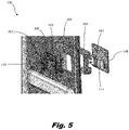
Fig. 5 is an exploded side perspective view of the locking system ofFig. 1 showing the assembly of the locking system within a galley door; and -
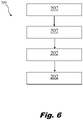
Fig. 6 is a schematic box diagram of a method in accordance with at least one aspect of this disclosure. - Reference will now be made to the drawings wherein like reference numerals identify similar structural features or aspects of the subject disclosure. For purposes of explanation and illustration, and not limitation, a partial view of an embodiment of a system in accordance with the disclosure is shown in
Fig. 1 and is designated generally byreference character 100. Other embodiments of systems in accordance with the disclosure, or aspects thereof, are provided inFigs. 2-6 , as will be described. The systems and methods described herein can be used to improve retention of trolley contents. - Referring to
Figs. 1-4 , a galleybay door system 100 can include aslider housing 102 configured to be mounted in agalley bay door 104. Thesystem 100 can also include aslider 106 mounted in theslider housing 102 and configured for sliding movement relative to theslider housing 102. For example, theslider housing 102 can include a dividingwall 108 separating theslider 104 from aslider handle 110. Theslider handle 110 can thus engage theslider 106 through aslot 112 in the dividingwall 108 for manual engagement to actuate theslider 106. Aslider plate 114 can be mounted to theslider 106 for movement together with theslider 106. As shown inFig. 3 , theslider plate 114 can be slidingly seated in achannel 122 of thehousing 102 for guiding theslider plate 114 between the first and second positions without an additional guide separate from thehousing 102. Further, the channel can be open on both ends of thehousing 102 so that in the second position, a portion of theslider plate 114 can extend beyond thechannel 122. Allowing theslider plate 114 to extend beyond the housing in the second position allows for a longer stroke of theslider 106 andslider plate 114 without increasing the size of thehousing 102, thereby reducing the overall size of thesystem 100. - The
slider housing 102 can be mounted in thegalley bay door 104 in any suitable position. Adoor frame 120 can be included such that thegalley bay door 104 can be hingedly mounted to the door frame 120 (e.g. via hinge 126). Thedoor frame 120 can include astrike plate 128 for receiving theslider plate 114 when theslider 106 is in the first position. Though not explicitly shown here, it should be appreciated that thestrike plate 128 can be mounted in thedoor frame 120 in the same or similar manner as a secondgalley bay door 132 as shown inFig. 4 , i.e. in a single-door system rather than the double door system shown. Thestrike plate 128 can be mounted to thedoor frame 120 in a position that aligns theslider plate 114 with an opening 130 of thestrike plate 128. While theslider housing 102 andstrike plate 128 may be mounted to thegalley door 104 anddoor frame 120 respectively in any suitable position, theslider housing 102 and thestrike plate 128 should be placed in the same position with respect to each other so that when theslider 106 is in the first position, theslider plate 114 may properly engage with the opening 130 with thestrike plate 128 such as shown inFig. 4 . - The
slider 106 can slide between a first position and a second position as shown by the arrow inFig. 3 (e.g. a first position can be an engaged or locked position and the second position can be a disengages or unlocked position). When theslider 106 is in the first position (e.g. locked), theslider plate 114 can extend beyond thehousing 102 to secure thegalley bay door 104 in a closed state. When theslider 106 is in the second position (e.g. unlocked), theslider plate 114 can be withdrawn into thehousing 102 relative to the first position to allow opening thegalley bay door 104 from the closed state. Theslider housing 102 can also contain detents 160,162 configured to receiverespective detent balls 164 on theslider plate 114. In the first position,detent balls 164 can engagedetents 160, and in the second position, thedetent balls 164 can engage withdetents 162. The detents 160,162 anddetent balls 164 are provided so that theslider 106 andslider plate 114 cannot move between the first and second position without sufficient force applied. For example, rattling or shaking of galley contents during flight or a turbulent event should not be able to dislodge theslider 106 andslider plate 114 from either position, but the force required should be such that flight staff may be able to move theslider 106 andslider plate 114 between the first and second positions relatively easily. - In embodiments such as shown in
Figs 1 and4 (e.g. for chilled double door compartments in the galley), thesystem 100 can also include a firstgalley bay door 104 and a secondgalley bay door 132, each can be hingeldy mounted to thedoor frame 120. Theslider housing 102 can be mounted in the firstgallery bay door 104, and thestrike plate 128 can be mounted in the secondgalley bay door 132 in a position that aligns with theslider housing 102 so that theslider plate 114 may properly engage with the opening 130 in thestrike plate 128 when theslider 106 is in the first position (e.g. as shown inFig. 4 ). - The
slider 106 andslider plate 114 can displace 22 mm between the first and second positions, however the displacement distance may be extended or reduced so that theslider 106 andslider plate 114 can be configured and adapted to displace the necessary distance of an already existing galley door system. A spacer block 168 (e.g. a machine block) can surround an outer periphery of thehousing 102 and can be mounted to thedoor 104, for example using any suitable adhesive. Aback plate 148 can be mounted to the housing 102 (e.g. by a plurality of fasteners 150), so that thehousing 102 andback plate 148 are configured to clamp a galley bay door therebetween to mount thesystem 100 to thegalley bay door 104. - Shown in
Fig. 6 , amethod 200 can include, atbox 202, securing contents in a galley trolley with a door on the galley trolley. At box 204, the method can include providing secondary retention for the contents in the galley trolley by closing the galley trolley inside a galley bay with a door of the galley bay. The door of the galley bay can a galleybay door system 100 as described above. Securing the galley bay door in the closed position can include, as shown at box 206, sliding the slider at least 22 mm. If the galley bay contains more than one door (e.g. doors 104 and 132), securing the galley bay door in a closed position can include securing the first and second galley bay doors together, as shown at box 208. - Conventional galley trolley doors do not have a secondary retention mechanism to keep the trolley doors closed, so the galley trolley-bay doors (e.g. doors 104,132) must act as means for secondary retention of trolley contents. Typically, galley bay doors have only a single locking mechanism for each door usually located near the top of the door. However, the galley bay doors need to be able to withstand up to or at least 500kg of force from the galley contents. Due to such force, the galley bay doors had a higher failure rate, particularly near the bottom of the door. The systems and methods disclosed herein provide a solution for this need.
- The methods and systems of the present disclosure as described above and shown in the drawings, therefore provide for an improved secondary locking mechanism having light weight design that can reduce the number of overall components needed for retention of trolley contents. While the apparatus and methods of the subject disclosure have been shown and described, those skilled in the art will readily appreciate that changes and/or modifications may be made thereto without departing from the scope of the invention as defined by the claims.
Claims (15)
- A galley bay door system comprising:a slider housing (102) configured to be mounted in a galley bay door (104);a slider (106) mounted in the slider housing and configured for sliding movement relative to the slider housing;a slider plate (114) mounted to the slider for movement together with the slider; andwherein the slider is configured to slide between a first and second position, wherein in the first position of the slider, the slider plate extends beyond the housing to secure a galley bay door in a closed state, and in the second position of the slider, the slider plate is withdrawn into housing relative to the first position to allow opening the galley bay door from the close state.
- The system as recited in claim 1, further comprising:the galley bay door (104), wherein the slider housing (102) is mounted in the gallery bay door; anda door frame (120), wherein the galley bay door is hingedly mounted to the door frame.
- The system as recited in claim 2, wherein the door frame includes a strike plate (128) configured to receive the slider plate (114) in the first position of the slider, wherein the strike plate is mounted to the door frame in a position that aligns the slider plate with an opening of the strike plate for securing the galley bay door to the door frame with the slider in the first position.
- The system as recited in claim 1, further comprising:a first galley bay door (104), wherein the slider housing is mounted in the first gallery bay door;a second galley bay door (132); anda door frame (120), wherein the first and second galley bay doors are each hingedly mounted to the door frame as a double door pair.
- The system as recited in claim 4, wherein the second galley bay door includes a strike plate (128) configured to receive the slider plate (114) in the first position of the slider (106), wherein the strike plate (128) is mounted to the second galley bay door in a position that aligns the slider plate with an opening of the strike plate for securing the first galley bay door to the second galley bay door with the slider in the first position.
- The system as recited in any preceding claim, wherein the slider (106) and slider plate (114) are configured to displace at least 22 mm between the first and second positions.
- The system as recited in any preceding claim, wherein the slider and slider plate are configured to displace at least 30 mm between the first and second positions.
- The system as recited in any preceding claim, wherein the slider plate (114) is slidingly seated in a channel (122) of the housing for guiding the slider plate without a guide separate from the housing.
- The system as recited in claim 8, wherein the channel is open on both ends of the housing so in the second position, a portion of the slider plate extends beyond the channel.
- The system as recited in any preceding claim, further comprising a slider handle (110) mounted to the slider for manual engagement to actuate the slider.
- The system as recited in claim 10, wherein the slider housing includes a dividing wall (108) separating the slider from the slider handle, wherein the slider handle engages the slider through a slot in the dividing wall.
- The system as recited in any preceding claim, further comprising:
a spacer block (168) surrounding an outer periphery of the housing; and
a back plate (148) mounted to the housing, wherein the housing and back plate are configured to clamp a galley bay door therebetween to mount the system to the galley bay door. - A method comprising:securing contents in a galley trolley with a door on the galley trolley; andproviding secondary retention for the contents in the galley trolley by closing the galley trolley inside a galley bay with a door of the galley bay, wherein the door of the galley bay includes a slider for securing the galley bay door in a closed position.
- The method as recited in claim 13, wherein securing the galley bay door in the closed position includes sliding the slider at least 22 mm.
- The method as recited in claim 13, wherein the door of the galley bay is a first door, and further comprising a second door of the galley bay, wherein securing the galley bay door in a closed position includes securing the first and second galley bay doors together.
Applications Claiming Priority (1)
| Application Number | Priority Date | Filing Date | Title |
|---|---|---|---|
| US17/122,561 US12320171B2 (en) | 2020-12-15 | 2020-12-15 | Sliding latch for galley bay doors |
Publications (2)
| Publication Number | Publication Date |
|---|---|
| EP4015382A1 true EP4015382A1 (en) | 2022-06-22 |
| EP4015382B1 EP4015382B1 (en) | 2025-10-29 |
Family
ID=79024290
Family Applications (1)
| Application Number | Title | Priority Date | Filing Date |
|---|---|---|---|
| EP21214885.2A Active EP4015382B1 (en) | 2020-12-15 | 2021-12-15 | Sliding latch for galley bay doors |
Country Status (2)
| Country | Link |
|---|---|
| US (1) | US12320171B2 (en) |
| EP (1) | EP4015382B1 (en) |
Families Citing this family (2)
| Publication number | Priority date | Publication date | Assignee | Title |
|---|---|---|---|---|
| US12313265B2 (en) * | 2021-01-19 | 2025-05-27 | B/E Aerospace, Inc. | Galley insert doors |
| US12365464B2 (en) * | 2023-03-06 | 2025-07-22 | Airbus (S.A.S.) | Galley for aircraft comprising a trolley locking system |
Citations (4)
| Publication number | Priority date | Publication date | Assignee | Title |
|---|---|---|---|---|
| EP1132556A2 (en) * | 2000-03-06 | 2001-09-12 | Jamco Corporation | Door latch |
| US6357806B1 (en) * | 1998-11-13 | 2002-03-19 | Jamco Corporation | Door latch device |
| US20150007623A1 (en) * | 2013-05-29 | 2015-01-08 | Saad Ahmed S Alghamdi | Advanced lockable latch apparatus and a method of using same |
| US20180273157A1 (en) * | 2017-03-21 | 2018-09-27 | Driessen Aerospace Group N.V. | Galley trolley compartment doors |
Family Cites Families (7)
| Publication number | Priority date | Publication date | Assignee | Title |
|---|---|---|---|---|
| US840666A (en) * | 1906-05-17 | 1907-01-08 | John Sliga | Door-lock. |
| US3897093A (en) * | 1974-05-09 | 1975-07-29 | Wico Corp | Electrical door lock |
| FR2659377B1 (en) | 1990-03-08 | 1992-07-03 | Ait Inter Lignes Aeriennes Int | LOCKABLE LOCK, PARTICULARLY FOR CARS PROVIDING DRINKS ON AIRPLANES. |
| US6139034A (en) | 1998-10-13 | 2000-10-31 | Williams; William | Food service cart |
| CA2835647C (en) | 2011-05-12 | 2019-05-28 | Bombardier Inc. | Latch |
| EP2939925B1 (en) | 2014-04-30 | 2017-10-25 | Airbus Operations GmbH | Galley segment for a cabin of a vehicle, cabin of a vehicle and aircraft having a cabin with such a galley segment |
| US11047151B2 (en) * | 2016-10-25 | 2021-06-29 | Qianyan Cheng | Surface mounted barn door privacy lock |
-
2020
- 2020-12-15 US US17/122,561 patent/US12320171B2/en active Active
-
2021
- 2021-12-15 EP EP21214885.2A patent/EP4015382B1/en active Active
Patent Citations (4)
| Publication number | Priority date | Publication date | Assignee | Title |
|---|---|---|---|---|
| US6357806B1 (en) * | 1998-11-13 | 2002-03-19 | Jamco Corporation | Door latch device |
| EP1132556A2 (en) * | 2000-03-06 | 2001-09-12 | Jamco Corporation | Door latch |
| US20150007623A1 (en) * | 2013-05-29 | 2015-01-08 | Saad Ahmed S Alghamdi | Advanced lockable latch apparatus and a method of using same |
| US20180273157A1 (en) * | 2017-03-21 | 2018-09-27 | Driessen Aerospace Group N.V. | Galley trolley compartment doors |
Non-Patent Citations (1)
| Title |
|---|
| N.N.: "BURG-W�CHTER PRODUKTKATALOG 2020", 20 January 2020 (2020-01-20), Dortmund, Germany, pages 1 - 151, XP055911667, Retrieved from the Internet <URL:https://www.burg.biz/wp-content/uploads/2020/02/Ansicht_BW_Produkt-Katalog_2020_gesamt_klein.pdf> [retrieved on 20220411] * |
Also Published As
| Publication number | Publication date |
|---|---|
| US20220186535A1 (en) | 2022-06-16 |
| EP4015382B1 (en) | 2025-10-29 |
| US12320171B2 (en) | 2025-06-03 |
Similar Documents
| Publication | Publication Date | Title |
|---|---|---|
| US10766596B2 (en) | Aircraft privacy door and door frame assembly | |
| US9403603B2 (en) | Safety monitoring system of galley | |
| EP4015382B1 (en) | Sliding latch for galley bay doors | |
| US8925863B2 (en) | Aircraft nose section including a lock for accessing the cockpit | |
| EP1000854A2 (en) | Door latch device | |
| EP3587244B1 (en) | Slide and rotating cockpit door and method | |
| US20170013732A1 (en) | Locking apparatus for a switchgear cabinet | |
| US20220177110A1 (en) | Cockpit door security system | |
| CN108625732A (en) | Pneumatic split door system for the closed no floor rail in data center passageway | |
| EP3964445A1 (en) | Variable width door for cockpit secondary barrier and other aircraft cabin applications | |
| EP4290036A1 (en) | Integrated door lock for an aircraft galley container | |
| US12365464B2 (en) | Galley for aircraft comprising a trolley locking system | |
| US20240239507A1 (en) | Aircraft having a locking device and a system for visual indication of the state of said locking device | |
| US20240018806A1 (en) | Device for latching a door of an oxygen mask container in an aircraft cabin | |
| EP3524510B1 (en) | Aircraft privacy door and door frame assembly | |
| EP3524513A1 (en) | Aircraft privacy door and door frame assembly | |
| US20210380217A1 (en) | Aircraft door with sliding decompression panel | |
| US20250101774A1 (en) | Minimalist secondary barrier | |
| US20180057168A1 (en) | Lateral linear moving curtain rail | |
| US2977645A (en) | Cell door | |
| CZ12439U1 (en) | Securing of entrance opening of airliner pilot?s cockpit |
Legal Events
| Date | Code | Title | Description |
|---|---|---|---|
| PUAI | Public reference made under article 153(3) epc to a published international application that has entered the european phase |
Free format text: ORIGINAL CODE: 0009012 |
|
| STAA | Information on the status of an ep patent application or granted ep patent |
Free format text: STATUS: THE APPLICATION HAS BEEN PUBLISHED |
|
| AK | Designated contracting states |
Kind code of ref document: A1 Designated state(s): AL AT BE BG CH CY CZ DE DK EE ES FI FR GB GR HR HU IE IS IT LI LT LU LV MC MK MT NL NO PL PT RO RS SE SI SK SM TR |
|
| STAA | Information on the status of an ep patent application or granted ep patent |
Free format text: STATUS: REQUEST FOR EXAMINATION WAS MADE |
|
| 17P | Request for examination filed |
Effective date: 20221221 |
|
| RBV | Designated contracting states (corrected) |
Designated state(s): AL AT BE BG CH CY CZ DE DK EE ES FI FR GB GR HR HU IE IS IT LI LT LU LV MC MK MT NL NO PL PT RO RS SE SI SK SM TR |
|
| P01 | Opt-out of the competence of the unified patent court (upc) registered |
Effective date: 20230922 |
|
| STAA | Information on the status of an ep patent application or granted ep patent |
Free format text: STATUS: EXAMINATION IS IN PROGRESS |
|
| 17Q | First examination report despatched |
Effective date: 20240212 |
|
| GRAP | Despatch of communication of intention to grant a patent |
Free format text: ORIGINAL CODE: EPIDOSNIGR1 |
|
| STAA | Information on the status of an ep patent application or granted ep patent |
Free format text: STATUS: GRANT OF PATENT IS INTENDED |
|
| RIC1 | Information provided on ipc code assigned before grant |
Ipc: B64D 11/00 20060101ALI20250416BHEP Ipc: B64D 11/04 20060101AFI20250416BHEP |
|
| INTG | Intention to grant announced |
Effective date: 20250519 |
|
| RIN1 | Information on inventor provided before grant (corrected) |
Inventor name: KESKIN, VOLKAN |
|
| GRAS | Grant fee paid |
Free format text: ORIGINAL CODE: EPIDOSNIGR3 |
|
| GRAA | (expected) grant |
Free format text: ORIGINAL CODE: 0009210 |
|
| STAA | Information on the status of an ep patent application or granted ep patent |
Free format text: STATUS: THE PATENT HAS BEEN GRANTED |
|
| AK | Designated contracting states |
Kind code of ref document: B1 Designated state(s): AL AT BE BG CH CY CZ DE DK EE ES FI FR GB GR HR HU IE IS IT LI LT LU LV MC MK MT NL NO PL PT RO RS SE SI SK SM TR |
|
| REG | Reference to a national code |
Ref country code: CH Ref legal event code: F10 Free format text: ST27 STATUS EVENT CODE: U-0-0-F10-F00 (AS PROVIDED BY THE NATIONAL OFFICE) Effective date: 20251029 Ref country code: GB Ref legal event code: FG4D |
|
| REG | Reference to a national code |
Ref country code: IE Ref legal event code: FG4D |
|
| REG | Reference to a national code |
Ref country code: DE Ref legal event code: R096 Ref document number: 602021041194 Country of ref document: DE |
|
| PGFP | Annual fee paid to national office [announced via postgrant information from national office to epo] |
Ref country code: AT Payment date: 20260113 Year of fee payment: 5 |
|
| REG | Reference to a national code |
Ref country code: NL Ref legal event code: MP Effective date: 20251029 |
|
| PG25 | Lapsed in a contracting state [announced via postgrant information from national office to epo] |
Ref country code: ES Free format text: LAPSE BECAUSE OF FAILURE TO SUBMIT A TRANSLATION OF THE DESCRIPTION OR TO PAY THE FEE WITHIN THE PRESCRIBED TIME-LIMIT Effective date: 20251029 |
|
| REG | Reference to a national code |
Ref country code: LT Ref legal event code: MG9D |
|
| PG25 | Lapsed in a contracting state [announced via postgrant information from national office to epo] |
Ref country code: NO Free format text: LAPSE BECAUSE OF FAILURE TO SUBMIT A TRANSLATION OF THE DESCRIPTION OR TO PAY THE FEE WITHIN THE PRESCRIBED TIME-LIMIT Effective date: 20260129 |
|
| PG25 | Lapsed in a contracting state [announced via postgrant information from national office to epo] |
Ref country code: FI Free format text: LAPSE BECAUSE OF FAILURE TO SUBMIT A TRANSLATION OF THE DESCRIPTION OR TO PAY THE FEE WITHIN THE PRESCRIBED TIME-LIMIT Effective date: 20251029 Ref country code: HR Free format text: LAPSE BECAUSE OF FAILURE TO SUBMIT A TRANSLATION OF THE DESCRIPTION OR TO PAY THE FEE WITHIN THE PRESCRIBED TIME-LIMIT Effective date: 20251029 Ref country code: AT Free format text: LAPSE BECAUSE OF FAILURE TO SUBMIT A TRANSLATION OF THE DESCRIPTION OR TO PAY THE FEE WITHIN THE PRESCRIBED TIME-LIMIT Effective date: 20251029 |
|
| REG | Reference to a national code |
Ref country code: AT Ref legal event code: MK05 Ref document number: 1851322 Country of ref document: AT Kind code of ref document: T Effective date: 20251029 |
|
| PG25 | Lapsed in a contracting state [announced via postgrant information from national office to epo] |
Ref country code: NL Free format text: LAPSE BECAUSE OF FAILURE TO SUBMIT A TRANSLATION OF THE DESCRIPTION OR TO PAY THE FEE WITHIN THE PRESCRIBED TIME-LIMIT Effective date: 20251029 |
|
| PG25 | Lapsed in a contracting state [announced via postgrant information from national office to epo] |
Ref country code: RS Free format text: LAPSE BECAUSE OF FAILURE TO SUBMIT A TRANSLATION OF THE DESCRIPTION OR TO PAY THE FEE WITHIN THE PRESCRIBED TIME-LIMIT Effective date: 20260129 |
|
| PG25 | Lapsed in a contracting state [announced via postgrant information from national office to epo] |
Ref country code: IS Free format text: LAPSE BECAUSE OF FAILURE TO SUBMIT A TRANSLATION OF THE DESCRIPTION OR TO PAY THE FEE WITHIN THE PRESCRIBED TIME-LIMIT Effective date: 20260228 |
|
| PG25 | Lapsed in a contracting state [announced via postgrant information from national office to epo] |
Ref country code: PT Free format text: LAPSE BECAUSE OF FAILURE TO SUBMIT A TRANSLATION OF THE DESCRIPTION OR TO PAY THE FEE WITHIN THE PRESCRIBED TIME-LIMIT Effective date: 20260302 |
|
| PG25 | Lapsed in a contracting state [announced via postgrant information from national office to epo] |
Ref country code: PL Free format text: LAPSE BECAUSE OF FAILURE TO SUBMIT A TRANSLATION OF THE DESCRIPTION OR TO PAY THE FEE WITHIN THE PRESCRIBED TIME-LIMIT Effective date: 20251029 |
|
| PG25 | Lapsed in a contracting state [announced via postgrant information from national office to epo] |
Ref country code: LV Free format text: LAPSE BECAUSE OF FAILURE TO SUBMIT A TRANSLATION OF THE DESCRIPTION OR TO PAY THE FEE WITHIN THE PRESCRIBED TIME-LIMIT Effective date: 20251029 |
|
| PG25 | Lapsed in a contracting state [announced via postgrant information from national office to epo] |
Ref country code: BG Free format text: LAPSE BECAUSE OF FAILURE TO SUBMIT A TRANSLATION OF THE DESCRIPTION OR TO PAY THE FEE WITHIN THE PRESCRIBED TIME-LIMIT Effective date: 20251029 |
|
| PG25 | Lapsed in a contracting state [announced via postgrant information from national office to epo] |
Ref country code: RO Free format text: LAPSE BECAUSE OF FAILURE TO SUBMIT A TRANSLATION OF THE DESCRIPTION OR TO PAY THE FEE WITHIN THE PRESCRIBED TIME-LIMIT Effective date: 20251029 |
|
| PG25 | Lapsed in a contracting state [announced via postgrant information from national office to epo] |
Ref country code: LT Free format text: LAPSE BECAUSE OF FAILURE TO SUBMIT A TRANSLATION OF THE DESCRIPTION OR TO PAY THE FEE WITHIN THE PRESCRIBED TIME-LIMIT Effective date: 20251029 |
|
| REG | Reference to a national code |
Ref country code: DE Ref legal event code: R119 Ref document number: 602021041194 Country of ref document: DE |
|
| PG25 | Lapsed in a contracting state [announced via postgrant information from national office to epo] |
Ref country code: SM Free format text: LAPSE BECAUSE OF FAILURE TO SUBMIT A TRANSLATION OF THE DESCRIPTION OR TO PAY THE FEE WITHIN THE PRESCRIBED TIME-LIMIT Effective date: 20251029 |
|
| PG25 | Lapsed in a contracting state [announced via postgrant information from national office to epo] |
Ref country code: MC Free format text: LAPSE BECAUSE OF FAILURE TO SUBMIT A TRANSLATION OF THE DESCRIPTION OR TO PAY THE FEE WITHIN THE PRESCRIBED TIME-LIMIT Effective date: 20251029 |
|
| PG25 | Lapsed in a contracting state [announced via postgrant information from national office to epo] |
Ref country code: DK Free format text: LAPSE BECAUSE OF FAILURE TO SUBMIT A TRANSLATION OF THE DESCRIPTION OR TO PAY THE FEE WITHIN THE PRESCRIBED TIME-LIMIT Effective date: 20251029 |
|
| PG25 | Lapsed in a contracting state [announced via postgrant information from national office to epo] |
Ref country code: IT Free format text: LAPSE BECAUSE OF FAILURE TO SUBMIT A TRANSLATION OF THE DESCRIPTION OR TO PAY THE FEE WITHIN THE PRESCRIBED TIME-LIMIT Effective date: 20251029 |
|
| PG25 | Lapsed in a contracting state [announced via postgrant information from national office to epo] |
Ref country code: EE Free format text: LAPSE BECAUSE OF FAILURE TO SUBMIT A TRANSLATION OF THE DESCRIPTION OR TO PAY THE FEE WITHIN THE PRESCRIBED TIME-LIMIT Effective date: 20251029 |
|
| PG25 | Lapsed in a contracting state [announced via postgrant information from national office to epo] |
Ref country code: CZ Free format text: LAPSE BECAUSE OF FAILURE TO SUBMIT A TRANSLATION OF THE DESCRIPTION OR TO PAY THE FEE WITHIN THE PRESCRIBED TIME-LIMIT Effective date: 20251029 |
|
| REG | Reference to a national code |
Ref country code: CH Ref legal event code: H13 Free format text: ST27 STATUS EVENT CODE: U-0-0-H10-H13 (AS PROVIDED BY THE NATIONAL OFFICE) Effective date: 20260723 |
|
| PG25 | Lapsed in a contracting state [announced via postgrant information from national office to epo] |
Ref country code: SK Free format text: LAPSE BECAUSE OF FAILURE TO SUBMIT A TRANSLATION OF THE DESCRIPTION OR TO PAY THE FEE WITHIN THE PRESCRIBED TIME-LIMIT Effective date: 20251029 |
|
| PG25 | Lapsed in a contracting state [announced via postgrant information from national office to epo] |
Ref country code: SE Free format text: LAPSE BECAUSE OF FAILURE TO SUBMIT A TRANSLATION OF THE DESCRIPTION OR TO PAY THE FEE WITHIN THE PRESCRIBED TIME-LIMIT Effective date: 20251029 |