EP4015366B1 - Systeme und verfahren zum ausschalten der autonomen steuerung einer vorrichtung - Google Patents
Systeme und verfahren zum ausschalten der autonomen steuerung einer vorrichtung Download PDFInfo
- Publication number
- EP4015366B1 EP4015366B1 EP21210107.5A EP21210107A EP4015366B1 EP 4015366 B1 EP4015366 B1 EP 4015366B1 EP 21210107 A EP21210107 A EP 21210107A EP 4015366 B1 EP4015366 B1 EP 4015366B1
- Authority
- EP
- European Patent Office
- Prior art keywords
- actuator
- rod
- control
- control lever
- resettable
- Prior art date
- Legal status (The legal status is an assumption and is not a legal conclusion. Google has not performed a legal analysis and makes no representation as to the accuracy of the status listed.)
- Active
Links
Images


Classifications
-
- B—PERFORMING OPERATIONS; TRANSPORTING
- B64—AIRCRAFT; AVIATION; COSMONAUTICS
- B64C—AEROPLANES; HELICOPTERS
- B64C13/00—Control systems or transmitting systems for actuating flying-control surfaces, lift-increasing flaps, air brakes, or spoilers
- B64C13/02—Initiating means
- B64C13/04—Initiating means actuated personally
- B64C13/042—Initiating means actuated personally operated by hand
- B64C13/0421—Initiating means actuated personally operated by hand control sticks for primary flight controls
-
- B—PERFORMING OPERATIONS; TRANSPORTING
- B64—AIRCRAFT; AVIATION; COSMONAUTICS
- B64C—AEROPLANES; HELICOPTERS
- B64C13/00—Control systems or transmitting systems for actuating flying-control surfaces, lift-increasing flaps, air brakes, or spoilers
- B64C13/02—Initiating means
- B64C13/04—Initiating means actuated personally
- B64C13/042—Initiating means actuated personally operated by hand
-
- B—PERFORMING OPERATIONS; TRANSPORTING
- B64—AIRCRAFT; AVIATION; COSMONAUTICS
- B64C—AEROPLANES; HELICOPTERS
- B64C13/00—Control systems or transmitting systems for actuating flying-control surfaces, lift-increasing flaps, air brakes, or spoilers
- B64C13/02—Initiating means
- B64C13/16—Initiating means actuated automatically, e.g. responsive to gust detectors
- B64C13/22—Initiating means actuated automatically, e.g. responsive to gust detectors readily revertible to personal control
-
- B—PERFORMING OPERATIONS; TRANSPORTING
- B64—AIRCRAFT; AVIATION; COSMONAUTICS
- B64C—AEROPLANES; HELICOPTERS
- B64C19/00—Aircraft control not otherwise provided for
-
- B—PERFORMING OPERATIONS; TRANSPORTING
- B64—AIRCRAFT; AVIATION; COSMONAUTICS
- B64C—AEROPLANES; HELICOPTERS
- B64C27/00—Rotorcraft; Rotors peculiar thereto
- B64C27/54—Mechanisms for controlling blade adjustment or movement relative to rotor head, e.g. lag-lead movement
- B64C27/56—Mechanisms for controlling blade adjustment or movement relative to rotor head, e.g. lag-lead movement characterised by the control initiating means, e.g. manually actuated
- B64C27/57—Mechanisms for controlling blade adjustment or movement relative to rotor head, e.g. lag-lead movement characterised by the control initiating means, e.g. manually actuated automatic or condition responsive, e.g. responsive to rotor speed, torque or thrust
-
- B—PERFORMING OPERATIONS; TRANSPORTING
- B64—AIRCRAFT; AVIATION; COSMONAUTICS
- B64D—EQUIPMENT FOR FITTING IN OR TO AIRCRAFT; FLIGHT SUITS; PARACHUTES; ARRANGEMENT OR MOUNTING OF POWER PLANTS OR PROPULSION TRANSMISSIONS IN AIRCRAFT
- B64D31/00—Power plant control systems; Arrangement of power plant control systems in aircraft
- B64D31/02—Initiating means
- B64D31/04—Initiating means actuated personally
-
- B—PERFORMING OPERATIONS; TRANSPORTING
- B64—AIRCRAFT; AVIATION; COSMONAUTICS
- B64D—EQUIPMENT FOR FITTING IN OR TO AIRCRAFT; FLIGHT SUITS; PARACHUTES; ARRANGEMENT OR MOUNTING OF POWER PLANTS OR PROPULSION TRANSMISSIONS IN AIRCRAFT
- B64D31/00—Power plant control systems; Arrangement of power plant control systems in aircraft
- B64D31/02—Initiating means
- B64D31/06—Initiating means actuated automatically
-
- G—PHYSICS
- G05—CONTROLLING; REGULATING
- G05G—CONTROL DEVICES OR SYSTEMS INSOFAR AS CHARACTERISED BY MECHANICAL FEATURES ONLY
- G05G11/00—Manually-actuated control mechanisms provided with two or more controlling members co-operating with one single controlled member
Definitions
- the present disclosure relates generally to methods to override autonomous control of a device, and more particularly, to a resettable frangible link that enables physical separation of autonomous control actuators from control levers based on an applied force.
- Control systems are often commanded by either an automated actuator (in autonomous mode) or an operator (in manual mode).
- the operator desires to override the automated actuator, and thus, needs an ability to regain control of inputs to the control system.
- the control system includes two separate controls with one control for the human operator and another control for the autonomous control system.
- the human operator needs to have an ability to override the autonomous control, and it would be preferable to be able to return the control system to autonomous control capability once any human interaction has ended.
- document US 7,044,024 B1 states an autopilot control of an aircraft using a servo wherein the input shaft and output shaft are collinear.
- the output shaft is supported, in part, by the input shaft.
- an engage clutch mechanism is provided to allow decoupling of the motor from the output shaft, and a slip clutch mechanism is provided to limit the torque output of the servo to enhance the safety of operation.
- Document EP 2905497 A2 in accordance with its abstract, states a clutch assembly of a vehicle and includes a shaft configured to rotate around a rotation axis inside the shaft, a connection arm connected to the shaft, to a pilot-controlled mechanism, and to a mechanical servo that controls a movement of the vehicle, and an electromechanical actuator.
- the electromechanical actuator is configured to be selectively engaged with the shaft via an electromechanical clutch, such that the electromechanical actuator is disconnected from controlling a movement of the shaft and the connection arm when the electromechanical clutch is disengaged, and the electromechanical actuator is configured to control movement of the shaft and the connection arm when the electromechanical clutch is engaged.
- a system comprising a control lever for controlling operation of a device, a first actuator coupled to the control lever via a rod, and a resettable frangible link coupling a second actuator to the control lever via the rod.
- the resettable frangible link enables separation of coupling of the second actuator from the control lever based on an applied force to the rod by the first actuator.
- an aircraft comprising an engine, and a system coupled to the engine.
- the system comprises a control lever for controlling operation of the engine, a first actuator coupled to the control lever via a rod, and a resettable frangible link coupling a second actuator to the control lever via the rod.
- the resettable frangible link enables separation of coupling of the second actuator from the control lever based on an applied force to the rod by the first actuator.
- the second actuator is used to control the control lever of the engine.
- the first actuator is used by an operator to control the control lever of the engine.
- the manual operation mode is entered by the rod receiving the applied force by the first actuator causing the resettable frangible link to separate the second actuator from the rod.
- a method for overriding autonomous control of a device comprises controlling a control lever of a device via a first actuator during manual operation mode of the device.
- the first actuator is coupled to the control lever via a rod.
- the method also includes controlling the control lever of the device via a second actuator during autonomous operation mode of the device.
- a resettable frangible link couples the second actuator to the control lever via a rod.
- the method also includes entering the manual operation mode by the rod receiving an applied force via the first actuator causing the resettable frangible link to separate the second actuator from the rod.
- a mechanically breakable control actuation device and system is described.
- the system allows for two separate control actuators to be used for a single controlled device, which is seen in many scenarios for redundant (primary and secondary) backup control mechanisms.
- a throttle for an aircraft has a control rod for the pilot to use to control the throttle and another control rod that is controlled by a computer for autonomous flight.
- a computer for autonomous flight e.g., a computer for autonomous flight.
- the pilot can override the computer control when needed.
- the examples herein allow the ability to disconnect (or temporally disable) one control actuator at various angles, and reconnect or reset the control actuator easily.
- Figure 1 illustrates an aircraft 100, according to an example implementation.
- the aircraft 100 includes a nose 102, wings 104a-b, a fuselage 106, a tail 108, engines 1 10a-b, and a system 120 coupled to the engines 1 10a-b.
- the system 120 is utilized for overriding autonomous control of one or more of the engines 110a-b.
- Figure 1 illustrates an example of a commercial passenger aircraft, other types of aircraft are used with examples described herein. In addition, depending on the type of aircraft fewer or more engines are included.
- FIG. 2 illustrates a block diagram of an example of the system 120, according to an example implementation.
- the system 120 includes a control lever 122 for controlling operation of a device 124, a first actuator 126 coupled to the control lever 122 via a rod 128, and a resettable frangible link 130 coupling a second actuator 132 to the control lever 122 via the rod 128.
- the resettable frangible link 130 enables separation of coupling of the second actuator 132 from the control lever 122 based on an applied force to the rod 128 by the first actuator 126.
- control lever 122 controls operation of the device 124 using a bell crank movement.
- control lever 122 is mechanically connected to the device 124, and rotation of the control lever 122 controls operation of the device 124.
- the device 124 includes any type of machine operated in this manner.
- control lever 122 can include a throttle lever of the aircraft 100, for example, and the device 124 can be an engine coupled to the throttle lever.
- operation of the first actuator 126 or the second actuator 132 controls operation of the engine.
- the first actuator 126 is a control rod for a pilot to use to control the throttle lever
- the second actuator 132 is another control rod that is controlled by a computing device 134 for autonomous operation.
- control lever 122 controls other aircraft flight controls, such as pitch, roll, and yaw, for example.
- the first actuator 126 is permanently attached to the control lever 122 via the rod 128.
- the second actuator 132 is removably attached to the control lever 122 via the resettable frangible link 130.
- the first actuator 126 and the second actuator 132 each have an ability for independent control of the control lever 122, and based on the applied force to the rod 128 by the first actuator 126, the first actuator 126 overrides the second actuator 132.
- the second actuator 132 is disconnected from the control lever 122.
- the first actuator 126 is always mechanically connected to the control lever 122, and so an operator always has an opportunity to take over control of the device 124.
- the resettable frangible link 130 enables separation of coupling of the second actuator 132 from the control lever 122 at any rotational orientation of the control lever 122 with respect to the device 124.
- the second actuator 132 is used to control the control lever 122 of the device 124
- the first actuator 126 is used by an operator to control the control lever 122 of the device 124.
- the manual operation mode is entered by the rod 128 receiving the applied force by the first actuator 126 causing the resettable frangible link 130 to separate the second actuator 132 from the rod 128.
- the second actuator 132 controls operation of the device 124 via movement of the control lever 122 according to programmed operation dictated by the computing device 134.
- the second actuator 132 enables autonomous control of the device 124.
- the second actuator 132 can enter a failed state, in which cases the operator is able to regain control of the device 124 using the first actuator 126. To do so, however, the second actuator 132 will need to be disconnected from the control lever 122 so that the second actuator 132 no longer has an ability to control the control lever 122.
- the system 120 is configured such that an application of a force to the first actuator 126 causes the rod 128 to break free of the second actuator 132.
- the breaking point in the system 120 is the resettable frangible link 130 that breaks and disconnects the second actuator 132 from the rod 128, which mechanically disconnects the second actuator 132 from the control lever 122 leaving the first actuator 126 as the only actuator connected to the control lever 122 for control of the device 124.
- the breakaway characteristics can be tightly controlled to prevent erroneous fusing during normal operation and ensure complete fusing when necessary at any control input position.
- the system 120 is not prone to early fatigue failures, does not interfere with other systems when fused, and is resettable once a fault has been cleared.
- the system 120 allows safe separation of a failed device (e.g., engine of autonomously controlled vehicle or flight controls actuator).
- a single engine aircraft includes a single operator throttle cable that attaches to a throttle lever of the engine.
- a throttle actuator is used to control the throttle lever on the engine, backdriving the throttle cable and control lever in a cabin of the aircraft.
- piloted mode the pilot drives the throttle cable with the lever in the cabin, and the actuator is backdriven. In the event the throttle actuator jams or does not release control when requested, the pilot is able to command throttle movement through the cable, breaking free of the throttle actuator.
- the resettable frangible link 130 that attaches the second actuator 132 (e.g., autonomous throttle actuator) to the engine-mounted throttle lever (e.g., control lever 122) will allow safe throttle operation in either mode, and will break free in an event where the autonomous throttle actuator has failed and the pilot must move the throttle.
- the resettable frangible link 130 is also be resettable when the fault has been cleared.
- the system 120 thus provides aircraft with two separate controls.
- One control is by the human pilot (e.g., the first actuator 126) and the other control is the autonomous control (e.g., second actuator 132).
- the first actuator 126 and the second actuator 132 work in tandem during autonomous control.
- the first actuator 126 has the ability to override the autonomous control, and is able to return to autonomous control once a situation has returned to normal.
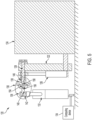
- Figure 3 illustrates a side view of an example of the system 120, according to an example implementation.
- the first actuator 126 and the second actuator 132 are operated in a linear motion to cause rotation of the control lever 122, as shown, for a rotary input to the device 124.
- Figure 4 illustrates a front view of an example of the system 120, according to an example implementation. Figure 4 illustrates further details of the resettable frangible link 130 and the rod 128.
- the resettable frangible link 130 includes a magnetically or a mechanically frangible control rod link.
- the resettable frangible link 130 includes a magnetic coupling having a first half 136 and a second half 138 to couple the second actuator 132 to the control lever 122 via the rod 128.
- the first half 136 includes a base 140 for mating with a fitting 142 of the second actuator 132.
- the base 140 can include a ball-type quick attach fitting and the fitting 142 can include a socket into which the ball-type quick attach fitting is inserted.
- the first half 136 also includes a magnet 144 positioned in the base 140.
- the second half 138 includes a brace 146 attached to the rod 128, and a magnetic pole piece 148 positioned in the brace 146.
- the magnet 144 is magnetically connected to the magnetic pole piece 148.
- the brace 146 includes a threaded portion for attaching to corresponding threads on the rod 128, and the magnetic pole piece 148 is connected to the brace 146 using a screw attachment, for example.
- the resettable frangible link 130 will break under an induced bending load. For example, a magnetic force between the magnet 144 and the magnetic pole piece 148 will be overcome by the induced bending load.
- the second actuator 132 is then disconnected from the control lever 122 and the device 124 is operated using the first actuator 126.
- the base 140 is shown as oval to enable a breakaway at different forces (or force amounts) depending on any angle.
- the breakaway force may be lower at higher angles (e.g., as the fitting 142 tilts relative to the base 140).
- the control lever 122 moves through an arc having a wide angle of rotation (e.g., 90 degrees or more), and thus, the resettable frangible link 130 allows for breakaway of the second actuator 132 at any orientation and at the same amount of applied force.
- the resettable frangible link 130 is not required to be in line with the rod 128 (axially, or in plane). This allows for many options for mounting hardware, and can be accomplished by the base 140 being the ball and socket type configuration, where the base 140 is round and the fitting 142 mating surface is a matching round hole. Using the magnet 144 for the connection allows for easy disconnect and quick resetting of the resettable frangible link 130. The magnet 144 and the base 140 profile also allows for a precise control of a break point load. The shape of the base 140 can be altered from circular to adjust the break point load too.
- the system 120 is resettable and is configured to break within a prescribed applied force.
- the breakaway force is predictable and consistent.
- the breakaway force is also abrupt such that there is no intermediate break position that is achieved.
- either the first actuator 126 or the second actuator 132 is in control of the control lever 122.
- both the first actuator 126 and the second actuator 132 are in control of the control lever 122.
- the second actuator 132 is disconnected abruptly.
- the magnet 144 enables the resettable frangible link 130 to break consistently with the same torque, and can be easily reset by realigning the magnet 144 with the magnetic pole piece 148.
- the magnet 144 is a permanent magnet.
- the magnet is an electro-magnet
- the system 120 further includes a control system 150 coupled to the electro-magnet for controlling a magnetic attraction force of the electro-magnet.
- the control system 150 is shown coupled to a base of the first actuator 126 and wiring coupling to the magnet 144 and/or the magnetic pole piece 148 is internal to the first actuator 126.
- the first actuator 126 is always connected to the rod 128, and thus, an electrical connection between the magnet 144 and the control system 150 is always in place.
- the control system 150 includes a processor, memory, and instructions stored on the memory executable by the processor to perform functions.
- the control system 150 can be programmed to alter the magnetic attraction force of the electro-magnet based on an operating condition of the device 124.
- the control system 150 can alter the magnetic force to vary a separation or break-away force that is required.
- the control system 150 in this scenario alters the magnetic force to be stronger to prevent an undesired break-away caused by turbulence.
- a stage of flight can be used as a basis for the control system 150 to alter the magnetic force of the magnet 144 by increasing, decreasing, or otherwise changing an amount of power provided to the electro-magnet.
- control system 150 alters the magnetic force of the electro-magnet based on weather conditions in which the device 124 operates.
- the control system 150 can be programmed to alter the magnetic force of the electro-magnet based on any combination of factors described herein too.
- control system 150 alters the magnetic force of the electro-magnet to tailor a positional angled break away force required.
- a sensor 152 is included for detecting an angle of the resettable frangible link 130 with respect to the second actuator 132, and the control system 150 alters the magnetic attraction force based on the angle.
- the control system 150 and electro-magnet can thus produce customized break away forces with respect to angle, as sensed by the positional sensor, which outputs signals to the control system 150 in a feedback loop to control force in position and time.
- Figure 5 illustrates a front view of another example of the system 120, according to an example implementation.
- the resettable frangible link 130 includes a mechanically frangible control rod 154 to couple the second actuator 132 to the control lever 122 via the rod 128.
- the first half 136 still includes the base 140 for mating with the fitting 142 of the second actuator 132, and the second half 138 includes the brace 146 attached to the rod 128.
- the mechanically frangible control rod 154 connects the first half 136 to the second half 138.
- the mechanically frangible control rod 154 has a first end 156 and a second end 158, and each of the first end 156 and the second end 158 is threaded such that the first end 156 attaches to the base 140 and the second end 158 attaches to the brace 146.
- the mechanically frangible control rod 154 is a tensile element.
- the mechanically frangible control rod 154 has a predefined preload and will break under a certain applied pressure.
- the broken fragments of the mechanically frangible control rod are unscrewed from both sides (e.g., from the base 140 and from the brace 146), and a new tensile element is inserted.
- Figure 6 shows a flowchart of an example of a method 200 for overriding autonomous control of the device 124, according to an example implementation.
- Method 200 shown in Figure 6 presents an example of a method that could be used with the aircraft 100 shown in Figure 1 , with the system 120 shown in Figures 2-5 , or with the computing device 134 shown in Figure 7 , for example.
- devices or systems are used or configured to perform logical functions presented in Figure 6 .
- components of the devices and/or systems are configured to perform the functions such that the components are actually configured and structured (with hardware and/or software) to enable such performance.
- components of the devices and/or systems are arranged to be adapted to, capable of, or suited for performing the functions, such as when operated in a specific manner.
- Method 200 includes one or more operations, functions, or actions as illustrated by one or more of blocks 202-206. Although the blocks are illustrated in a sequential order, these blocks may also be performed in parallel, and/or in a different order than those described herein.
- each block or portions of each block may represent a module, a segment, or a portion of program code, which includes one or more instructions executable by a processor for implementing specific logical functions or steps in the process.
- the program code is be stored on any type of computer readable medium or data storage, for example, such as a storage device including a disk or hard drive. Further, the program code can be encoded on a computer-readable storage media in a machine-readable format, or on other non-transitory media or articles of manufacture.
- the computer readable medium may include non-transitory computer readable medium or memory, for example, such as computer-readable media that stores data for short periods of time like register memory, processor cache and Random Access Memory (RAM).
- the computer readable medium may also include non-transitory media, such as secondary or persistent long term storage, like read only memory (ROM), optical or magnetic disks, compact-disc read only memory (CD-ROM), for example.
- the computer readable media may also be any other volatile or non-volatile storage systems.
- the computer readable medium may be considered a tangible computer readable storage medium, for example.
- each block or portions of each block in Figure 6 may represent circuitry that is wired to perform the specific logical functions in the process.
- Alternative implementations are included within the scope of the examples of the present disclosure in which functions may be executed out of order from that shown or discussed, including substantially concurrent or in reverse order, depending on the functionality involved, as would be understood by those reasonably skilled in the art.
- the method 200 includes controlling the control lever 122 of the device 124 via the first actuator 126 during manual operation mode of the device 124, and the first actuator 126 is coupled to the control lever 122 via the rod 128.
- the method 200 includes controlling the control lever 122 of the device 124 via the second actuator 132 during autonomous operation mode of the device 124, and the resettable frangible link 130 couples the second actuator 132 to the control lever 122 via the rod 128.
- the resettable frangible link 130 includes a magnetic coupling having the first half 136 and the second half 138 to couple the second actuator 132 to the control lever 122 via the rod 128, and the method 200 further includes realigning the first half 136 and the second half 138 of the magnetic coupling causing a magnetic attachment of the first half 136 and the second half 138 in order to reattach the second actuator 132 to the rod 128 for reentering the autonomous operation mode of the device 124.
- the realignment is performed by a manual attachment.
- the realignment occurs by magnetic reattachment of the magnet 144 to the magnetic pole piece 148.
- the system 120 is shown to include a computing device 134.
- the control system 150 takes the form of a computing device too.
- Figure 7 illustrates an example of the computing device 134, according to an example implementation.
- the computing device 134 includes one or more processors 160, instructions 162 stored on non-transitory computer readable media 164, a communication interface 166, an output interface 168, and each component of the computing device 134 is connected to a communication bus 170.
- the computing device 134 also includes hardware to enable communication within the computing device 134 and between the computing device 134 and other devices (not shown).
- the hardware may include transmitters, receivers, and antennas, for example.
- the communication interface 166 is a wireless interface and/or one or more wireline interfaces that allow for both short-range communication and long-range communication to one or more networks or to one or more remote devices.
- Such wireless interfaces provide for communication under one or more wireless communication protocols, Bluetooth, WiFi (e.g., an institute of electrical and electronic engineers (IEEE) 802.11 protocol), Long-Term Evolution (LTE), cellular communications, near-field communication (NFC), and/or other wireless communication protocols.
- wireline interfaces include an Ethernet interface, a Universal Serial Bus (USB) interface, or similar interface to communicate via a wire, a twisted pair of wires, a coaxial cable, an optical link, a fiber-optic link, or other physical connection to a wireline network.
- the communication interface 166 is configured to receive input data from one or more devices, and is also configured to send output data to other devices.
- the non-transitory computer readable media 164 includes or take the form of memory, such as one or more computer-readable storage media that can be read or accessed by the one or more processors 160.
- the computer-readable storage media can include volatile and/or non-volatile storage components, such as optical, magnetic, organic or other memory or disc storage, which can be integrated in whole or in part with the one or more processors 160.
- the non-transitory computer readable media 164 is considered non-transitory computer readable media.
- the non-transitory computer readable media 164 can be implemented using a single physical device (e.g., one optical, magnetic, organic or other memory or disc storage unit), while in other examples, the non-transitory computer readable media 164 can be implemented using two or more physical devices.
- the non-transitory computer readable media 164 thus is a computer readable medium, and the instructions 162 are stored thereon.
- the instructions 162 include computer executable code.
- the one or more processors 160 are general-purpose processors or special purpose processors (e.g., digital signal processors, application specific integrated circuits, etc.).
- the one or more processors 160 receive inputs from the communication interface 166 as well as outputs from other sensors (e.g., the sensor 152), and process them to generate outputs that are stored in the non-transitory computer readable media 164.
- the one or more processors 160 can be configured to execute the instructions 162 (e.g., computer-readable program instructions) that are stored in the non-transitory computer readable media 164 and are executable to provide the functionality of the computing device 134 described herein.
- the output interface 168 outputs information for reporting or storage, and thus, the output interface 168 is similar to the communication interface 166 and can be a wireless interface (e.g., transmitter) or a wired interface as well.
Landscapes
- Engineering & Computer Science (AREA)
- Aviation & Aerospace Engineering (AREA)
- Automation & Control Theory (AREA)
- Physics & Mathematics (AREA)
- General Physics & Mathematics (AREA)
- Mechanical Engineering (AREA)
- Mechanical Control Devices (AREA)
Claims (15)
- System (120), das aufweist:einen Steuerhebel (122) zum Steuern eines Betriebs einer Vorrichtung (124);einen ersten Aktuator (126), der über eine Stange (128) an den Steuerhebel (122) gekoppelt ist; undein rücksetzbares zerbrechliches Glied (130), das einen zweiten Aktuator (132) an den Steuerhebel (122) über die Stange (128) koppelt, wobei das rücksetzbare zerbrechliche Glied (130) eine Trennung einer Kopplung des zweiten Aktuators (132) von dem Steuerhebel (122) basierend auf einer Kraft ermöglicht, die durch den ersten Aktuator (126) auf die Stange (128) ausgeübt wird.
- System nach Anspruch 1, wobei der Steuerhebel (122) einen Betrieb der Vorrichtung (124) unter Verwendung einer Umlenkhebelbewegung steuert.
- System nach Anspruch 1 oder 2, wobei der Steuerhebel (122) ein Schubhebel ist, und wobei das System ferner einen Motor (110a-b) aufweist, der an den Schubhebel gekoppelt ist, wobei ein Betrieb des ersten Aktuators (126) oder des zweiten Aktuators (132) einen Betrieb des Motors steuert.
- System nach einem der Ansprüche 1-3, wobei während eines autonomen Betriebsmodus der Vorrichtung (124) der zweite Aktuator (132) zum Steuern des Steuerhebels (122) verwendet wird, und wobei während eines manuellen Betriebsmodus der Vorrichtung (124) der erste Aktuator (126) durch eine Bedienperson zum Steuern des Steuerhebels (122) verwendet wird, und wobei der manuelle Betriebsmodus durch die Stange (128) eingegeben wird, die die Kraft aufnimmt, die durch den ersten Aktuator (126) ausgeübt wird, was das rücksetzbare zerbrechliche Glied (130) den zweiten Aktuator (132) von der Stange (128) trennen lässt.
- System nach einem der Ansprüche 1-4, wobei das rücksetzbare zerbrechliche Glied (130) eine Trennung einer Kopplung des zweiten Aktuators (132) von dem Steuerhebel (122) in jeder Rotationsausrichtung des Steuerhebels (122) in Bezug auf eine Vorrichtung (124) ermöglicht.
- System nach einem der Ansprüche 1-5, wobei der Steuerhebel (122) ein Schubhebel für ein Luftfahrzeug (100) ist, wobei der erste Aktuator (126) eine Steuerstange (128) für einen Piloten zur Verwendung für eine Steuerung des Schubhebels ist, und wobei der zweite Aktuator (132) eine weitere Steuerstange (128) ist, die durch eine Berechnungsvorrichtung (134) für einen autonomen Betrieb gesteuert wird.
- System nach einem der Ansprüche 1-6, wobei der erste Aktuator (126) permanent an dem Steuerhebel (122) über die Stange (128) angebracht ist.
- System nach einem der Ansprüche 1-7, wobei der erste Aktuator (126) und der zweite Aktuator (132) jeweils dazu fähig sind, den Steuerhebel (122) unabhängig zu steuern, wobei basierend auf der Kraft, die durch den ersten Aktuator (126) auf die Stange (128) ausgeübt wird, der erste Aktuator (126) den zweiten Aktuator (132) übersteuert.
- System nach einem der Ansprüche 1-8, wobei das rücksetzbare zerbrechliche Glied (130) eine mechanisch zerbrechliche Steuerstange (154) umfasst, um den zweiten Aktuator (132) an den Steuerhebel (122) über die Stange (128) zu koppeln.
- System nach einem der Ansprüche 1-9; wobei das rücksetzbare zerbrechliche Glied (130) aufweist:eine Basis (142), die zu einem Anschlussstück des zweiten Aktuators (132) passt;eine Strebe (146), die an der Stange (128) angebracht ist; undeine mechanisch zerbrechliche Steuerstange (154) mit einem ersten Ende (156) und mit einem zweiten Ende (158), und wobei sowohl das erste Ende als auch das zweite Ende mit einem Gewinde versehen sind, so dass das erste Ende an der Basis (142) angebracht ist und das zweite Ende an der Strebe (146) angebracht ist.
- System nach einem der Ansprüche 1-10, wobei das rücksetzbare zerbrechliche Glied (130) aufweist:eine Basis (142), die zu einem Anschlussstück des zweiten Aktuators (132) passt;einen Magnet (144), der in der Basis (142) positioniert ist;eine Strebe (146), die an der Stange (128) angebracht ist; undein magnetischer Pol (148), der in der Strebe (146) positioniert ist; wobei der Magnet (144) magnetisch mit dem magnetischen Pol (148) verbunden ist.
- System nach Anspruch 11, wobei der Magnet (144) ein Elektromagnet (144) ist, und wobei das System ferner aufweist:
ein Steuersystem (150), das an den Elektromagnet zum Steuern einer magnetischen Anziehungskraft des Elektromagneten (144) gekoppelt ist. - Luftfahrzeug (100), das aufweist:einen Motor (11 0a-b);ein System (120) gemäß einem der Ansprüche 1-12, das an den Motor gekoppelt ist, wobei der Steuerhebel (122) einen Betrieb des Motors steuert,wobei während eines autonomen Betriebsmodus des Motors der zweite Aktuator (132) zum Steuern des Steuerhebels (122) des Motors verwendet wird,wobei während eines manuellen Betriebsmodus des Motors der erste Aktuator (126) durch eine Bedienperson verwendet wird, um den Steuerhebel (122) des Motors zu steuern, undwobei der manuelle Betriebsmodus durch die Stange (128) eingegeben wird, die die Kraft aufnimmt, die durch den ersten Aktuator (126) ausgeübt wird, was das rücksetzbare zerbrechliche Glied (130) den zweiten Aktuator (132) von der Stange (128) trennen lässt.
- Verfahren (200) zum Übersteuern einer autonomen Steuerung einer Vorrichtung (124), wobei das Verfahren aufweist:Steuern (202) eines Steuerhebels (122) einer Vorrichtung (124) über einen ersten Aktuator (126) während eines manuellen Betriebsmodus der Vorrichtung (124), wobei der erste Aktuator (126) an den Steuerhebel (122) über eine Stange (128) gekoppelt ist;Steuern (204) des Steuerhebels (122) der Vorrichtung (124) über einen zweiten Aktuator (132) während eines autonomen Betriebsmodus der Vorrichtung (124), wobei ein rücksetzbares zerbrechliches Glied (130) den zweiten Aktuator (132) an den Steuerhebel (122) über eine Stange (128) koppelt; undEingeben (206) des manuellen Betriebsmodus durch die Stange (128), die eine ausgeübte Kraft über den ersten Aktuator (126) aufnimmt, was das rücksetzbare zerbrechliche Glied (130) den zweiten Aktuator (132) von der Stange (128) trennen lässt.
- Verfahren nach Anspruch 14, wobei das rücksetzbare zerbrechliche Glied (130) eine magnetische Kopplung mit einer ersten Hälfte (136) und mit einer zweiten Hälfte (138) umfasst, um den zweiten Aktuator (132) an den Steuerhebel (122) über die Stange (128) zu koppeln, und wobei das Verfahren ferner aufweist:
erneutes Ausrichten der ersten Hälfte (136) und der zweiten Hälfte (138) der magnetischen Kopplung, was eine magnetische Anbringung der ersten Hälfte und der zweiten Hälfte verursacht, um den zweiten Aktuator (132) erneut an der Stange (128) zum erneuten Eingeben des autonomen Betriebsmodus der Vorrichtung (124) anzubringen.
Applications Claiming Priority (1)
| Application Number | Priority Date | Filing Date | Title |
|---|---|---|---|
| US202063126774P | 2020-12-17 | 2020-12-17 |
Publications (2)
| Publication Number | Publication Date |
|---|---|
| EP4015366A1 EP4015366A1 (de) | 2022-06-22 |
| EP4015366B1 true EP4015366B1 (de) | 2024-07-24 |
Family
ID=78789661
Family Applications (1)
| Application Number | Title | Priority Date | Filing Date |
|---|---|---|---|
| EP21210107.5A Active EP4015366B1 (de) | 2020-12-17 | 2021-11-24 | Systeme und verfahren zum ausschalten der autonomen steuerung einer vorrichtung |
Country Status (3)
| Country | Link |
|---|---|
| US (3) | US12049301B2 (de) |
| EP (1) | EP4015366B1 (de) |
| CN (1) | CN114644109B (de) |
Family Cites Families (16)
| Publication number | Priority date | Publication date | Assignee | Title |
|---|---|---|---|---|
| US3199811A (en) * | 1963-02-28 | 1965-08-10 | Trans World Airlines Inc | Automatic aircraft throttle control apparatus |
| FR2680386B1 (fr) * | 1991-08-12 | 1993-11-05 | Aerospatiale Ste Nationale Indle | Dispositif pour la commande du regime des moteurs d'un aeronef. |
| US7044024B1 (en) | 2003-05-12 | 2006-05-16 | Trutrak Flight Systems, Inc. | Apparatus and method for servo control of an aircraft |
| US7624943B2 (en) * | 2006-03-22 | 2009-12-01 | The Boeing Company | Multi-mode unmanned and manned vehicle systems and methods |
| US9150308B2 (en) * | 2012-02-10 | 2015-10-06 | Merlin Technology, Inc. | Rotorcraft autopilot system, components and methods |
| FR3005934B1 (fr) | 2013-05-23 | 2015-05-01 | Airbus Operations Sas | Systeme et procede de commande d’un aeronef |
| US9284996B2 (en) * | 2013-10-23 | 2016-03-15 | Sikorsky Aircraft Corporation | Selective electrical control of electromechanical clutch assembly |
| US9366296B2 (en) | 2014-01-13 | 2016-06-14 | The Boeing Company | Swaging features that lock retaining elements for bearings |
| US9828108B2 (en) * | 2016-03-10 | 2017-11-28 | The Boeing Company | Automated flight throttle control |
| US10458443B2 (en) | 2016-04-04 | 2019-10-29 | The Boeing Company | Actuator having an internal conductive path |
| EP3257745B1 (de) * | 2016-06-15 | 2019-05-29 | Ratier-Figeac SAS | Umschaltung zwischen autopilot und manueller kontrolle |
| US10329008B2 (en) | 2016-06-24 | 2019-06-25 | The Boeing Company | Fluid-tight mechanical fastening system and associated structural assembly |
| US10265760B2 (en) | 2016-08-12 | 2019-04-23 | The Boeing Company | Sliding adjustable toggle clamp |
| US10137999B2 (en) | 2017-03-30 | 2018-11-27 | The Boeing Company | Methods and apparatus for detecting airflow control surface skew conditions |
| US10793257B2 (en) * | 2018-02-05 | 2020-10-06 | The Boeing Company | Flight control systems and methods for an aerial vehicle |
| US11203415B2 (en) | 2018-12-06 | 2021-12-21 | The Boeing Company | Flight control cable sensor for an aircraft |
-
2021
- 2021-11-23 US US17/533,237 patent/US12049301B2/en active Active
- 2021-11-24 EP EP21210107.5A patent/EP4015366B1/de active Active
- 2021-12-16 CN CN202111541405.2A patent/CN114644109B/zh active Active
-
2024
- 2024-06-28 US US18/757,746 patent/US12325509B2/en active Active
-
2025
- 2025-05-16 US US19/210,076 patent/US20250276786A1/en active Pending
Also Published As
| Publication number | Publication date |
|---|---|
| US20220194561A1 (en) | 2022-06-23 |
| US12325509B2 (en) | 2025-06-10 |
| US12049301B2 (en) | 2024-07-30 |
| CN114644109A (zh) | 2022-06-21 |
| CN114644109B (zh) | 2026-02-24 |
| EP4015366A1 (de) | 2022-06-22 |
| US20250276786A1 (en) | 2025-09-04 |
| US20240351681A1 (en) | 2024-10-24 |
Similar Documents
| Publication | Publication Date | Title |
|---|---|---|
| US8944372B2 (en) | Device for detecting breakage of a primary path in a flight control actuator | |
| EP3459798B1 (de) | Primäres bremsregelsystem mit abwechselnder fahrzeugsystemüberbrückung | |
| US9284996B2 (en) | Selective electrical control of electromechanical clutch assembly | |
| WO1994003854A9 (en) | Failsafe digital bus to analog protocol converter system | |
| US10703498B2 (en) | Methods and aircraft for optimized reverse thrust operation during landing | |
| US20220063794A1 (en) | Force application device for a control stick of an aircraft | |
| EP3661825B1 (de) | Steuergerät zur roboterlenkung zur optimalen bewertung freier antworten | |
| US7837143B2 (en) | Method and apparatus for disabling pilot control of a hijacked aircraft | |
| CN113443125B (zh) | 一种用于飞行器的高升力系统及其控制方法 | |
| EP4015366B1 (de) | Systeme und verfahren zum ausschalten der autonomen steuerung einer vorrichtung | |
| EP3680635A1 (de) | System zur detektion der trennung einer rfid-steueroberfläche | |
| WO2015122876A1 (en) | Magnetic positive detent for helicopter pilot input | |
| CN108216582B (zh) | 一种飞机失速保护控制系统 | |
| KR101494780B1 (ko) | 무인항공기의 전기식 구동장치와 그것의 제어방법 | |
| CN119356069A (zh) | 基于时间敏感网络的eVTOL飞控系统及控制方法 | |
| CN215922312U (zh) | 一种线控转向系统和自动驾驶载具 | |
| US11662001B2 (en) | Dual drive redundant load transmission device and process | |
| EP3578465B1 (de) | System zur detektion der trennung von steuerflächen mit rfid | |
| US20240308648A1 (en) | Fly-by-wire flight control system with back-up control in an inceptor | |
| CN112306074B (zh) | 一种用于自动驾驶仪的超控断开装置和超控断开方法 | |
| KR101885663B1 (ko) | 기계식 조종장치를 백업으로 갖는 전자식 비행제어 시스템 | |
| CN119749576A (zh) | 一种域控制器及车辆控制系统 |
Legal Events
| Date | Code | Title | Description |
|---|---|---|---|
| PUAI | Public reference made under article 153(3) epc to a published international application that has entered the european phase |
Free format text: ORIGINAL CODE: 0009012 |
|
| STAA | Information on the status of an ep patent application or granted ep patent |
Free format text: STATUS: THE APPLICATION HAS BEEN PUBLISHED |
|
| AK | Designated contracting states |
Kind code of ref document: A1 Designated state(s): AL AT BE BG CH CY CZ DE DK EE ES FI FR GB GR HR HU IE IS IT LI LT LU LV MC MK MT NL NO PL PT RO RS SE SI SK SM TR |
|
| STAA | Information on the status of an ep patent application or granted ep patent |
Free format text: STATUS: REQUEST FOR EXAMINATION WAS MADE |
|
| 17P | Request for examination filed |
Effective date: 20221202 |
|
| RBV | Designated contracting states (corrected) |
Designated state(s): AL AT BE BG CH CY CZ DE DK EE ES FI FR GB GR HR HU IE IS IT LI LT LU LV MC MK MT NL NO PL PT RO RS SE SI SK SM TR |
|
| RAP3 | Party data changed (applicant data changed or rights of an application transferred) |
Owner name: THE BOEING COMPANY |
|
| GRAP | Despatch of communication of intention to grant a patent |
Free format text: ORIGINAL CODE: EPIDOSNIGR1 |
|
| STAA | Information on the status of an ep patent application or granted ep patent |
Free format text: STATUS: GRANT OF PATENT IS INTENDED |
|
| INTG | Intention to grant announced |
Effective date: 20231113 |
|
| GRAJ | Information related to disapproval of communication of intention to grant by the applicant or resumption of examination proceedings by the epo deleted |
Free format text: ORIGINAL CODE: EPIDOSDIGR1 |
|
| STAA | Information on the status of an ep patent application or granted ep patent |
Free format text: STATUS: REQUEST FOR EXAMINATION WAS MADE |
|
| GRAP | Despatch of communication of intention to grant a patent |
Free format text: ORIGINAL CODE: EPIDOSNIGR1 |
|
| STAA | Information on the status of an ep patent application or granted ep patent |
Free format text: STATUS: GRANT OF PATENT IS INTENDED |
|
| INTC | Intention to grant announced (deleted) | ||
| INTG | Intention to grant announced |
Effective date: 20240223 |
|
| GRAS | Grant fee paid |
Free format text: ORIGINAL CODE: EPIDOSNIGR3 |
|
| GRAA | (expected) grant |
Free format text: ORIGINAL CODE: 0009210 |
|
| STAA | Information on the status of an ep patent application or granted ep patent |
Free format text: STATUS: THE PATENT HAS BEEN GRANTED |
|
| AK | Designated contracting states |
Kind code of ref document: B1 Designated state(s): AL AT BE BG CH CY CZ DE DK EE ES FI FR GB GR HR HU IE IS IT LI LT LU LV MC MK MT NL NO PL PT RO RS SE SI SK SM TR |
|
| REG | Reference to a national code |
Ref country code: GB Ref legal event code: FG4D |
|
| REG | Reference to a national code |
Ref country code: CH Ref legal event code: EP |
|
| P01 | Opt-out of the competence of the unified patent court (upc) registered |
Free format text: CASE NUMBER: APP_38845/2024 Effective date: 20240628 |
|
| REG | Reference to a national code |
Ref country code: IE Ref legal event code: FG4D Ref country code: DE Ref legal event code: R096 Ref document number: 602021016077 Country of ref document: DE |
|
| REG | Reference to a national code |
Ref country code: LT Ref legal event code: MG9D |
|
| REG | Reference to a national code |
Ref country code: NL Ref legal event code: MP Effective date: 20240724 |
|
| PG25 | Lapsed in a contracting state [announced via postgrant information from national office to epo] |
Ref country code: PT Free format text: LAPSE BECAUSE OF FAILURE TO SUBMIT A TRANSLATION OF THE DESCRIPTION OR TO PAY THE FEE WITHIN THE PRESCRIBED TIME-LIMIT Effective date: 20241125 |
|
| REG | Reference to a national code |
Ref country code: AT Ref legal event code: MK05 Ref document number: 1706086 Country of ref document: AT Kind code of ref document: T Effective date: 20240724 |
|
| PG25 | Lapsed in a contracting state [announced via postgrant information from national office to epo] |
Ref country code: NL Free format text: LAPSE BECAUSE OF FAILURE TO SUBMIT A TRANSLATION OF THE DESCRIPTION OR TO PAY THE FEE WITHIN THE PRESCRIBED TIME-LIMIT Effective date: 20240724 |
|
| PG25 | Lapsed in a contracting state [announced via postgrant information from national office to epo] |
Ref country code: PT Free format text: LAPSE BECAUSE OF FAILURE TO SUBMIT A TRANSLATION OF THE DESCRIPTION OR TO PAY THE FEE WITHIN THE PRESCRIBED TIME-LIMIT Effective date: 20241125 Ref country code: NL Free format text: LAPSE BECAUSE OF FAILURE TO SUBMIT A TRANSLATION OF THE DESCRIPTION OR TO PAY THE FEE WITHIN THE PRESCRIBED TIME-LIMIT Effective date: 20240724 |
|
| PG25 | Lapsed in a contracting state [announced via postgrant information from national office to epo] |
Ref country code: NO Free format text: LAPSE BECAUSE OF FAILURE TO SUBMIT A TRANSLATION OF THE DESCRIPTION OR TO PAY THE FEE WITHIN THE PRESCRIBED TIME-LIMIT Effective date: 20241024 |
|
| PG25 | Lapsed in a contracting state [announced via postgrant information from national office to epo] |
Ref country code: FI Free format text: LAPSE BECAUSE OF FAILURE TO SUBMIT A TRANSLATION OF THE DESCRIPTION OR TO PAY THE FEE WITHIN THE PRESCRIBED TIME-LIMIT Effective date: 20240724 Ref country code: PL Free format text: LAPSE BECAUSE OF FAILURE TO SUBMIT A TRANSLATION OF THE DESCRIPTION OR TO PAY THE FEE WITHIN THE PRESCRIBED TIME-LIMIT Effective date: 20240724 Ref country code: GR Free format text: LAPSE BECAUSE OF FAILURE TO SUBMIT A TRANSLATION OF THE DESCRIPTION OR TO PAY THE FEE WITHIN THE PRESCRIBED TIME-LIMIT Effective date: 20241025 |
|
| PG25 | Lapsed in a contracting state [announced via postgrant information from national office to epo] |
Ref country code: BG Free format text: LAPSE BECAUSE OF FAILURE TO SUBMIT A TRANSLATION OF THE DESCRIPTION OR TO PAY THE FEE WITHIN THE PRESCRIBED TIME-LIMIT Effective date: 20240724 |
|
| PG25 | Lapsed in a contracting state [announced via postgrant information from national office to epo] |
Ref country code: LV Free format text: LAPSE BECAUSE OF FAILURE TO SUBMIT A TRANSLATION OF THE DESCRIPTION OR TO PAY THE FEE WITHIN THE PRESCRIBED TIME-LIMIT Effective date: 20240724 |
|
| PG25 | Lapsed in a contracting state [announced via postgrant information from national office to epo] |
Ref country code: AT Free format text: LAPSE BECAUSE OF FAILURE TO SUBMIT A TRANSLATION OF THE DESCRIPTION OR TO PAY THE FEE WITHIN THE PRESCRIBED TIME-LIMIT Effective date: 20240724 Ref country code: IS Free format text: LAPSE BECAUSE OF FAILURE TO SUBMIT A TRANSLATION OF THE DESCRIPTION OR TO PAY THE FEE WITHIN THE PRESCRIBED TIME-LIMIT Effective date: 20241124 |
|
| PG25 | Lapsed in a contracting state [announced via postgrant information from national office to epo] |
Ref country code: HR Free format text: LAPSE BECAUSE OF FAILURE TO SUBMIT A TRANSLATION OF THE DESCRIPTION OR TO PAY THE FEE WITHIN THE PRESCRIBED TIME-LIMIT Effective date: 20240724 |
|
| PG25 | Lapsed in a contracting state [announced via postgrant information from national office to epo] |
Ref country code: RS Free format text: LAPSE BECAUSE OF FAILURE TO SUBMIT A TRANSLATION OF THE DESCRIPTION OR TO PAY THE FEE WITHIN THE PRESCRIBED TIME-LIMIT Effective date: 20241024 Ref country code: ES Free format text: LAPSE BECAUSE OF FAILURE TO SUBMIT A TRANSLATION OF THE DESCRIPTION OR TO PAY THE FEE WITHIN THE PRESCRIBED TIME-LIMIT Effective date: 20240724 |
|
| PG25 | Lapsed in a contracting state [announced via postgrant information from national office to epo] |
Ref country code: RS Free format text: LAPSE BECAUSE OF FAILURE TO SUBMIT A TRANSLATION OF THE DESCRIPTION OR TO PAY THE FEE WITHIN THE PRESCRIBED TIME-LIMIT Effective date: 20241024 Ref country code: PL Free format text: LAPSE BECAUSE OF FAILURE TO SUBMIT A TRANSLATION OF THE DESCRIPTION OR TO PAY THE FEE WITHIN THE PRESCRIBED TIME-LIMIT Effective date: 20240724 Ref country code: NO Free format text: LAPSE BECAUSE OF FAILURE TO SUBMIT A TRANSLATION OF THE DESCRIPTION OR TO PAY THE FEE WITHIN THE PRESCRIBED TIME-LIMIT Effective date: 20241024 Ref country code: LV Free format text: LAPSE BECAUSE OF FAILURE TO SUBMIT A TRANSLATION OF THE DESCRIPTION OR TO PAY THE FEE WITHIN THE PRESCRIBED TIME-LIMIT Effective date: 20240724 Ref country code: IS Free format text: LAPSE BECAUSE OF FAILURE TO SUBMIT A TRANSLATION OF THE DESCRIPTION OR TO PAY THE FEE WITHIN THE PRESCRIBED TIME-LIMIT Effective date: 20241124 Ref country code: HR Free format text: LAPSE BECAUSE OF FAILURE TO SUBMIT A TRANSLATION OF THE DESCRIPTION OR TO PAY THE FEE WITHIN THE PRESCRIBED TIME-LIMIT Effective date: 20240724 Ref country code: GR Free format text: LAPSE BECAUSE OF FAILURE TO SUBMIT A TRANSLATION OF THE DESCRIPTION OR TO PAY THE FEE WITHIN THE PRESCRIBED TIME-LIMIT Effective date: 20241025 Ref country code: FI Free format text: LAPSE BECAUSE OF FAILURE TO SUBMIT A TRANSLATION OF THE DESCRIPTION OR TO PAY THE FEE WITHIN THE PRESCRIBED TIME-LIMIT Effective date: 20240724 Ref country code: ES Free format text: LAPSE BECAUSE OF FAILURE TO SUBMIT A TRANSLATION OF THE DESCRIPTION OR TO PAY THE FEE WITHIN THE PRESCRIBED TIME-LIMIT Effective date: 20240724 Ref country code: BG Free format text: LAPSE BECAUSE OF FAILURE TO SUBMIT A TRANSLATION OF THE DESCRIPTION OR TO PAY THE FEE WITHIN THE PRESCRIBED TIME-LIMIT Effective date: 20240724 Ref country code: AT Free format text: LAPSE BECAUSE OF FAILURE TO SUBMIT A TRANSLATION OF THE DESCRIPTION OR TO PAY THE FEE WITHIN THE PRESCRIBED TIME-LIMIT Effective date: 20240724 |
|
| PG25 | Lapsed in a contracting state [announced via postgrant information from national office to epo] |
Ref country code: RO Free format text: LAPSE BECAUSE OF FAILURE TO SUBMIT A TRANSLATION OF THE DESCRIPTION OR TO PAY THE FEE WITHIN THE PRESCRIBED TIME-LIMIT Effective date: 20240724 Ref country code: SM Free format text: LAPSE BECAUSE OF FAILURE TO SUBMIT A TRANSLATION OF THE DESCRIPTION OR TO PAY THE FEE WITHIN THE PRESCRIBED TIME-LIMIT Effective date: 20240724 Ref country code: DK Free format text: LAPSE BECAUSE OF FAILURE TO SUBMIT A TRANSLATION OF THE DESCRIPTION OR TO PAY THE FEE WITHIN THE PRESCRIBED TIME-LIMIT Effective date: 20240724 |
|
| PG25 | Lapsed in a contracting state [announced via postgrant information from national office to epo] |
Ref country code: EE Free format text: LAPSE BECAUSE OF FAILURE TO SUBMIT A TRANSLATION OF THE DESCRIPTION OR TO PAY THE FEE WITHIN THE PRESCRIBED TIME-LIMIT Effective date: 20240724 |
|
| PG25 | Lapsed in a contracting state [announced via postgrant information from national office to epo] |
Ref country code: CZ Free format text: LAPSE BECAUSE OF FAILURE TO SUBMIT A TRANSLATION OF THE DESCRIPTION OR TO PAY THE FEE WITHIN THE PRESCRIBED TIME-LIMIT Effective date: 20240724 |
|
| REG | Reference to a national code |
Ref country code: DE Ref legal event code: R097 Ref document number: 602021016077 Country of ref document: DE |
|
| PG25 | Lapsed in a contracting state [announced via postgrant information from national office to epo] |
Ref country code: SK Free format text: LAPSE BECAUSE OF FAILURE TO SUBMIT A TRANSLATION OF THE DESCRIPTION OR TO PAY THE FEE WITHIN THE PRESCRIBED TIME-LIMIT Effective date: 20240724 Ref country code: IT Free format text: LAPSE BECAUSE OF FAILURE TO SUBMIT A TRANSLATION OF THE DESCRIPTION OR TO PAY THE FEE WITHIN THE PRESCRIBED TIME-LIMIT Effective date: 20240724 |
|
| PLBE | No opposition filed within time limit |
Free format text: ORIGINAL CODE: 0009261 |
|
| STAA | Information on the status of an ep patent application or granted ep patent |
Free format text: STATUS: NO OPPOSITION FILED WITHIN TIME LIMIT |
|
| REG | Reference to a national code |
Ref country code: CH Ref legal event code: PL |
|
| 26N | No opposition filed |
Effective date: 20250425 |
|
| PG25 | Lapsed in a contracting state [announced via postgrant information from national office to epo] |
Ref country code: MC Free format text: LAPSE BECAUSE OF FAILURE TO SUBMIT A TRANSLATION OF THE DESCRIPTION OR TO PAY THE FEE WITHIN THE PRESCRIBED TIME-LIMIT Effective date: 20240724 |
|
| PG25 | Lapsed in a contracting state [announced via postgrant information from national office to epo] |
Ref country code: LU Free format text: LAPSE BECAUSE OF NON-PAYMENT OF DUE FEES Effective date: 20241124 |
|
| REG | Reference to a national code |
Ref country code: CH Ref legal event code: PL |
|
| PG25 | Lapsed in a contracting state [announced via postgrant information from national office to epo] |
Ref country code: CH Free format text: LAPSE BECAUSE OF NON-PAYMENT OF DUE FEES Effective date: 20241130 |
|
| REG | Reference to a national code |
Ref country code: BE Ref legal event code: MM Effective date: 20241130 |
|
| PG25 | Lapsed in a contracting state [announced via postgrant information from national office to epo] |
Ref country code: SE Free format text: LAPSE BECAUSE OF FAILURE TO SUBMIT A TRANSLATION OF THE DESCRIPTION OR TO PAY THE FEE WITHIN THE PRESCRIBED TIME-LIMIT Effective date: 20240724 |
|
| PG25 | Lapsed in a contracting state [announced via postgrant information from national office to epo] |
Ref country code: BE Free format text: LAPSE BECAUSE OF NON-PAYMENT OF DUE FEES Effective date: 20241130 |
|
| PG25 | Lapsed in a contracting state [announced via postgrant information from national office to epo] |
Ref country code: IE Free format text: LAPSE BECAUSE OF NON-PAYMENT OF DUE FEES Effective date: 20241124 |
|
| PGFP | Annual fee paid to national office [announced via postgrant information from national office to epo] |
Ref country code: DE Payment date: 20251128 Year of fee payment: 5 |
|
| PGFP | Annual fee paid to national office [announced via postgrant information from national office to epo] |
Ref country code: GB Payment date: 20251127 Year of fee payment: 5 |
|
| PGFP | Annual fee paid to national office [announced via postgrant information from national office to epo] |
Ref country code: FR Payment date: 20251125 Year of fee payment: 5 |
|
| PG25 | Lapsed in a contracting state [announced via postgrant information from national office to epo] |
Ref country code: HU Free format text: LAPSE BECAUSE OF FAILURE TO SUBMIT A TRANSLATION OF THE DESCRIPTION OR TO PAY THE FEE WITHIN THE PRESCRIBED TIME-LIMIT; INVALID AB INITIO Effective date: 20211124 |
|
| PG25 | Lapsed in a contracting state [announced via postgrant information from national office to epo] |
Ref country code: CY Free format text: LAPSE BECAUSE OF FAILURE TO SUBMIT A TRANSLATION OF THE DESCRIPTION OR TO PAY THE FEE WITHIN THE PRESCRIBED TIME-LIMIT; INVALID AB INITIO Effective date: 20211124 |