EP4015328A1 - Motor vehicle and method for operating a motor vehicle - Google Patents
Motor vehicle and method for operating a motor vehicle Download PDFInfo
- Publication number
- EP4015328A1 EP4015328A1 EP21211698.2A EP21211698A EP4015328A1 EP 4015328 A1 EP4015328 A1 EP 4015328A1 EP 21211698 A EP21211698 A EP 21211698A EP 4015328 A1 EP4015328 A1 EP 4015328A1
- Authority
- EP
- European Patent Office
- Prior art keywords
- motor vehicle
- compensating
- determined
- geometry
- compensating element
- Prior art date
- Legal status (The legal status is an assumption and is not a legal conclusion. Google has not performed a legal analysis and makes no representation as to the accuracy of the status listed.)
- Pending
Links
Images

Classifications
-
- B—PERFORMING OPERATIONS; TRANSPORTING
- B62—LAND VEHICLES FOR TRAVELLING OTHERWISE THAN ON RAILS
- B62D—MOTOR VEHICLES; TRAILERS
- B62D15/00—Steering not otherwise provided for
- B62D15/02—Steering position indicators ; Steering position determination; Steering aids
- B62D15/027—Parking aids, e.g. instruction means
- B62D15/0285—Parking performed automatically
-
- B—PERFORMING OPERATIONS; TRANSPORTING
- B60—VEHICLES IN GENERAL
- B60P—VEHICLES ADAPTED FOR LOAD TRANSPORTATION OR TO TRANSPORT, TO CARRY, OR TO COMPRISE SPECIAL LOADS OR OBJECTS
- B60P3/00—Vehicles adapted to transport, to carry or to comprise special loads or objects
- B60P3/32—Vehicles adapted to transport, to carry or to comprise special loads or objects comprising living accommodation for people, e.g. caravans, camping, or like vehicles
- B60P3/36—Auxiliary arrangements; Arrangements of living accommodation; Details
-
- B—PERFORMING OPERATIONS; TRANSPORTING
- B60—VEHICLES IN GENERAL
- B60T—VEHICLE BRAKE CONTROL SYSTEMS OR PARTS THEREOF; BRAKE CONTROL SYSTEMS OR PARTS THEREOF, IN GENERAL; ARRANGEMENT OF BRAKING ELEMENTS ON VEHICLES IN GENERAL; PORTABLE DEVICES FOR PREVENTING UNWANTED MOVEMENT OF VEHICLES; VEHICLE MODIFICATIONS TO FACILITATE COOLING OF BRAKES
- B60T3/00—Portable devices for preventing unwanted movement of vehicles, e.g. chocks
-
- B—PERFORMING OPERATIONS; TRANSPORTING
- B66—HOISTING; LIFTING; HAULING
- B66F—HOISTING, LIFTING, HAULING OR PUSHING, NOT OTHERWISE PROVIDED FOR, e.g. DEVICES WHICH APPLY A LIFTING OR PUSHING FORCE DIRECTLY TO THE SURFACE OF A LOAD
- B66F7/00—Lifting frames, e.g. for lifting vehicles; Platform lifts
- B66F7/24—Lifting frames, e.g. for lifting vehicles; Platform lifts for raising or lowering vehicles by their own power
- B66F7/243—Ramps
Definitions
- the invention relates to a method for operating a motor vehicle and a motor vehicle.
- a sloping position can be undesirable, especially in a mobile home. It is known in principle to compensate for an inclined position of a camper by means of at least one compensating wedge by placing the camper with a wheel on the compensating wedge. Here, however, it can be very difficult for the driver of the motorhome to place the respective wheel precisely on the associated compensating wedge due to poor visibility of the respective wheels of the mobile home from a driver's seat in the mobile home.
- U1 From the DE 20 2009 012 107 U1 is already a device for signaling the wheel position of a mobile home, sales vehicle or the like, wherein the device is mounted on a ramp.
- the device includes sensors which can report to a driver of the mobile home or the sales vehicle how far the wheel is on the ramp and when the end of the ramp has been reached.
- the invention relates to a method for operating a motor vehicle, in which a user input characterizing a length of a route is received by means of an electronic computing device and the motor vehicle is moved at least partially automatically by means of a control device along the length characterized by the user input.
- a person covers the distance for the motor vehicle via the user input and the motor vehicle is moved by means of the control device for the predetermined length of the route.
- the motor vehicle is designed as a mobile home, if the mobile home is to be arranged on at least one compensating wedge to compensate for an incline, the person can specify how far the mobile home should go up along the compensating wedge. The person can thus use the user input to trigger the particularly precise movement of the motor vehicle for the specified length.
- an oblique alignment of the motor vehicle relative to a horizontal plane is determined by means of an orientation detection device.
- a pivoting of the motor vehicle about a vehicle longitudinal axis and/or about a vehicle transverse axis relative to the horizontal plane is determined by means of the orientation detection device.
- the orientation of the horizontal plane can be predetermined so that it intersects a weight force vector of the motor vehicle perpendicularly.
- the orientation detection device is thus used to determine whether the motor vehicle is aligned at an angle to the horizontal plane and is therefore pivoted about the vehicle longitudinal axis and/or the vehicle transverse axis relative to the horizontal plane.
- the motor vehicle can in particular be a motor vehicle.
- the motor vehicle can be a passenger car, in particular a mobile home.
- the method also provides for the spatial position and geometry of at least one compensation element to be determined, on which the motor vehicle can be arranged.
- the spatial position is to be understood in particular as a position and orientation of the compensating element, with the spatial position being determined in particular in relation to the motor vehicle.
- the compensating element can be, for example, a compensating wedge, by means of which the oblique alignment of the motor vehicle can be compensated.
- the oblique alignment of the motor vehicle can result in particular from an unevenness or an incline of a subsurface on which the motor vehicle is arranged.
- the at least one compensating element can be configured as a ramp or as a platform.
- the at least one compensating element can be configured as a ramp or as a platform.
- a compensating section is determined and provided by means of an electronic computing device depending on the determined oblique orientation of the motor vehicle and the determined spatial position and geometry of the at least one compensating element.
- the compensating distance can also be determined as a function of a deflection of the wheels of the motor vehicle.
- the straightening of the motor vehicle is to be understood as compensating for the oblique orientation of the motor vehicle relative to the horizontal plane and thus horizontally aligning the motor vehicle.
- the at least one compensating element can in particular have at least two surfaces aligned obliquely to one another, the oblique orientation of the surfaces meaning that the respective planes spanned by the surfaces intersect at an acute angle.
- the at least one compensating element can be arranged on the ground via one of the surfaces, wherein the surface of the at least one compensating element that is inclined relative to the surface arranged on the ground is set up to be in contact with the motor vehicle, in particular at least one wheel of the motor vehicle, in particular for a rear-end collision of the motor vehicle along the compensating section onto the at least one compensating element.
- the at least one compensating element is arranged in front of at least one of the wheels of the motor vehicle in the direction of travel, with the compensating section depending on the determined spatial position and geometry of the at least one compensating element arranged in front of at least one of the wheels of the motor vehicle in the direction of travel is determined.
- the compensating section leads at least in regions over a surface of the at least one compensating element, in particular over the surface of the compensating element which is oriented obliquely to the surface arranged on the substructure.
- the compensating distance determined is output by means of an output device.
- the compensating distance determined by means of the electronic computing device is made available to the output device by means of the electronic computing device.
- Output device can be received and output by the electronic computing device determined compensating distance.
- the output device can be part of the motor vehicle or part of a mobile electronic terminal device.
- the output device can be set up to output the compensation section determined optically and/or acoustically and/or haptically.
- the output device can be embodied as a screen device in the motor vehicle, as a result of which a driver of the motor vehicle can be informed particularly easily about the compensation route that has been determined by means of the screen device.
- the driver can guide the motor vehicle along the compensating route.
- the method enables a particularly advantageous support of the driver of the motor vehicle when maneuvering the motor vehicle onto the at least one compensating element or when straightening the motor vehicle by moving the motor vehicle onto the at least one compensating element or on the at least one compensating element.
- the motor vehicle is moved at least partially automatically along the compensating section by means of a control device.
- the compensating route provided by the electronic computing device is thus received by the control device and the motor vehicle is controlled along the compensating route by means of the control device.
- the motor vehicle can be controlled laterally and/or longitudinally by means of the control device.
- the control device can be set up to move the motor vehicle autonomously along the compensating route. Moving the motor vehicle using the control device makes it possible for the motor vehicle to be moved particularly precisely along the compensating section.
- a limit condition for the compensating section is determined as a function of the determined geometry of the at least one compensating element, and the compensating section is determined as a function of the limit condition.
- the at least one boundary condition can be determined as a function of the respective dimensions of a surface of the at least one compensating element that can be driven on by the motor vehicle.
- an end of the compensating section can be determined as a function of a length of the surface of the at least one compensating element to be traveled over by the motor vehicle. In this way it can be ensured that the at least one compensating element is not driven over by the motor vehicle.
- a maximum available wedge length can be included in the determination of the compensating section. In this way it can be avoided that the motor vehicle undesirably drives off the at least one compensating element when driving along the compensating section.
- a target position is determined for the at least one compensating element, in which position the at least one compensating element is to be arranged relative to the motor vehicle, as a result of which the motor vehicle can be moved along the compensating distance determined , and the determined target position is output by means of the output device.
- the determined target position is specified relative to at least one wheel of the motor vehicle. This target position can be determined depending on a deflection of the wheels of the motor vehicle.
- Outputting the determined target position of the at least one compensating element by means of the output device enables the driver of the motor vehicle or another vehicle occupant of the motor vehicle to position the at least one compensating element in the determined target position and thus in the specified target position and target orientation relative to the at least one wheel of the Motor vehicle can arrange.
- it can thus be determined at which relative position and in which relative orientation the at least one compensating element is to be aligned relative to at least one of the wheels of the motor vehicle in order to be able to determine a compensating distance which enables the motor vehicle to be straightened or a particularly good compensation of the inclined alignment of the motor vehicle allows relative to the horizontal plane.
- the method can thus be used to determine that compensating distance which enables particularly good compensation of the oblique orientation of the motor vehicle with respect to the horizontal plane.
- the spatial position of the at least one compensating element relative to the at least one wheel of the motor vehicle can be freely selectable. If this particularly advantageous compensating section has been determined, then the spatial position of the at least one compensating element relative to the at least one wheel of the motor vehicle is determined as a function of this determined particularly advantageous compensating section, which must be maintained in order to move the motor vehicle along this determined particularly advantageous compensating section to allow.
- This determined spatial position of the at least one compensating element relative to the at least one wheel of the motor vehicle can be output by means of the output device, whereby the driver and/or a vehicle occupant of the motor vehicle can see the determined spatial position of the can adjust at least one compensating element.
- the electronic computing device is used to determine the geometry of the at least one compensating element as a function of a user input characterizing the geometry and recorded using an input device and/or the electronic computing device is used to determine the geometry of the at least one compensating element via an in the database stored in the electronic computing device is determined.
- the geometry of the at least one compensating element can be stored in the database in the electronic computing device and the electronic computing device can access the geometry of the at least one compensating element stored in the database to determine the compensating section.
- a person can use the input device to provide the geometry of the at least one compensation element represented by the user input for the electronic computing device.
- the input device can be part of the motor vehicle or part of a mobile electronic terminal such as a mobile phone or a tablet computer and/or a laptop.
- the input device is set up to provide the geometry of the at least one compensation element represented by the user input for the electronic computing device.
- the geometry of the at least one compensating element received from the input device can be stored in the electronic computing device in association with the compensating element.
- the geometry of the at least one compensation element received from the input device and assigned to the compensation element can be stored in the database. This can ensure that the geometry of the at least one compensating element is available to the electronic computing device for determining the compensating section.
- the invention also relates to a motor vehicle which is set up to carry out a method as has already been described in connection with the method according to the invention.
- the motor vehicle comprises an electronic computing device, which is set up to receive a user input characterizing a length of a route, and a control device, which is set up to at least partially automate the motor vehicle by the user input to move characterized length along the route.
- a person can use the user input to specify the length of the route for which the motor vehicle is to be moved.
- the route can extend at least in regions over a surface of the at least one compensating element.
- the person can thus use the user input to specify to the motor vehicle how far it should move over the surface of the at least one compensating element, as a result of which an inclined position of the motor vehicle can be compensated for.
- the inclined position can be compensated for in a particularly simple manner.
- the motor vehicle includes an orientation detection device which is set up to determine an oblique orientation of the motor vehicle relative to a horizontal plane.
- the orientation detection device can include a gyroscope, for example. Pivoting or pivoting of the motor vehicle about the vehicle longitudinal axis and/or about the vehicle transverse axis from the horizontal plane can be determined by means of the orientation detection device.
- the motor vehicle includes the electronic computing device, which is set up to determine a spatial position and geometry of at least one compensation element on which the motor vehicle can be arranged.
- the electronic computing device is set up to determine and provide a compensating section as a function of the determined oblique orientation of the motor vehicle and the determined spatial position and geometry of the at least one compensating element.
- the straightening of the motor vehicle is to be understood as meaning that the motor vehicle is pivoted into the horizontal plane by rotation about the vehicle longitudinal direction and/or the vehicle transverse direction.
- the electronic arithmetic unit is set up in particular to provide the determined compensating section for an output device and/or a control device. This makes it possible for the motor vehicle to be moved along the compensating section, as a result of which the motor vehicle can be straightened.
- the motor vehicle can thus be straightened particularly easily, which is particularly advantageous if the motor vehicle is designed as a mobile home.
- the motor vehicle additionally includes the output device, which is set up to the determined compensating distance from to receive and output the electronic computing device.
- the output device can include a screen device on which the compensating section that has been determined can be displayed. Outputting the calculated compensating route by means of the output device enables a driver of the motor vehicle to be informed particularly easily and precisely about the course of the compensating route, as a result of which the driver can guide the motor vehicle along the compensating route.
- the motor vehicle includes the control device, which is set up to receive the compensating route from the electronic computing device and to move the motor vehicle along the compensating route at least partially automatically, in particular fully automatically.
- the control device thus enables at least partially automated straightening of the motor vehicle by moving the motor vehicle along the compensating section.
- the motor vehicle can be moved particularly precisely along the compensation direction by means of the control device, as a result of which unintentional lowering of the at least one compensation element can be at least essentially avoided.
- the at least partially automated movement of the motor vehicle along the compensating section enables straightening of the motor vehicle, which is particularly convenient for the driver of the motor vehicle.
- the motor vehicle additionally comprises a detection device which is set up to detect the geometry and/or the spatial position of the at least one compensation element.
- a detection device which is set up to detect the geometry and/or the spatial position of the at least one compensation element.
- either the detection device and/or the electronic computing device can be set up to determine a relative position and thus a relative position and relative alignment of the at least one compensation element to the motor vehicle, depending on the geometry detected and/or depending on the spatial position of the at least one compensation element. in particular to determine at least one wheel of the motor vehicle.
- the detection device can be set up to provide the detected geometry and/or spatial position of the at least one compensation element for the electronic computing device.
- the electronic computing device can be set up to determine the compensating section.
- the detection device can be set up to the detected geometry and / or spatial position of the at least one compensation element for Provide output device, by means of which the received geometry and / or spatial position of the at least one compensation element can be output.
- the driver can be informed particularly easily and precisely about the spatial position and/or geometry of the at least one compensating element recorded using the recording device.
- the driver can move the motor vehicle in a particularly informed manner on the surface of the at least one compensating element for straightening the motor vehicle.
- a risk of the motor vehicle being driven down unintentionally by the at least one compensating element when the driver is controlling the motor vehicle can be kept particularly low as a result.
- the motor vehicle can comprise an odometer device which is set up to determine a distance traveled by the motor vehicle, in particular the motor vehicle designed as a mobile home, and to provide the determined distance traveled for a display device. It is provided here in particular that the distance-counting device determines the distance covered to the nearest decimeter and/or to the centimeter and/or to the millimeter. Alternatively, the distance counting device can be set up to determine the distance in a further unit of length in the order of millimeters, centimeters or decimeters, such as inches or inches.
- the motor vehicle can include the display device, which is set up to output the route determined by the odometer device, in particular with an accuracy of millimeters or centimeters or decimeters.
- the display device can be designed to output the determined distance in the further unit of length.
- a vehicle occupant can thus be informed particularly precisely about the route covered by the motor vehicle by means of the display device.
- a driver of the motor vehicle can steer particularly precisely.
- the driver can place the motor vehicle designed as a mobile home particularly precisely on at least one compensating element, as a result of which an inclined position of the motor vehicle can be compensated for by the driver in a particularly uncomplicated manner.
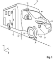
- a motor vehicle 10 in this case a mobile home, is shown.
- the motor vehicle 10 may be oriented at an angle relative to the horizontal plane.
- the oblique orientation of motor vehicle 10 means that motor vehicle 10 is pivoted out of the horizontal plane about its vehicle longitudinal direction x and/or about its vehicle transverse direction y.
- motor vehicle 10 has an orientation detection device 14, indicated schematically by a box, an electronic computing device 16 and, in the present case, an additional output device 18, indicated schematically by a box, a control device, indicated schematically by a box 20 and a detection device 22 indicated schematically with a box.
- a method diagram for a method for operating the motor vehicle 10 is shown, which allows compensation for the oblique orientation of the motor vehicle 10 relative to the horizontal plane.
- the method provides for the oblique orientation of motor vehicle 10 to be determined by means of orientation detection device 14 in a first method step V1.
- the orientation detection device 14 can have a gyroscope, by means of which a pivoting of the motor vehicle 10 about the vehicle longitudinal direction x and/or about the vehicle transverse direction y relative to the horizontal plane can be determined, which is the direction of application of the weight force and thus the weight force vector G of the motor vehicle 10 intersects perpendicularly.
- the spatial position and/or the geometry of the at least one compensating element 24 can be detected using the detection device 22 .
- the detection device 22 can have at least one camera, the field of view of which is aimed at the at least one compensation element 24 .
- a camera can be provided for each wheel 26 of motor vehicle 10, by means of which the respective wheel 26 and/or the compensating element 24 assigned to the respective wheel 26 can be recorded.
- the detection device 22 or the camera of the detection device 22 is arranged in a wheel housing of the motor vehicle 10 .
- At least one camera of detection device 22 can be arranged on an exterior mirror of motor vehicle 10 . Further alternative or additional arrangements of the at least one camera of detection device 22 on an outside of motor vehicle 10 are conceivable, such as in particular an arrangement of the at least one camera on a bumper or a rocker panel of motor vehicle 10. In particular, the at least one camera of detection device 22 can be set up for this purpose be to record the at least one compensation element 24 representing image data and to provide it for an image processing device.
- the image processing device can be used to determine dimensions and thus the geometry of the at least one compensation element 24 characterized by the image data and/or a relative spatial location and thus a relative position and/or a relative alignment of the at least one compensation element 24 characterized by the image data be determined relative to the motor vehicle 10, in particular relative to at least one wheel 26 of the motor vehicle 10.
- the geometry of the at least one compensating element 24 can alternatively or additionally be stored in a database of the electronic computing device 16.
- the geometry of the at least one compensating element 24 by means of the electronic Computing device 16 are received by an input device, the input device being set up to receive a user input characterizing the geometry of the compensating element 24 and to provide the geometry of the compensating element 24 characterized by the user input for the electronic computing device 16 .
- the electronic computing device 16 can be set up to store the geometry of the compensation element 24 received from the input device in the database.
- the electronic computing device 16 is also set up to determine a compensating distance in a third method step V3 depending on the determined oblique alignment of the motor vehicle 10 and the determined spatial position and geometry of the at least one compensating element 24 .
- This compensating path extends at least in certain areas over a surface of the at least one compensating element 24.
- the compensating path can represent a movement trajectory along which motor vehicle 10 is to be moved and is to be moved at least in certain areas over the surface of the at least one compensating element 24 in order to correct the oblique alignment of the To be able to compensate motor vehicle 10 and thus align motor vehicle 10 at least essentially in the horizontal plane, which means that both the vehicle longitudinal direction x and the vehicle transverse direction y run at least essentially parallel to the horizontal plane.
- the compensating distance is determined taking into account at least one boundary condition for the compensating distance.
- the boundary condition can be specified depending on the determined geometry of the at least one compensating element 24 .
- a maximum wedge length of the at least one compensating element 24 designed as a compensating wedge can specify a boundary condition for determining the compensating distance. This can prevent the motor vehicle 10 from driving off the compensating element 24 when moving along the compensating section due to its wheel 26 driving over an edge of the compensating element 24 .
- At least one limit condition for determining the compensating distance can be specified by a width of a surface of the at least one compensating element 24 that can be driven on by motor vehicle 10 . This can prevent the wheel 26 of the motor vehicle 10 from slipping sideways off the surface of the compensating element 24 .
- the compensating distance determined can be provided by the electronic computing device 16 for the output device 18 and/or for the control device 20.
- the compensating route determined can be output using output device 18, in the present case in the interior of motor vehicle 10.
- the driver of motor vehicle 10 can be informed about the compensating route determined by outputting the compensating route using output device 18 and can consequently guide motor vehicle 10 along the compensating route determined.
- the provision of the determined compensating section for the control device 20 enables the motor vehicle 10 to be guided along the compensating section at least partially automatically, in particular fully automatically and thus autonomously, by means of the control device 20 .
- the control device 20 can take over a lateral control and/or a longitudinal control of the motor vehicle 10 .
- the spatial position of the at least one compensation element 24 can be adjusted.
- electronic computing device 16 is used to determine the compensating distance that enables particularly good compensation of the oblique orientation of motor vehicle 10 while maintaining the boundary conditions provided by the at least one compensating element 24, with the compensating distance being freely selectable in terms of the relative spatial position of the compensating element 24 to the motor vehicle 10 is determined.
- the selected relative position and relative orientation of the at least one compensating element 24 to the motor vehicle 10 assigned to this determined compensating distance can be output by means of the output device 18, whereby a person can position the compensating element 24 in the specified relative position and relative orientation relative to the motor vehicle 10, in particular at least one wheel 26 of the Motor vehicle 10 can arrange.
- a user input characterizing a length of a route can be received by means of the electronic computing device 16 and made available for the control device 20 .
- the motor vehicle 10 can be moved at least partially automatically along the route for the length characterized by the user input.
- the invention described is based on the finding that driving a mobile home on compensating wedges as compensating elements 24 can be particularly tricky for a number of reasons.
- the gradient angle of the respective compensating wedge can be particularly steep and starting or gas metering should be particularly precise.
- the mobile home is to be driven to an exactly desired position in order to compensate for a given incline.
- Approaching the top wedge position of the compensating wedge can be particularly tricky, since the mobile home can fall off the back of the compensating wedge when the compensating wedge is driven over.
- At least one compensating wedge can be positioned in front of at least one wheel 26 of motor vehicle 10, and a person can specify a distance corresponding to the oblique orientation to be compensated, in particular for control device 20, which motor vehicle 10 is to drive up the at least one compensating wedge.
- This route can be covered by motor vehicle 10 in an automated manner and/or with assistance.
- the method described above allows motor vehicle 10 to use orientation detection device 14 to detect its current misalignment and thus the oblique alignment, and to raise the at least one compensating element 24 placed in front of at least one wheel 26 in the direction of travel until the oblique alignment relative to the horizontal plane is compensated.
- the motor vehicle 10 can take into account a maximum available wedge length of the respective compensating wedge in order to prevent motor vehicle 10 from falling behind the at least one compensating wedge with wheel 26 in the direction of travel.
- motor vehicle 10 can determine a suggestion for positioning the at least one compensating element 24 relative to motor vehicle 10 .
- This determined suggestion can be output via the output device 18 .
- a person in particular the driver, can position the at least one compensating element 24 according to the suggestion determined.
- the motor vehicle 10 can then automatically and/or with assistance raise the at least one compensating element 24 positioned by the person.
- Motor vehicle 10 uses the geometry of the at least one compensating wedge to take into account the maximum available wedge length of the at least one compensating wedge or to determine the proposal for positioning the at least one compensating wedge.
- This geometry of the at least one compensating wedge can be determined as a function of a user input, the user input representing at least a length and a height of the at least one compensating wedge.
- the geometry of the at least one compensating wedge can be used from the vehicle's own database.
- a large part of the variants of compensating wedges used in the field can be represented with just a few wedge models.
- a particularly large number of variants of compensating wedges can thus be represented in the database with a particularly small number of stored wedge models.
- the at least one compensating element 24 enables the oblique orientation of motor vehicle 10 to be compensated for in a particularly simple and convenient manner, in particular using particularly inexpensive and light compensating wedges as at least one compensating element 24.
- a position of a wheel 26 of the motor vehicle 10 on a compensating element 24 assigned to the wheel 26 that is detected by the detection device 22 can be made available via the output device 18 .
- An image of the wheel 26 captured by the capture device 22 can be output on the compensating element 24 by means of the output device 18, in particular for the driver of the motor vehicle 10.
- the invention shows how an assistance system for driving a mobile home on leveling wedges can be provided.
Abstract
Die Erfindung betrifft ein Verfahren zum Betreiben eines Kraftfahrzeugs (10), bei welchem mittels einer elektronischen Recheneinrichtung (16) eine eine Länge einer Wegstrecke charakterisierende Benutzereingabe empfangen wird und mittels einer Steuereinrichtung (20) das Kraftfahrzeug (10) zumindest teilautomatisiert die durch die Benutzereingabe charakterisierte Länge entlang der Wegstrecke bewegt wird, oder bei welchem mittels einer Orientierungserfassungseinrichtung (14) eine Schrägausrichtung des Kraftfahrzeugs (10) relativ zu einer Horizontalebene ermittelt wird, eine räumliche Lage und Geometrie wenigstens eines Ausgleichselements (24) ermittelt werden, auf welchem das Kraftfahrzeug (10) anordenbar ist, und mittels einer elektronischen Recheneinrichtung (16) in Abhängigkeit von der ermittelten Schrägausrichtung des Kraftfahrzeugs (10) und der ermittelten räumlichen Lage und Geometrie des wenigstens eines Ausgleichselements (24) eine Ausgleichsstrecke ermittelt und bereitgestellt wird, entlang welcher für ein Geraderichten des Kraftfahrzeugs (10) das Kraftfahrzeug (10) auf dem wenigstens einen Ausgleichselement (24) zu bewegen ist.The invention relates to a method for operating a motor vehicle (10), in which a user input characterizing a length of a route is received by means of an electronic computing device (16) and the motor vehicle (10) is at least partially automated by means of a control device (20) that is characterized by the user input length is moved along the route, or in which an oblique alignment of the motor vehicle (10) relative to a horizontal plane is determined by means of an orientation detection device (14), a spatial position and geometry of at least one compensating element (24) are determined, on which the motor vehicle (10 ) can be arranged, and using an electronic computing device (16) as a function of the determined oblique orientation of the motor vehicle (10) and the determined spatial position and geometry of the at least one compensation element (24) determines and provides a compensation section wi rd, along which for a straightening of the motor vehicle (10) the motor vehicle (10) on the at least one compensating element (24) is to be moved.
Description
Die Erfindung betrifft ein Verfahren zum Betreiben eines Kraftfahrzeugs sowie ein Kraftfahrzeug.The invention relates to a method for operating a motor vehicle and a motor vehicle.
Insbesondere bei einem Wohnmobil kann eine Schräglage unerwünscht sein. Es ist grundsätzlich bekannt, eine Schräglage eines Wohnmobils mittels wenigstens eines Ausgleichskeils auszugleichen, indem das Wohnmobil mit einem Rad auf dem Ausgleichskeil platziert wird. Hierbei kann es jedoch aufgrund einer schlechten Einsehbarkeit jeweiliger Räder des Wohnmobils von einem Fahrersitzplatz im Wohnmobil aus für den Fahrer des Wohnmobils sehr schwer sein, das jeweilige Rad präzise auf dem zugeordneten Ausgleichskeil zu platzieren.A sloping position can be undesirable, especially in a mobile home. It is known in principle to compensate for an inclined position of a camper by means of at least one compensating wedge by placing the camper with a wheel on the compensating wedge. Here, however, it can be very difficult for the driver of the motorhome to place the respective wheel precisely on the associated compensating wedge due to poor visibility of the respective wheels of the mobile home from a driver's seat in the mobile home.
Aus der
Aufgabe der vorliegenden Erfindung ist es, eine Lösung zu schaffen, welche ein besonders einfaches Ausgleichen einer Schrägstellung eines Kraftfahrzeugs durch Bewegen des Kraftfahrzeugs über wenigstens ein Ausgleichselement ermöglicht.It is the object of the present invention to create a solution which enables a particularly simple compensation of an inclined position of a motor vehicle by moving the motor vehicle via at least one compensation element.
Diese Aufgabe wird erfindungsgemäß durch die Gegenstände der unabhängigen Patentansprüche gelöst. Weitere mögliche Ausgestaltungen der Erfindung sind in den Unteransprüchen, der Beschreibung und den Figuren offenbart.According to the invention, this object is achieved by the subject matter of the independent patent claims. Further possible configurations of the invention are disclosed in the dependent claims, the description and the figures.
Die Erfindung betrifft ein Verfahren zum Betreiben eines Kraftfahrzeugs, bei welchem mittels einer elektronischen Recheneinrichtung eine eine Länge einer Wegstrecke charakterisierende Benutzereingabe empfangen wird und mittels einer Steuereinrichtung das Kraftfahrzeug zumindest teilautomatisiert die durch die Benutzereingabe charakterisierte Länge entlang der Wegstrecke bewegt wird. Das bedeutet, dass bei dem Verfahren eine Person die Wegstrecke für das Kraftfahrzeug über die Benutzereingabe vorgibt und das Kraftfahrzeug mittels der Steuereinrichtung für die vorgegebene Länge der Wegstrecke bewegt wird. Insbesondere bei einer Ausgestaltung des Kraftfahrzeugs als Wohnmobil, wenn das Wohnmobil auf wenigstens einem Ausgleichskeil für ein Ausgleichen einer Schräge anzuordnen ist, kann die Person vorgeben, wie weit das Wohnmobil entlang des Ausgleichskeils hochfahren soll. Die Person kann somit über die Benutzereingabe das besonders präzise Bewegen des Kraftfahrzeugs für die vorgegebene Länge auslösen.The invention relates to a method for operating a motor vehicle, in which a user input characterizing a length of a route is received by means of an electronic computing device and the motor vehicle is moved at least partially automatically by means of a control device along the length characterized by the user input. This means that in the process, a person covers the distance for the motor vehicle via the user input and the motor vehicle is moved by means of the control device for the predetermined length of the route. In particular when the motor vehicle is designed as a mobile home, if the mobile home is to be arranged on at least one compensating wedge to compensate for an incline, the person can specify how far the mobile home should go up along the compensating wedge. The person can thus use the user input to trigger the particularly precise movement of the motor vehicle for the specified length.
Alternativ wird bei dem Verfahren zum Betreiben des Kraftfahrzeugs mittels einer Orientierungserfassungseinrichtung eine Schrägausrichtung des Kraftfahrzeugs relativ zu einer Horizontalebene ermittelt wird. Mit anderen Worten wird mittels der Orientierungserfassungseinrichtung eine Verschwenkung des Kraftfahrzeugs um eine Fahrzeuglängsachse und/oder um eine Fahrzeugquerachse relativ zu der Horizontalebene ermittelt. Die Horizontalebene kann in ihrer Ausrichtung einen Gewichtskraftvektor des Kraftfahrzeugs senkrecht schneidend vorgegeben sein. Es wird somit mittels der Orientierungserfassungseinrichtung festgestellt, ob das Kraftfahrzeug schräg zur Horizontalebene ausgerichtet ist und damit um die Fahrzeuglängsachse und/oder die Fahrzeugquerachse relativ zur Horizontalebene verschwenkt ist. Bei dem Kraftfahrzeug kann es sich insbesondere um einen Kraftwagen handeln. Bei dem Kraftwagen kann es sich um einen Personenkraftwagen, insbesondere um ein Wohnmobil, handeln. Bei dem Verfahren ist es des Weiteren vorgesehen, dass eine räumliche Lage und Geometrie wenigstens eines Ausgleichselements ermittelt werden, auf welchem das Kraftfahrzeug anordenbar ist. Unter der räumlichen Lage ist insbesondere eine Position und Orientierung des Ausgleichselements zu verstehen, wobei die räumliche Lage insbesondere in Relation zu dem Kraftfahrzeug ermittelt wird. Bei dem Ausgleichselement kann es sich beispielsweise um einen Ausgleichskeil handeln, mittels welchem die Schrägausrichtung des Kraftfahrzeugs ausgleichbar ist. Die Schrägausrichtung des Kraftfahrzeugs kann insbesondere aus einer Unebenheit beziehungsweise einer Steigung eines Untergrunds, auf welchem das Kraftfahrzeug angeordnet ist, resultieren. Alternativ zu der Ausgestaltung des wenigstens einen Ausgleichselements als Ausgleichskeil kann das wenigstens eine Ausgleichselement als Rampe oder als Bühne ausgebildet sein. Insbesondere bei dem Wohnmobil ist es vorgesehen, dass die ermittelte Schrägstellung des Wohnmobils mittels des wenigstens einen Ausgleichselements hinsichtlich der Horizontalebene ausgeglichen wird.Alternatively, in the method for operating the motor vehicle, an oblique alignment of the motor vehicle relative to a horizontal plane is determined by means of an orientation detection device. In other words, a pivoting of the motor vehicle about a vehicle longitudinal axis and/or about a vehicle transverse axis relative to the horizontal plane is determined by means of the orientation detection device. The orientation of the horizontal plane can be predetermined so that it intersects a weight force vector of the motor vehicle perpendicularly. The orientation detection device is thus used to determine whether the motor vehicle is aligned at an angle to the horizontal plane and is therefore pivoted about the vehicle longitudinal axis and/or the vehicle transverse axis relative to the horizontal plane. The motor vehicle can in particular be a motor vehicle. The motor vehicle can be a passenger car, in particular a mobile home. The method also provides for the spatial position and geometry of at least one compensation element to be determined, on which the motor vehicle can be arranged. The spatial position is to be understood in particular as a position and orientation of the compensating element, with the spatial position being determined in particular in relation to the motor vehicle. The compensating element can be, for example, a compensating wedge, by means of which the oblique alignment of the motor vehicle can be compensated. The oblique alignment of the motor vehicle can result in particular from an unevenness or an incline of a subsurface on which the motor vehicle is arranged. As an alternative to the configuration of the at least one compensating element as a compensating wedge, the at least one compensating element can be configured as a ramp or as a platform. In the mobile home in particular, provision is made for the ascertained inclination of the mobile home to be compensated for by means of the at least one compensating element with respect to the horizontal plane.
Um ein besonders vorteilhaftes Ausgleichen der Schrägausrichtung des Kraftfahrzeugs mittels des wenigstens einen Ausgleichselements zu ermöglichen, ist es bei dem Verfahren vorgesehen, dass mittels einer elektronischen Recheneinrichtung in Abhängigkeit von der ermittelten Schrägausrichtung des Kraftfahrzeugs und der ermittelten räumlichen Lage und Geometrie des wenigstens einen Ausgleichselements eine Ausgleichsstrecke ermittelt und bereitgestellt wird. Die Ausgleichsstrecke kann zusätzlich in Abhängigkeit von einer Einfederung der Räder des Kraftfahrzeugs ermittelt werden. Entlang dieser Ausgleichsstrecke ist für ein Geraderichten des Kraftfahrzeugs das Kraftfahrzeug auf dem wenigstens einen Ausgleichselement zu bewegen. Unter dem Geraderichten des Kraftfahrzeugs ist ein Ausgleichen der Schrägausrichtung des Kraftfahrzeugs relativ zu der Horizontalebene und somit ein horizontales Ausrichten des Kraftfahrzeugs zu verstehen. Das wenigstens eine Ausgleichselement kann insbesondere wenigstens zwei zueinander schräg ausgerichtete Oberflächen aufweisen, wobei unter der schrägen Ausrichtung der Oberflächen zu verstehen ist, dass jeweilige durch die Oberflächen aufgespannte Ebenen sich unter einem spitzen Winkel miteinander schneiden. Über eine der Oberflächen kann das wenigstens eine Ausgleichselement auf dem Untergrund angeordnet werden, wobei die zu der auf dem Untergrund angeordneten Oberfläche schräge Oberfläche des wenigstens einen Ausgleichselements dazu eingerichtet ist, mit dem Kraftfahrzeug, insbesondere wenigstens einem Rad des Kraftfahrzeugs, kontaktiert zu werden, insbesondere für ein Auffahren des Kraftfahrzeugs entlang der Ausgleichsstrecke auf das wenigstens eine Ausgleichselement.In order to enable a particularly advantageous compensation of the oblique orientation of the motor vehicle by means of the at least one compensation element, it is in the method provided that a compensating section is determined and provided by means of an electronic computing device depending on the determined oblique orientation of the motor vehicle and the determined spatial position and geometry of the at least one compensating element. The compensating distance can also be determined as a function of a deflection of the wheels of the motor vehicle. To straighten the motor vehicle, the motor vehicle must be moved on the at least one compensating element along this compensating section. The straightening of the motor vehicle is to be understood as compensating for the oblique orientation of the motor vehicle relative to the horizontal plane and thus horizontally aligning the motor vehicle. The at least one compensating element can in particular have at least two surfaces aligned obliquely to one another, the oblique orientation of the surfaces meaning that the respective planes spanned by the surfaces intersect at an acute angle. The at least one compensating element can be arranged on the ground via one of the surfaces, wherein the surface of the at least one compensating element that is inclined relative to the surface arranged on the ground is set up to be in contact with the motor vehicle, in particular at least one wheel of the motor vehicle, in particular for a rear-end collision of the motor vehicle along the compensating section onto the at least one compensating element.
Um ein Auffahren des Kraftfahrzeugs entlang der Ausgleichsstrecke auf das wenigstens eine Ausgleichselement zu ermöglichen, ist es vorgesehen, dass das wenigstens eine Ausgleichselement in Fahrtrichtung vor wenigstens einem der Räder des Kraftfahrzeugs angeordnet ist, wobei die Ausgleichsstrecke in Abhängigkeit von der ermittelten räumlichen Lage und Geometrie des wenigstens einen in Fahrtrichtung vor wenigstens einem der Räder des Kraftfahrzeugs angeordneten Ausgleichselements ermittelt wird. Hierbei führt die Ausgleichsstrecke zumindest bereichsweise über eine Oberfläche des wenigstens einen Ausgleichselements, insbesondere über die schräg zu der auf dem Untergrund angeordneten Oberfläche ausgerichtete Oberfläche des Ausgleichselements. Das Verfahren ermöglicht ein besonders einfaches Ermitteln der Ausgleichsstrecke, entlang welcher das Kraftfahrzeug zu bewegen ist, um die Schrägausrichtung des Kraftfahrzeugs auszugleichen beziehungsweise das Kraftfahrzeug gerade zu richten.In order to enable the motor vehicle to drive onto the at least one compensating element along the compensating section, it is provided that the at least one compensating element is arranged in front of at least one of the wheels of the motor vehicle in the direction of travel, with the compensating section depending on the determined spatial position and geometry of the at least one compensating element arranged in front of at least one of the wheels of the motor vehicle in the direction of travel is determined. In this case, the compensating section leads at least in regions over a surface of the at least one compensating element, in particular over the surface of the compensating element which is oriented obliquely to the surface arranged on the substructure. The method enables a particularly simple determination of the compensating distance along which the motor vehicle is to be moved in order to compensate for the oblique orientation of the motor vehicle or to straighten the motor vehicle.
In einer Weiterbildung der Erfindung ist es vorgesehen, dass mittels einer Ausgabeeinrichtung die ermittelte Ausgleichsstrecke ausgegeben wird. Das bedeutet, dass bei dem Verfahren die mittels der elektronischen Recheneinrichtung ermittelte Ausgleichsstrecke mittels der elektronischen Recheneinrichtung für die Ausgabeeinrichtung bereitgestellt wird. Mittels der Ausgabeeinrichtung kann von der elektronischen Recheneinrichtung die ermittelte Ausgleichsstrecke empfangen und ausgegeben werden. Die Ausgabeeinrichtung kann Teil des Kraftfahrzeugs oder Teil eines mobilen elektronischen Endgeräts sein. Die Ausgabeeinrichtung kann dazu eingerichtet sein, die ermittelte Ausgleichsstrecke optisch und/oder akustisch und/oder haptisch auszugeben. Beispielsweise kann die Ausgabeeinrichtung als Bildschirmeinrichtung im Kraftfahrzeug ausgebildet sein, wodurch ein Fahrer des Kraftfahrzeugs mittels der Bildschirmeinrichtung besonders einfach über die ermittelte Ausgleichsstrecke informiert werden kann. Infolgedessen kann der Fahrer das Kraftfahrzeug entlang der Ausgleichsstrecke führen. Hierdurch ermöglicht das Verfahren ein besonders vorteilhaftes Unterstützen des Fahrers des Kraftfahrzeugs bei einem Manövrieren des Kraftfahrzeugs auf das wenigstens eine Ausgleichselement beziehungsweise bei dem Geraderichten des Kraftfahrzeugs durch Bewegen des Kraftfahrzeugs auf das wenigstens eine Ausgleichselement beziehungsweise auf dem wenigstens einen Ausgleichselement.In a further development of the invention, it is provided that the compensating distance determined is output by means of an output device. This means that in the method, the compensating distance determined by means of the electronic computing device is made available to the output device by means of the electronic computing device. by means of Output device can be received and output by the electronic computing device determined compensating distance. The output device can be part of the motor vehicle or part of a mobile electronic terminal device. The output device can be set up to output the compensation section determined optically and/or acoustically and/or haptically. For example, the output device can be embodied as a screen device in the motor vehicle, as a result of which a driver of the motor vehicle can be informed particularly easily about the compensation route that has been determined by means of the screen device. As a result, the driver can guide the motor vehicle along the compensating route. As a result, the method enables a particularly advantageous support of the driver of the motor vehicle when maneuvering the motor vehicle onto the at least one compensating element or when straightening the motor vehicle by moving the motor vehicle onto the at least one compensating element or on the at least one compensating element.
In weiterer Ausgestaltung der Erfindung ist es vorgesehen, dass mittels einer Steuereinrichtung das Kraftfahrzeug zumindest teilautomatisiert entlang der Ausgleichsstrecke bewegt wird. Das bedeutet, dass mittels der elektronischen Recheneinrichtung die ermittelte Ausgleichsstrecke für die Steuereinrichtung bereitgestellt wird. Somit wird mittels der Steuereinrichtung die von der elektronischen Recheneinrichtung bereitgestellte Ausgleichsstrecke empfangen und das Kraftfahrzeug entlang der Ausgleichsstrecke mittels der Steuereinrichtung gesteuert. Mittels der Steuereinrichtung kann das Kraftfahrzeug quergesteuert und/oder längsgesteuert werden. Insbesondere kann die Steuereinrichtung dazu eingerichtet sein, das Kraftfahrzeug autonom entlang der Ausgleichsstrecke zu bewegen. Das Bewegen des Kraftfahrzeugs mittels der Steuereinrichtung ermöglicht, dass das Kraftfahrzeug besonders präzise entlang der Ausgleichsstrecke bewegt wird.In a further embodiment of the invention, it is provided that the motor vehicle is moved at least partially automatically along the compensating section by means of a control device. This means that the compensating distance determined is made available to the control device by means of the electronic computing device. The compensating route provided by the electronic computing device is thus received by the control device and the motor vehicle is controlled along the compensating route by means of the control device. The motor vehicle can be controlled laterally and/or longitudinally by means of the control device. In particular, the control device can be set up to move the motor vehicle autonomously along the compensating route. Moving the motor vehicle using the control device makes it possible for the motor vehicle to be moved particularly precisely along the compensating section.
In einer weiteren Ausgestaltung der Erfindung ist es vorgesehen, dass in Abhängigkeit von der ermittelten Geometrie des wenigstens einen Ausgleichselements eine Grenzbedingung für die Ausgleichsstrecke ermittelt wird und die Ausgleichsstrecke in Abhängigkeit von der Grenzbedingung ermittelt wird. Hierbei kann die wenigstens eine Grenzbedingung in Abhängigkeit von jeweiligen Abmessungen einer von dem Kraftfahrzeug befahrbaren Oberfläche des wenigstens einen Ausgleichselements ermittelt werden. Beispielsweise kann ein Ende der Ausgleichsstrecke in Abhängigkeit von einer Länge der von dem Kraftfahrzeug zu befahrenden Oberfläche des wenigstens einen Ausgleichselements ermittelt werden. Hierdurch kann sichergestellt werden, dass ein Überfahren des wenigstens einen Ausgleichselements durch das Kraftfahrzeug unterbleibt. Beispielsweise kann bei der Ausgestaltung des wenigstens einen Ausgleichselements als Ausgleichskeil eine maximal zur Verfügung stehende Keillänge in das Ermitteln der Ausgleichsstrecke mit einbezogen werden. Hierdurch kann vermieden werden, dass das Kraftfahrzeug ungewünscht beim Fahren entlang der Ausgleichsstrecke von dem wenigstens einen Ausgleichselement herunterfährt.In a further embodiment of the invention, it is provided that a limit condition for the compensating section is determined as a function of the determined geometry of the at least one compensating element, and the compensating section is determined as a function of the limit condition. In this case, the at least one boundary condition can be determined as a function of the respective dimensions of a surface of the at least one compensating element that can be driven on by the motor vehicle. For example, an end of the compensating section can be determined as a function of a length of the surface of the at least one compensating element to be traveled over by the motor vehicle. In this way it can be ensured that the at least one compensating element is not driven over by the motor vehicle. For example, in the design of at least a compensating element as a compensating wedge, a maximum available wedge length can be included in the determination of the compensating section. In this way it can be avoided that the motor vehicle undesirably drives off the at least one compensating element when driving along the compensating section.
In einer weiteren Ausgestaltung der Erfindung ist vorgesehen, dass in Abhängigkeit von der ermittelten Ausgleichsstrecke für das wenigstens eine Ausgleichselement eine Soll-Lage ermittelt wird, in welcher das wenigstens eine Ausgleichselement relativ zu dem Kraftfahrzeug anzuordnen ist, wodurch das Kraftfahrzeug entlang der ermittelten Ausgleichsstrecke bewegbar ist, und die ermittelte Soll-Lage mittels der Ausgabeeinrichtung ausgegeben wird. Insbesondere wird die ermittelte Soll-Lage relativ zu wenigstens einem Rad des Kraftfahrzeugs vorgegeben. Diese Soll-Lage kann in Abhängigkeit von einer Einfederung der Räder des Kraftfahrzeugs ermittelt werden. Das Ausgeben der ermittelten Solllage des wenigstens einen Ausgleichselements mittels der Ausgabeeinrichtung ermöglicht, dass der Fahrer des Kraftfahrzeugs oder ein weiterer Fahrzeuginsasse des Kraftfahrzeugs das wenigstens eine Ausgleichselement in der ermittelten Soll-Lage und somit in der vorgegebenen Sollposition und Sollorientierung relativ zu dem wenigstens einen Rad des Kraftfahrzeugs anordnen kann. Bei dem Verfahren kann somit ermittelt werden, an welcher Relativposition und in welcher relativen Orientierung das wenigstens eine Ausgleichselement relativ zu wenigstens einem der Räder des Kraftfahrzeugs auszurichten ist, um eine Ausgleichsstrecke ermitteln zu können, welche ein Geradestellen des Kraftfahrzeugs beziehungsweise ein besonders gutes Ausgleichen der Schrägausrichtung des Kraftfahrzeugs relativ zu der Horizontalebene ermöglicht. Es kann somit bei dem Verfahren in Abhängigkeit von der gegebenen Geometrie des wenigstens einen Ausgleichselements, welches für ein Ausgleichen der Schrägausrichtung des Kraftfahrzeugs zur Verfügung steht, diejenige Ausgleichsstrecke ermittelt werden, welche ein besonders gutes Ausgleichen der Schrägausrichtung des Kraftfahrzeugs zu der Horizontalebene ermöglicht. Hierbei kann beim Ermitteln einer optimalen Ausgleichsstrecke die räumliche Lage des wenigstens einen Ausgleichselements zu dem wenigstens einen Rad des Kraftfahrzeugs frei wählbar sein. Ist diese besonders vorteilhafte Ausgleichsstrecke ermittelt worden, dann wird in Abhängigkeit von dieser ermittelten besonders vorteilhaften Ausgleichsstrecke die räumliche Lage des wenigstens einen Ausgleichselements relativ zu dem wenigstens einen Rad des Kraftfahrzeugs ermittelt, welche einzuhalten ist, um ein Bewegen des Kraftfahrzeugs entlang dieser ermittelten besonders vorteilhaften Ausgleichsstrecke zu ermöglichen. Diese ermittelte räumliche Lage des wenigstens einen Ausgleichselements relativ zu dem wenigstens einen Rad des Kraftfahrzeugs kann mittels der Ausgabeeinrichtung ausgegeben werden, wodurch der Fahrer und/oder ein Fahrzeuginsasse des Kraftfahrzeugs die ermittelte räumliche Lage des wenigstens einen Ausgleichselements einstellen kann. Hierdurch kann ein besonders gutes Ausgleichen der Schrägausrichtung des Kraftfahrzeugs relativ zu der Horizontalebene, insbesondere bis zu einer geraden Anordnung des Kraftfahrzeugs in der Horizontalebene, ermöglicht werden.In a further embodiment of the invention, it is provided that, depending on the compensating distance determined, a target position is determined for the at least one compensating element, in which position the at least one compensating element is to be arranged relative to the motor vehicle, as a result of which the motor vehicle can be moved along the compensating distance determined , and the determined target position is output by means of the output device. In particular, the determined target position is specified relative to at least one wheel of the motor vehicle. This target position can be determined depending on a deflection of the wheels of the motor vehicle. Outputting the determined target position of the at least one compensating element by means of the output device enables the driver of the motor vehicle or another vehicle occupant of the motor vehicle to position the at least one compensating element in the determined target position and thus in the specified target position and target orientation relative to the at least one wheel of the Motor vehicle can arrange. In the method, it can thus be determined at which relative position and in which relative orientation the at least one compensating element is to be aligned relative to at least one of the wheels of the motor vehicle in order to be able to determine a compensating distance which enables the motor vehicle to be straightened or a particularly good compensation of the inclined alignment of the motor vehicle allows relative to the horizontal plane. Depending on the given geometry of the at least one compensating element, which is available for compensating for the oblique orientation of the motor vehicle, the method can thus be used to determine that compensating distance which enables particularly good compensation of the oblique orientation of the motor vehicle with respect to the horizontal plane. When determining an optimal compensating distance, the spatial position of the at least one compensating element relative to the at least one wheel of the motor vehicle can be freely selectable. If this particularly advantageous compensating section has been determined, then the spatial position of the at least one compensating element relative to the at least one wheel of the motor vehicle is determined as a function of this determined particularly advantageous compensating section, which must be maintained in order to move the motor vehicle along this determined particularly advantageous compensating section to allow. This determined spatial position of the at least one compensating element relative to the at least one wheel of the motor vehicle can be output by means of the output device, whereby the driver and/or a vehicle occupant of the motor vehicle can see the determined spatial position of the can adjust at least one compensating element. This allows a particularly good compensation of the oblique orientation of the motor vehicle relative to the horizontal plane, in particular up to a straight arrangement of the motor vehicle in the horizontal plane.
In weiterer Ausgestaltung der Erfindung ist vorgesehen, dass mittels der elektronischen Recheneinrichtung die Geometrie des wenigstens einen Ausgleichselements in Abhängigkeit von einer die Geometrie charakterisierenden, mittels einer Eingabeeinrichtung erfassten Benutzereingabe ermittelt wird und/oder mittels der elektronischen Recheneinrichtung die Geometrie des wenigstens einen Ausgleichselements über eine in der elektronischen Recheneinrichtung hinterlegte Datenbank ermittelt wird. Das bedeutet, dass die Geometrie des wenigstens einen Ausgleichselements in der Datenbank in der elektronischen Recheneinrichtung hinterlegt sein kann und die elektronische Recheneinrichtung für das Ermitteln der Ausgleichsstrecke auf die in der Datenbank hinterlegte Geometrie des wenigstens einen Ausgleichselements zurückgreifen kann. Alternativ oder zusätzlich kann über die Eingabeeinrichtung eine Person die Geometrie des wenigstens einen Ausgleichselements durch die Benutzereingabe repräsentiert für die elektronische Recheneinrichtung bereitstellen. Die Eingabeeinrichtung kann Teil des Kraftfahrzeugs sein oder Teil eines mobilen elektronischen Endgeräts wie beispielsweise eines Mobiltelefons oder eines Tabletcomputers und/oder eines Laptops sein. Die Eingabeeinrichtung ist dazu eingerichtet, die durch die Benutzereingabe repräsentierte Geometrie des wenigstens einen Ausgleichselements für die elektronische Recheneinrichtung bereitzustellen. In der elektronischen Recheneinrichtung kann die von der Eingabeeinrichtung empfangene Geometrie des wenigstens einen Ausgleichselements dem Ausgleichselement zugeordnet gespeichert werden. Insbesondere kann die von der Eingabeeinrichtung empfangene Geometrie des wenigstens einen Ausgleichselements dem Ausgleichselement zugeordnet in der Datenbank hinterlegt werden. Hierdurch kann sichergestellt werden, dass der elektronischen Recheneinrichtung die Geometrie des wenigstens einen Ausgleichselements für das Ermitteln der Ausgleichsstrecke zur Verfügung steht.In a further embodiment of the invention, it is provided that the electronic computing device is used to determine the geometry of the at least one compensating element as a function of a user input characterizing the geometry and recorded using an input device and/or the electronic computing device is used to determine the geometry of the at least one compensating element via an in the database stored in the electronic computing device is determined. This means that the geometry of the at least one compensating element can be stored in the database in the electronic computing device and the electronic computing device can access the geometry of the at least one compensating element stored in the database to determine the compensating section. Alternatively or additionally, a person can use the input device to provide the geometry of the at least one compensation element represented by the user input for the electronic computing device. The input device can be part of the motor vehicle or part of a mobile electronic terminal such as a mobile phone or a tablet computer and/or a laptop. The input device is set up to provide the geometry of the at least one compensation element represented by the user input for the electronic computing device. The geometry of the at least one compensating element received from the input device can be stored in the electronic computing device in association with the compensating element. In particular, the geometry of the at least one compensation element received from the input device and assigned to the compensation element can be stored in the database. This can ensure that the geometry of the at least one compensating element is available to the electronic computing device for determining the compensating section.
Die Erfindung betrifft des Weiteren ein Kraftfahrzeug, welches dazu eingerichtet ist, ein Verfahren, wie es bereits im Zusammenhang mit dem erfindungsgemäßen Verfahren beschrieben worden ist, durchzuführen. Hierfür umfasst das Kraftfahrzeug eine elektronischen Recheneinrichtung, welche dazu eingerichtet ist, eine eine Länge einer Wegstrecke charakterisierende Benutzereingabe zu empfangen und eine Steuereinrichtung, welche dazu eingerichtet ist, das Kraftfahrzeug zumindest teilautomatisiert die durch die Benutzereingabe charakterisierte Länge entlang der Wegstrecke zu bewegen. Über die elektronische Recheneinrichtung kann eine Person mittels der Benutzereingabe die Länge der Wegstrecke vorgeben, für welche das Kraftfahrzeug zu bewegen ist. Insbesondere bei einer Ausgestaltung des Kraftfahrzeugs als Wohnwagen kann sich die Wegstrecke zumindest bereichsweise über eine Oberfläche des wenigstens einen Ausgleichselement erstrecken. Somit kann die Person dem Kraftfahrzeug über die Benutzereingabe vorgeben, wie weit dieses sich über die Oberfläche des wenigstens einen Ausgleichselement bewegen soll, wodurch eine Schräglage des Kraftfahrzeugs ausgeglichen werden kann. Hierdurch ist die Schräglage besonders einfach ausgleichbar.The invention also relates to a motor vehicle which is set up to carry out a method as has already been described in connection with the method according to the invention. For this purpose, the motor vehicle comprises an electronic computing device, which is set up to receive a user input characterizing a length of a route, and a control device, which is set up to at least partially automate the motor vehicle by the user input to move characterized length along the route. Using the electronic computing device, a person can use the user input to specify the length of the route for which the motor vehicle is to be moved. In particular when the motor vehicle is designed as a caravan, the route can extend at least in regions over a surface of the at least one compensating element. The person can thus use the user input to specify to the motor vehicle how far it should move over the surface of the at least one compensating element, as a result of which an inclined position of the motor vehicle can be compensated for. As a result, the inclined position can be compensated for in a particularly simple manner.
Alternativ oder zusätzlich umfasst das Kraftfahrzeug eine Orientierungserfassungseinrichtung, welche dazu eingerichtet ist, eine Schrägausrichtung des Kraftfahrzeugs relativ zu einer Horizontalebene zu ermitteln. Zum Ermitteln der Schrägausrichtung des Kraftfahrzeugs kann die Orientierungserfassungseinrichtung beispielsweise ein Kreiselinstrument umfassen. Mittels der Orientierungserfassungseinrichtung ist ein Verschwenken beziehungsweise eine Verschwenkung des Kraftfahrzeugs um die Fahrzeuglängsachse und/oder um die Fahrzeugquerachse aus der Horizontalebene heraus ermittelbar. In dieser alternativen oder zusätzlichen Ausgestaltung umfasst das Kraftfahrzeug die elektronische Recheneinrichtung, welche dazu eingerichtet ist, eine räumliche Lage und Geometrie wenigstens eines Ausgleichselements, auf welchem das Kraftfahrzeug anordenbar ist, zu ermitteln. Weiterhin ist die elektronische Recheneinrichtung dazu eingerichtet, in Abhängigkeit von der ermittelten Schrägausrichtung des Kraftfahrzeugs und der ermittelten räumlichen Lage und Geometrie des wenigstens einen Ausgleichselements eine Ausgleichsstrecke zu ermitteln und bereitzustellen. Entlang der Ausgleichsstrecke ist für ein Geraderichten des Kraftfahrzeugs das Kraftfahrzeug auf dem wenigstens einen Ausgleichselement zu bewegen. Unter dem Geraderichten des Kraftfahrzeugs ist zu verstehen, dass das Kraftfahrzeug in die Horizontalebene durch Rotation um die Fahrzeuglängsrichtung und/oder Fahrzeugquerrichtung hinein verschwenkt wird. Die elektronische Recheneinrichtung ist insbesondere dazu eingerichtet, die ermittelte Ausgleichsstrecke für eine Ausgabeeinrichtung und/oder eine Steuereinrichtung bereitzustellen. Hierdurch wird ermöglicht, dass das Kraftfahrzeug entlang der Ausgleichsstrecke bewegt wird, wodurch das Kraftfahrzeug gerade gerichtet werden kann. Das Kraftfahrzeug ist somit besonders einfach gerade richtbar, was insbesondere vorteilhaft ist, wenn das Kraftfahrzeug als Wohnmobil ausgebildet ist.Alternatively or additionally, the motor vehicle includes an orientation detection device which is set up to determine an oblique orientation of the motor vehicle relative to a horizontal plane. To determine the oblique orientation of the motor vehicle, the orientation detection device can include a gyroscope, for example. Pivoting or pivoting of the motor vehicle about the vehicle longitudinal axis and/or about the vehicle transverse axis from the horizontal plane can be determined by means of the orientation detection device. In this alternative or additional configuration, the motor vehicle includes the electronic computing device, which is set up to determine a spatial position and geometry of at least one compensation element on which the motor vehicle can be arranged. Furthermore, the electronic computing device is set up to determine and provide a compensating section as a function of the determined oblique orientation of the motor vehicle and the determined spatial position and geometry of the at least one compensating element. To straighten the motor vehicle along the compensating section, the motor vehicle must be moved on the at least one compensating element. The straightening of the motor vehicle is to be understood as meaning that the motor vehicle is pivoted into the horizontal plane by rotation about the vehicle longitudinal direction and/or the vehicle transverse direction. The electronic arithmetic unit is set up in particular to provide the determined compensating section for an output device and/or a control device. This makes it possible for the motor vehicle to be moved along the compensating section, as a result of which the motor vehicle can be straightened. The motor vehicle can thus be straightened particularly easily, which is particularly advantageous if the motor vehicle is designed as a mobile home.
In einer Weiterbildung der Erfindung ist vorgesehen, dass das Kraftfahrzeug zusätzlich die Ausgabeeinrichtung umfasst, welche dazu eingerichtet ist, die ermittelte Ausgleichsstrecke von der elektronischen Recheneinrichtung zu empfangen und auszugeben. Für das Ausgeben der Ausgleichsstrecke kann die Ausgabeeinrichtung eine Bildschirmeinrichtung umfassen, auf welcher die ermittelte Ausgleichsstrecke anzeigbar ist. Das Ausgeben der ermittelten Ausgleichsstrecke mittels der Ausgabeeinrichtung ermöglicht, dass ein Fahrer des Kraftfahrzeugs besonders einfach und besonders genau über einen Verlauf der Ausgleichsstrecke informiert werden kann, wodurch der Fahrer das Kraftfahrzeug entlang der Ausgleichsstrecke führen kann.In a further development of the invention it is provided that the motor vehicle additionally includes the output device, which is set up to the determined compensating distance from to receive and output the electronic computing device. To output the compensating section, the output device can include a screen device on which the compensating section that has been determined can be displayed. Outputting the calculated compensating route by means of the output device enables a driver of the motor vehicle to be informed particularly easily and precisely about the course of the compensating route, as a result of which the driver can guide the motor vehicle along the compensating route.
In weiterer Ausgestaltung der Erfindung ist es vorgesehen, dass das Kraftfahrzeug die Steuereinrichtung umfasst, welche dazu eingerichtet ist, die Ausgleichsstrecke von der elektronischen Recheneinrichtung zu empfangen und das Kraftfahrzeug zumindest teilautomatisiert, insbesondere vollautomatisiert, entlang der Ausgleichsstrecke zu bewegen. Die Steuereinrichtung ermöglicht somit ein zumindest teilautomatisiertes Geraderichten des Kraftfahrzeugs durch Bewegen des Kraftfahrzeugs entlang der Ausgleichsstrecke. Mittels der Steuereinrichtung ist das Kraftfahrzeug besonders präzise entlang der Ausgleichsrichtung bewegbar, wodurch ein unbeabsichtigtes Herunterfahren von dem wenigstens einen Ausgleichselement zumindest im Wesentlichen vermieden werden kann. Weiterhin ermöglicht das zumindest teilautomatisierte Bewegen des Kraftfahrzeugs entlang der Ausgleichsstrecke ein für den Fahrer des Kraftfahrzeugs besonders komfortables Geraderichten des Kraftfahrzeugs.In a further embodiment of the invention, it is provided that the motor vehicle includes the control device, which is set up to receive the compensating route from the electronic computing device and to move the motor vehicle along the compensating route at least partially automatically, in particular fully automatically. The control device thus enables at least partially automated straightening of the motor vehicle by moving the motor vehicle along the compensating section. The motor vehicle can be moved particularly precisely along the compensation direction by means of the control device, as a result of which unintentional lowering of the at least one compensation element can be at least essentially avoided. Furthermore, the at least partially automated movement of the motor vehicle along the compensating section enables straightening of the motor vehicle, which is particularly convenient for the driver of the motor vehicle.
In weiterer Ausgestaltung der Erfindung ist vorgesehen, dass das Kraftfahrzeug zusätzlich eine Erfassungseinrichtung umfasst, welche dazu eingerichtet ist, die Geometrie und/oder die räumliche Lage des wenigstens einen Ausgleichselements zu erfassen. Hierbei können entweder die Erfassungseinrichtung und/oder die elektronische Recheneinrichtung dazu eingerichtet sein, in Abhängigkeit von der erfassten Geometrie und/oder in Abhängigkeit von der räumlichen Lage des wenigstens einen Ausgleichselements eine Relativlage und somit eine Relativposition und Relativausrichtung des wenigstens einen Ausgleichselements zu dem Kraftfahrzeug, insbesondere zu wenigstens einem Rad des Kraftfahrzeugs zu ermitteln. Hierfür kann die Erfassungseinrichtung dazu eingerichtet sein, die erfasste Geometrie und/oder räumliche Lage des wenigstens einen Ausgleichselements für die elektronische Recheneinrichtung bereitzustellen. In Abhängigkeit von der mittels der Erfassungseinrichtung erfassten räumlichen Lage und/oder Geometrie des wenigstens einen Ausgleichselements kann die elektronische Recheneinrichtung dazu eingerichtet sein, die Ausgleichsstrecke zu ermitteln. Alternativ oder zusätzlich kann die Erfassungseinrichtung dazu eingerichtet sein, die erfasste Geometrie und/oder räumliche Lage des wenigstens einen Ausgleichselements für die Ausgabeeinrichtung bereitzustellen, mittels welcher die empfangene Geometrie und/oder räumliche Lage des wenigstens einen Ausgleichselements ausgebbar ist. Durch das Ausgeben der erfassten Geometrie und/oder räumlichen Lage des wenigstens einen Ausgleichselements mittels der Ausgabeeinrichtung kann der Fahrer über die mittels der Erfassungseinrichtung erfasste räumliche Lage und/oder Geometrie des wenigstens einen Ausgleichselements besonders einfach und genau informiert werden. Hierdurch kann der Fahrer das Kraftfahrzeug besonders informiert auf der Oberfläche des wenigstens einen Ausgleichselements für das Geraderichten des Kraftfahrzeugs bewegen. Eine Gefahr eines unbeabsichtigten Herunterfahrens des Kraftfahrzeugs von dem wenigstens einen Ausgleichselement beim Steuern des Kraftfahrzeugs durch den Fahrer kann hierdurch besonders gering gehalten werden.In a further embodiment of the invention, it is provided that the motor vehicle additionally comprises a detection device which is set up to detect the geometry and/or the spatial position of the at least one compensation element. In this case, either the detection device and/or the electronic computing device can be set up to determine a relative position and thus a relative position and relative alignment of the at least one compensation element to the motor vehicle, depending on the geometry detected and/or depending on the spatial position of the at least one compensation element. in particular to determine at least one wheel of the motor vehicle. For this purpose, the detection device can be set up to provide the detected geometry and/or spatial position of the at least one compensation element for the electronic computing device. Depending on the spatial position and/or geometry of the at least one compensating element detected by the detection device, the electronic computing device can be set up to determine the compensating section. Alternatively or additionally, the detection device can be set up to the detected geometry and / or spatial position of the at least one compensation element for Provide output device, by means of which the received geometry and / or spatial position of the at least one compensation element can be output. By outputting the recorded geometry and/or spatial position of the at least one compensating element using the output device, the driver can be informed particularly easily and precisely about the spatial position and/or geometry of the at least one compensating element recorded using the recording device. As a result, the driver can move the motor vehicle in a particularly informed manner on the surface of the at least one compensating element for straightening the motor vehicle. A risk of the motor vehicle being driven down unintentionally by the at least one compensating element when the driver is controlling the motor vehicle can be kept particularly low as a result.
Das Kraftfahrzeug kann in einer unabhängigen Ausgestaltung oder in einer unterstützenden Weiterbildung eine Wegstreckenzähleinrichtung umfassen, welche dazu eingerichtet ist, eine von dem Kraftfahrzeug, insbesondere dem als Wohnmobil ausgebildeten Kraftfahrzeug, zurückgelegte Strecke zu ermitteln und die ermittelte zurückgelegte Strecke für eine Anzeigeeinrichtung bereitzustellen. Hierbei ist es insbesondere vorgesehen, dass die Wegstreckenzähleinrichtung die zurückgelegte Strecke auf Dezimeter und/oder auf Zentimeter und/oder auf Millimeter genau ermittelt. Alternativ kann die Wegstreckenzähleinrichtung dazu eingerichtet sein, die Strecke in einer weiteren Längenmaßeinheit in der Größenordnung von Millimetern, Zentimetern oder Dezimetern, wie Zoll oder Inch, zu ermitteln. Weiterhin kann das Kraftfahrzeug die Anzeigeeinrichtung umfassen, welche dazu eingerichtet ist, die von der Wegstreckenzähleinrichtung ermittelte Strecke auszugeben, insbesondere auf Millimeter oder Zentimeter oder Dezimeter genau. Alternativ kann die Anzeigeeinrichtung dazu ausgebildet sein, die ermittelte Strecke in der weiteren Längenmaßeinheit auszugeben. Mittels der Anzeigeeinrichtung kann somit ein Fahrzeuginsasse besonders präzise über die mittels des Kraftfahrzeugs zurückgelegte Strecke informiert werden. Hierdurch kann ein Fahrer des Kraftfahrzeugs besonders genau steuern. Insbesondere kann der Fahrer das als Wohnmobil ausgebildete Kraftfahrzeug besonders genau auf wenigstens einem Ausgleichselement platzieren, wodurch eine Schräglage des Kraftfahrzeugs von dem Fahrer besonders unkompliziert ausgeglichen werden kann.In an independent configuration or in a supporting development, the motor vehicle can comprise an odometer device which is set up to determine a distance traveled by the motor vehicle, in particular the motor vehicle designed as a mobile home, and to provide the determined distance traveled for a display device. It is provided here in particular that the distance-counting device determines the distance covered to the nearest decimeter and/or to the centimeter and/or to the millimeter. Alternatively, the distance counting device can be set up to determine the distance in a further unit of length in the order of millimeters, centimeters or decimeters, such as inches or inches. Furthermore, the motor vehicle can include the display device, which is set up to output the route determined by the odometer device, in particular with an accuracy of millimeters or centimeters or decimeters. Alternatively, the display device can be designed to output the determined distance in the further unit of length. A vehicle occupant can thus be informed particularly precisely about the route covered by the motor vehicle by means of the display device. As a result, a driver of the motor vehicle can steer particularly precisely. In particular, the driver can place the motor vehicle designed as a mobile home particularly precisely on at least one compensating element, as a result of which an inclined position of the motor vehicle can be compensated for by the driver in a particularly uncomplicated manner.
Weitere Merkmale der Erfindung können sich aus der nachfolgenden Figurenbeschreibung sowie anhand der Zeichnung ergeben. Die vorstehend in der Beschreibung genannten Merkmale und Merkmalskombinationen sowie die nachfolgend in der Figurenbeschreibung und/oder in den Figuren alleine gezeigten Merkmale und Merkmalskombinationen sind nicht nur in der jeweils angegebenen Kombination, sondern auch in anderen Kombinationen oder in Alleinstellung verwendbar, ohne den Rahmen der Erfindung zu verlassen.Further features of the invention can result from the following description of the figures and from the drawing. The features and feature combinations mentioned above in the description and the features and feature combinations shown below in the description of the figures and/or in the figures alone are not only in the combination specified in each case, but also in other combinations or on its own, without departing from the scope of the invention.
Dabei zeigt die Zeichnung in:
- Fig. 1
- eine schematische Perspektivansicht eines Kraftfahrzeugs, vorliegend eines Wohnmobils, dessen wenigstens eines Rad auf einem Ausgleichselement angeordnet ist, wodurch das Kraftfahrzeug relativ zu einer Horizontalebene gerade gerichtet ist; und
- Fig. 2
- ein Verfahrensschema für ein Verfahren zum Betreiben des Kraftfahrzeugs, bei welchem eine Schrägausrichtung des Kraftfahrzeugs relativ zu der Horizontalebene ermittelt wird, eine räumliche Lage und Geometrie des wenigstens einen Ausgleichselements ermittelt wird und eine Ausgleichsstrecke in Abhängigkeit von der Schrägausrichtung und in Abhängigkeit von der ermittelten räumliche Lage und Geometrie des wenigstens einen Ausgleichselements ermittelt wird, entlang welcher das Kraftfahrzeug zumindest bereichsweise über eine Oberfläche des wenigstens einen Ausgleichselements bewegt wird, um die ermittelte Schrägausrichtung auszugleichen und somit das Kraftfahrzeug gerade zu richten.
- 1
- a schematic perspective view of a motor vehicle, in this case a mobile home, the at least one wheel of which is arranged on a compensating element, as a result of which the motor vehicle is straightened relative to a horizontal plane; and
- 2
- a process diagram for a method for operating the motor vehicle, in which an inclined orientation of the motor vehicle relative to the horizontal plane is determined, a spatial position and geometry of the at least one compensation element is determined and a compensation section depending on the inclined orientation and depending on the determined spatial position and Geometry of the at least one compensating element is determined, along which the motor vehicle is moved at least in regions over a surface of the at least one compensating element in order to compensate for the oblique orientation determined and thus to straighten the motor vehicle.
In
In
Die elektronische Recheneinrichtung 16 ist weiterhin dazu eingerichtet, in einem dritten Verfahrensschritt V3 in Abhängigkeit von der ermittelten Schrägausrichtung des Kraftfahrzeugs 10 und der ermittelten räumliche Lage und Geometrie des wenigstens einen Ausgleichselements 24 eine Ausgleichsstrecke zu ermitteln. Diese Ausgleichsstrecke erstreckt sich zumindest bereichsweise über eine Oberfläche des wenigstens einen Ausgleichselements 24. Die Ausgleichsstrecke kann eine Bewegungstrajektorie repräsentieren, entlang welcher das Kraftfahrzeug 10 zu bewegen ist und dabei zumindest bereichsweise über die Oberfläche des wenigstens einen Ausgleichselements 24 zu bewegen ist, um die Schrägausrichtung des Kraftfahrzeugs 10 ausgleichen zu können und somit das Kraftfahrzeug 10 zumindest im Wesentlichen in die Horizontalebene auszurichten, worunter zu verstehen ist, dass sowohl die Fahrzeuglängsrichtung x als auch die Fahrzeugquerrichtung y zumindest im Wesentlichen parallel zur Horizontalebene verlaufen. Um ein Herunterfahren des Kraftfahrzeugs 10 von dem wenigstens einen Ausgleichselement 24 beim Geraderichten des Kraftfahrzeugs 10 zumindest im Wesentlichen unterbinden zu können, ist es vorgesehen, dass die Ausgleichsstrecke unter Berücksichtigung wenigstens einer Grenzbedingung für die Ausgleichsstrecke ermittelt wird. Die Grenzbedingung kann in Abhängigkeit von der ermittelten Geometrie des wenigstens einen Ausgleichselements 24 vorgegeben sein. Insbesondere kann eine maximale Keillänge des als Ausgleichskeil ausgebildeten wenigstens einen Ausgleichselements 24 eine Grenzbedingung für das Ermitteln der Ausgleichsstrecke vorgeben. Hierdurch kann vermieden werden, dass das Kraftfahrzeug 10 beim Bewegen entlang der Ausgleichsstrecke aufgrund eines Überfahrens einer Kante des Ausgleichselements 24 mit seinem Rad 26 von dem Ausgleichselement 24 herunterfährt. Weiterhin kann durch eine Breite einer von dem Kraftfahrzeug 10 befahrbaren Oberfläche des wenigstens einen Ausgleichselements 24 wenigstens eine Grenzbedingung für das Ermitteln der Ausgleichsstrecke vorgegeben werden. Hierdurch kann einem seitlichen Abrutschen des Rads 26 des Kraftfahrzeugs 10 von der Oberfläche des Ausgleichselements 24 vorgebeugt werden.The
In dem dritten Verfahrensschritt V3 kann die ermittelte Ausgleichsstrecke mittels der elektronischen Recheneinrichtung 16 für die Ausgabeeinrichtung 18 und/oder für die Steuereinrichtung 20 bereitgestellt werden. Mittels der Ausgabeeinrichtung 18 ist die ermittelte Ausgleichsstrecke ausgebbar, vorliegend im Innenraum des Kraftfahrzeugs 10. Über das Ausgeben der ermittelten Ausgleichsstrecke mittels der Ausgabeeinrichtung 18 kann der Fahrer des Kraftfahrzeugs 10 über die ermittelte Ausgleichsstrecke informiert werden und infolgedessen das Kraftfahrzeug 10 entlang der ermittelten Ausgleichsstrecke führen. Das Bereitstellen der ermittelten Ausgleichsstrecke für die Steuereinrichtung 20 ermöglicht, dass mittels der Steuereinrichtung 20 das Kraftfahrzeug 10 zumindest teilautomatisiert, insbesondere vollautomatisiert und damit autonom, entlang der Ausgleichsstrecke geführt werden kann. Hierfür kann die Steuereinrichtung 20 eine Quersteuerung und/oder eine Längssteuerung des Kraftfahrzeugs 10 übernehmen.In the third method step V3, the compensating distance determined can be provided by the
Um eine Ausgleichsstrecke ermitteln zu können, durch das Abfahren von welcher das Kraftfahrzeug 10 in seiner Schrägausrichtung besonders gut korrigiert werden kann und damit mit besonders hoher Sicherheit gerade zur Horizontalebene ausgerichtet werden kann, und durch welche gleichzeitig durch die Geometrie des wenigstens einen Ausgleichselements 24 vorgegebene Grenzbedingungen eingehalten werden können, kann die räumliche Lage des wenigstens einen Ausgleichselements 24 angepasst werden. Hierfür ist es vorgesehen, dass mittels der elektronischen Recheneinrichtung 16 die Ausgleichsstrecke ermittelt wird, welche ein besonders gutes Ausgleichen der Schrägausrichtung des Kraftfahrzeugs 10 bei Einhaltung der durch das wenigstens eine Ausgleichselement 24 vorgesehenen Grenzbedingungen ermöglicht wird, wobei die Ausgleichsstrecke bei freier Wahl der relativen räumliche Lage des Ausgleichselements 24 zu dem Kraftfahrzeug 10 ermittelt wird. Die dieser ermittelten Ausgleichsstrecke zugeordnete gewählte Relativposition und Relativausrichtung des wenigstens einen Ausgleichselements 24 zu dem Kraftfahrzeug 10 kann mittels der Ausgabeeinrichtung 18 ausgegeben werden, wodurch eine Person das Ausgleichselement 24 in der vorgegebenen Relativposition und Relativausrichtung relativ zu dem Kraftfahrzeug 10, insbesondere wenigstens einem Rad 26 des Kraftfahrzeugs 10, anordnen kann. Hierdurch wird ermöglicht, dass das Kraftfahrzeug 10 entlang der mittels der elektronischen Recheneinrichtung 16 unter Einhaltung der Grenzbedingungen für das besonders gute Ausgleichen der Schrägausrichtung des Kraftfahrzeugs 10 ermittelten Ausgleichsstrecke bewegt werden kann.In order to be able to determine a compensating section, by driving along which the oblique orientation of
Alternativ zu dem oben beschriebenen Verfahren kann mittels der elektronischen Recheneinrichtung 16 eine eine Länge einer Wegstrecke charakterisierende Benutzereingabe empfangen und für die Steuereinrichtung 20 bereitgestellt werden. Mittels der Steuereinrichtung 20 kann das Kraftfahrzeug 10 zumindest teilautomatisiert die durch die Benutzereingabe charakterisierte Länge entlang der Wegstrecke bewegt werden.As an alternative to the method described above, a user input characterizing a length of a route can be received by means of the
Der beschriebenen Erfindung liegt die Erkenntnis zugrunde, dass ein Fahren eines Wohnmobils auf Ausgleichskeilen als Ausgleichselementen 24 aus mehreren Gründen besonders heikel sein kann. Zum einen kann ein Steigungswinkel des jeweiligen Ausgleichskeils besonders steil sein und ein Anfahren beziehungsweise eine Gasdosierung sollte besonders genau erfolgen. Weiterhin kann es vorgesehen sein, dass das Wohnmobil auf eine genau gewünschte Position zu fahren ist, um eine gegebene Schräge auszugleichen. Besonders heikel kann ein Anfahren einer obersten Keilposition des Ausgleichskeils sein, da bei einem Überfahren des Ausgleichskeils das Wohnmobil an der Rückseite des Ausgleichskeils herunterfallen kann. Weiterhin ist eine direkte Einsehbarkeit von Ausgleichskeilen von einem Fahrersitz aus oftmals nicht gegeben. Es kann somit vorkommen, dass eine bereits gefahrene beziehungsweise eine noch erforderliche Strecke von einer außerhalb des Wohnmobils angeordneten weiteren Person zu beobachten ist und die Beobachtung per Zuruf beziehungsweise per Handzeichen an den Fahrer zurückgemeldet wird. Es ist dem Fahrer des Wohnmobils beim Stand der Technik lediglich durch Schätzen möglich herauszufinden, wie weit das Wohnmobil auf den wenigstens einen Ausgleichskeil zu fahren ist, um eine durch das Gelände gegebene Schiefstellung des Wohnmobils auszugleichen. Dies ist besonders schwierig, wenn das Wohnmobil in mehreren Achsen schief steht und somit sowohl um die Fahrzeuglängsrichtung x als auch um die Fahrzeugquerrichtung y ausgehend von der Horizontalebene verschwenkt ist.The invention described is based on the finding that driving a mobile home on compensating wedges as compensating
Für ein Ausgleichen der Schrägausrichtung des Kraftfahrzeugs 10 kann wenigstens ein Ausgleichskeil vor wenigstens einem Rad 26 des Kraftfahrzeugs 10 positioniert werden und eine Person entsprechend der auszugleichenden Schrägausrichtung eine Strecke vorgeben, insbesondere für die Steuereinrichtung 20, welche das Kraftfahrzeug 10 den wenigstens einen Ausgleichskeil hochfahren soll. Diese Strecke kann von dem Kraftfahrzeug 10 automatisiert und/oder assistiert zurückgelegt werden.To compensate for the oblique orientation of
Bei dem in Zusammenhang mit
Ausgehend von der mittels der Orientierungserfassungseinrichtung 14 ermittelten Schrägausrichtung kann das Kraftfahrzeug 10 einen Vorschlag zur Positionierung des wenigstens einen Ausgleichselements 24 relativ zu dem Kraftfahrzeug 10 ermitteln. Dieser ermittelte Vorschlag kann über die Ausgabeeinrichtung 18 ausgegeben werden. Infolgedessen kann eine Person, insbesondere der Fahrer, das wenigstens eine Ausgleichselement 24 entsprechend dem ermittelten Vorschlag positionieren. Anschließend kann das Kraftfahrzeug 10 automatisiert und/oder assistiert das von der Person positionierte wenigstens eine Ausgleichselement 24 hochfahren.Based on the oblique alignment determined by means of
Für das Berücksichtigen der maximal zur Verfügung stehenden Keillänge des wenigstens einen Ausgleichskeils beziehungsweise für das Ermitteln des Vorschlags zur Positionierung des wenigstens einen Ausgleichskeils zieht das Kraftfahrzeug 10 die Geometrie des wenigstens einen Ausgleichskeils heran. Diese Geometrie des wenigstens einen Ausgleichskeils kann in Abhängigkeit von einer Benutzereingabe ermittelt werden, wobei die Benutzereingabe wenigstens eine Länge und eine Höhe des wenigstens einen Ausgleichskeils repräsentiert. Alternativ oder zusätzlich kann die Geometrie des wenigstens einen Ausgleichskeils aus der fahrzeugeigenen Datenbank herangezogen werden. Bereits mit wenigen Keilmodellen kann ein großer Teil von im Feld verwendeten Varianten an Ausgleichskeilen dargestellt werden. Somit können in der Datenbank mit besonders wenig hinterlegten Keilmodellen besonders viele Varianten an Ausgleichskeilen repräsentiert sein.
Das wenigstens eine Ausgleichselement 24 ermöglicht ein besonders einfaches und komfortables Ausgleichen der Schrägausrichtung des Kraftfahrzeugs 10 insbesondere unter Verwendung von besonders preisgünstigen und leichten Ausgleichskeilen als wenigstens einem Ausgleichselement 24. Um den Fahrer des Kraftfahrzeugs 10 beim Steuern des Kraftfahrzeugs 10 besonders gut unterstützen zu können, kann eine mittels der Erfassungseinrichtung 22 erfasste Position eines Rads 26 des Kraftfahrzeugs 10 auf einem dem Rad 26 zugeordneten Ausgleichselement 24 über die Ausgabeeinrichtung 18 bereitgestellt werden. Mittels der Ausgabeeinrichtung 18 ist ein von der Erfassungseinrichtung 22 erfasstes Bild des Rads 26 auf dem Ausgleichselement 24 ausgebbar, insbesondere für den Fahrer des Kraftfahrzeugs 10.The at least one compensating
Insgesamt zeigt die Erfindung, wie ein Assistenzsystem für ein Fahren eines Wohnmobils auf Ausgleichskeile bereitgestellt werden kann.Overall, the invention shows how an assistance system for driving a mobile home on leveling wedges can be provided.
- 1010
- Kraftfahrzeugmotor vehicle
- 1212
- Untergrundunderground
- 1414
- Orientierungserfassungseinrichtungorientation detection device
- 1616
- elektronische Recheneinrichtungelectronic computing device
- 1818
- Ausgabeeinrichtungoutput device
- 2020
- Steuereinrichtungcontrol device
- 2222
- Erfassungseinrichtungdetection device
- 2424
- Ausgleichselementcompensation element
- 2626
- Radwheel
- xx
- Fahrzeuglängsrichtungvehicle longitudinal direction
- yy
- Fahrzeugquerrichtungvehicle transverse direction
- ze.g
- Fahrzeughochrichtungvehicle elevation
- GG
- Gewichtskraftvektorweight force vector
Claims (10)
Applications Claiming Priority (1)
| Application Number | Priority Date | Filing Date | Title |
|---|---|---|---|
| DE102020215961.0A DE102020215961B3 (en) | 2020-12-15 | 2020-12-15 | Method for operating a motor vehicle and motor vehicle |
Publications (1)
| Publication Number | Publication Date |
|---|---|
| EP4015328A1 true EP4015328A1 (en) | 2022-06-22 |
Family
ID=78820592
Family Applications (1)
| Application Number | Title | Priority Date | Filing Date |
|---|---|---|---|
| EP21211698.2A Pending EP4015328A1 (en) | 2020-12-15 | 2021-12-01 | Motor vehicle and method for operating a motor vehicle |
Country Status (2)
| Country | Link |
|---|---|
| EP (1) | EP4015328A1 (en) |
| DE (1) | DE102020215961B3 (en) |
Citations (3)
| Publication number | Priority date | Publication date | Assignee | Title |
|---|---|---|---|---|
| DE202009012107U1 (en) | 2009-09-04 | 2009-11-19 | Müller, Claus | Device for wheel position recognition for drive-on wedge |
| US20180093662A1 (en) * | 2016-10-04 | 2018-04-05 | Lg Electronics Inc. | Parking assistance apparatus and vehicle having the same |
| EP3504083A1 (en) * | 2016-08-23 | 2019-07-03 | The Ace Supply Company Ltd | A levelling system for a mobile object |
Family Cites Families (1)
| Publication number | Priority date | Publication date | Assignee | Title |
|---|---|---|---|---|
| DE102019220110A1 (en) | 2019-12-19 | 2021-06-24 | Robert Bosch Gmbh | Method and system for the preferably level alignment of a vehicle with respect to a surface |
-
2020
- 2020-12-15 DE DE102020215961.0A patent/DE102020215961B3/en active Active
-
2021
- 2021-12-01 EP EP21211698.2A patent/EP4015328A1/en active Pending
Patent Citations (3)
| Publication number | Priority date | Publication date | Assignee | Title |
|---|---|---|---|---|
| DE202009012107U1 (en) | 2009-09-04 | 2009-11-19 | Müller, Claus | Device for wheel position recognition for drive-on wedge |
| EP3504083A1 (en) * | 2016-08-23 | 2019-07-03 | The Ace Supply Company Ltd | A levelling system for a mobile object |
| US20180093662A1 (en) * | 2016-10-04 | 2018-04-05 | Lg Electronics Inc. | Parking assistance apparatus and vehicle having the same |
Also Published As
| Publication number | Publication date |
|---|---|
| DE102020215961B3 (en) | 2022-03-03 |
Similar Documents
| Publication | Publication Date | Title |
|---|---|---|
| DE102016210376B4 (en) | INTELLIGENT TRAILER DEVICE CONTROL USING HMI-BASED VISUAL SERVOING | |
| EP2129569B1 (en) | Maneuvering aid and method for aiding drivers of vehicles or vehicle combinations comprising vehicle elements bendable relative to one another | |
| DE112012000466B4 (en) | System and method for maneuvering a vehicle-trailer combination when reversing | |
| DE102008002598B4 (en) | Device for semi-autonomous support of the steering movement of a vehicle | |
| EP2813388B1 (en) | Method and device for parking a vehicle | |
| DE102010037300A1 (en) | Method for parking a vehicle by means of a parking aid system | |
| EP3560796A1 (en) | Trailer driving assistance system for a motor vehicle and method for operating a trailer driving assistance system of a motor vehicle | |
| DE102008043675A1 (en) | Target-steering angle determining method for multi-part vehicle combination used as e.g. tractor-trailer combination, involves determining target-steering angle based on momentary driving speed of combination and effective length | |
| DE102006000301A1 (en) | Driving support device | |
| DE102018220298A1 (en) | Parking assistance procedure and device | |
| EP3284649B1 (en) | Driver assistance for parking a motor vehicle and a trailer by means of virtual sensors | |
| DE102018220282A1 (en) | VEHICLE PARK UNIT | |
| DE102019124912A1 (en) | TRAILER POSITION; COURSE ANGLE AND LEVEL MEASUREMENT WITH SMART DEVICE | |
| DE102018220297A1 (en) | Parking assistance procedure and device | |
| DE102018117725A1 (en) | Method for parking or leaving a vehicle | |
| DE102020101899A1 (en) | VEHICLE ORIENTATION CONTROL SYSTEM AND METHOD | |
| WO2019096746A1 (en) | Method and trailer-coupling assistance for assisting in the coupling process of a motor vehicle reversing towards a trailer | |
| EP2947601A1 (en) | Method and device for determining a vehicle location of a vehicle relative to a reference position | |
| DE102020107023A1 (en) | TRAILER ALIGNMENT SYSTEM AND PROCEDURE | |
| DE102020102183A1 (en) | TRAILER CONNECTOR SUPPORT | |
| DE112019001414T5 (en) | CONTROL UNIT FOR A VEHICLE | |
| DE102019123247A1 (en) | SYSTEM AND METHOD FOR STEERING CONTROL IN SUPPORTED VEHICLE OPERATION | |
| DE102019117123A1 (en) | SYSTEM AND METHOD FOR POSITIONING A VEHICLE WITH REDUCED VARIATION | |
| DE102020215961B3 (en) | Method for operating a motor vehicle and motor vehicle | |
| DE102011101163B4 (en) | Method and device for determining the position of a vehicle |
Legal Events
| Date | Code | Title | Description |
|---|---|---|---|
| PUAI | Public reference made under article 153(3) epc to a published international application that has entered the european phase |
Free format text: ORIGINAL CODE: 0009012 |
|
| STAA | Information on the status of an ep patent application or granted ep patent |
Free format text: STATUS: THE APPLICATION HAS BEEN PUBLISHED |
|
| AK | Designated contracting states |
Kind code of ref document: A1 Designated state(s): AL AT BE BG CH CY CZ DE DK EE ES FI FR GB GR HR HU IE IS IT LI LT LU LV MC MK MT NL NO PL PT RO RS SE SI SK SM TR |
|
| STAA | Information on the status of an ep patent application or granted ep patent |
Free format text: STATUS: REQUEST FOR EXAMINATION WAS MADE |
|
| 17P | Request for examination filed |
Effective date: 20221222 |
|
| RBV | Designated contracting states (corrected) |
Designated state(s): AL AT BE BG CH CY CZ DE DK EE ES FI FR GB GR HR HU IE IS IT LI LT LU LV MC MK MT NL NO PL PT RO RS SE SI SK SM TR |