EP4015247A1 - Fahrzeugluftreifen - Google Patents
Fahrzeugluftreifen Download PDFInfo
- Publication number
- EP4015247A1 EP4015247A1 EP21210070.5A EP21210070A EP4015247A1 EP 4015247 A1 EP4015247 A1 EP 4015247A1 EP 21210070 A EP21210070 A EP 21210070A EP 4015247 A1 EP4015247 A1 EP 4015247A1
- Authority
- EP
- European Patent Office
- Prior art keywords
- groove
- tread
- section
- shoulder
- depth
- Prior art date
- Legal status (The legal status is an assumption and is not a legal conclusion. Google has not performed a legal analysis and makes no representation as to the accuracy of the status listed.)
- Granted
Links
Images


Classifications
-
- B—PERFORMING OPERATIONS; TRANSPORTING
- B60—VEHICLES IN GENERAL
- B60C—VEHICLE TYRES; TYRE INFLATION; TYRE CHANGING; CONNECTING VALVES TO INFLATABLE ELASTIC BODIES IN GENERAL; DEVICES OR ARRANGEMENTS RELATED TO TYRES
- B60C11/00—Tyre tread bands; Tread patterns; Anti-skid inserts
- B60C11/03—Tread patterns
- B60C11/0327—Tread patterns characterised by special properties of the tread pattern
-
- B—PERFORMING OPERATIONS; TRANSPORTING
- B60—VEHICLES IN GENERAL
- B60C—VEHICLE TYRES; TYRE INFLATION; TYRE CHANGING; CONNECTING VALVES TO INFLATABLE ELASTIC BODIES IN GENERAL; DEVICES OR ARRANGEMENTS RELATED TO TYRES
- B60C11/00—Tyre tread bands; Tread patterns; Anti-skid inserts
- B60C11/03—Tread patterns
- B60C11/13—Tread patterns characterised by the groove cross-section, e.g. for buttressing or preventing stone-trapping
- B60C11/1369—Tie bars for linking block elements and bridging the groove
-
- B—PERFORMING OPERATIONS; TRANSPORTING
- B60—VEHICLES IN GENERAL
- B60C—VEHICLE TYRES; TYRE INFLATION; TYRE CHANGING; CONNECTING VALVES TO INFLATABLE ELASTIC BODIES IN GENERAL; DEVICES OR ARRANGEMENTS RELATED TO TYRES
- B60C11/00—Tyre tread bands; Tread patterns; Anti-skid inserts
- B60C11/03—Tread patterns
- B60C2011/0337—Tread patterns characterised by particular design features of the pattern
- B60C2011/0339—Grooves
- B60C2011/0358—Lateral grooves, i.e. having an angle of 45 to 90 degees to the equatorial plane
- B60C2011/0365—Lateral grooves, i.e. having an angle of 45 to 90 degees to the equatorial plane characterised by width
-
- B—PERFORMING OPERATIONS; TRANSPORTING
- B60—VEHICLES IN GENERAL
- B60C—VEHICLE TYRES; TYRE INFLATION; TYRE CHANGING; CONNECTING VALVES TO INFLATABLE ELASTIC BODIES IN GENERAL; DEVICES OR ARRANGEMENTS RELATED TO TYRES
- B60C11/00—Tyre tread bands; Tread patterns; Anti-skid inserts
- B60C11/03—Tread patterns
- B60C2011/0337—Tread patterns characterised by particular design features of the pattern
- B60C2011/0339—Grooves
- B60C2011/0358—Lateral grooves, i.e. having an angle of 45 to 90 degees to the equatorial plane
- B60C2011/0367—Lateral grooves, i.e. having an angle of 45 to 90 degees to the equatorial plane characterised by depth
- B60C2011/0369—Lateral grooves, i.e. having an angle of 45 to 90 degees to the equatorial plane characterised by depth with varying depth of the groove
Definitions
- the invention relates to a pneumatic vehicle tire with a tread strip with at least one shoulder-side tread block row, which is delimited by a shoulder-side circumferential groove designed for tread depth and is provided with transverse grooves running parallel to one another in plan view, each with a groove bottom and a length projected within the ground contact area in the axial direction, each transverse groove having a groove section on the outside of the tread that runs over the majority of its length and over the lateral edge of the ground contact area with a width determined within the contact area with the ground and a groove section on the inside of the tread that opens into the shoulder-side circumferential groove and has a smaller width than the width of the groove section on the outside of the tread, wherein the The groove section on the inside of the tread strip is designed to be shallower over its entire extent in the radial direction than the outside of the tread strip nside groove section.
- each transverse groove has a groove section on the inside of the tread strip, a central groove section and a groove section on the outside of the tread strip, as well as a short, relatively deep opening section that adjoins the circumferential groove.
- the groove section on the inside of the tread strip and the mouth section are designed to be narrower than the two other groove sections.
- no mouth section is provided and the transverse groove has only two of the three Groove sections, so that with a corresponding combination of sections of the transverse groove, a pneumatic vehicle tire of the type mentioned is disclosed.
- the shoulder-side tread block row at the shoulder-side circumferential groove has a circumferential section that is stiffer than the rest of the tread block row, which is also referred to as the "handling rib". Due to its higher rigidity, the handling rib improves the transmission of cornering forces to the ground when cornering. In the area of the handling rib, the water drainage capacity is unfavorably reduced due to the narrower and shallower groove section on the inside of the tread strip.
- the invention is therefore based on the object, in the case of a pneumatic vehicle tire of the type mentioned at the outset, to resolve the conflict of objectives between the rigidity required for good lateral force transmission and the water drainage capacity better than before.
- the groove base has a stepped base section running over the groove section on the inside of the tread strip and having at least two step surfaces, the step surfaces having constant distances from the level of the profile depth in the radial direction, which are from step surface to step surface in the direction of the shoulder side Circumferential groove gradually increase.
- the handling rib Due to the stepped base section in the shallower groove section on the inside of the tread strip, the area adjacent to the circumferential groove becomes the shoulder-side Profile block row, i.e. the handling rib, specifically stiffened. Since the stepped base portion reaches the shoulder-side circumferential groove and the pitches of the step surfaces increase stepwise toward the shoulder-side circumferential groove, the handling rib is most stiffened at its rigidity-critical circumferential section immediately adjacent to the shoulder-side circumferential groove.
- the at least one further step surface has a smaller distance to the level of the profile depth—compared to other step surfaces.
- This stepped surface also contributes to the stiffening of the handling rib, with the smaller distance to the level of the tread depth leaving a transverse groove cross-section that is more favorable in terms of water drainage (larger proportion of empty volume) in the area of this stepped surface.
- the specially stepped base section makes it possible to balance the rigidity of the tread block row and the water drainage capacity of the transverse grooves in a particularly favorable manner, so that the conflict of objectives mentioned is solved more advantageously than before.
- That distance which is the greatest is at most 50%, in particular at most 40%, of the profile depth.
- the greatest distance is the distance of that step surface which runs to the circumferential groove on the shoulder.
- a stepped surface designed in this way, lying directly on the shoulder-side circumferential groove, is particularly advantageous for stiffening the handling rib.
- That distance which is smallest is preferably at least 2.0 mm. This is the distance from that step surface which is closest to the wider groove section of the transverse groove on the outside of the tread.
- the stepped base section is designed in such a way that the distances between immediately adjacent stepped surfaces differ from one another by 0.5 mm to 1.5 mm, in particular by 1.0 mm. This measure enables a particularly advantageous compromise between the stiffness of the shoulder-side profile block row required for good lateral force transmission and the water drainage capacity of the transverse groove.
- a further preferred embodiment is characterized in that the stepped base section has at least three, in particular exactly three or exactly four, stepped surfaces having.
- Such a basic section contributes to a particularly advantageous solution to the conflict of objectives mentioned.
- Two further preferred embodiments relate to the design of the handling rib or the groove section of the shoulder-side transverse grooves on the inside of the tread strip and which ensure a particularly advantageous rigidity of the shoulder-side profile block row with regard to lateral force transmission.
- the first related embodiment is characterized in that the groove portion on the inside of the tread has a length projected in the axial direction of 30% to 40%, in particular 33% to 37%, of the length of the transverse groove.
- the length of the groove section on the inside of the tread, projected in the axial direction correlates with or corresponds to the width of the handling rib determined in the axial direction.
- the second related embodiment is characterized in that the width of the groove section on the inside of the tread strip is 50% to 70%, in particular 55% to 65%, of the width of the groove section on the outside of the tread strip.
- the width of the groove section on the outside of the tread is preferably 2.5 mm to 5.5 mm, in particular 3.0 mm to 4.5 mm.
- the groove section on the outside of the tread strip has a depth of up to 100% of the profile depth in the radial direction at its deepest point, the depth being in particular 1.0 mm to 1.5 mm less than the profile depth.
- the transverse groove is composed of the groove section on the inside of the tread, the groove section on the outside of the tread and a transition section which is formed between the groove sections and widens in a funnel shape between these, which has a length projected in the axial direction of 1.0 mm to 3.0 mm having.
- the transition section enables a low-turbulence flow of water from the groove section on the inside of the tread strip to the groove section on the outside of the tread strip and therefore promotes water drainage.
- an additional groove interrupted by the transverse grooves, straight in plan view and circumferential in the circumferential direction is formed in the shoulder-side profile block row, which has a width of 1.0 mm to 3.0 mm and a depth of 1.5 mm in the radial direction up to 2.5 mm, in particular 2.0 mm, and--relative to its groove center line--to the shoulder-side circumferential groove in the axial direction at a distance of 30% to 40% of the length of the transverse grooves.
- the additional groove improves the drainage of the tread block row, whereby water absorbed by it is diverted into the transverse groove.
- the transverse grooves preferably run at an angle of 0° to 25°, in particular of 5° to 15°, to the axial direction when viewed in plan view.
- tread has a second shoulder-side tread block row, which is symmetrical to the other shoulder-side tread block row with respect to the tire equatorial plane, the second shoulder-side tread block row being offset from the other shoulder-side tread block row in the circumferential direction.
- the ground contact area corresponds to the static determined footprint according to ETRTO standards (load at 70% of the maximum load capacity with an internal pressure of 85% according to the ETRTO standard).
- the tread has two shoulder-side tread block rows 1 and two center tread ribs 2, with the center tread ribs 2 being separated by a central circumferential groove 3 and the shoulder-side tread block rows 1 being separated from the adjacent center tread rib 2 by a shoulder-side circumferential groove 4 each.
- the circumferential grooves 3, 4 run straight in the embodiment shown in plan view and are in the radial direction to the respectively provided profile depth Tp ( 6 , shown for a shoulder-side circumferential groove 4) which is typically 6.5 mm to 10.0 mm for the preferred tire type.
- the middle profile ribs 2 are shown only schematically and can be structured in a manner known per se with grooves, incisions and the like.
- the shoulder-side tread block rows 1 each have a multiplicity of shoulder-side tread blocks 1a, which are separated from one another by shoulder-side transverse grooves 5 opening into the respective shoulder-side circumferential groove 4 .
- the shoulder-side transverse grooves 5 run, viewed in plan, straight, within each shoulder-side profile block row 1 parallel to one another and to the axial direction at an angle ⁇ ( 2 ) from 0° to 25°, in particular from 5° to 15°, the shoulder-side transverse grooves 5 located in one shoulder-side profile block row 1 being inclined in opposite directions with respect to the axial direction in the exemplary embodiment shown in relation to the shoulder-side transverse grooves 5 located in the other shoulder-side profile block row 1 .
- each shoulder-side transverse groove 5 within the ground contact area has a length l QR calculated at the periphery of the tread and projected in the axial direction and consists of a groove section 5a on the outside of the tread that extends beyond the lateral edge (line 1) of the ground contact area, and a groove section 5a on the inside of the tread that is narrower than this Groove section 5b and an optional transition section 5c together.
- the transverse groove 5 is delimited by a groove base 6 and two groove flanks 7 over all sections 5a, 5b, 5c.
- the groove section 5a on the outside of the tread runs over a large part of the length l QR of the transverse groove 5 and, determined within the ground contact area, has a width b a measured at the tread periphery perpendicular to the groove center line m QR (cf.
- section line III-III in 2 to the radial direction at a constant angle ⁇ of 0° to 12°, in particular at least 3°, wherein the angle ⁇ of one groove flank 7 can deviate from the angle ⁇ of the other groove flank 7 by in particular up to 7°.
- the groove section 5b on the inside of the tread has a length l b of 30% to 40%, in particular from 33% to 37%, of the length l QR of the transverse groove, projected in the axial direction and determined at the periphery of the tread and related to the groove center line m QR 5 and a width bb measured at the periphery of the tread strip perpendicular to the groove center line m QR (cf. Figure 4, Figure 5 ) from 50% to 70%, in particular from 55% to 65%, of the width b a of the groove section 5a on the outside of the tread strip.
- the groove flanks 7 run in the groove section 5b on the inside of the tread strip, viewed in the cross section oriented perpendicularly to the groove center line m QR , to the radial direction in each case at a constant angle ⁇ ( 4 and 5 ) from 0° to 10°, in particular from 3° to 7°, the angle ⁇ of the two groove flanks 7 preferably corresponding.
- the transition section 5c has a length l c of 1.0 mm to 3.0 mm, measured at the periphery of the tread and projected in the axial direction and related to the center line m QR , widens in a funnel shape from the groove section 5b on the inside of the tread to the groove section 5a on the outside of the tread, where it has its width bb at the connection point to the groove section 5b on the inside of the tread and its width b a at the connection point to the groove section 5a on the outside of the tread.
- the groove flanks 7 preferably run congruently with one of the groove sections 5a, 5b and can alternatively run in the radial direction.
- the groove base 6 has a multi-stepped base section 6b that extends over the entire groove section 5b on the inside of the tread and, in the exemplary embodiment shown, protrudes into the transition section 5c, through which the groove section 5b on the inside of the tread is shallower over its entire extent than the groove section 5a on the inside of the tread the ground contact area.
- the stepped base portion 6b includes a first step surface 6bi farthest from the shoulder-side circumferential groove 4, a middle second step surface 6b 2 and a third step surface 6b 3 extending toward the shoulder-side circumferential groove 4, the step surfaces 6b 1 , 6b 2 , 6b 3 being opposite to the Level of the profile depth Tp in different, determined in the radial direction, each constant distances a b1 (stepped surface 6b 1 ), a b2 (stepped surface 6b 2 ), a b3 (stepped surfaces 6b 3 ) are located.
- the distances a b1 , a b2 , a b3 gradually increase from step surface to step surface in the direction of the shoulder-side circumferential groove 4, with the smallest distance a b1 being at least 2.0 mm and the greatest distance a b3 being at most 50%, in particular at most 40%.
- the tread depth is Tp.
- the distance a b1 is 2.0 mm to 3.0 mm, preferably 2.5 mm, the distance ab 2 being 0.5 mm to 1.5 mm, preferably 1.0 mm, greater than the distance a b1 and wherein the distance a b3 is greater than the distance ab 2 by 0.5 mm to 1.5 mm, preferably by 1.0 mm.
- the first step surface 6b 1 protrudes with an end section into the transition section 5c.
- an additional groove 8 is formed in the shoulder-side tread block row 1 that runs through all the shoulder-side tread blocks 1a, is straight in plan view and runs around in the circumferential direction, which is partially interrupted by the transverse grooves 5 and therefore opens into them and - based on their groove center line mz - to the shoulder-side Circumferential groove 4 has a distance a z of 30% to 40% of the length l QR of the transverse grooves 5 on the tread periphery in the axial direction.
- the additional groove 8 has a flat U-shaped cross section, a width b z of 1.0 mm to 3.0 mm determined in the axial direction and a depth t z of 1.5 mm to 2 in the radial direction at the periphery of the tread strip, 5 mm, in particular 2.0 mm.
- the distance a z and the width b z are as in 2 shown, preferably matched to the length l b of the groove section 5 b on the inside of the tread strip and the length l c of the transition section 5 c in such a way that the additional groove 8 opens exclusively into the transition sections 5 c of the transverse grooves 5 .
- the additional groove 8 can open into the groove sections 5a of the transverse grooves 5 on the outside of the tread or the groove sections 5b of the transverse grooves 5 on the inside of the tread. If transverse grooves 5 are provided without transition sections 5c, the additional groove 8 preferably opens into the mutual connection area of the groove sections 5a, 5b, i.e. simultaneously into both groove sections 5a, 5b, or adjacent to the mutual connection area of the groove sections 5a, 5b into one of the groove sections 5a, 5b.
- the invention is not limited to the exemplary embodiment described.
- the tread has at least one tread block row 1 on the shoulder side designed according to the invention.
- the additional bottom 8 and the transition sections 5c are optional.
- the stepped base section 6b has at least two stepped surfaces and can in particular have up to four stepped surfaces.
Landscapes
- Engineering & Computer Science (AREA)
- Mechanical Engineering (AREA)
- Tires In General (AREA)
Abstract
Description
- Die Erfindung betrifft einen Fahrzeugluftreifen mit einem Laufstreifen mit zumindest einer schulterseitigen Profilblockreihe, welche durch eine auf Profiltiefe ausgeführte, schulterseitige Umfangsrille begrenzt und mit in Draufsicht parallel zueinander verlaufenden Querrillen mit jeweils einem Rillengrund und einer innerhalb der Bodenaufstandsfläche in die axiale Richtung projizierten Länge versehen ist, wobei jede Querrille einen über den Großteil ihrer Länge sowie über den seitlichen Rand der Bodenaufstandsfläche verlaufenden laufstreifenaußenseitigen Rillenabschnitt mit einer innerhalb der Bodenaufstandsfläche ermittelten Breite und einen in die schulterseitige Umfangsrille einmündenden, laufstreifeninnenseitigen Rillenabschnitt mit einer gegenüber der Breite des laufstreifenaußenseitigen Rillenabschnittes geringeren Breite aufweist, wobei der laufstreifeninnenseitige Rillenabschnitt über seine gesamte Erstreckung in radialer Richtung seichter ausgeführt ist als der laufstreifenaußenseitige Rillenabschnitt.
- Ein derartiger Fahrzeugluftreifen ist beispielsweise aus der
EP 3 124 290 A1 bekannt. Der Laufstreifen weist zumindest eine schulterseitige Profilblockreihe mit Querrille auf, welche in die an die schulterseitige Profilblockreihe angrenzende schulterseitige Umfangsrille einmünden, wobei jede Querrille innerhalb der Bodenaufstandsfläche mindestens zwei aneinander anschließende Rillenabschnitte unterschiedlicher Tiefe aufweist, wodurch der beim Abrollen des Reifens Geräuschemissionen verursachende Air-Pumping-Effekt unterdrückt wird. Gemäß dem beschriebenen Ausführungsbeispiel weist jede Querrille einen laufstreifeninnenseitigen Rillenabschnitt, einen mittleren Rillenabschnitt und einen laufstreifenaußenseitigen Rillenabschnitt sowie einen kurzen an die Umfangsrille anschließenden, relativ tief ausgeführten Mündungsabschnitt auf. Der laufstreifeninnenseitige Rillenabschnitt und der Mündungsabschnitt sind schmäler ausgeführt als die beiden weiteren Rillenabschnitte. Bei einer einfacheren Ausgestaltung ist kein Mündungsabschnitt vorgesehen und die Querrille weist nur zwei der drei Rillenabschnitte auf, sodass bei einer entsprechenden Kombination der Abschnitte der Querrille ein Fahrzeugluftreifen der eingangs genannten Art offenbart ist. - Durch den gegenüber dem laufstreifenaußenseitigen Rillenabschnitt schmäleren und seichteren laufstreifeninnenseitigen Rillenabschnitt weist die schulterseitige Profilblockreihe an der schulterseitigen Umfangsrille einen gegenüber der sonstigen Profilblockreihe steifer ausgeführten Umfangsabschnitt auf, welcher auch als "Handlingrippe" bezeichnet wird. Bedingt durch ihre höhere Steifigkeit verbessert die Handlingrippe bei Kurvenfahrt die Übertragung von Seitenführungskräften auf den Untergrund. Ungünstiger Weise ist im Bereich der Handlingrippe durch den schmäleren und seichteren laufstreifeninnenseitigen Rillenabschnitt das Wasserdrainagevermögen reduziert.
- Bei Fahrzeugluftreifen der eingangs genannten Art besteht bei der Auslegung der schulterseitigen Profilblockreihe somit ein Zielkonflikt zwischen der für eine gute Seitenkraftübertragung erforderlichen Steifigkeit der Handlingrippe und dem Wasserdrainagevermögen, welcher bisher nicht optimal gelöst ist.
- Der Erfindung liegt daher die Aufgabe zugrunde, bei einem Fahrzeugluftreifen eingangs genannter Art den zwischen der für eine gute Seitenkraftübertragung erforderlichen Steifigkeit und dem Wasserdrainagevermögen bestehenden Zielkonflikt besser als bisher zu lösen.
- Gelöst wird die gestellte Aufgabe erfindungsgemäß dadurch, dass der Rillengrund einen über den laufstreifeninnenseitigen Rillenabschnitt verlaufenden, gestuften Grundabschnitt mit zumindest zwei Stufenflächen aufweist, wobei die Stufenflächen zum Niveau der Profiltiefe in radialer Richtung ermittelte konstante Abstände aufweisen, welche von Stufenfläche zu Stufenfläche in Richtung zur schulterseitigen Umfangsrille schrittweise zunehmen.
- Durch den gestuften Grundabschnitt im seichter ausgeführten, laufstreifeninnenseitigen Rillenabschnitt wird der an die Umfangsrille angrenzende Bereich der schulterseitgen Profilblockreihe, also die Handlingrippe, gezielt versteift. Da der gestufte Grundabschnitt bis zur schulterseitigen Umfangsrille reicht und die Abstände der Stufenflächen in Richtung zur schulterseitigen Umfangsrille schrittweise zunehmen, ist die Handlingrippe an ihrem unmittelbar an die schulterseitige Umfangsrille angrenzenden, im Hinblick auf die Steifigkeit kritischen Umfangsabschnitt am stärksten versteift. Die zumindest eine weitere Stufenfläche weist zum Niveau der Profiltiefe - im Vergleich zu anderen Stufenfläche - einen geringeren Abstand auf. Auch diese Stufenfläche trägt zur Versteifung der Handlingrippe bei, wobei im Bereich dieser Stufenfläche durch den kleineren Abstand zum Niveau der Profiltiefe ein im Hinblick auf das Wasserdrainagevermögen günstigerer Querrillenquerschnitt (größerer Leervolumenanteil) verbleibt. Durch den speziell gestuften Grundabschnitt gelingt es somit, die Steifigkeit der Profilblockreihe und das Wasserdrainagevermögen der Querrillen auf besonders günstige Weise auszubalancieren, sodass der erwähnte Zielkonflikt vorteilhafter als bisher gelöst ist.
- Gemäß einer bevorzugten Ausführung beträgt jener Abstand, welcher am größten ist, höchstens 50%, insbesondere höchstens 40%, der Profiltiefe. Der größte Abstand ist der Abstand jener Stufenfläche, welche bis zur schulterseitigen Umfangsrille verläuft. Eine derart ausgeführte, unmittelbar an der schulterseitigen Umfangsrille liegende Stufenfläche ist für die Versteifung der Handlingrippe besonders von Vorteil.
- Jener Abstand, welcher am kleinsten ist, beträgt vorzugsweise mindestens 2,0 mm. Dies ist der Abstand jener Stufenfläche, welche sich am nächsten zum breiter ausgeführten, laufstreifenaußenseitigen Rillenabschnitt der Querrille befindet.
- Gemäß einer weiteren bevorzugten Ausführung ist der gestufte Grundabschnitt derart ausgeführt, dass sich die Abstände unmittelbar benachbarter Stufenflächen voneinander um 0,5 mm bis 1,5 mm, insbesondere um 1,0 mm, unterscheiden. Diese Maßnahme ermöglicht einen besonders vorteilhaften Kompromiss zwischen der für gute Seitenkraftübertragung erforderlichen Steifigkeit der schulterseitigen Profilblockreihe und dem Wasserdrainagevermögen der Querrille.
- Eine weitere bevorzugten Ausführung ist dadurch gekennzeichnet, dass der gestufte Grundabschnitt zumindest drei, insbesondere genau drei oder genau vier, Stufenflächen aufweist. Ein solcher Grundabschnitt trägt zu einer besonders vorteilhaften Lösung des erwähnten Zielkonfliktes bei.
- Besonders günstig ist eine Ausführung, bei welcher der gestufte Grundabschnitt genau drei Stufenflächen aufweist, wobei
- der Abstand der ersten Stufenfläche zum Niveau der Profiltiefe 2,0 mm bis 3,0 mm, insbesondere 2,5 mm, beträgt,
- der Abstand der zweiten Stufenfläche zum Niveau der Profiltiefe um 0,5 mm bis 1,5 mm, bevorzugt um 1,0 mm, größer ist als der Abstand der ersten Stufenfläche zum Niveau der Profiltiefe und
- der Abstand der dritten Stufenfläche zum Niveau der Profiltiefe um 0,5 mm bis 1,5 mm, bevorzugt um 1,0 mm, größer ist als der Abstand der zweiten Stufenfläche zum Niveau der Profiltiefe.
- Zwei weitere bevorzugte Ausführungen betreffen die Ausgestaltung der Handlingrippe bzw. des in dieser verlaufenden laufstreifeninnenseitigen Rillenabschnittes der schulterseitigen Querrillen und sorgen für eine im Hinblick auf die Seitenkraftübertragung besonders vorteilhafte Steifigkeit der schulterseitigen Profilblockreihe.
- Die erste diesbezügliche Ausführung ist dadurch gekennzeichnet, dass der laufstreifeninnenseitige Rillenabschnitt eine in die axiale Richtung projizierte Länge von 30% bis 40%, insbesondere von 33% bis 37%, der Länge der Querrille aufweist. Die in die axiale Richtung projizierte Länge des laufstreifeninnenseitigen Rillenabschnittes korreliert mit der bzw. entspricht der in axialer Richtung ermittelten Breite der Handlingrippe.
- Die zweite diesbezügliche Ausführung ist dadurch gekennzeichnet, dass die Breite des laufstreifeninnenseitigen Rillenabschnittes 50% bis 70%, insbesondere 55% bis 65%, der Breite des laufstreifenaußenseitigen Rillenabschnittes beträgt.
- Bevorzugter Weise beträgt die Breite des laufstreifenaußenseitigen Rillenabschnittes 2,5 mm bis 5,5 mm, insbesondere von 3,0 mm bis 4,5 mm.
- Für das Wasserdrainagevermögen ist es günstig, wenn der laufstreifenaußenseitige Rillenabschnitt in radialer Richtung an seiner tiefsten Stelle eine Tiefe von bis zu 100% der Profiltiefe aufweist, wobei die Tiefe um insbesondere 1,0 mm bis 1,5 mm geringer ist als die Profiltiefe.
- Gemäß einer weiteren bevorzugten Ausführung setzt sich die Querrille aus dem laufstreifeninnenseitigen Rillenabschnitt, dem laufstreifenaußenseitigen Rillenabschnitt und einem zwischen den Rillenabschnitten ausgebildeten, sich trichterförmig zwischen diesen verbreiternden Übergangsabschnitt zusammen, welcher eine in die axiale Richtung projizierte Länge von 1,0 mm bis 3,0 mm aufweist. Der Übergangsabschnitt ermöglicht einen verwirbelungsarmen Wasserfluss vom laufstreifeninnenseitigen Rillenabschnitt zum laufstreifenaußenseitigen Rillenabschnitt und begünstigt daher die Wasserdrainage.
- Gemäß einer weitere bevorzugten Ausführung ist in der schulterseitigen Profilblockreihe eine durch die Querrillen unterbrochene, in Draufsicht gerade sowie in Umfangsrichtung umlaufende Zusatznut ausgebildet, welche eine Breite von 1,0 mm bis 3,0 mm, in radialer Richtung eine Tiefe von 1,5 mm bis 2,5 mm, insbesondere von 2,0 mm, und - bezogen auf ihre Nutmittellinie - zur schulterseitigen Umfangsrille in axialer Richtung einen Abstand von 30% bis 40% der Länge der Querrillen aufweist. Die Zusatznut verbessert die Entwässerung der Profilblockreihe, wobei von ihr aufgenommenes Wasser in die Querrille abgeleitet wird.
- Bei dieser Ausführung ist es besonders günstig, wenn die Zusatznut
- a) am gegenseitigen Anschlussbereich der beiden Rillenabschnitte der Querrillen oder
- b) angrenzend am gegenseitigen Anschlussbereich der beiden Rillenabschnitte der Querrillen in einen der Rillenabschnitte oder
- c) in die gegebenenfalls vorgesehenen Übergangsabschnitte der jeweiligen Querrillen einmündet.
- Bevorzugter Weise verlaufen die Querrillen, in Draufsicht betrachtet, zur axialen Richtung unter einem Winkel von 0° bis 25°, insbesondere von 5° bis 15°.
- Eine weitere bevorzugte Ausführung ist dadurch gekennzeichnet, dass der Laufstreifen eine zweite schulterseitige Profilblockreihe aufweist, welche bezüglich der Reifenäquatorialebene symmetrisch zur anderen schulterseitigen Profilblockreihe ausgeführt ist, wobei die zweite schulterseitige Profilblockreihe gegebenenfalls gegenüber der anderen schulterseitigen Profilblockreihe in Umfangsrichtung versetzt ist.
- Weitere Merkmale, Vorteile und Einzelheiten der Erfindung werden nun anhand der Zeichnung, die schematisch ein Ausführungsbeispiel der Erfindung zeigt, näher erläutert. Dabei zeigen
-
Fig. 1 eine Draufsicht auf einen in die Ebene abgewickelten Umfangsabschnitt eines Laufstreifens eines Fahrzeugluftreifens mit einer Ausführungsvariante der Erfindung, -
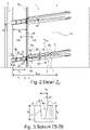
Fig. 2 eine vergrößerte Draufsicht auf das Detail Z2 derFig. 1 , -
Fig. 3 einen Schnitt entlang der Linie III-III derFig. 2 , -
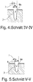
Fig. 4 einen Schnitt entlang der Linie IV-IV derFig. 2 , -
Fig. 5 einen Schnitt entlang der Linie V-V derFig. 2 , -
Fig. 6 einen Schnitt entlang der Linie VI-VI derFig. 2 und -
Fig. 7 einen Schnitt entlang der Linie VII-VII derFig. 2 . - Gemäß der Erfindung ausgeführte Fahrzeugluftreifen sind Reifen für mehrspurige Kraftfahrzeuge, sowie vorzugsweise Reifen in Radialbauart für Personenkraftwagen, Vans oder Light-Trucks (=Leichte LKWs mit zGM ≤ 7,5 t).
-
Fig. 1 zeigt eine Draufsicht auf einen Umfangsabschnitt eines Laufstreifens eines Fahrzeugluftreifens. Die seitlichen Ränder der Bodenaufstandsfläche des Laufstreifens sind durch gestrichelte Linien 1 angedeutet. Die Bodenaufstandsfläche entspricht dem statisch ermittelten Footprint gemäß E.T.R.T.O.-Standards (Last bei 70 % der maximalen Tragfähigkeit bei einem Innendruck von 85 % nach E.T.R.T.O.-Norm). - Der Laufstreifen weist zwei schulterseitige Profilblockreihen 1 und zwei mittlere Profilrippen 2 auf, wobei die mittleren Profilrippen 2 durch eine zentrale Umfangsrille 3 und die schulterseitigen Profilblockreihen 1 zur jeweils benachbarten mittleren Profilrippe 2 durch je eine schulterseitige Umfangsrille 4 getrennt sind. Die Umfangsrillen 3, 4 verlaufen beim gezeigten Ausführungsbeispiel in Draufsicht gerade und sind in radialer Richtung auf die jeweils vorgesehene Profiltiefe Tp (
Fig. 6 , gezeigt für eine schulterseitige Umfangsrille 4) ausgeführt, welche für den bevorzugten Reifentyp üblicherweise 6,5 mm bis 10,0 mm beträgt. Die mittleren Profilrippen 2 sind lediglich schematisch dargestellt und können in an sich bekannter Weise mit Rillen, Einschnitten und dergleichen strukturiert sein. - Die schulterseitigen Profilblockreihen 1 weisen jeweils eine Vielzahl von schulterseitigen Profilblöcken 1a auf, welche voneinander durch in die jeweilige schulterseitige Umfangsrille 4 einmündende, schulterseitige Querrillen 5 getrennt sind. Die schulterseitigen Querrillen 5 verlaufen, in Draufsicht betrachtet, gerade, innerhalb jeder schulterseitigen Profilblockreihe 1 parallel zueinander sowie zur axialen Richtung unter einem Winkel α (
Fig. 2 ) von 0° bis 25°, insbesondere von 5° bis 15°, wobei beim gezeigten Ausführungsbeispiel die in der einen schulterseitigen Profilblockreihe 1 befindlichen schulterseitigen Querrillen 5 zu den in der anderen schulterseitigen Profilblockreihe 1 befindlichen schulterseitigen Querrillen 5 bezüglich der axialen Richtung gegensinnig geneigt sind. - Die weitere Ausgestaltung der schulterseitigen Profilblockreihen 1 und der schulterseitigen Querrillen 5 wird nachfolgend anhand der in
Fig. 1 rechten schulterseitigen Profilblockreihe 1 sowie unter Bezugnahme aufFig. 2 bis Fig. 7 erläutert. InFig. 2 ist bei der unteren Querrille 5 innerhalb der Bodenaufstandsfläche die zugehörige Rillenmittellinie mQR eingezeichnet. - Gemäß
Fig. 2 weist jede schulterseitige Querrille 5 innerhalb der Bodenaufstandsfläche eine an der Laufstreifenperipherie ermittelte, in die axialer Richtung projizierte Länge lQR auf und setzt sich aus einem über den seitlichen Rand (Linie 1) der Bodenaufstandsfläche hinausverlaufenden, laufstreifenaußenseitigen Rillenabschnitt 5a, einen gegenüber diesen schmäler ausgeführten laufstreifeninnenseitigen Rillenabschnitt 5b und einem optionalen Übergangsabschnitt 5c zusammen. Die Querrille 5 ist über sämtliche Abschnitte 5a, 5b, 5c durch einen Rillengrund 6 und zwei Rillenflanken 7 begrenzt. - Der laufstreifenaußenseitige Rillenabschnitt 5a verläuft über einen Großteil der Länge lQR der Querrille 5 und weist, jeweils ermittelt innerhalb der Bodenaufstandsfläche, eine an der Laufstreifenperipherie senkrecht zur Rillenmittellinie mQR gemessene Breite ba (vergl.
Fig. 3 ) von 2,5 mm bis 5,5 mm, insbesondere von 3,0 mm bis 4,5 mm, und in radialer Richtung an seiner tiefsten Stelle eine Tiefe ta (Fig. 3 ) von bis zu 100% der Profiltiefe Tp (Fig. 3 ) auf, wobei die Tiefe ta insbesondere 1,0 mm bis 1,5 mm geringer ist als die Profiltiefe Tp. GemäßFig. 3 verlaufen die Rillenflanken 7 im laufstreifenaußenseitigen Rillenabschnitt 5a, im senkrecht zur Rillenmittellinie mQR ausgerichteten Querschnitt betrachtet (vergl. Schnittlinie III-III inFig. 2 ), zur radialen Richtung jeweils unter einem konstanten Winkel β von 0° bis 12°, insbesondere von zumindest 3°, wobei der Winkel β der einen Rillenflanke 7 vom Winkel β der anderen Rillenflanke 7 um insbesondere bis zu 7° abweichen kann. - Wie
Fig. 2 ferner zeigt, weist der laufstreifeninnenseitige Rillenabschnitt 5b eine in die axiale Richtung projizierte, an der Laufstreifenperipherie ermittelte, auf die Rillenmittellinie mQR bezogene Länge lb von 30% bis 40%, insbesondere von 33% bis 37%, der Länge lQR der Querrille 5 sowie eine an der Laufstreifenperipherie senkrecht zur Rillenmittellinie mQR gemessene Breite bb (vergl.Fig. 4, Fig. 5 ) von 50% bis 70%, insbesondere von 55% bis 65%, der Breite ba des laufstreifenaußenseitigen Rillenabschnittes 5a auf. Die Rillenflanken 7 verlaufen im laufstreifeninnenseitigen Rillenabschnitt 5b, im senkrecht zur Rillenmittellinie mQR ausgerichteten Querschnitt betrachtet, zur radialen Richtung jeweils unter einem konstanten Winkel γ (Fig. 4 und Fig. 5 ) von 0° bis 10°, insbesondere von 3° bis 7°, wobei die Winkel γ der beiden Rillenflanken 7 vorzugsweise übereinstimmen. - Der Übergangsabschnitt 5c weist eine an der Laufstreifenperipherie ermittelte, in die axiale Richtung projizierte, auf die Mittellinie mQR bezogene Länge lc von 1,0 mm bis 3,0 mm auf, verbreitert sich trichterförmig vom laufstreifeninnenseitigen Rillenabschnitt 5b zum laufstreifenaußenseitigen Rillenabschnitt 5a, wobei er an der Anschlussstelle zum laufstreifeninnenseitigen Rillenabschnitt 5b dessen Breite bb und an der Anschlussstelle zum laufstreifenaußenseitigen Rillenabschnitt 5a dessen Breite ba aufweist. Die Rillenflanken 7 verlaufen im Übergangsabschnitt 5c vorzugsweise übereinstimmend zu einem der Rillenabschnitte 5a, 5b und können alternativ in radialer Richtung verlaufen.
- Wie
Fig. 6 zeigt, weist der Rillengrund 6 einen sich über den kompletten laufstreifeninnenseitigen Rillenabschnitt 5b erstreckenden, beim gezeigten Ausführungsbeispiel in den Übergangsabschnitt 5c hineinragenden, mehrfach gestuften Grundabschnitt 6b auf, durch welchen der laufstreifeninnenseitige Rillenabschnitt 5b über seine gesamte Erstreckung seichter ausgeführt ist als der laufstreifenaußenseitige Rillenabschnitt 5a innerhalb der Bodenaufstandsfläche. Der gestuften Grundabschnitt 6b umfasst eine am weitesten von der schulterseitigen Umfangsrille 4 entfernte erste Stufenfläche 6bi, eine mittlere zweite Stufenflächen 6b2 und eine zur schulterseitigen Umfangsrille 4 verlaufende dritte Stufenfläche 6b3, wobei sich die Stufenflächen 6b1, 6b2, 6b3 gegenüber dem Niveau der Profiltiefe Tp in unterschiedlichen, in radialer Richtung ermittelten, jeweils konstanten Abständen ab1 (Stufenfläche 6b1), ab2 (Stufenfläche 6b2), ab3 (Stufenflächen 6b3) befinden. Die Abstände ab1, ab2, ab3 nehmen von Stufenfläche zu Stufenfläche in Richtung zur schulterseitigen Umfangsrille 4 schrittweise zu, wobei der kleinste Abstand ab1 mindestens 2,0 mm und der größte Abstand ab3 höchstens 50%, insbesondere höchstens 40%, der Profiltiefe Tp beträgt. Gemäß einer bevorzugten Ausführung beträgt der Abstand ab1 2,0 mm bis 3,0 mm, bevorzugt 2,5 mm, wobei der Abstand ab2 um 0,5 mm bis 1,5 mm, bevorzugt um 1,0 mm, größer ist als der Abstand ab1 und wobei der Abstand ab3 um 0,5 mm bis 1,5 mm, bevorzugt um 1,0 mm, größer ist als der Abstand ab2. Beim gezeigten Ausführungsbeispiel ragt die erste Stufenfläche 6b1 mit einem Endabschnitt in den Übergangsabschnitt 5c hinein. - Gemäß
Fig. 2 ist beim gezeigten Ausführungsbeispiel in der schulterseitigen Profilblockreihe 1 eine sämtliche schulterseitige Profilblöcke 1a durchquerende, in Draufsicht gerade sowie in Umfangsrichtung umlaufende Zusatznut 8 ausgebildet, welche durch die Querrillen 5 partiell unterbrochen ist, in diese daher einmündet und - bezogen auf ihre Nutmittellinie mz - zur schulterseitigen Umfangsrille 4 an der Laufstreifenperipherie in axialer Richtung einen Abstand az von 30% bis 40% der Länge lQR der Querrillen 5 aufweist. WieFig. 7 zeigt, weist die Zusatznut 8 einen flach U-förmigen Querschnitt, an der Laufstreifenperipherie eine in axialer Richtung ermittelte Breite bz von 1,0 mm bis 3,0 mm und in radialer Richtung eine Tiefe tz von 1,5 mm bis 2,5 mm, insbesondere von 2,0 mm, auf. Der Abstand az und die Breite bz sind, wie inFig. 2 gezeigt, vorzugsweise derart auf die Länge lb des laufstreifeninnenseitigen Rillenabschnittes 5b und die Länge lc des Übergangsabschnittes 5c abgestimmt, dass die Zusatznut 8 ausschließlich in die Übergangsabschnitte 5c der Querrillen 5 einmündet. Alternativ kann die Zusatznut 8 in die laufstreifenaußenseitigen Rillenabschnitte 5a der Querrillen 5 oder die laufstreifeninnenseitigen Rillenabschnitte 5b der Querrillen 5 einmünden. Sind Querrillen 5 ohne Übergangsabschnitte 5c vorgesehen, mündet die Zusatznut 8 vorzugsweise am gegenseitigen Anschlussbereich der Rillenabschnitte 5a, 5b, also gleichzeitig in beide Rillenabschnitte 5a, 5b, oder angrenzend am gegenseitigen Anschlussbereich der Rillenabschnitte 5a, 5b in einen der Rillenabschnitte 5a, 5b ein. - Die Erfindung ist auf das beschriebene Ausführungsbeispiel nicht beschränkt.
- Der Laufstreifen weist zumindest eine gemäß der Erfindung ausgeführte schulterseitige Profilblockreihe 1 auf. Die Zusatzunten 8 sowie die Übergangsabschnitte 5c sind optional. Der gestufte Grundabschnitt 6b weist zumindest zwei Stufenflächen auf und kann insbesondere bis zu vier Stufenflächen aufweisen.
-
- 1
- schulterseitige Profilblockreihe
- 1a
- schulterseitiger Profilblock
- 2
- mittlere Profilrippe
- 3
- zentrale Umfangsrille
- 4
- schulterseitige Umfangsrille
- 5
- schulterseitige Querrille
- 5a
- laufstreifenaußenseitiger Rillenabschnitt
- 5b
- laufstreifeninnenseitiger Rillenabschnitt
- 5c
- Übergangsabschnitt
- 6
- Rillengrund
- 6b
- Grundabschnitt
- 6b1, 6b2, 6b3
- Stufenfläche
- 7
- Rillenflanke
- 8
- Zusatznut
- ab1, ab2, ab3, az
- Abstand
- ba, bb, bz
- Breite
- l
- Linie (seitlicher Rand der Bodenaufstandsfläche)
- lQR, la, lb, lc
- Länge
- mQR
- Rillenmittellinie
- mz
- Nutmittellinie
- ta, tz
- Tiefe
- TP
- Profiltiefe
- Z2
- Detail
- α, β, γ
- Winkel
Claims (15)
- Fahrzeugluftreifen mit einem Laufstreifen mit zumindest einer schulterseitigen Profilblockreihe (1), welche durch eine auf Profiltiefe (Tp) ausgeführte, schulterseitige Umfangsrille (4) begrenzt und mit in Draufsicht parallel zueinander verlaufenden Querrillen (5) mit jeweils einem Rillengrund (6) und einer innerhalb der Bodenaufstandsfläche in die axiale Richtung projizierten Länge (lQR) versehen ist, wobei jede Querrille (5) einen über den Großteil ihrer Länge (lQR) sowie über den seitlichen Rand (l) der Bodenaufstandsfläche verlaufenden laufstreifenaußenseitigen Rillenabschnitt (5a) mit einer innerhalb der Bodenaufstandsfläche ermittelten Breite (ba) und einen in die schulterseitige Umfangsrille (4) einmündenden, laufstreifeninnenseitigen Rillenabschnitt (5b) mit einer gegenüber der Breite (ba) des laufstreifenaußenseitigen Rillenabschnittes (5a) geringeren Breite (bb) aufweist, wobei der laufstreifeninnenseitige Rillenabschnitt (5b) über seine gesamte Erstreckung in radialer Richtung seichter ausgeführt ist als der laufstreifenaußenseitige Rillenabschnitt (5a),
dadurch gekennzeichnet,
dass der Rillengrund (6) einen über den laufstreifeninnenseitigen Rillenabschnitt (5b) verlaufenden, gestuften Grundabschnitt (6b) mit zumindest zwei Stufenflächen (6b1, 6b2, 6b3) aufweist, wobei die Stufenflächen (6b1, 6b2, 6b3) zum Niveau der Profiltiefe (Tp) in radialer Richtung ermittelte konstante Abstände (ab1, ab2, ab3) aufweisen, welche von Stufenfläche (6b1, 6b2, 6b3) zu Stufenfläche (6b1, 6b2, 6b3) in Richtung zur schulterseitigen Umfangsrille (4) schrittweise zunehmen. - Fahrzeugluftreifen nach Anspruch 1, dadurch gekennzeichnet, dass jener Abstand (ab3), welcher am größten ist, höchstens 50%, insbesondere höchstens 40%, der Profiltiefe (Tp) beträgt.
- Fahrzeugluftreifen nach Anspruch 1 oder 2, dadurch gekennzeichnet, dass jener Abstand (ab1), welcher am kleinsten ist, mindestens 2,0 mm beträgt.
- Fahrzeugluftreifen nach einem der Ansprüche 1 bis 3, dadurch gekennzeichnet, dass sich die Abstände (ab1, ab2, ab3) unmittelbar benachbarter Stufenflächen (6b1, 6b2, 6b3) voneinander um 0,5 mm bis 1,5 mm, insbesondere um 1,0 mm, unterscheiden.
- Fahrzeugluftreifen nach einem der Ansprüche 1 bis 4, dadurch gekennzeichnet, dass der gestufte Grundabschnitt (6b) zumindest drei, insbesondere genau drei oder genau vier, Stufenflächen (6b1, 6b2, 6b3) aufweist.
- Fahrzeugluftreifen nach Anspruch 5, dadurch gekennzeichnet, dass der gestufte Grundabschnitt (6b) genau drei Stufenflächen (6b1, 6b2, 6b3) aufweist, wobei- der Abstand (ab1) der ersten Stufenfläche (6b1) zum Niveau der Profiltiefe (Tp) 2,0 mm bis 3,0 mm, insbesondere 2,5 mm, beträgt,- der Abstand (ab2) der zweiten Stufenfläche (6b2) zum Niveau der Profiltiefe (Tp) um 0,5 mm bis 1,5 mm, bevorzugt um 1,0 mm, größer ist als der Abstand (ab1) der ersten Stufenfläche (6b1) zum Niveau der Profiltiefe (TP) und- der Abstand (ab3) der dritten Stufenfläche (6b3) zum Niveau der Profiltiefe (Tp) um 0,5 mm bis 1,5 mm, bevorzugt um 1,0 mm, größer ist als der Abstand (ab2) der zweiten Stufenfläche (6b2) zum Niveau der Profiltiefe (TP).
- Fahrzeugluftreifen nach einem der Ansprüche 1 bis 6, dadurch gekennzeichnet, dass der laufstreifeninnenseitige Rillenabschnitt (5b) eine in die axiale Richtung projizierte Länge (lb) von 30% bis 40%, insbesondere von 33% bis 37%, der Länge (lQR) der Querrille (5) aufweist.
- Fahrzeugluftreifen nach einem der Ansprüche 1 bis 7, dadurch gekennzeichnet, dass die Breite (bb) des laufstreifeninnenseitigen Rillenabschnittes (5b) 50% bis 70%, insbesondere 55% bis 65%, der Breite (ba) des laufstreifenaußenseitigen Rillenabschnittes (5a) beträgt.
- Fahrzeugluftreifen nach einem der Ansprüche 1 bis 8, dadurch gekennzeichnet, dass die Breite (ba) des laufstreifenaußenseitigen Rillenabschnittes (5a) 2,5 mm bis 5,5 mm, insbesondere von 3,0 mm bis 4,5 mm, beträgt.
- Fahrzeugluftreifen nach einem der Ansprüche 1 bis 9, dadurch gekennzeichnet, dass der laufstreifenaußenseitige Rillenabschnitt (5a) in radialer Richtung an seiner tiefsten Stelle eine Tiefe (ta) von bis zu 100% der Profiltiefe (Tp) aufweist, wobei die Tiefe (ta) insbesondere um 1,0 mm bis 1,5 mm geringer ist als die Profiltiefe (TP).
- Fahrzeugluftreifen nach einem der Ansprüche 1 bis 10, dadurch gekennzeichnet, dass sich die Querrille (5) aus dem laufstreifeninnenseitigen Rillenabschnitt (5b), dem laufstreifenaußenseitigen Rillenabschnitt (5a) und einem zwischen den Rillenabschnitten (5a, 5b) ausgebildeten, sich trichterförmig zwischen diesen verbreiternden Übergangsabschnitt (5c) zusammensetzt, welcher eine in die axiale Richtung projizierte Länge (lc) von 1,0 mm bis 3,0 mm aufweist.
- Fahrzeugluftreifen nach einem der Ansprüche 1 bis 11, dadurch gekennzeichnet, dass in der schulterseitigen Profilblockreihe (1) eine durch die Querrillen (5) unterbrochene, in Draufsicht gerade sowie in Umfangsrichtung umlaufende Zusatznut (8) ausgebildet ist, welche eine Breite (bz) von 1,0 mm bis 3,0 mm, in radialer Richtung eine Tiefe (tz) von 1,5 mm bis 2,5 mm, insbesondere von 2,0 mm, und - bezogen auf ihre Nutmittellinie (mz) - zur schulterseitigen Umfangsrille (4) in axialer Richtung einen Abstand (az) von 30% bis 40% der Länge (lQR) der Querrillen (5) aufweist.
- Fahrzeugluftreifen nach Anspruch 12, dadurch gekennzeichnet, dass die Zusatznut (8)a) am gegenseitigen Anschlussbereich der beiden Rillenabschnitte (5a, 5b) der Querrillen (5) oderb) angrenzend am gegenseitigen Anschlussbereich der beiden Rillenabschnitte (5a, 5b) der Querrillen (5) in einen der Rillenabschnitte (5a, 5b) oderc) in die gegebenenfalls vorgesehenen Übergangsabschnitte (5c) der jeweiligen Querrillen (5)
einmündet. - Fahrzeugluftreifen nach einem der Ansprüche 1 bis 13, dadurch gekennzeichnet, dass die Querrillen (5), in Draufsicht betrachtet, zur axialen Richtung unter einem Winkel (α) von 0° bis 25°, insbesondere von 5° bis 15°, verlaufen.
- Fahrzeugluftreifen nach einem der der Ansprüche 1 bis 14, dadurch gekennzeichnet, dass der Laufstreifen eine zweite schulterseitige Profilblockreihe (1) aufweist, welche bezüglich der Reifenäquatorialebene symmetrisch zur anderen schulterseitigen Profilblockreihe (1) ausgeführt ist, wobei die zweite schulterseitige Profilblockreihe (1) gegebenenfalls gegenüber der anderen schulterseitigen Profilblockreihe (1) in Umfangsrichtung versetzt ist.
Applications Claiming Priority (1)
| Application Number | Priority Date | Filing Date | Title |
|---|---|---|---|
| DE102020216408.8A DE102020216408A1 (de) | 2020-12-21 | 2020-12-21 | Fahrzeugluftreifen |
Publications (2)
| Publication Number | Publication Date |
|---|---|
| EP4015247A1 true EP4015247A1 (de) | 2022-06-22 |
| EP4015247B1 EP4015247B1 (de) | 2024-01-31 |
Family
ID=78789635
Family Applications (1)
| Application Number | Title | Priority Date | Filing Date |
|---|---|---|---|
| EP21210070.5A Active EP4015247B1 (de) | 2020-12-21 | 2021-11-23 | Fahrzeugluftreifen |
Country Status (2)
| Country | Link |
|---|---|
| EP (1) | EP4015247B1 (de) |
| DE (1) | DE102020216408A1 (de) |
Citations (7)
| Publication number | Priority date | Publication date | Assignee | Title |
|---|---|---|---|---|
| KR950011150A (ko) * | 1993-10-26 | 1995-05-15 | 홍건희 | 공기압타이어 |
| JPH11198612A (ja) * | 1998-01-13 | 1999-07-27 | Sumitomo Rubber Ind Ltd | 空気入りタイヤ |
| US20060102267A1 (en) * | 2004-11-18 | 2006-05-18 | Sumitomo Rubber Industries, Ltd. | Heavy duty pneumatic tire |
| DE102007015354A1 (de) * | 2007-03-30 | 2008-10-02 | Continental Aktiengesellschaft | Fahrzeugluftreifen |
| US20110041972A1 (en) * | 2009-08-24 | 2011-02-24 | Naoki Kageyama | Pneumatic tire |
| EP3124290A1 (de) | 2015-07-30 | 2017-02-01 | Continental Reifen Deutschland GmbH | Fahrzeugluftreifen |
| US20200086691A1 (en) * | 2018-09-13 | 2020-03-19 | Hankook Tire & Technology Co., Ltd. | Pneumatic tire |
-
2020
- 2020-12-21 DE DE102020216408.8A patent/DE102020216408A1/de active Pending
-
2021
- 2021-11-23 EP EP21210070.5A patent/EP4015247B1/de active Active
Patent Citations (7)
| Publication number | Priority date | Publication date | Assignee | Title |
|---|---|---|---|---|
| KR950011150A (ko) * | 1993-10-26 | 1995-05-15 | 홍건희 | 공기압타이어 |
| JPH11198612A (ja) * | 1998-01-13 | 1999-07-27 | Sumitomo Rubber Ind Ltd | 空気入りタイヤ |
| US20060102267A1 (en) * | 2004-11-18 | 2006-05-18 | Sumitomo Rubber Industries, Ltd. | Heavy duty pneumatic tire |
| DE102007015354A1 (de) * | 2007-03-30 | 2008-10-02 | Continental Aktiengesellschaft | Fahrzeugluftreifen |
| US20110041972A1 (en) * | 2009-08-24 | 2011-02-24 | Naoki Kageyama | Pneumatic tire |
| EP3124290A1 (de) | 2015-07-30 | 2017-02-01 | Continental Reifen Deutschland GmbH | Fahrzeugluftreifen |
| US20200086691A1 (en) * | 2018-09-13 | 2020-03-19 | Hankook Tire & Technology Co., Ltd. | Pneumatic tire |
Also Published As
| Publication number | Publication date |
|---|---|
| DE102020216408A1 (de) | 2022-06-23 |
| EP4015247B1 (de) | 2024-01-31 |
Similar Documents
| Publication | Publication Date | Title |
|---|---|---|
| DE112017002199B4 (de) | Luftreifen | |
| EP3643527B1 (de) | Fahrzeugluftreifen | |
| EP3300926B1 (de) | Fahrzeugluftreifen | |
| EP3388256A1 (de) | Fahrzeugluftreifen | |
| EP4244079B1 (de) | Fahrzeugluftreifen | |
| EP4058304B1 (de) | Fahrzeugluftreifen | |
| DE102004024162A1 (de) | Luftreifen | |
| EP3750723B1 (de) | Fahrzeugluftreifen | |
| EP4015247B1 (de) | Fahrzeugluftreifen | |
| EP4173847B1 (de) | Fahrzeugluftreifen | |
| EP3300925B1 (de) | Fahrzeugluftreifen | |
| EP0618092B1 (de) | Fahrzeugreifen | |
| EP3888951B1 (de) | Fahrzeugluftreifen | |
| EP4281296B1 (de) | Fahrzeugluftreifen | |
| DE102021211351A1 (de) | Fahrzeugluftreifen | |
| DE102021210022A1 (de) | Fahrzeugluftreifen | |
| EP4281297B1 (de) | Fahrzeugluftreifen | |
| EP4003760A1 (de) | Fahrzeugluftreifen | |
| DE102019206679A1 (de) | Fahrzeugluftreifen | |
| EP4301609B1 (de) | Fahrzeugluftreifen | |
| DE102024206574A1 (de) | Fahrzeugreifen | |
| DE102024108084A1 (de) | Fahrzeugreifen | |
| DE102024205988A1 (de) | Fahrzeugreifen | |
| EP4667240A1 (de) | Fahrzeugreifen | |
| EP4514632A1 (de) | Fahrzeugreifen |
Legal Events
| Date | Code | Title | Description |
|---|---|---|---|
| PUAI | Public reference made under article 153(3) epc to a published international application that has entered the european phase |
Free format text: ORIGINAL CODE: 0009012 |
|
| STAA | Information on the status of an ep patent application or granted ep patent |
Free format text: STATUS: THE APPLICATION HAS BEEN PUBLISHED |
|
| AK | Designated contracting states |
Kind code of ref document: A1 Designated state(s): AL AT BE BG CH CY CZ DE DK EE ES FI FR GB GR HR HU IE IS IT LI LT LU LV MC MK MT NL NO PL PT RO RS SE SI SK SM TR |
|
| STAA | Information on the status of an ep patent application or granted ep patent |
Free format text: STATUS: REQUEST FOR EXAMINATION WAS MADE |
|
| 17P | Request for examination filed |
Effective date: 20221222 |
|
| RBV | Designated contracting states (corrected) |
Designated state(s): AL AT BE BG CH CY CZ DE DK EE ES FI FR GB GR HR HU IE IS IT LI LT LU LV MC MK MT NL NO PL PT RO RS SE SI SK SM TR |
|
| GRAP | Despatch of communication of intention to grant a patent |
Free format text: ORIGINAL CODE: EPIDOSNIGR1 |
|
| STAA | Information on the status of an ep patent application or granted ep patent |
Free format text: STATUS: GRANT OF PATENT IS INTENDED |
|
| INTG | Intention to grant announced |
Effective date: 20230912 |
|
| GRAS | Grant fee paid |
Free format text: ORIGINAL CODE: EPIDOSNIGR3 |
|
| GRAA | (expected) grant |
Free format text: ORIGINAL CODE: 0009210 |
|
| STAA | Information on the status of an ep patent application or granted ep patent |
Free format text: STATUS: THE PATENT HAS BEEN GRANTED |
|
| P01 | Opt-out of the competence of the unified patent court (upc) registered |
Effective date: 20231207 |
|
| AK | Designated contracting states |
Kind code of ref document: B1 Designated state(s): AL AT BE BG CH CY CZ DE DK EE ES FI FR GB GR HR HU IE IS IT LI LT LU LV MC MK MT NL NO PL PT RO RS SE SI SK SM TR |
|
| REG | Reference to a national code |
Ref country code: GB Ref legal event code: FG4D Free format text: NOT ENGLISH Ref country code: CH Ref legal event code: EP |
|
| REG | Reference to a national code |
Ref country code: DE Ref legal event code: R096 Ref document number: 502021002566 Country of ref document: DE |
|
| REG | Reference to a national code |
Ref country code: IE Ref legal event code: FG4D Free format text: LANGUAGE OF EP DOCUMENT: GERMAN |
|
| RAP4 | Party data changed (patent owner data changed or rights of a patent transferred) |
Owner name: CONTINENTAL REIFEN DEUTSCHLAND GMBH |
|
| REG | Reference to a national code |
Ref country code: DE Ref legal event code: R081 Ref document number: 502021002566 Country of ref document: DE Owner name: CONTINENTAL REIFEN DEUTSCHLAND GMBH, DE Free format text: FORMER OWNER: CONTINENTAL REIFEN DEUTSCHLAND GMBH, 30173 HANNOVER, DE |
|
| REG | Reference to a national code |
Ref country code: SE Ref legal event code: TRGR |
|
| REG | Reference to a national code |
Ref country code: LT Ref legal event code: MG9D |
|
| REG | Reference to a national code |
Ref country code: NL Ref legal event code: FP |
|
| PG25 | Lapsed in a contracting state [announced via postgrant information from national office to epo] |
Ref country code: IS Free format text: LAPSE BECAUSE OF FAILURE TO SUBMIT A TRANSLATION OF THE DESCRIPTION OR TO PAY THE FEE WITHIN THE PRESCRIBED TIME-LIMIT Effective date: 20240531 |
|
| PG25 | Lapsed in a contracting state [announced via postgrant information from national office to epo] |
Ref country code: LT Free format text: LAPSE BECAUSE OF FAILURE TO SUBMIT A TRANSLATION OF THE DESCRIPTION OR TO PAY THE FEE WITHIN THE PRESCRIBED TIME-LIMIT Effective date: 20240131 |
|
| PG25 | Lapsed in a contracting state [announced via postgrant information from national office to epo] |
Ref country code: GR Free format text: LAPSE BECAUSE OF FAILURE TO SUBMIT A TRANSLATION OF THE DESCRIPTION OR TO PAY THE FEE WITHIN THE PRESCRIBED TIME-LIMIT Effective date: 20240501 |
|
| PG25 | Lapsed in a contracting state [announced via postgrant information from national office to epo] |
Ref country code: RS Free format text: LAPSE BECAUSE OF FAILURE TO SUBMIT A TRANSLATION OF THE DESCRIPTION OR TO PAY THE FEE WITHIN THE PRESCRIBED TIME-LIMIT Effective date: 20240430 Ref country code: HR Free format text: LAPSE BECAUSE OF FAILURE TO SUBMIT A TRANSLATION OF THE DESCRIPTION OR TO PAY THE FEE WITHIN THE PRESCRIBED TIME-LIMIT Effective date: 20240131 |
|
| PG25 | Lapsed in a contracting state [announced via postgrant information from national office to epo] |
Ref country code: ES Free format text: LAPSE BECAUSE OF FAILURE TO SUBMIT A TRANSLATION OF THE DESCRIPTION OR TO PAY THE FEE WITHIN THE PRESCRIBED TIME-LIMIT Effective date: 20240131 |
|
| PG25 | Lapsed in a contracting state [announced via postgrant information from national office to epo] |
Ref country code: RS Free format text: LAPSE BECAUSE OF FAILURE TO SUBMIT A TRANSLATION OF THE DESCRIPTION OR TO PAY THE FEE WITHIN THE PRESCRIBED TIME-LIMIT Effective date: 20240430 Ref country code: NO Free format text: LAPSE BECAUSE OF FAILURE TO SUBMIT A TRANSLATION OF THE DESCRIPTION OR TO PAY THE FEE WITHIN THE PRESCRIBED TIME-LIMIT Effective date: 20240430 Ref country code: LT Free format text: LAPSE BECAUSE OF FAILURE TO SUBMIT A TRANSLATION OF THE DESCRIPTION OR TO PAY THE FEE WITHIN THE PRESCRIBED TIME-LIMIT Effective date: 20240131 Ref country code: IS Free format text: LAPSE BECAUSE OF FAILURE TO SUBMIT A TRANSLATION OF THE DESCRIPTION OR TO PAY THE FEE WITHIN THE PRESCRIBED TIME-LIMIT Effective date: 20240531 Ref country code: HR Free format text: LAPSE BECAUSE OF FAILURE TO SUBMIT A TRANSLATION OF THE DESCRIPTION OR TO PAY THE FEE WITHIN THE PRESCRIBED TIME-LIMIT Effective date: 20240131 Ref country code: GR Free format text: LAPSE BECAUSE OF FAILURE TO SUBMIT A TRANSLATION OF THE DESCRIPTION OR TO PAY THE FEE WITHIN THE PRESCRIBED TIME-LIMIT Effective date: 20240501 Ref country code: FI Free format text: LAPSE BECAUSE OF FAILURE TO SUBMIT A TRANSLATION OF THE DESCRIPTION OR TO PAY THE FEE WITHIN THE PRESCRIBED TIME-LIMIT Effective date: 20240131 Ref country code: ES Free format text: LAPSE BECAUSE OF FAILURE TO SUBMIT A TRANSLATION OF THE DESCRIPTION OR TO PAY THE FEE WITHIN THE PRESCRIBED TIME-LIMIT Effective date: 20240131 Ref country code: BG Free format text: LAPSE BECAUSE OF FAILURE TO SUBMIT A TRANSLATION OF THE DESCRIPTION OR TO PAY THE FEE WITHIN THE PRESCRIBED TIME-LIMIT Effective date: 20240131 |
|
| PG25 | Lapsed in a contracting state [announced via postgrant information from national office to epo] |
Ref country code: PL Free format text: LAPSE BECAUSE OF FAILURE TO SUBMIT A TRANSLATION OF THE DESCRIPTION OR TO PAY THE FEE WITHIN THE PRESCRIBED TIME-LIMIT Effective date: 20240131 Ref country code: PT Free format text: LAPSE BECAUSE OF FAILURE TO SUBMIT A TRANSLATION OF THE DESCRIPTION OR TO PAY THE FEE WITHIN THE PRESCRIBED TIME-LIMIT Effective date: 20240531 |
|
| PG25 | Lapsed in a contracting state [announced via postgrant information from national office to epo] |
Ref country code: PT Free format text: LAPSE BECAUSE OF FAILURE TO SUBMIT A TRANSLATION OF THE DESCRIPTION OR TO PAY THE FEE WITHIN THE PRESCRIBED TIME-LIMIT Effective date: 20240531 Ref country code: PL Free format text: LAPSE BECAUSE OF FAILURE TO SUBMIT A TRANSLATION OF THE DESCRIPTION OR TO PAY THE FEE WITHIN THE PRESCRIBED TIME-LIMIT Effective date: 20240131 Ref country code: LV Free format text: LAPSE BECAUSE OF FAILURE TO SUBMIT A TRANSLATION OF THE DESCRIPTION OR TO PAY THE FEE WITHIN THE PRESCRIBED TIME-LIMIT Effective date: 20240131 |
|
| PG25 | Lapsed in a contracting state [announced via postgrant information from national office to epo] |
Ref country code: DK Free format text: LAPSE BECAUSE OF FAILURE TO SUBMIT A TRANSLATION OF THE DESCRIPTION OR TO PAY THE FEE WITHIN THE PRESCRIBED TIME-LIMIT Effective date: 20240131 |
|
| PG25 | Lapsed in a contracting state [announced via postgrant information from national office to epo] |
Ref country code: SM Free format text: LAPSE BECAUSE OF FAILURE TO SUBMIT A TRANSLATION OF THE DESCRIPTION OR TO PAY THE FEE WITHIN THE PRESCRIBED TIME-LIMIT Effective date: 20240131 |
|
| PG25 | Lapsed in a contracting state [announced via postgrant information from national office to epo] |
Ref country code: CZ Free format text: LAPSE BECAUSE OF FAILURE TO SUBMIT A TRANSLATION OF THE DESCRIPTION OR TO PAY THE FEE WITHIN THE PRESCRIBED TIME-LIMIT Effective date: 20240131 Ref country code: EE Free format text: LAPSE BECAUSE OF FAILURE TO SUBMIT A TRANSLATION OF THE DESCRIPTION OR TO PAY THE FEE WITHIN THE PRESCRIBED TIME-LIMIT Effective date: 20240131 |
|
| PG25 | Lapsed in a contracting state [announced via postgrant information from national office to epo] |
Ref country code: SK Free format text: LAPSE BECAUSE OF FAILURE TO SUBMIT A TRANSLATION OF THE DESCRIPTION OR TO PAY THE FEE WITHIN THE PRESCRIBED TIME-LIMIT Effective date: 20240131 |
|
| PG25 | Lapsed in a contracting state [announced via postgrant information from national office to epo] |
Ref country code: SM Free format text: LAPSE BECAUSE OF FAILURE TO SUBMIT A TRANSLATION OF THE DESCRIPTION OR TO PAY THE FEE WITHIN THE PRESCRIBED TIME-LIMIT Effective date: 20240131 Ref country code: SK Free format text: LAPSE BECAUSE OF FAILURE TO SUBMIT A TRANSLATION OF THE DESCRIPTION OR TO PAY THE FEE WITHIN THE PRESCRIBED TIME-LIMIT Effective date: 20240131 Ref country code: RO Free format text: LAPSE BECAUSE OF FAILURE TO SUBMIT A TRANSLATION OF THE DESCRIPTION OR TO PAY THE FEE WITHIN THE PRESCRIBED TIME-LIMIT Effective date: 20240131 Ref country code: EE Free format text: LAPSE BECAUSE OF FAILURE TO SUBMIT A TRANSLATION OF THE DESCRIPTION OR TO PAY THE FEE WITHIN THE PRESCRIBED TIME-LIMIT Effective date: 20240131 Ref country code: DK Free format text: LAPSE BECAUSE OF FAILURE TO SUBMIT A TRANSLATION OF THE DESCRIPTION OR TO PAY THE FEE WITHIN THE PRESCRIBED TIME-LIMIT Effective date: 20240131 Ref country code: CZ Free format text: LAPSE BECAUSE OF FAILURE TO SUBMIT A TRANSLATION OF THE DESCRIPTION OR TO PAY THE FEE WITHIN THE PRESCRIBED TIME-LIMIT Effective date: 20240131 |
|
| REG | Reference to a national code |
Ref country code: DE Ref legal event code: R097 Ref document number: 502021002566 Country of ref document: DE |
|
| PG25 | Lapsed in a contracting state [announced via postgrant information from national office to epo] |
Ref country code: IT Free format text: LAPSE BECAUSE OF FAILURE TO SUBMIT A TRANSLATION OF THE DESCRIPTION OR TO PAY THE FEE WITHIN THE PRESCRIBED TIME-LIMIT Effective date: 20240131 |
|
| PLBE | No opposition filed within time limit |
Free format text: ORIGINAL CODE: 0009261 |
|
| STAA | Information on the status of an ep patent application or granted ep patent |
Free format text: STATUS: NO OPPOSITION FILED WITHIN TIME LIMIT |
|
| PG25 | Lapsed in a contracting state [announced via postgrant information from national office to epo] |
Ref country code: IT Free format text: LAPSE BECAUSE OF FAILURE TO SUBMIT A TRANSLATION OF THE DESCRIPTION OR TO PAY THE FEE WITHIN THE PRESCRIBED TIME-LIMIT Effective date: 20240131 |
|
| 26N | No opposition filed |
Effective date: 20241101 |
|
| PG25 | Lapsed in a contracting state [announced via postgrant information from national office to epo] |
Ref country code: SI Free format text: LAPSE BECAUSE OF FAILURE TO SUBMIT A TRANSLATION OF THE DESCRIPTION OR TO PAY THE FEE WITHIN THE PRESCRIBED TIME-LIMIT Effective date: 20240131 |
|
| REG | Reference to a national code |
Ref country code: CH Ref legal event code: PL |
|
| PG25 | Lapsed in a contracting state [announced via postgrant information from national office to epo] |
Ref country code: MC Free format text: LAPSE BECAUSE OF FAILURE TO SUBMIT A TRANSLATION OF THE DESCRIPTION OR TO PAY THE FEE WITHIN THE PRESCRIBED TIME-LIMIT Effective date: 20240131 |
|
| PG25 | Lapsed in a contracting state [announced via postgrant information from national office to epo] |
Ref country code: LU Free format text: LAPSE BECAUSE OF NON-PAYMENT OF DUE FEES Effective date: 20241123 |
|
| REG | Reference to a national code |
Ref country code: CH Ref legal event code: PL |
|
| PG25 | Lapsed in a contracting state [announced via postgrant information from national office to epo] |
Ref country code: CH Free format text: LAPSE BECAUSE OF NON-PAYMENT OF DUE FEES Effective date: 20241130 |
|
| REG | Reference to a national code |
Ref country code: BE Ref legal event code: MM Effective date: 20241130 |
|
| PG25 | Lapsed in a contracting state [announced via postgrant information from national office to epo] |
Ref country code: BE Free format text: LAPSE BECAUSE OF NON-PAYMENT OF DUE FEES Effective date: 20241130 |
|
| PG25 | Lapsed in a contracting state [announced via postgrant information from national office to epo] |
Ref country code: FR Free format text: LAPSE BECAUSE OF NON-PAYMENT OF DUE FEES Effective date: 20241130 |
|
| PG25 | Lapsed in a contracting state [announced via postgrant information from national office to epo] |
Ref country code: IE Free format text: LAPSE BECAUSE OF NON-PAYMENT OF DUE FEES Effective date: 20241123 |
|
| PGFP | Annual fee paid to national office [announced via postgrant information from national office to epo] |
Ref country code: NL Payment date: 20251119 Year of fee payment: 5 |
|
| PGFP | Annual fee paid to national office [announced via postgrant information from national office to epo] |
Ref country code: DE Payment date: 20251130 Year of fee payment: 5 |
|
| PGFP | Annual fee paid to national office [announced via postgrant information from national office to epo] |
Ref country code: AT Payment date: 20260113 Year of fee payment: 5 |
|
| PGFP | Annual fee paid to national office [announced via postgrant information from national office to epo] |
Ref country code: SE Payment date: 20251119 Year of fee payment: 5 |
|
| PG25 | Lapsed in a contracting state [announced via postgrant information from national office to epo] |
Ref country code: HU Free format text: LAPSE BECAUSE OF FAILURE TO SUBMIT A TRANSLATION OF THE DESCRIPTION OR TO PAY THE FEE WITHIN THE PRESCRIBED TIME-LIMIT; INVALID AB INITIO Effective date: 20211123 |
|
| PG25 | Lapsed in a contracting state [announced via postgrant information from national office to epo] |
Ref country code: CY Free format text: LAPSE BECAUSE OF FAILURE TO SUBMIT A TRANSLATION OF THE DESCRIPTION OR TO PAY THE FEE WITHIN THE PRESCRIBED TIME-LIMIT; INVALID AB INITIO Effective date: 20211123 |