EP4015242A1 - Non-pneumatic tire and rim assembly - Google Patents
Non-pneumatic tire and rim assembly Download PDFInfo
- Publication number
- EP4015242A1 EP4015242A1 EP21212358.2A EP21212358A EP4015242A1 EP 4015242 A1 EP4015242 A1 EP 4015242A1 EP 21212358 A EP21212358 A EP 21212358A EP 4015242 A1 EP4015242 A1 EP 4015242A1
- Authority
- EP
- European Patent Office
- Prior art keywords
- pneumatic tire
- rim
- rim assembly
- previous
- bead
- Prior art date
- Legal status (The legal status is an assumption and is not a legal conclusion. Google has not performed a legal analysis and makes no representation as to the accuracy of the status listed.)
- Granted
Links
Images

Classifications
-
- B—PERFORMING OPERATIONS; TRANSPORTING
- B60—VEHICLES IN GENERAL
- B60C—VEHICLE TYRES; TYRE INFLATION; TYRE CHANGING; CONNECTING VALVES TO INFLATABLE ELASTIC BODIES IN GENERAL; DEVICES OR ARRANGEMENTS RELATED TO TYRES
- B60C7/00—Non-inflatable or solid tyres
- B60C7/10—Non-inflatable or solid tyres characterised by means for increasing resiliency
- B60C7/12—Non-inflatable or solid tyres characterised by means for increasing resiliency using enclosed chambers, e.g. gas-filled
- B60C7/125—Non-inflatable or solid tyres characterised by means for increasing resiliency using enclosed chambers, e.g. gas-filled enclosed chambers defined between rim and tread
-
- B—PERFORMING OPERATIONS; TRANSPORTING
- B60—VEHICLES IN GENERAL
- B60C—VEHICLE TYRES; TYRE INFLATION; TYRE CHANGING; CONNECTING VALVES TO INFLATABLE ELASTIC BODIES IN GENERAL; DEVICES OR ARRANGEMENTS RELATED TO TYRES
- B60C7/00—Non-inflatable or solid tyres
- B60C7/10—Non-inflatable or solid tyres characterised by means for increasing resiliency
- B60C7/102—Tyres built-up with separate rubber parts
-
- B—PERFORMING OPERATIONS; TRANSPORTING
- B60—VEHICLES IN GENERAL
- B60C—VEHICLE TYRES; TYRE INFLATION; TYRE CHANGING; CONNECTING VALVES TO INFLATABLE ELASTIC BODIES IN GENERAL; DEVICES OR ARRANGEMENTS RELATED TO TYRES
- B60C13/00—Tyre sidewalls; Protecting, decorating, marking, or the like, thereof
- B60C13/009—Tyre sidewalls; Protecting, decorating, marking, or the like, thereof comprising additional bead cores in the sidewall
-
- B—PERFORMING OPERATIONS; TRANSPORTING
- B60—VEHICLES IN GENERAL
- B60B—VEHICLE WHEELS; CASTORS; AXLES FOR WHEELS OR CASTORS; INCREASING WHEEL ADHESION
- B60B21/00—Rims
- B60B21/02—Rims characterised by transverse section
- B60B21/04—Rims characterised by transverse section with substantially radial flanges
-
- B—PERFORMING OPERATIONS; TRANSPORTING
- B60—VEHICLES IN GENERAL
- B60B—VEHICLE WHEELS; CASTORS; AXLES FOR WHEELS OR CASTORS; INCREASING WHEEL ADHESION
- B60B21/00—Rims
- B60B21/10—Rims characterised by the form of tyre-seat or flange, e.g. corrugated
- B60B21/102—Rims characterised by the form of tyre-seat or flange, e.g. corrugated the shape of bead seats
-
- B—PERFORMING OPERATIONS; TRANSPORTING
- B60—VEHICLES IN GENERAL
- B60C—VEHICLE TYRES; TYRE INFLATION; TYRE CHANGING; CONNECTING VALVES TO INFLATABLE ELASTIC BODIES IN GENERAL; DEVICES OR ARRANGEMENTS RELATED TO TYRES
- B60C15/00—Tyre beads, e.g. ply turn-up or overlap
- B60C15/04—Bead cores
-
- B—PERFORMING OPERATIONS; TRANSPORTING
- B60—VEHICLES IN GENERAL
- B60C—VEHICLE TYRES; TYRE INFLATION; TYRE CHANGING; CONNECTING VALVES TO INFLATABLE ELASTIC BODIES IN GENERAL; DEVICES OR ARRANGEMENTS RELATED TO TYRES
- B60C7/00—Non-inflatable or solid tyres
- B60C7/10—Non-inflatable or solid tyres characterised by means for increasing resiliency
- B60C7/14—Non-inflatable or solid tyres characterised by means for increasing resiliency using springs
-
- B—PERFORMING OPERATIONS; TRANSPORTING
- B60—VEHICLES IN GENERAL
- B60C—VEHICLE TYRES; TYRE INFLATION; TYRE CHANGING; CONNECTING VALVES TO INFLATABLE ELASTIC BODIES IN GENERAL; DEVICES OR ARRANGEMENTS RELATED TO TYRES
- B60C7/00—Non-inflatable or solid tyres
- B60C7/22—Non-inflatable or solid tyres having inlays other than for increasing resiliency, e.g. for armouring
-
- B—PERFORMING OPERATIONS; TRANSPORTING
- B60—VEHICLES IN GENERAL
- B60C—VEHICLE TYRES; TYRE INFLATION; TYRE CHANGING; CONNECTING VALVES TO INFLATABLE ELASTIC BODIES IN GENERAL; DEVICES OR ARRANGEMENTS RELATED TO TYRES
- B60C7/00—Non-inflatable or solid tyres
- B60C7/24—Non-inflatable or solid tyres characterised by means for securing tyres on rim or wheel body
-
- B—PERFORMING OPERATIONS; TRANSPORTING
- B60—VEHICLES IN GENERAL
- B60C—VEHICLE TYRES; TYRE INFLATION; TYRE CHANGING; CONNECTING VALVES TO INFLATABLE ELASTIC BODIES IN GENERAL; DEVICES OR ARRANGEMENTS RELATED TO TYRES
- B60C9/00—Reinforcements or ply arrangement of pneumatic tyres
- B60C9/02—Carcasses
-
- B—PERFORMING OPERATIONS; TRANSPORTING
- B60—VEHICLES IN GENERAL
- B60C—VEHICLE TYRES; TYRE INFLATION; TYRE CHANGING; CONNECTING VALVES TO INFLATABLE ELASTIC BODIES IN GENERAL; DEVICES OR ARRANGEMENTS RELATED TO TYRES
- B60C15/00—Tyre beads, e.g. ply turn-up or overlap
- B60C15/04—Bead cores
- B60C2015/042—Bead cores characterised by the material of the core, e.g. alloy
-
- B—PERFORMING OPERATIONS; TRANSPORTING
- B60—VEHICLES IN GENERAL
- B60C—VEHICLE TYRES; TYRE INFLATION; TYRE CHANGING; CONNECTING VALVES TO INFLATABLE ELASTIC BODIES IN GENERAL; DEVICES OR ARRANGEMENTS RELATED TO TYRES
- B60C2200/00—Tyres specially adapted for particular applications
- B60C2200/04—Tyres specially adapted for particular applications for road vehicles, e.g. passenger cars
Definitions
- the present invention relates generally to vehicle tires, and more particularly, to a non-pneumatic tire and a non-pneumatic tire and rim assembly.
- the pneumatic tire has been the solution of choice for vehicular mobility for over a century.
- the pneumatic tire is a tensile structure.
- the pneumatic tire has at least four characteristics that make the pneumatic tire so dominant today.
- Pneumatic tires are efficient at carrying loads because all of the tire structure is involved in carrying the load.
- Pneumatic tires are also desirable because they have low contact pressure, resulting in lower wear on roads due to the distribution of the load of the vehicle.
- Pneumatic tires also have low stiffness, which ensures a comfortable ride in a vehicle.
- the primary drawback to a pneumatic tire is that it requires compressed fluid. A conventional pneumatic tire is rendered useless after a complete loss of inflation pressure.
- a tire designed to operate without inflation pressure may eliminate many of the problems and compromises associated with a pneumatic tire. Neither pressure maintenance nor pressure monitoring is required. Structurally supported tires such as solid tires or other elastomeric structures to date have not provided the levels of performance required from a conventional pneumatic tire. A structurally supported tire solution that delivers pneumatic tire-like performance would be a desirous improvement.
- Non pneumatic tires are typically defined by their load carrying efficiency.
- Bottom loaders are essentially rigid structures that carry a majority of the load in the portion of the structure below the hub.
- Top loaders are designed so that all of the structure is involved in carrying the load. Top loaders thus have a higher load carrying efficiency than bottom loaders, allowing a design that has less mass.
- the invention relates to a non-pneumatic tire and rim assembly in accordance with claim 1.
- Axial and “axially” means the lines or directions that are parallel to the axis of rotation of the tire.
- Bead or “Bead Core” means generally that part of the tire associated with holding the tire to the rim.
- “Circumferential” means lines or directions extending along the perimeter of the surface of the annular tread perpendicular to the axial direction.
- Core means one of the reinforcement strands, including fibers, which are used to reinforce the plies.
- “Inextensible” means a cord having a relative elongation at break of less than 0.2% at 10% of the breaking load, when measured from a cord extracted from a cured tire.
- Equatorial Plane means a plane perpendicular to the axis of rotation of the tire passing through the centerline of the tire.
- Ply means a layer of elastomer comprising radially deployed or otherwise parallel cords.
- Ring and radially mean directions radially toward or away from the axis of rotation of the tire.
- “Sidewall” means a portion of a tire between the tread and the bead.
- a non-pneumatic tire 100 in accordance with an embodiment of the present invention includes a radially outer ground engaging tread 200, which may be a conventional tread as desired, and may include elements such as ribs, blocks, lugs, grooves, and sipes as desired to improve the performance of the tire in various conditions.
- the shear band 300 may further optionally include one or more additional reinforcement layers 330, 340, 350, 360 to achieve a desired stiffness.
- the non-pneumatic tire 100 in accordance with the present invention includes two axially spaced apart sidewall portions 400 that extend inward from the tread 200 to a rim.
- the central portion of the tread band is in the range of from 80-90% of the total axial width of the tread band, while the lateral ends or axially outer ends are the remaining balance.
- each sidewall portion 400 preferably includes an annular bead 420 having a bead core which is secured to the rim.
- the non-pneumatic tire 100 further includes a first layer of ply 500 which extends from the first bead 420 to the second bead 422.
- the ply 500 comprises a reinforced rubber or ply layer formed of parallel reinforcement cords that are nylon, polyester, aramid or formed of a merged cord of nylon, polyester of aramid.
- the reinforcements are oriented in the radial direction.
- each sidewall portion 400 preferably has two effective layers of ply.
- the first and second ends 510, 520 may wrap around the bead 420 and terminate radially outward of a tip 432 of an apex 430.
- Each apex 430 is preferably triangular in shape, and has a radial height as measured from the first or radially innermost end 431 of the apex 430 to the tip 432 or radially outermost end of the apex 430.
- the radial position of the outer tip 432 is preferably in the range of from 25 percent to 75 percent of the sidewall radial height, and more preferably in the range of from 33 percent to 67 percent of the sidewall radial height.
- the stiffness which is the resistance to bending, is characterized by the dynamic modulus G', which are sometimes referred to as the "shear storage modulus” or “dynamic modulus".
- G' dynamic modulus
- the shear storage modulus (G') values are indicative of rubber compound stiffness which can relate to tire performance.
- the tan delta value at 100°C is considered as being indicative of hysteresis, or heat loss.
- the stiffened lower sidewall ensures that the ply 500 is in tension after being mounted on the rim, and also during use.
- the ply line is curved so that the bead areas 420 are located axially inward of the shoulders or the axially outermost points of the tread band.
- the curve is straightened and the bead or lower sidewall of the tire 100 is moved axially outwards while still preferably remaining within the axial width of the tire shoulders or the tread band, so that the ply 500 acts as a spring.
- FIG. 3 illustrates the tire 2000 mounted on the wheel rim 1000 with the ply tensioned in the sidewalls.
- the beads are seated into L-shaped recesses as shown.
- the bead holders 1000 of the rim surface are displaced axially outward until the desired pretension is reached.
- the tension of the ply cords ensures that the tire is 100% of a top loader. This is different from a run-flat tire, wherein the stiffened sidewall members carry the load, i.e., the run-flat tire functions as a bottom loader.
Landscapes
- Engineering & Computer Science (AREA)
- Mechanical Engineering (AREA)
- Tires In General (AREA)
Abstract
Description
- The present invention relates generally to vehicle tires, and more particularly, to a non-pneumatic tire and a non-pneumatic tire and rim assembly.
- The pneumatic tire has been the solution of choice for vehicular mobility for over a century. The pneumatic tire is a tensile structure. The pneumatic tire has at least four characteristics that make the pneumatic tire so dominant today. Pneumatic tires are efficient at carrying loads because all of the tire structure is involved in carrying the load. Pneumatic tires are also desirable because they have low contact pressure, resulting in lower wear on roads due to the distribution of the load of the vehicle. Pneumatic tires also have low stiffness, which ensures a comfortable ride in a vehicle. The primary drawback to a pneumatic tire is that it requires compressed fluid. A conventional pneumatic tire is rendered useless after a complete loss of inflation pressure.
- A tire designed to operate without inflation pressure may eliminate many of the problems and compromises associated with a pneumatic tire. Neither pressure maintenance nor pressure monitoring is required. Structurally supported tires such as solid tires or other elastomeric structures to date have not provided the levels of performance required from a conventional pneumatic tire. A structurally supported tire solution that delivers pneumatic tire-like performance would be a desirous improvement.
- Non pneumatic tires are typically defined by their load carrying efficiency. "Bottom loaders" are essentially rigid structures that carry a majority of the load in the portion of the structure below the hub. "Top loaders" are designed so that all of the structure is involved in carrying the load. Top loaders thus have a higher load carrying efficiency than bottom loaders, allowing a design that has less mass.
- An improved non-pneumatic tire that has all the features of the pneumatic tires but without the drawback of the need for air inflation is desired.
- The invention relates to a non-pneumatic tire and rim assembly in accordance with claim 1.
- Dependent claims refer to preferred embodiments of the invention.
- The invention provides in a first preferred aspect a non-pneumatic tire and rim assembly having a first and second bead ring, a non-pneumatic tire having a shear band and tread forming a tread band, and a first and second sidewall region; wherein the first and second sidewall regions each extend from the tread band and terminate into a first and second respective bead area, wherein the first and second bead area are each mounted on the first and second bead ring, respectively, wherein each bead area is located axially outward of the crown region of the non-pneumatic tire when mounted on the rim, and wherein the first and second sidewall each have an upper sidewall region that is uncoupled from the outer lateral ends of the tread band.
- The present invention will be better understood through reference to the following description and the appended drawings, in which:
-
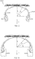
FIG. 1 is a cross-sectional view of a first embodiment of a non-pneumatic tire mounted on a wheel rim; -
FIG. 2 is a cross-sectional view of a second embodiment of a non-pneumatic tire prior to mounting on a wheel rim; -
FIG. 3 is a cross-sectional view of the non-pneumatic tire ofFIG. 2 shown mounted on a wheel rim; and -
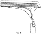
FIG. 4 is a closeup cross-sectional view of one half of a non-pneumatic tire and rim assembly of the present invention. - "Axial" and "axially" means the lines or directions that are parallel to the axis of rotation of the tire.
- "Bead" or "Bead Core" means generally that part of the tire associated with holding the tire to the rim.
- "Circumferential" means lines or directions extending along the perimeter of the surface of the annular tread perpendicular to the axial direction.
- "Cord" means one of the reinforcement strands, including fibers, which are used to reinforce the plies.
- "Inextensible" means a cord having a relative elongation at break of less than 0.2% at 10% of the breaking load, when measured from a cord extracted from a cured tire.
- "Equatorial Plane" means a plane perpendicular to the axis of rotation of the tire passing through the centerline of the tire.
- "Ply" means a layer of elastomer comprising radially deployed or otherwise parallel cords.
- "Radial" and "radially" mean directions radially toward or away from the axis of rotation of the tire.
- "Sidewall" means a portion of a tire between the tread and the bead.
- As shown in
FIGS. 1-4 , anon-pneumatic tire 100 in accordance with an embodiment of the present invention includes a radially outerground engaging tread 200, which may be a conventional tread as desired, and may include elements such as ribs, blocks, lugs, grooves, and sipes as desired to improve the performance of the tire in various conditions. - The
non-pneumatic tire 100 further comprises ashear band 300. Theshear band 300 preferably comprised of at least twoinextensible reinforcement layers shear matrix 315 of elastomer. - Each
reinforcement layer elastomer layer 310, the reinforcement cords are preferably oriented at an angle in the range of from 0 to +/- 50 degrees relative to the tire equatorial plane, and more preferably in the range of from 0 to +/-10 degrees. In the second reinforcedelastomer layer 320, the reinforcement cords are oriented preferably at an angle in the range of 0 to +/- 50 degrees relative to the tire equatorial plane, more preferably 0 to +/- 10 degrees. Preferably, the angle of reinforcement cords of the first layer is in the opposite direction of the angle of the reinforcement cords in the second layer. - As shown, the
shear band 300 may further optionally include one or moreadditional reinforcement layers - It is preferred that the radially
outermost reinforcement layers lateral ends inner reinforcement layers - The
shear matrix layer 315 located between the first andsecond reinforcement layer - The radial thickness of the
rubber layer 315 is preferably in the range of from 2.54 mm to 5.08 mm, more preferably 3.8 mm or 3.5 to 4 mm. Ifadditional reinforcement layers shear layer 315. - The belt package together with the shear layer form the
shear band 300. Theshear band 300 together with thetread 200 form an outer annular tread band. - As shown in
FIG. 1 , thenon-pneumatic tire 100 in accordance with the present invention includes two axially spaced apartsidewall portions 400 that extend inward from thetread 200 to a rim. The central portion of the tread band is in the range of from 80-90% of the total axial width of the tread band, while the lateral ends or axially outer ends are the remaining balance. - The axially outer ends of the tread band are preferably uncoupled from the carcass.
- The radially
innermost end 410 of eachsidewall portion 400 preferably includes anannular bead 420 having a bead core which is secured to the rim. Thenon-pneumatic tire 100 further includes a first layer ofply 500 which extends from thefirst bead 420 to the second bead 422. Preferably, theply 500 comprises a reinforced rubber or ply layer formed of parallel reinforcement cords that are nylon, polyester, aramid or formed of a merged cord of nylon, polyester of aramid. Preferably, the reinforcements are oriented in the radial direction. - Preferably, the layer of ply extends radially inward from the
tread 200 and is then wrapped around thefirst bead 420 and has afirst end 510 that preferably terminates underneath theshear band 300 forming an envelope ply. Thesecond end 520 of the ply likewise extends down from thetread 200, is wrapped around theopposite bead 420, and then terminates preferably underneath the shear band forming an envelope ply. - Thus, each
sidewall portion 400 preferably has two effective layers of ply. Alternatively, the first and second ends 510, 520 may wrap around thebead 420 and terminate radially outward of atip 432 of an apex 430. - Each apex 430 is preferably triangular in shape, and has a radial height as measured from the first or radially innermost end 431 of the apex 430 to the
tip 432 or radially outermost end of the apex 430. - The radial position of the
outer tip 432 is preferably in the range of from 25 percent to 75 percent of the sidewall radial height, and more preferably in the range of from 33 percent to 67 percent of the sidewall radial height. - Each lower sidewall region which is defined as the lower half of the sidewall, is preferably stiffer relative to the stiffness of the upper half of the sidewall.
- The lower sidewall may be increased in stiffness by a relatively stiff apex, or additional stiff material in the lower sidewall region such as a chafer or rim flange protector.
- The additional stiff material may be located on the axially outer portion of the lower sidewall, such as a rim flange protector or a chafer, or an axially inner portion such as a secondary apex.
- The stiffness, which is the resistance to bending, is characterized by the dynamic modulus G', which are sometimes referred to as the "shear storage modulus" or "dynamic modulus". Reference is made to Science and Technology of Rubber, second edition, 1994, Academic Press, San Diego, Calif., edited by James E. Mark et al, pages 249-254. The shear storage modulus (G') values are indicative of rubber compound stiffness which can relate to tire performance. The tan delta value at 100°C is considered as being indicative of hysteresis, or heat loss.
- In a first embodiment, the
first apex 430 comprises a relatively stiff rubber composition having a shear storage modulus G' measured at 1% strain and 100°C according to ASTM D5289 ranging from 14 to 43 MPa. In a more preferred embodiment, thefirst apex 430 comprises a rubber composition having a shear storage modulus G' measured at 1% strain and 100°C according to ASTM D5289 ranging from 23 to 43 MPa. - The stiffened lower sidewall ensures that the
ply 500 is in tension after being mounted on the rim, and also during use. - When the
ply 500 andsidewall portion 400 of thetire 100 is in the relaxed state, the ply line is curved so that thebead areas 420 are located axially inward of the shoulders or the axially outermost points of the tread band. - When the beads are loaded onto the rim, the curve is straightened and the bead or lower sidewall of the
tire 100 is moved axially outwards while still preferably remaining within the axial width of the tire shoulders or the tread band, so that theply 500 acts as a spring. - In a preferred embodiment, the lower sidewall portion comprises a
stiffener element 450 located axially outward of the apex 430. Thestiffener element 450 is preferably formed of a relatively stiff material having a shear storage modulus G' measured at 1% strain and 100°C according to ASTM D5289 ranging from 14 to 43 MPa. -
FIG. 2 illustrates a second embodiment of anon-pneumatic tire 2000 in accordance with the present invention for mounting on a rim. By design, the molded ply length is longer than the minimum distance between the molded beads and the shear band. In this embodiment, this is accomplished by making an increased radius R2 at a top 2450 of asecond apex 2300. In this design, the radius under the tread R1 is much greater than the radius R2 at the top 2450 of thesecond apex 2300. This design provides a mechanism for the cords to remain in tension as the shear band deforms into and out of the footprint. The second apex 2300 acts as a spring and provides the stiffness to tension the sidewalls. The shear band is loaded in so that it is compressed circumferentially. This combination of ply geometry will evenly load the shear band across its width, through a size dependent range of rim widths and vertical deflections. In a preferred embodiment, the first and/or second apex each comprise a stiff rubber composition having a shear storage modulus G' measured at 1% strain and 100°C according to ASTM D5289 ranging from 14 to 43 MPa, and more preferably ranging from 23 to 43 MPa. -
FIG. 3 illustrates thetire 2000 mounted on thewheel rim 1000 with the ply tensioned in the sidewalls. The beads are seated into L-shaped recesses as shown. In order to pretension the ply, thebead holders 1000 of the rim surface are displaced axially outward until the desired pretension is reached. The tension of the ply cords ensures that the tire is 100% of a top loader. This is different from a run-flat tire, wherein the stiffened sidewall members carry the load, i.e., the run-flat tire functions as a bottom loader. - As shown in
FIG. 3 , the shearband layers remain horizontal after the tire sidewalls are pretensioned, because the geometry of the ply line is designed to distribute the compressive shear band loading evenly across the full width of the shear band. The deformed shape of the ply line is between the molded shape and a fully engaged shape. A fully engaged shape is defined as R1 and R3 being minimized to 0 (approaching linear discontinuity), and with R2 approaching infinity (Linear)FIG 2 . Maximum rim axial position will remain at or below this fully engaged ply geometry. - The stiffness of each sidewall, and more preferably, the lower half of the sidewall contributes to the top loading of the
non-pneumatic tire 2000. The lower half of each sidewall is preferably relatively stiff, and may be stiffened due to a stiff apex, and/or a stiff mass of material located on the axially outer portion such as a chafer or rim flange protector. The sidewalls of the tire were pretensioned by axially expanding the wheel rim. In a preferred embodiment, a chafer or rim flange protector located axially outward of the apex comprises a relatively stiff rubber composition having a shear storage modulus G' measured at 1% strain and 100°C according to ASTM D5289 ranging from 14 to 43 MPa, and more preferably from 23 to 43 MPa. -
FIG. 4 illustrates an alternate embodiment showing an alternative ply line that has less curvature. The alternate embodiment may also have alternating molded holes in 3 dimensions for reducing weight. This would give the appearance of spokes.
Claims (15)
- A non-pneumatic tire and rim assembly comprising:a rim having a first and second bead ring holder (1000); anda non-pneumatic tire (100, 2000) having a shear band (300) and tread (200) forming a tread band, and a first and second sidewall region (400);wherein the first and second sidewall regions (400) each extend from the tread band and terminate into a first and second respective bead area (420);wherein a carcass ply (500) extends under a crown portion of the non-pneumatic tire (100), into the first and second sidewall regions (400) and to the first and second bead area (420);wherein the first and second bead area (420) are each mounted on the first and second bead ring holder (1000); andwherein the carcass ply (500) is tensioned when each bead area (420) is mounted on the respective bead ring holder (1000) of the rim.
- The non-pneumatic tire and rim assembly of claim 1 wherein the first and second sidewall (400) each have an upper sidewall region that is not connected to a lateral outermost end of the tread band.
- The non-pneumatic tire and rim assembly of claim 1 or 2 wherein each bead area (420) is tensioned outward yet located axially inward of a respective lateral outermost end of the tread band when the non-pneumatic tire (100) is mounted on the rim.
- The non-pneumatic tire and rim assembly of at least one of the previous claims wherein, when the non-pneumatic tire (100) is not mounted on the rim and is in the unloaded condition, the carcass ply (500) has a first radius (R1) under a crown portion of the non-pneumatic tire (100) and a second radius (R2) in an upper sidewall region at location where the respective sidewall region (400) and the shear band (300) are uncoupled, and wherein the first radius (R1) is greater than the second radius (R2).
- The non-pneumatic tire and rim assembly of at least one of the previous claims wherein the shear band (300) is loaded in compression when the non-pneumatic tire (100) is mounted on the rim.
- The non-pneumatic tire and rim assembly of at least one of the previous claims wherein the shear band (300) is compressed circumferentially when the non-pneumatic tire (100) is mounted on the rim.
- The non-pneumatic tire and rim assembly of at least one of the previous claims wherein the axial distance between the first and second bead rings (1000) is axially adjustable.
- The non-pneumatic tire and rim assembly of at least one of the previous claims wherein each sidewall region (400) has at least two layers of ply.
- The non-pneumatic tire and rim assembly of at least one of the previous claims wherein the first end and the second end of the carcass ply (500) are located in the crown portion of the non-pneumatic tire (100) and/or wherein the carcass ply (500) extends around each respective bead core in the bead area (420) of the non-pneumatic tire (100).
- The non-pneumatic tire and rim assembly of at least one of the previous claims wherein the sidewalls regions (400) are angled at an angle in a range of from 70 to 85 degrees with respect to a horizontal line connecting the radially outermost points of the first and second bead ring holder (1000).
- The non-pneumatic tire and rim assembly of at least one of the previous claims wherein each bead area further includes an apex (430, 2300).
- The non-pneumatic tire and rim assembly of claim 11 wherein the apex (430, 2300) is formed of a relatively stiff material having a shear storage modulus G' measured at 1% strain and 100°C according to ASTM D5289 ranging from 14 to 43 MPa.
- The non-pneumatic tire and rim assembly of at least one of the previous claims wherein each bead area (420) further includes a second apex (2300), wherein the second apex (2300) is formed of a relatively stiff material having a shear storage modulus G' measured at 1% strain and 100°C according to ASTM D5289 ranging from 14 to 43 MPa.
- The non-pneumatic tire and rim assembly of at least one of the previous claims wherein a lower sidewall portion comprises a stiffener element (450) located axially outward of the apex (430), and wherein the stiffener element (450) is formed of a relatively stiff material having a shear storage modulus G' measured at 1% strain and 100°C according to ASTM D5289 ranging from 14 to 43 MPa.
- The non-pneumatic tire and rim assembly of at least one of the previous claims wherein a lower sidewall portion has a chafer, and wherein the chafer is formed of a relatively stiff material having a shear storage modulus G' measured at 1% strain and 100°C according to ASTM D5289 ranging from 14 to 43 MPa.
Applications Claiming Priority (2)
| Application Number | Priority Date | Filing Date | Title |
|---|---|---|---|
| US202063126201P | 2020-12-16 | 2020-12-16 | |
| US17/452,662 US20220185016A1 (en) | 2020-12-16 | 2021-10-28 | Non-pneumatic tire |
Publications (2)
| Publication Number | Publication Date |
|---|---|
| EP4015242A1 true EP4015242A1 (en) | 2022-06-22 |
| EP4015242B1 EP4015242B1 (en) | 2024-01-31 |
Family
ID=78822157
Family Applications (1)
| Application Number | Title | Priority Date | Filing Date |
|---|---|---|---|
| EP21212358.2A Active EP4015242B1 (en) | 2020-12-16 | 2021-12-03 | Non-pneumatic tire and rim assembly |
Country Status (6)
| Country | Link |
|---|---|
| US (1) | US20220185016A1 (en) |
| EP (1) | EP4015242B1 (en) |
| JP (1) | JP2022095590A (en) |
| KR (1) | KR102662136B1 (en) |
| CN (1) | CN114633586B (en) |
| BR (1) | BR102021024572A2 (en) |
Families Citing this family (2)
| Publication number | Priority date | Publication date | Assignee | Title |
|---|---|---|---|---|
| EP4361170A1 (en) | 2021-06-24 | 2024-05-01 | Yoshihiro Watanabe | Antibody-inducing polypeptide and vaccine |
| US20250042205A1 (en) * | 2023-07-31 | 2025-02-06 | The Goodyear Tire & Rubber Company | Non-pneumatic tire |
Citations (7)
| Publication number | Priority date | Publication date | Assignee | Title |
|---|---|---|---|---|
| US2650633A (en) * | 1949-01-26 | 1953-09-01 | Us Rubber Co | Resilient tire |
| US4241775A (en) * | 1977-08-25 | 1980-12-30 | Dunlop Limited | Tires |
| US4580610A (en) * | 1981-10-09 | 1986-04-08 | Dunlop Limited | Tire |
| EP1381527A1 (en) * | 2001-04-16 | 2004-01-21 | Société de Technologie Michelin | Structurally supported resilient tire with bias ply carcass |
| FR2844480A1 (en) * | 2002-09-12 | 2004-03-19 | Jean Gergele | Vehicle wheel with non-pneumatic tire has tire made with side walls containing reinforcing cables or cords separated by low-friction material |
| US20060249236A1 (en) * | 2005-05-06 | 2006-11-09 | Michael Moon | Non-pneumatic vehicle tire |
| US20190344616A1 (en) * | 2016-09-27 | 2019-11-14 | Bridgestone Americas Tire Operations, Llc | Wheel with bead locks |
Family Cites Families (17)
| Publication number | Priority date | Publication date | Assignee | Title |
|---|---|---|---|---|
| US3238988A (en) * | 1965-02-23 | 1966-03-08 | V Alfredo Roque | Tire |
| CA1126635A (en) * | 1979-06-06 | 1982-06-29 | Mark H. Mineur | Pneumatic safety tire |
| DE19709160A1 (en) * | 1997-03-06 | 1998-09-17 | Continental Ag | Vehicle radial tyre |
| US6167931B1 (en) * | 1999-03-22 | 2001-01-02 | Kings Glory Co., Ltd. | Inflation-free tire structure |
| US6695025B1 (en) * | 1999-05-18 | 2004-02-24 | The Goodyear Tire & Rubber Company | Runflat tire construction with ply cords having a variable modulus of elasticity |
| PL356125A1 (en) * | 1999-12-10 | 2004-06-14 | Michelin Recherche Et Technique S.A. | Structurally supported resilient tire |
| US6983776B2 (en) * | 1999-12-10 | 2006-01-10 | Michelin Recherche Et Technique S.A. | Structurally supported resilient tire with bias ply carcass |
| US6994134B2 (en) * | 2001-10-05 | 2006-02-07 | Michelin Recherche Et Technique S.A. | Structurally supported resilient tire and materials |
| US20030111152A1 (en) * | 2001-12-06 | 2003-06-19 | Laurent Colantonio | Pneumatic tire bead area construction for improved chafer cracking resistance during run-flat operation |
| JP2006130942A (en) * | 2004-11-02 | 2006-05-25 | Bridgestone Corp | Pneumatic radial tire |
| FR2925393B1 (en) * | 2007-12-21 | 2009-12-18 | Michelin Soc Tech | PNEUMATIC TIRE FOR FLAT ROLL WITH ADDITIONAL FLANK REINFORCEMENT. |
| US20110174422A1 (en) * | 2010-01-20 | 2011-07-21 | Kelly Sue King | Pneumatic tire with compound apex |
| CN106163832A (en) * | 2014-04-07 | 2016-11-23 | 普利司通美国轮胎运营有限责任公司 | Tires with prestressed annular elements |
| US20170174002A1 (en) * | 2015-12-21 | 2017-06-22 | The Goodyear Tire & Rubber Company | Non-pneumatic tire with geodesic connecting web |
| EP3184327A1 (en) * | 2015-12-22 | 2017-06-28 | The Goodyear Tire & Rubber Company | Non-pneumatic tire |
| US20190299717A1 (en) * | 2018-03-28 | 2019-10-03 | The Goodyear Tire & Rubber Company | Wheel and tire assembly |
| US20200198411A1 (en) * | 2018-12-20 | 2020-06-25 | The Goodyear Tire & Rubber Company | Tire with no ply turnup |
-
2021
- 2021-10-28 US US17/452,662 patent/US20220185016A1/en not_active Abandoned
- 2021-12-03 BR BR102021024572-7A patent/BR102021024572A2/en not_active Application Discontinuation
- 2021-12-03 EP EP21212358.2A patent/EP4015242B1/en active Active
- 2021-12-09 CN CN202111499358.XA patent/CN114633586B/en active Active
- 2021-12-14 KR KR1020210178997A patent/KR102662136B1/en active Active
- 2021-12-15 JP JP2021203584A patent/JP2022095590A/en active Pending
Patent Citations (7)
| Publication number | Priority date | Publication date | Assignee | Title |
|---|---|---|---|---|
| US2650633A (en) * | 1949-01-26 | 1953-09-01 | Us Rubber Co | Resilient tire |
| US4241775A (en) * | 1977-08-25 | 1980-12-30 | Dunlop Limited | Tires |
| US4580610A (en) * | 1981-10-09 | 1986-04-08 | Dunlop Limited | Tire |
| EP1381527A1 (en) * | 2001-04-16 | 2004-01-21 | Société de Technologie Michelin | Structurally supported resilient tire with bias ply carcass |
| FR2844480A1 (en) * | 2002-09-12 | 2004-03-19 | Jean Gergele | Vehicle wheel with non-pneumatic tire has tire made with side walls containing reinforcing cables or cords separated by low-friction material |
| US20060249236A1 (en) * | 2005-05-06 | 2006-11-09 | Michael Moon | Non-pneumatic vehicle tire |
| US20190344616A1 (en) * | 2016-09-27 | 2019-11-14 | Bridgestone Americas Tire Operations, Llc | Wheel with bead locks |
Non-Patent Citations (1)
| Title |
|---|
| "Science and Technology of Rubber", 1994, ACADEMIC PRESS, pages: 249 - 254 |
Also Published As
| Publication number | Publication date |
|---|---|
| KR20220086504A (en) | 2022-06-23 |
| US20220185016A1 (en) | 2022-06-16 |
| BR102021024572A2 (en) | 2022-06-28 |
| CN114633586B (en) | 2024-12-13 |
| KR102662136B1 (en) | 2024-04-29 |
| EP4015242B1 (en) | 2024-01-31 |
| JP2022095590A (en) | 2022-06-28 |
| CN114633586A (en) | 2022-06-17 |
Similar Documents
| Publication | Publication Date | Title |
|---|---|---|
| JPH04230408A (en) | Tire for automobile | |
| US7926533B2 (en) | Pneumatic tire with increased lower sidewall durability | |
| CN109414966B (en) | Tire with reduced weight bead area | |
| US20090294007A1 (en) | Performance tire with sidewall insert | |
| US9073389B2 (en) | All steel fabric radial construction for agricultural tires | |
| EP4015242B1 (en) | Non-pneumatic tire and rim assembly | |
| CN1328070C (en) | Vehicle tire with self-supporting function and rim for the tire | |
| US6792986B2 (en) | Underlay structure for increased crown stiffening | |
| EP1388436B1 (en) | Ruflat tire having sidewall thickness for optimized ride comfort | |
| JPH01156107A (en) | Pneumatic tire | |
| US6422280B1 (en) | Heavy duty tire with specified bead design | |
| EP0958153B1 (en) | Heavy duty tire with specified bead design | |
| EP1097048B1 (en) | Tread reinforcement means for extended mobility tire | |
| US6561245B1 (en) | Thread reinforcement means for extended mobility tire | |
| JP4394292B2 (en) | Reinforced wedge insert structure for tires with enhanced mobility | |
| KR102646626B1 (en) | Non-pneumatic tire | |
| CN112739557B (en) | Tire with reduced weight bead area | |
| JP4149672B2 (en) | Improved sidewall with insert structure for run-flat tires | |
| US7249622B2 (en) | Tire with deep tread grooves | |
| EP4039505A2 (en) | Non-pneumatic tire assembly | |
| CN101213095B (en) | tires for heavy vehicles | |
| US20160167451A1 (en) | Rim/tire interface structure |
Legal Events
| Date | Code | Title | Description |
|---|---|---|---|
| PUAI | Public reference made under article 153(3) epc to a published international application that has entered the european phase |
Free format text: ORIGINAL CODE: 0009012 |
|
| STAA | Information on the status of an ep patent application or granted ep patent |
Free format text: STATUS: THE APPLICATION HAS BEEN PUBLISHED |
|
| AK | Designated contracting states |
Kind code of ref document: A1 Designated state(s): AL AT BE BG CH CY CZ DE DK EE ES FI FR GB GR HR HU IE IS IT LI LT LU LV MC MK MT NL NO PL PT RO RS SE SI SK SM TR |
|
| STAA | Information on the status of an ep patent application or granted ep patent |
Free format text: STATUS: REQUEST FOR EXAMINATION WAS MADE |
|
| 17P | Request for examination filed |
Effective date: 20221222 |
|
| RBV | Designated contracting states (corrected) |
Designated state(s): AL AT BE BG CH CY CZ DE DK EE ES FI FR GB GR HR HU IE IS IT LI LT LU LV MC MK MT NL NO PL PT RO RS SE SI SK SM TR |
|
| GRAP | Despatch of communication of intention to grant a patent |
Free format text: ORIGINAL CODE: EPIDOSNIGR1 |
|
| STAA | Information on the status of an ep patent application or granted ep patent |
Free format text: STATUS: GRANT OF PATENT IS INTENDED |
|
| INTG | Intention to grant announced |
Effective date: 20230822 |
|
| GRAS | Grant fee paid |
Free format text: ORIGINAL CODE: EPIDOSNIGR3 |
|
| GRAA | (expected) grant |
Free format text: ORIGINAL CODE: 0009210 |
|
| STAA | Information on the status of an ep patent application or granted ep patent |
Free format text: STATUS: THE PATENT HAS BEEN GRANTED |
|
| AK | Designated contracting states |
Kind code of ref document: B1 Designated state(s): AL AT BE BG CH CY CZ DE DK EE ES FI FR GB GR HR HU IE IS IT LI LT LU LV MC MK MT NL NO PL PT RO RS SE SI SK SM TR |
|
| REG | Reference to a national code |
Ref country code: GB Ref legal event code: FG4D Ref country code: CH Ref legal event code: EP |
|
| REG | Reference to a national code |
Ref country code: DE Ref legal event code: R096 Ref document number: 602021008948 Country of ref document: DE |
|
| REG | Reference to a national code |
Ref country code: IE Ref legal event code: FG4D |
|
| REG | Reference to a national code |
Ref country code: LT Ref legal event code: MG9D |
|
| REG | Reference to a national code |
Ref country code: NL Ref legal event code: MP Effective date: 20240131 |
|
| PG25 | Lapsed in a contracting state [announced via postgrant information from national office to epo] |
Ref country code: IS Free format text: LAPSE BECAUSE OF FAILURE TO SUBMIT A TRANSLATION OF THE DESCRIPTION OR TO PAY THE FEE WITHIN THE PRESCRIBED TIME-LIMIT Effective date: 20240531 |
|
| PG25 | Lapsed in a contracting state [announced via postgrant information from national office to epo] |
Ref country code: LT Free format text: LAPSE BECAUSE OF FAILURE TO SUBMIT A TRANSLATION OF THE DESCRIPTION OR TO PAY THE FEE WITHIN THE PRESCRIBED TIME-LIMIT Effective date: 20240131 |
|
| PG25 | Lapsed in a contracting state [announced via postgrant information from national office to epo] |
Ref country code: GR Free format text: LAPSE BECAUSE OF FAILURE TO SUBMIT A TRANSLATION OF THE DESCRIPTION OR TO PAY THE FEE WITHIN THE PRESCRIBED TIME-LIMIT Effective date: 20240501 |
|
| REG | Reference to a national code |
Ref country code: AT Ref legal event code: MK05 Ref document number: 1653625 Country of ref document: AT Kind code of ref document: T Effective date: 20240131 |
|
| PG25 | Lapsed in a contracting state [announced via postgrant information from national office to epo] |
Ref country code: HR Free format text: LAPSE BECAUSE OF FAILURE TO SUBMIT A TRANSLATION OF THE DESCRIPTION OR TO PAY THE FEE WITHIN THE PRESCRIBED TIME-LIMIT Effective date: 20240131 Ref country code: NL Free format text: LAPSE BECAUSE OF FAILURE TO SUBMIT A TRANSLATION OF THE DESCRIPTION OR TO PAY THE FEE WITHIN THE PRESCRIBED TIME-LIMIT Effective date: 20240131 Ref country code: RS Free format text: LAPSE BECAUSE OF FAILURE TO SUBMIT A TRANSLATION OF THE DESCRIPTION OR TO PAY THE FEE WITHIN THE PRESCRIBED TIME-LIMIT Effective date: 20240430 |
|
| PG25 | Lapsed in a contracting state [announced via postgrant information from national office to epo] |
Ref country code: ES Free format text: LAPSE BECAUSE OF FAILURE TO SUBMIT A TRANSLATION OF THE DESCRIPTION OR TO PAY THE FEE WITHIN THE PRESCRIBED TIME-LIMIT Effective date: 20240131 |
|
| PG25 | Lapsed in a contracting state [announced via postgrant information from national office to epo] |
Ref country code: AT Free format text: LAPSE BECAUSE OF FAILURE TO SUBMIT A TRANSLATION OF THE DESCRIPTION OR TO PAY THE FEE WITHIN THE PRESCRIBED TIME-LIMIT Effective date: 20240131 |
|
| PG25 | Lapsed in a contracting state [announced via postgrant information from national office to epo] |
Ref country code: RS Free format text: LAPSE BECAUSE OF FAILURE TO SUBMIT A TRANSLATION OF THE DESCRIPTION OR TO PAY THE FEE WITHIN THE PRESCRIBED TIME-LIMIT Effective date: 20240430 Ref country code: NO Free format text: LAPSE BECAUSE OF FAILURE TO SUBMIT A TRANSLATION OF THE DESCRIPTION OR TO PAY THE FEE WITHIN THE PRESCRIBED TIME-LIMIT Effective date: 20240430 Ref country code: NL Free format text: LAPSE BECAUSE OF FAILURE TO SUBMIT A TRANSLATION OF THE DESCRIPTION OR TO PAY THE FEE WITHIN THE PRESCRIBED TIME-LIMIT Effective date: 20240131 Ref country code: LT Free format text: LAPSE BECAUSE OF FAILURE TO SUBMIT A TRANSLATION OF THE DESCRIPTION OR TO PAY THE FEE WITHIN THE PRESCRIBED TIME-LIMIT Effective date: 20240131 Ref country code: IS Free format text: LAPSE BECAUSE OF FAILURE TO SUBMIT A TRANSLATION OF THE DESCRIPTION OR TO PAY THE FEE WITHIN THE PRESCRIBED TIME-LIMIT Effective date: 20240531 Ref country code: HR Free format text: LAPSE BECAUSE OF FAILURE TO SUBMIT A TRANSLATION OF THE DESCRIPTION OR TO PAY THE FEE WITHIN THE PRESCRIBED TIME-LIMIT Effective date: 20240131 Ref country code: GR Free format text: LAPSE BECAUSE OF FAILURE TO SUBMIT A TRANSLATION OF THE DESCRIPTION OR TO PAY THE FEE WITHIN THE PRESCRIBED TIME-LIMIT Effective date: 20240501 Ref country code: FI Free format text: LAPSE BECAUSE OF FAILURE TO SUBMIT A TRANSLATION OF THE DESCRIPTION OR TO PAY THE FEE WITHIN THE PRESCRIBED TIME-LIMIT Effective date: 20240131 Ref country code: ES Free format text: LAPSE BECAUSE OF FAILURE TO SUBMIT A TRANSLATION OF THE DESCRIPTION OR TO PAY THE FEE WITHIN THE PRESCRIBED TIME-LIMIT Effective date: 20240131 Ref country code: BG Free format text: LAPSE BECAUSE OF FAILURE TO SUBMIT A TRANSLATION OF THE DESCRIPTION OR TO PAY THE FEE WITHIN THE PRESCRIBED TIME-LIMIT Effective date: 20240131 Ref country code: AT Free format text: LAPSE BECAUSE OF FAILURE TO SUBMIT A TRANSLATION OF THE DESCRIPTION OR TO PAY THE FEE WITHIN THE PRESCRIBED TIME-LIMIT Effective date: 20240131 |
|
| PG25 | Lapsed in a contracting state [announced via postgrant information from national office to epo] |
Ref country code: PL Free format text: LAPSE BECAUSE OF FAILURE TO SUBMIT A TRANSLATION OF THE DESCRIPTION OR TO PAY THE FEE WITHIN THE PRESCRIBED TIME-LIMIT Effective date: 20240131 Ref country code: PT Free format text: LAPSE BECAUSE OF FAILURE TO SUBMIT A TRANSLATION OF THE DESCRIPTION OR TO PAY THE FEE WITHIN THE PRESCRIBED TIME-LIMIT Effective date: 20240531 |
|
| PG25 | Lapsed in a contracting state [announced via postgrant information from national office to epo] |
Ref country code: SE Free format text: LAPSE BECAUSE OF FAILURE TO SUBMIT A TRANSLATION OF THE DESCRIPTION OR TO PAY THE FEE WITHIN THE PRESCRIBED TIME-LIMIT Effective date: 20240131 Ref country code: PT Free format text: LAPSE BECAUSE OF FAILURE TO SUBMIT A TRANSLATION OF THE DESCRIPTION OR TO PAY THE FEE WITHIN THE PRESCRIBED TIME-LIMIT Effective date: 20240531 Ref country code: PL Free format text: LAPSE BECAUSE OF FAILURE TO SUBMIT A TRANSLATION OF THE DESCRIPTION OR TO PAY THE FEE WITHIN THE PRESCRIBED TIME-LIMIT Effective date: 20240131 Ref country code: LV Free format text: LAPSE BECAUSE OF FAILURE TO SUBMIT A TRANSLATION OF THE DESCRIPTION OR TO PAY THE FEE WITHIN THE PRESCRIBED TIME-LIMIT Effective date: 20240131 |
|
| PG25 | Lapsed in a contracting state [announced via postgrant information from national office to epo] |
Ref country code: DK Free format text: LAPSE BECAUSE OF FAILURE TO SUBMIT A TRANSLATION OF THE DESCRIPTION OR TO PAY THE FEE WITHIN THE PRESCRIBED TIME-LIMIT Effective date: 20240131 |
|
| PG25 | Lapsed in a contracting state [announced via postgrant information from national office to epo] |
Ref country code: SM Free format text: LAPSE BECAUSE OF FAILURE TO SUBMIT A TRANSLATION OF THE DESCRIPTION OR TO PAY THE FEE WITHIN THE PRESCRIBED TIME-LIMIT Effective date: 20240131 |
|
| PG25 | Lapsed in a contracting state [announced via postgrant information from national office to epo] |
Ref country code: CZ Free format text: LAPSE BECAUSE OF FAILURE TO SUBMIT A TRANSLATION OF THE DESCRIPTION OR TO PAY THE FEE WITHIN THE PRESCRIBED TIME-LIMIT Effective date: 20240131 Ref country code: EE Free format text: LAPSE BECAUSE OF FAILURE TO SUBMIT A TRANSLATION OF THE DESCRIPTION OR TO PAY THE FEE WITHIN THE PRESCRIBED TIME-LIMIT Effective date: 20240131 |
|
| PG25 | Lapsed in a contracting state [announced via postgrant information from national office to epo] |
Ref country code: SK Free format text: LAPSE BECAUSE OF FAILURE TO SUBMIT A TRANSLATION OF THE DESCRIPTION OR TO PAY THE FEE WITHIN THE PRESCRIBED TIME-LIMIT Effective date: 20240131 |
|
| PG25 | Lapsed in a contracting state [announced via postgrant information from national office to epo] |
Ref country code: SM Free format text: LAPSE BECAUSE OF FAILURE TO SUBMIT A TRANSLATION OF THE DESCRIPTION OR TO PAY THE FEE WITHIN THE PRESCRIBED TIME-LIMIT Effective date: 20240131 Ref country code: SK Free format text: LAPSE BECAUSE OF FAILURE TO SUBMIT A TRANSLATION OF THE DESCRIPTION OR TO PAY THE FEE WITHIN THE PRESCRIBED TIME-LIMIT Effective date: 20240131 Ref country code: RO Free format text: LAPSE BECAUSE OF FAILURE TO SUBMIT A TRANSLATION OF THE DESCRIPTION OR TO PAY THE FEE WITHIN THE PRESCRIBED TIME-LIMIT Effective date: 20240131 Ref country code: EE Free format text: LAPSE BECAUSE OF FAILURE TO SUBMIT A TRANSLATION OF THE DESCRIPTION OR TO PAY THE FEE WITHIN THE PRESCRIBED TIME-LIMIT Effective date: 20240131 Ref country code: DK Free format text: LAPSE BECAUSE OF FAILURE TO SUBMIT A TRANSLATION OF THE DESCRIPTION OR TO PAY THE FEE WITHIN THE PRESCRIBED TIME-LIMIT Effective date: 20240131 Ref country code: CZ Free format text: LAPSE BECAUSE OF FAILURE TO SUBMIT A TRANSLATION OF THE DESCRIPTION OR TO PAY THE FEE WITHIN THE PRESCRIBED TIME-LIMIT Effective date: 20240131 |
|
| REG | Reference to a national code |
Ref country code: DE Ref legal event code: R097 Ref document number: 602021008948 Country of ref document: DE |
|
| PLBE | No opposition filed within time limit |
Free format text: ORIGINAL CODE: 0009261 |
|
| STAA | Information on the status of an ep patent application or granted ep patent |
Free format text: STATUS: NO OPPOSITION FILED WITHIN TIME LIMIT |
|
| 26N | No opposition filed |
Effective date: 20241101 |
|
| PG25 | Lapsed in a contracting state [announced via postgrant information from national office to epo] |
Ref country code: SI Free format text: LAPSE BECAUSE OF FAILURE TO SUBMIT A TRANSLATION OF THE DESCRIPTION OR TO PAY THE FEE WITHIN THE PRESCRIBED TIME-LIMIT Effective date: 20240131 |
|
| PGFP | Annual fee paid to national office [announced via postgrant information from national office to epo] |
Ref country code: IT Payment date: 20241231 Year of fee payment: 4 |
|
| REG | Reference to a national code |
Ref country code: DE Ref legal event code: R119 Ref document number: 602021008948 Country of ref document: DE |
|
| PG25 | Lapsed in a contracting state [announced via postgrant information from national office to epo] |
Ref country code: MC Free format text: LAPSE BECAUSE OF FAILURE TO SUBMIT A TRANSLATION OF THE DESCRIPTION OR TO PAY THE FEE WITHIN THE PRESCRIBED TIME-LIMIT Effective date: 20240131 |
|
| REG | Reference to a national code |
Ref country code: CH Ref legal event code: PL |
|
| PG25 | Lapsed in a contracting state [announced via postgrant information from national office to epo] |
Ref country code: LU Free format text: LAPSE BECAUSE OF NON-PAYMENT OF DUE FEES Effective date: 20241203 |
|
| REG | Reference to a national code |
Ref country code: BE Ref legal event code: MM Effective date: 20241231 |
|
| PG25 | Lapsed in a contracting state [announced via postgrant information from national office to epo] |
Ref country code: DE Free format text: LAPSE BECAUSE OF NON-PAYMENT OF DUE FEES Effective date: 20250701 |
|
| PG25 | Lapsed in a contracting state [announced via postgrant information from national office to epo] |
Ref country code: BE Free format text: LAPSE BECAUSE OF NON-PAYMENT OF DUE FEES Effective date: 20241231 |
|
| PG25 | Lapsed in a contracting state [announced via postgrant information from national office to epo] |
Ref country code: FR Free format text: LAPSE BECAUSE OF NON-PAYMENT OF DUE FEES Effective date: 20241231 |
|
| PG25 | Lapsed in a contracting state [announced via postgrant information from national office to epo] |
Ref country code: CH Free format text: LAPSE BECAUSE OF NON-PAYMENT OF DUE FEES Effective date: 20241231 |
|
| PG25 | Lapsed in a contracting state [announced via postgrant information from national office to epo] |
Ref country code: IE Free format text: LAPSE BECAUSE OF NON-PAYMENT OF DUE FEES Effective date: 20241203 |
|
| PG25 | Lapsed in a contracting state [announced via postgrant information from national office to epo] |
Ref country code: CY Free format text: LAPSE BECAUSE OF FAILURE TO SUBMIT A TRANSLATION OF THE DESCRIPTION OR TO PAY THE FEE WITHIN THE PRESCRIBED TIME-LIMIT; INVALID AB INITIO Effective date: 20211203 |
|
| PG25 | Lapsed in a contracting state [announced via postgrant information from national office to epo] |
Ref country code: TR Free format text: LAPSE BECAUSE OF FAILURE TO SUBMIT A TRANSLATION OF THE DESCRIPTION OR TO PAY THE FEE WITHIN THE PRESCRIBED TIME-LIMIT Effective date: 20240131 |
|
| PG25 | Lapsed in a contracting state [announced via postgrant information from national office to epo] |
Ref country code: HU Free format text: LAPSE BECAUSE OF FAILURE TO SUBMIT A TRANSLATION OF THE DESCRIPTION OR TO PAY THE FEE WITHIN THE PRESCRIBED TIME-LIMIT; INVALID AB INITIO Effective date: 20211203 |